

Page 1
ORDER NO. DSC1002001CE
Digital Camera
Model No. DMC-FP1P
DMC-FP1PC
DMC-FP1PR
DMC-FP1PU
DMC-FP1EB
DMC-FP1EE
DMC-FP1EF
B26
DMC-FP1EG
DMC-FP1EP
DMC-FP1GC
DMC-FP1GD
DMC-FP1GF
DMC-FP1GH
DMC-FP1GK
DMC-FP1GN
DMC-FP1GT
DMC-FP2P
DMC-FP2PC
DMC-FP2PR
DMC-FP2PU
DMC-FP2EB
DMC-FP2EE
© Panasonic Corporation 2010 Unauthorized copying and distribution is a violation of law.
Page 2
Vol. 1
DMC-FP2EF
DMC-FP2EG
DMC-FP2EP
Colour
[ DMC-FP1 ]
(S)...........Silver Type (except PC/EB/EF/GD)
(K)...........Black Type
(R)...........Red Type (only P/PC/GC)
(P)...........Pink Type (except PC/EE/GD)
(A)...........Blue Type (except PC/PR/GC/GD)
(D)...........Orange Type (only P/EB/EE/EF/EG/EP/GK)
(G)..........Green Type (only P/PU/GD/GK/GN)
(H)...........Gray Type (only P/PC)
[ DMC-FP2 ]
(S)...........Silver Type (only PU/EE/EG/EP)
(K)...........Black Type (except P/PC)
(R)...........Red Type (except PR)
(A)...........Blue Type (only P/PU/EB/EG)
(D)...........Orange Type (only P)
(G)..........Green Type (only P)
(H)...........Gray Type (only P/PC)
(PA).........Light Pink Type (except P/PC/EE/EP)
2
Page 3

TABLE OF CONTENTS
PAGE PAGE
1 Safety Precautions----------------------------------------------- 4
1.1. General Guidelines---------------------------------------- 4
1.2. Leakage Current Cold Check--------------------------- 4
1.3. Leakage Current Hot Check (See Figure 1.) ------- 4
1.4. How to Discharge the Capacitor on
E.Capacitor P.C.B. ---------------------------------------- 5
2 Warning-------------------------------------------------------------- 6
2.1. Prevention of Electrostatic Discharge (ESD)
to Electrostatically Sensitive (ES) Devices---------- 6
2.2. How to Recycle the Lithium Ion Battery (U.S.
Only)---------------------------------------------------------- 6
2.3. Caution for AC Cord(For EB/GC/GH) ---------------- 7
2.4. How to Replace the Lithium Battery ------------------ 8
3 Service Navigation----------------------------------------------- 9
3.1. Introduction-------------------------------------------------- 9
3.2. General Description About Lead Free Solder
(PbF)---------------------------------------------------------- 9
3.3. Important Notice 1:(Other than U.S.A. and
Canadian Market) ----------------------------------------- 9
3.4. How to Define the Model Suffix (NTSC or PAL
model)-------------------------------------------------------10
4 Specifications ----------------------------------------------------14
5 Location of Controls and Components------------------15
6 Service Mode -----------------------------------------------------17
6.1. Error Code Memory Function--------------------------17
6.2. ICS (Indication of additional Camera Settings
when picture was taken) function---------------------19
7 Service Fixture & Tools----------------------------------------21
7.1. Service Fixture and Tools-------------------------------21
7.2. When Replacing the Main P.C.B.---------------------22
7.3. Service Position-------------------------------------------22
8 Disassembly and Assembly Instructions ---------------23
8.1. Disassembly Flow Chart--------------------------------23
8.2. PCB Location----------------------------------------------23
8.3. Disassembly Procedure---------------------------------24
9 Measurements and Adjustments---------------------------31
9.1. Introduction-------------------------------------------------31
9.2. Before Disassembling the unit ------------------------31
9.3. Details of Electrical Adjustment-----------------------33
9.4. After Adjustment------------------------------------------36
10 Maintenance-------------------------------------------------------37
10.1. Cleaning Lens and LCD Panel------------------------37
3
Page 4
1 Safety Precautions
1.1. General Guidelines
1. IMPORTANT SAFETY NOTICE
There are special components used in this equipment
which are important for safety. These parts are marked by
in the Schematic Diagrams, Circuit Board Layout,
Exploded Views and Replacement Parts List. It is essential that these critical parts should be replaced with manufacturer’s specified parts to prevent X-RADIATION,
shock, fire, or other hazards. Do not modify the original
design without permission of manufacturer.
2. An Isolation Transformer should always be used during
the servicing of AC Adaptor whose chassis is not isolated
from the AC power line. Use a transformer of adequate
power rating as this protects the technician from accidents resulting in personal injury from electrical shocks. It
will also protect AC Adaptor from being damaged by accidental shorting that may occur during servicing.
3. When servicing, observe the original lead dress. If a short
circuit is found, replace all parts which have been overheated or damaged by the short circuit.
4. After servicing, see to it that all the protective devices
such as insulation barriers, insulation papers shields are
properly installed.
5. After servicing, make the following leakage current
checks to prevent the customer from being exposed to
shock hazards.
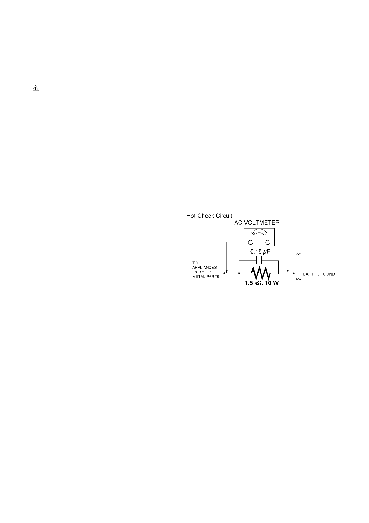
1.3. Leakage Current Hot Check
(See Figure 1.)
1. Plug the AC cord directly into the AC outlet. Do not use
an isolation transformer for this check.
2. Connect a 1.5 kΩ, 10 W resistor, in parallel with a 0.15 μF
capacitor, between each exposed metallic part on the set
and a good earth ground, as shown in Figure 1.
3. Use an AC voltmeter, with 1 kΩ/V or more sensitivity, to
measure the potential across the resistor.
4. Check each exposed metallic part, and measure the voltage at each point.
5. Reverse the AC plug in the AC outlet and repeat each of
the above measurements.
6. The potential at any point should not exceed 0.75 V RMS.
A leakage current tester (Simpson Model 229 or equivalent) may be used to make the hot checks, leakage current must not exceed 1/2 mA. In case a measurement is
outside of the limits specified, there is a possibility of a
shock hazard, and the equipment should be repaired and
rechecked before it is returned to the customer.
1.2. Leakage Current Cold Check
1. Unplug the AC cord and connect a jumper between the
two prongs on the plug.
2. Measure the resistance value, with an ohmmeter,
between the jumpered AC plug and each exposed metallic cabinet part on the equipment such as screwheads,
connectors, control shafts, etc. When the exposed metallic part has a return path to the chassis, the reading
should be between 1 MΩ and 5.2 MΩ. When the exposed
metal does not have a return path to the chassis, the
reading must be infinity.
Figure. 1
4
Page 5
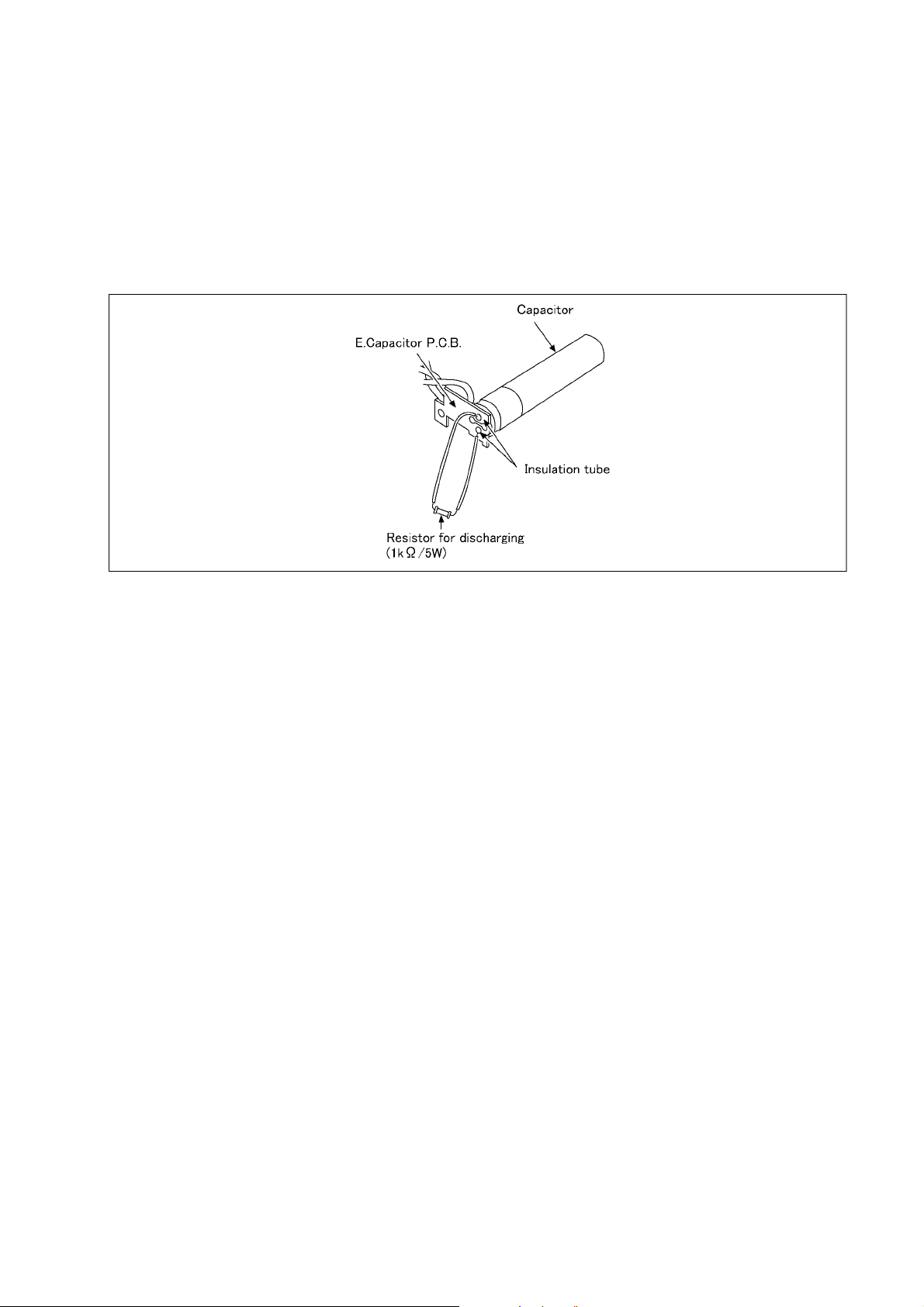
1.4. How to Discharge the Capacitor on E.Capacitor P.C.B.
CAUTION:
1. Be sure to discharge the capacitor on E.Capacitor P.C.B..
2. Be careful of the high voltage circuit on E.Capacitor P.C.B. when servicing.
[Discharging Procedure]
1. Refer to the disassemble procedure and remove the necessary parts/unit.
2. Install the insulation tube onto the lead part of resistor (ERG5SJ102:1kΩ /5W).
(an equivalent type of resistor may be used.)
3. Place a resistor between both terminals of capacitor on the E.Capacitor P.C.B. for approx. 5 seconds.
4. After discharging, confirm that the capacitor voltage is lower than 10V using a voltmeter.
Fig. F1
5
Page 6
2Warning
2.1. Prevention of Electrostatic Discharge (ESD) to Electrostatically
Sensitive (ES) Devices
Some semiconductor (solid state) devices can be damaged easily by static electricity. Such components commonly are called Electrostatically Sensitive (ES) Devices.
The following techniques should be used to help reduce the incidence of component damage caused by electrostatic discharge
(ESD).
1. Immediately before handling any semiconductor component or semiconductor-equipped assembly, drain off any ESD on your
body by touching a known earth ground. Alternatively, obtain and wear a commercially available discharging ESD wrist strap,
which should be removed for potential shock reasons prior to applying power to the unit under test.
2. After removing an electrical assembly equipped with ES devices, place the assembly on a conductive surface su ch as a luminum foil, to prevent electrostatic charge buildup or exposure of the assembly.
3. Use only a grounded-tip soldering iron to solder or unsolder ES devices.
4. Use only an antistatic solder removal device. Some solder removal devices not classified as "antistatic (ESD protected)" can
generate electrical charge sufficient to damage ES devices.
5. Do not use freon-propelled chemicals. These can generate electrical charges sufficient to damage ES devices.
6. Do not remove a replacement ES device from its protective package until immediately before you are ready to install it. (Most
replacement ES devices are packaged with leads electrically shorted together by conductive foam, aluminum foil or comparable conductive material).
7. Immediately before removing the protective material from the leads of a replacement ES device, touch the protective material
to the chassis or circuit assembly into which the device will be installed.
CAUTION :
Be sure no power is applied to the chassis or circuit, and observe all other safety precautions.
8. Minimize bodily motions when handling unpackaged replacement ES devices. (Otherwise harmless motion such as the
brushing together of your clothes fabric or the lifting of your foot from a carpeted floor can generate static electricity (ESD) sufficient to damage an ES device).
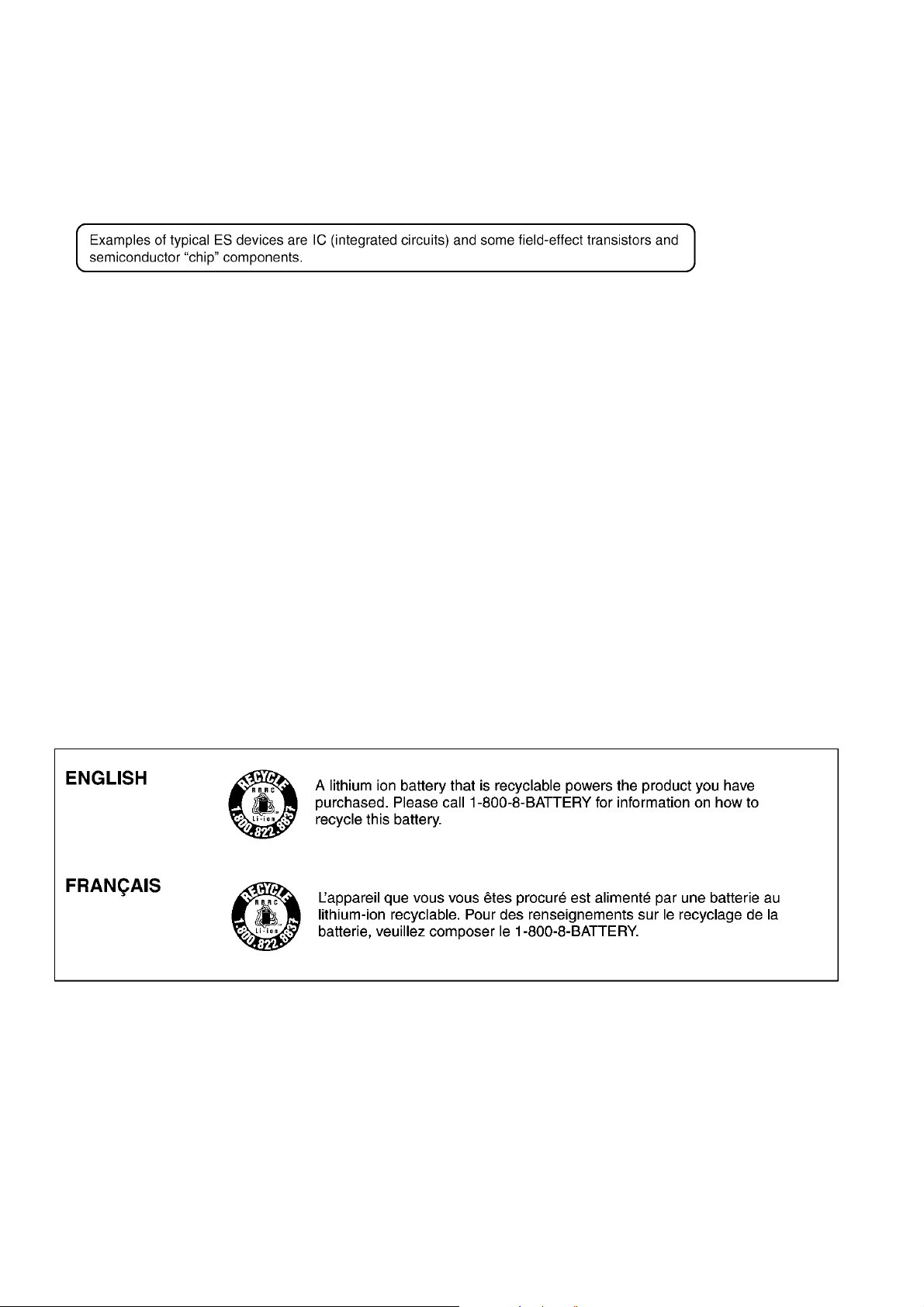
2.2. How to Recycle the Lithium Ion Battery (U.S. Only)
6
Page 7
2.3. Caution for AC Cord
(For EB/GC/GH)
2.3.1. Information for Your Safety
IMPORTANT
Your attention is drawn to the fact that recording of prerecorded tapes or discs or other published or broadcast
material may infringe copyright laws.
WARNING
To reduce the risk of fire or shock hazard, do not expose
this equipment to rain or moisture.
CAUTION
To reduce the risk of fire or shock hazard and annoying
interference, use the recommended accessories only.
FOR YOUR SAFETY
DO NOT REMOVE THE OUTER COVER
To prevent electric shock, do not remove the cover. No user
serviceable parts inside. Refer servicing to qualified service
personnel.
2.3.2. Caution for AC Mains Lead
For your safety, please read the following text carefully.
This appliance is supplied with a moulded three-pin mains plug
for your safety and convenience.
A 5-ampere fuse is fitted in this plug.
Should the fuse need to be replaced please ensure that the
replacement fuse has a rating of 5 amperes and it is approved
by ASTA or BSI to BS1362
Check for the ASTA mark or the BSI mark on the body of the
fuse.
2.3.2.1. Important
The wires in this mains lead are coloured in accordance with
the following code:
Blue Neutral
Brown Live
As the colours of the wires in the mains lead of this applianc e
may not correspond with the coloured markings identifying the
terminals in your plug, proceed as follows:
The wire which is coloured BLUE must be connected to the terminal in the plug which is marked with the letter N or coloured
BLACK.
The wire which is coloured BROWN must be connected to the
terminal in the plug which is marked with the letter L or coloured
RED.
Under no circumstances should either of these wi res be connected to the earth terminal of the three pin plug, marked with
the letter E or the Earth Symbol.
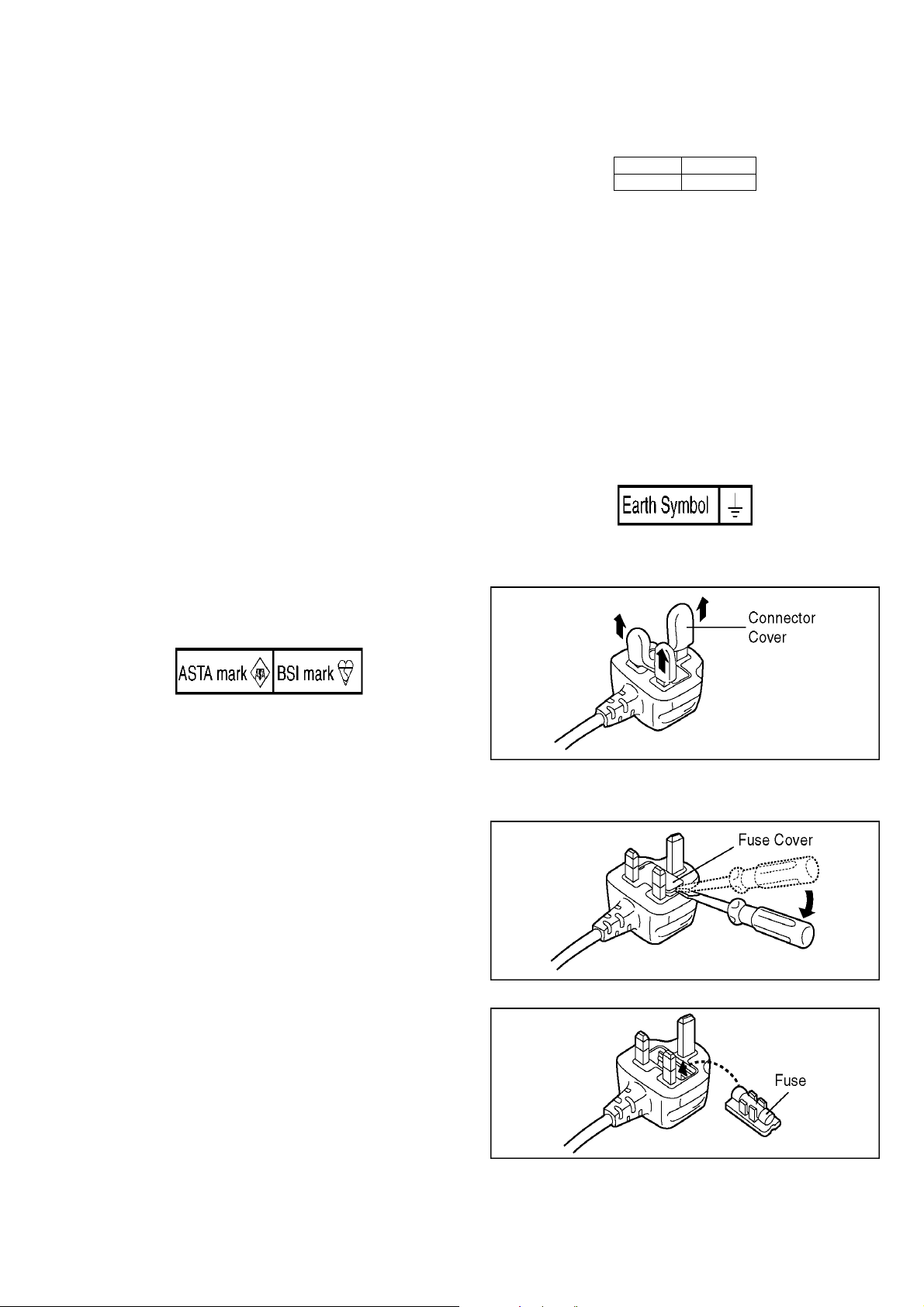
2.3.2.2. Before Use
Remove the Connector Cover as follows.
If the plug contains a removable fuse cover you must ensure
that it is refitted when the fuse is replaced.
If you lose the fuse cover, the plug must not be used until a
replacement cover is obtained.
A replacement fuse cover can be purchased from your local
Panasonic Dealer.
If the fitted moulded plug is unsuitable for the socket outlet in
your home then the fuse should be removed and the plug cut
off and disposed of safety.
There is a danger of severe electrical shock if the cut off plug is
inserted into any 13-ampere socket.
If a new plug is to be fitted please observe the wiring code as
shown below.
If in any doubt, please consult a qualified electrician.
2.3.2.3. How to Replace the Fuse
1. Remove the Fuse Cover with a screwdriver.
2. Replace the fuse and attach the Fuse cover.
7
Page 8
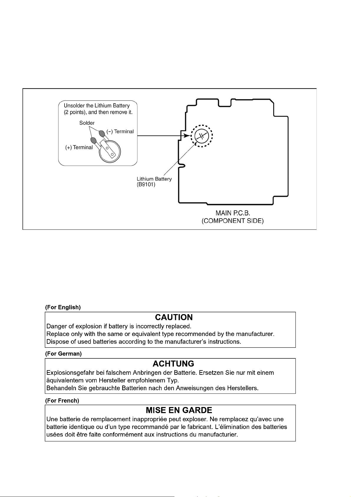
2.4. How to Replace the Lithium Battery
2.4.1. Replacement Procedure
1. Remove the MAIN P.C.B.. (Refer to Disassembly Procedures.)
2. Unsolder the each soldering point of electric l ead terminal for Lithium battery (Ref. No. “B9101” at component side of MAIN
P.C.B.) and remove the Lithium battery together with electric lead terminal. Then replace it into new one.
NOTE:
The Type No. ML421 includes electric lead terminals.
NOTE:
This Lithium battery is a critical component.
(Type No.: ML421 Manufactured by Energy Company, Panaso nic Corporation.)
It must never be subjected to excessive heat or discharge.
It must therefore only be fitted in requirement designed specifically for its use.
Replacement batteries must be of same type and manufacture.
They must be fitted in the same manner and location as the original battery, with the correct polarity contacts observed.
Do not attempt to re-charge the old battery or re-use it for any other purpose.
It should be disposed of in waste products destined for burial rather than incineration.
NOTE:
Above caution is applicable for a battery pack which is for DMC-FP1,FP2 series, as well.
8
Page 9
3 Service Navigation
3.1. Introduction
This service manual contains technical information, which allow service personnel’s to understand and service this model.
Please place orders using the parts list and not the drawing reference numbers.
If the circuit is changed or modified, the information will be followed by service manual to be controlled with original service manual.
3.2. General Description About Lead Free Solder (PbF)
The lead free solder has been used in the mounting proce ss of a ll electrical components on the printed circuit board s used for this
equipment in considering the globally environmental conservation.
The normal solder is the alloy of tin (Sn) and lead (Pb). On the other hand, the lead free solder is the alloy mainly consists of tin
(Sn), silver (Ag) and Copper (Cu), and the melting point of the lead free solder is higher approx.30°C (86°F) more than that of the
normal solder.
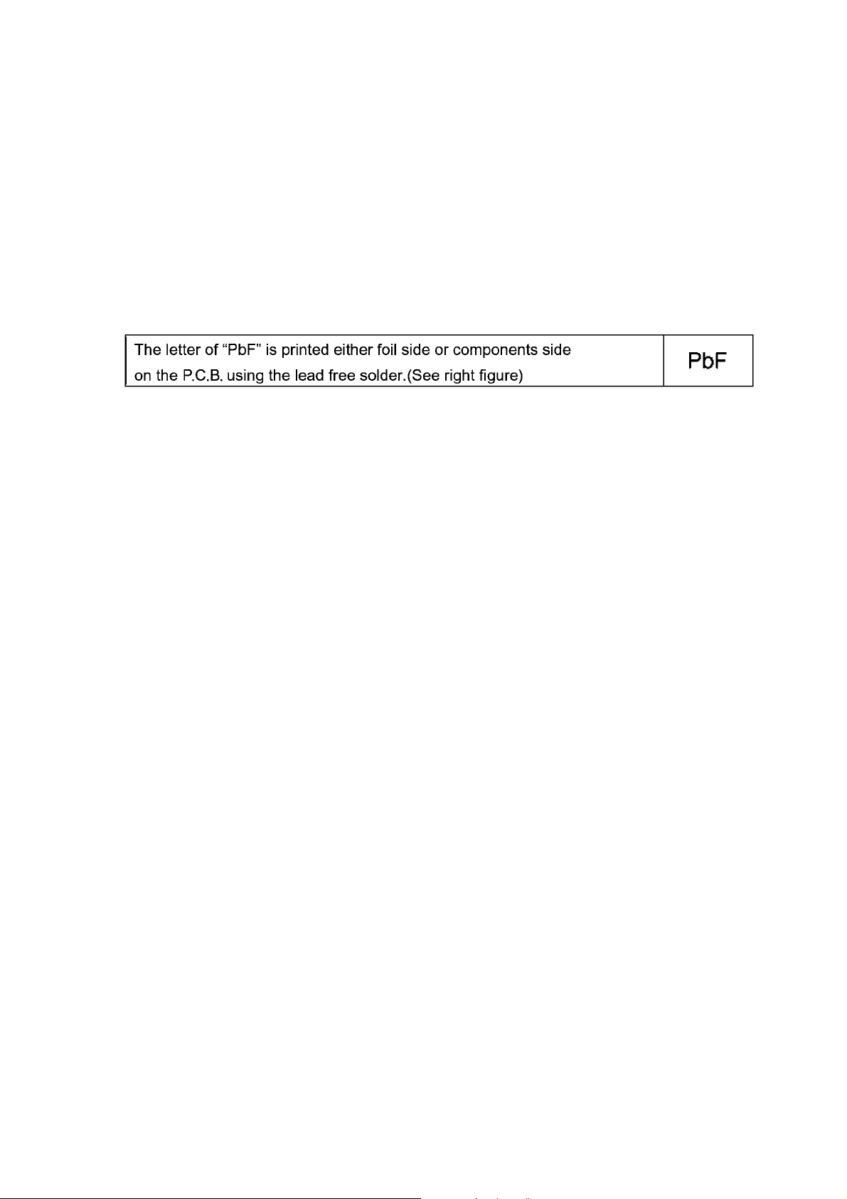
Distinction of P.C.B. Lead Free Solder being used
Service caution for repair work using Lead Free Solder (PbF)
• The lead free solder has to be used when repairing the equipment for which the lead free solder is used.
(Definition: The letter of “PbF” is printed on the P.C.B. using the lead free solder.)
• To put lead free solder, it should be well molten and mixed with the original lead free solder.
• Remove the remaining lead free solder on the P.C.B. cleanly for sold ering of the new IC.
• S ince the melting point of the lead free solder is higher tha n that of the normal lead solder, it takes the longer time to melt the
lead free solder.
• Use the soldering iron (more than 70W) equipped with the temperature control after setting the temperature at 350±30°C
(662±86°F).
Recommended Lead Free Solder (Service Parts Route.)
• The following 3 types of lead free solder are available through the service parts route.
RFKZ03D01KS-----------(0.3mm 100g Reel)
RFKZ06D01KS-----------(0.6mm 100g Reel)
RFKZ10D01KS-----------(1.0mm 100g Reel)
Note
* Ingredient: tin (Sn) 96.5%, silver (Ag) 3.0%, Copper (Cu) 0.5%, Cobalt (Co) / Germanium (Ge) 0.1 to 0.3%
3.3. Important Notice 1:(Other than U.S.A. and Canadian Market)
1. The service manual does not contain the following information because of issues servicing to component level without necessary equipment/facilities.
a. Schematic diagram, Block Diagram and P.C.B. layout of MAIN P.C.B. and SUB OPERATION P.C.B..
b. Parts list for individual parts for MAIN P.C.B. and SUB OPERATION P.C.B..
When a part replacement is required for repairing MAIN P.C.B. and/or SUB OPERATION P.C.B., replace as an assembled
parts. (MAIN P.C.B. / SUB OPERATION P.C.B.)
2. The following category is/are recycle module part. please send it/them to Central Repair Center.
• MAIN P.C.B. (DMC-FP1: VEP56095B, DMC-FP2: VEP56095C)
• SUB OPERATION P.C.B. (VEP59074A)
9
Page 10
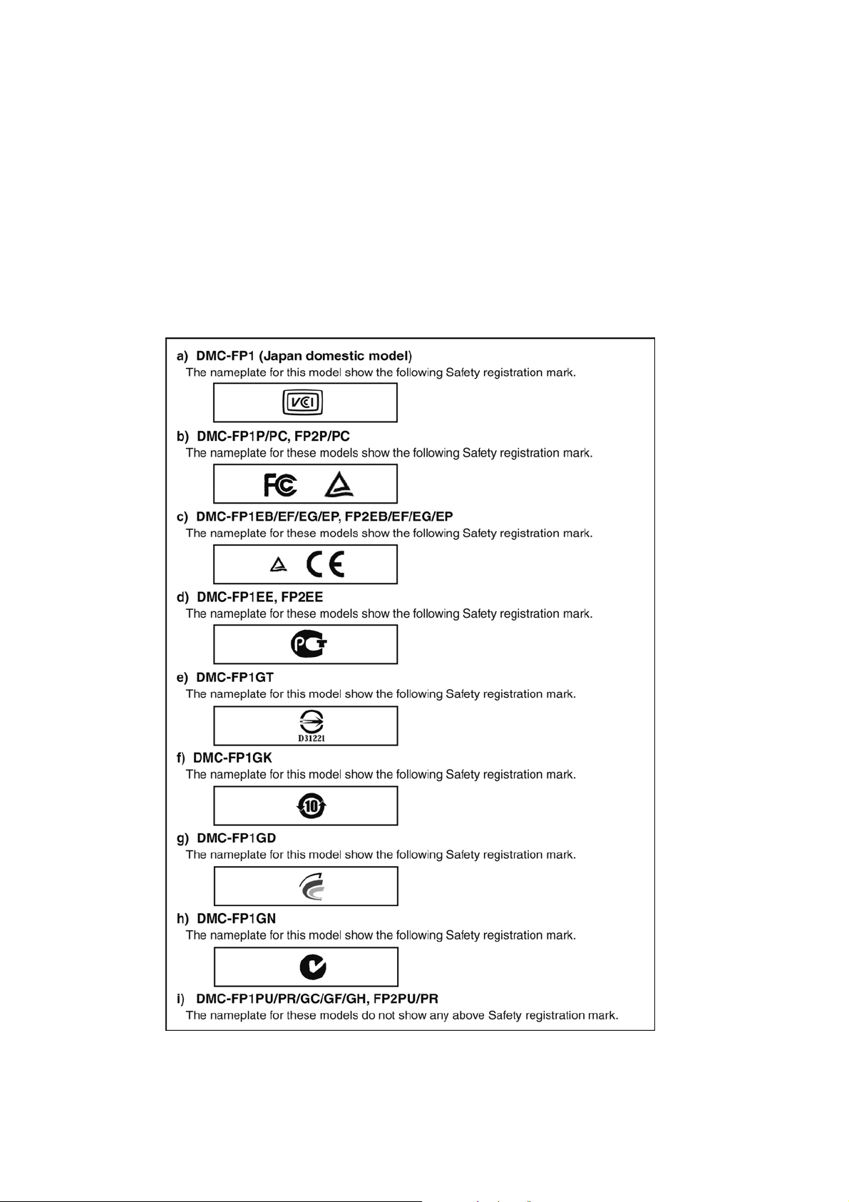
3.4. How to Define the Model Suffix (NTSC or PAL model)
There are nine kinds of DMC-FP1/FP2, regardless of the colours.
• a) DMC-FP1 (Japan domestic model)
• b) DMC-FP1P/PC, FP2P/PC
• c) DMC-FP1EB/EF/EG/EP, FP2EB/EF/EG/EP
• d) DMC-FP1EE, FP2EE
• e) DMC-FP1GT
• f) DMC-FP1GK
• g) DMC-FP1GD
• h) DMC-FP1GN
• i) DMC-FP1PU/PR/GC/GF/GH, FP2PU/PR
What is the difference is that the “INITIAL SETTINGS” data which is stored in Flash-ROM mounted on MAIN P.C.B..
3.4.1. Defining methods:
To define the model suffix to be serviced, refer to the nameplate which is putted on the bottom side of the Unit.
NOTE:
After replacing the MAIN P.C.B., be sure to achieve adjustment.
The adjustment instruction is available at “software download” on the “Support Information from NWBG/VDBG-AVC” web-site in
“TSN system”, together with Maintenance software.
10
Page 11
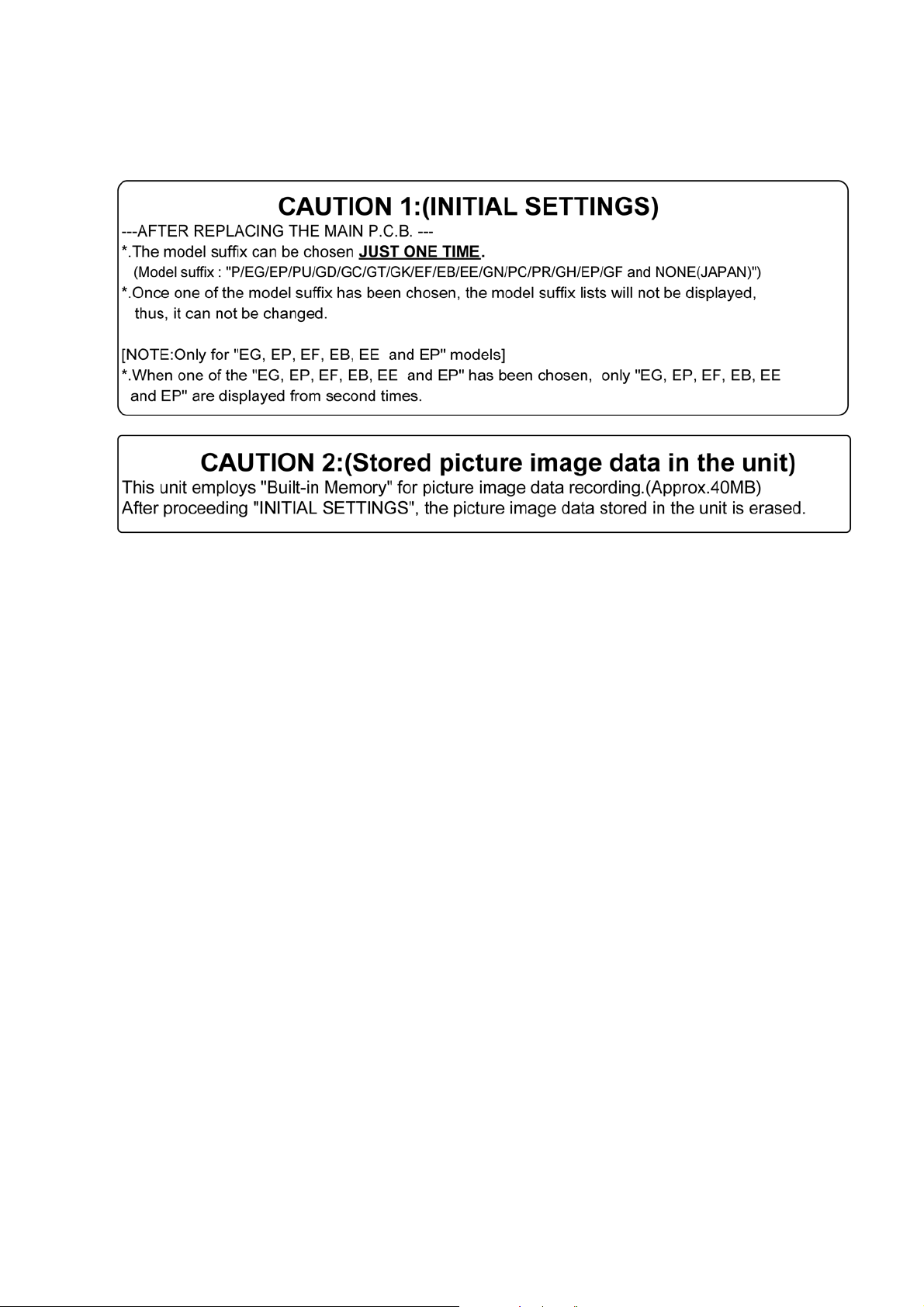
3.4.2. INITIAL SETTINGS:
After replacing the MAIN P.C.B., be sure to perform the initial settings after achieving the adjustment by or dering the fo llowi ng procedure in accordance with model suffix of the unit.
1. IMPORTANT NOTICE:
Before proceeding Initial settings, be sure to read the following CAUTIONS.
2. PROCEDURES:
• P recautions: Read the above "CAUTION 1" and "CAUTION 2", carefully.
• Preparation:
1. Attach the Battery or AC Adaptor with a DC coupler to the unit.
(Since this unit has built-in memory, it can be performed without inserting SD memory card.)
2. Set the recording mode to the [ NORMAL PICTURE ] mode.
(Press the [ MODE ] button and select the [ NORMAL PICTURE ] by pressing the “[ UP ] and [ DOWN ] of Cursor buttons”,
then press the [ MENU/SET ] button.)
NOTE:
If the unit is other than [ NORMAL PICTURE ] mode, it does not display the initial settings menu.
• Step 1. The temporary cancellation of “INITIAL SETTINGS”:
While keep pressing “[ UP ] of Cursor button” and [ iA ] button simultaneously, turn the Power on.
• Step 2. The cancellation of “INITIAL SETTINGS”:
Press the [ PLA YBACK ] button to “Playback Mode”.
Press “[ UP ] of Cursor button” and [ iA ] button simultaneously, then turn the Power off.
• Step 3. Turn the Power on:
Turn the Power on.
• Step 4. Display the INITIAL SETTING:
While keep pressing [ MENU/SET ] and “[ RIGHT ] of Cursor buttons” simultaneously, turn the Power off.
The "INITIAL SETTINGS" menu is displayed.
There are two kinds of “INITIAL SETTINGS” menu form as follows:
11
Page 12
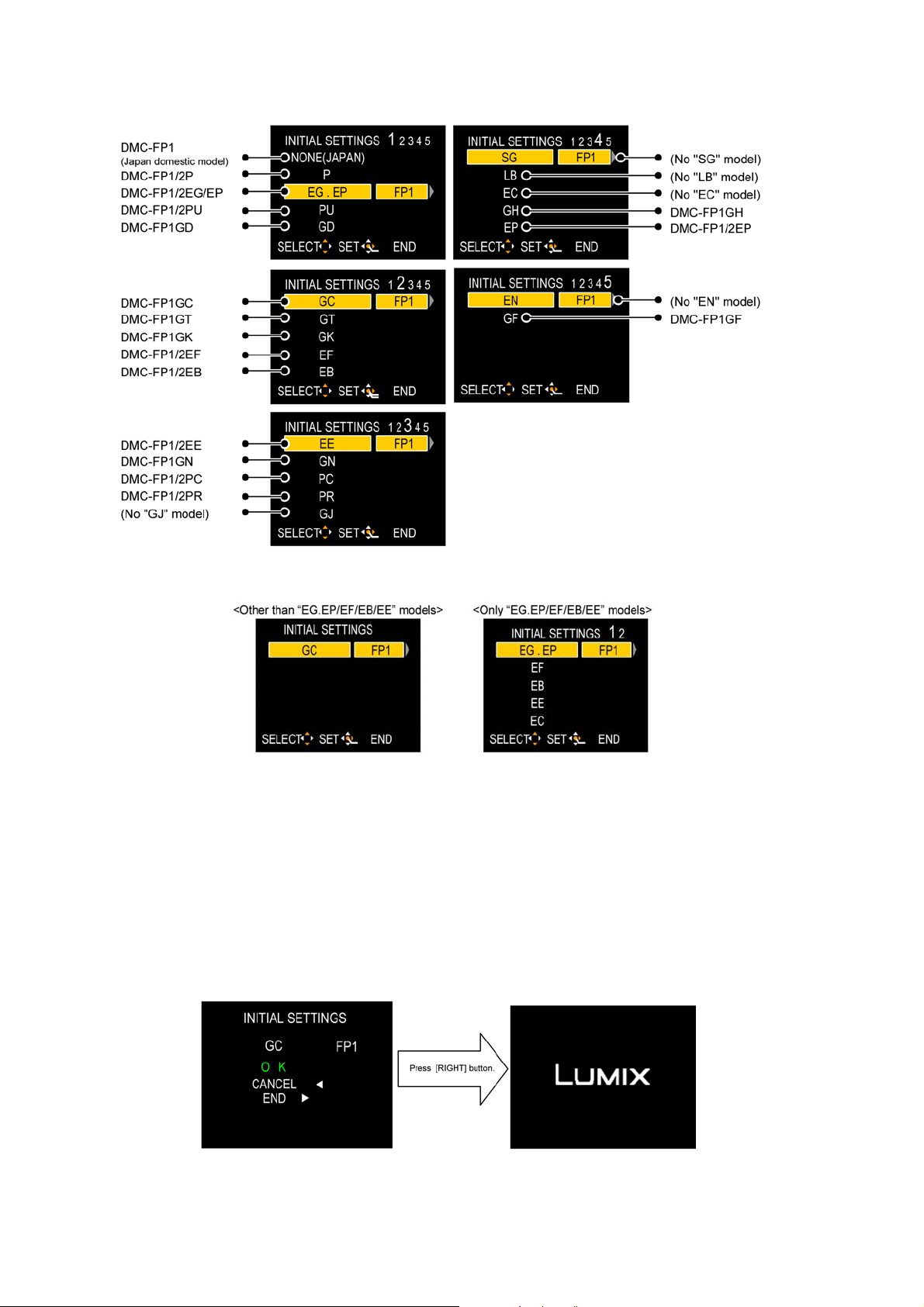
[CASE 1. After replacing MAIN P.C.B.]
When MAIN P.C.B. has just been replaced, all of the model suffix is displayed as follows. (Five pages in total)
[CASE 2. Other than “After replacing MAIN P.C.B.”]
• Step 5. Choose the model suffix in “INITIAL SETTINGS”: (Refer to “CAUTION 1”)
[Caution: After replacing MAIN P.C.B.]
The model suffix can been chosen, JUST ONE TIME.
Once one of the model suffix have been chosen, the model suffix lists will not be displayed, thus, it can not be changed.
Therefore, select the area carefully.
Select the area with pressing “[ UP ] / [ DOWN ] of Cursor buttons”.
• Step 6. Set the model suffix in “INITIAL SETTINGS”:
• Press the “[ RIGHT ] of Cursor buttons”.
• The only set area is displayed, and then press the “[ RIGHT ] of Cursor buttons” after confirmation.
(The unit is powered off automatically.)
12
Page 13

• Step 7. CONFIRMATION:
Confirm the display of “PLEASE SET THE CLOCK” in concernd language when the unit is turned on again.
When the unit is connected to PC with USB cable, it is detected as removable media.
1) As for your reference, major default setting condition is as shown in the following table.
• Default setting (After “INITIAL SETTINGS”)
MODEL VIDEO OUTPUT LANGUAGE DATE REMARKS
a) DMC-FP1 (Japan domestic model) NTSC Japanese Year/Month/Date
b) DMC-FP1/FP2P NTSC English Month/Date/Year
c) DMC-FP1/FP2EG PAL English Date/Month/Year
d) DMC-FP1/FP2EP PAL English Date/Month/Year
e) DMC-FP1/FP2PU NTSC English Month/Date/Year
f) DMC-FP1GD NTSC Korean Year/Month/Date
g) DMC-FP1GC PAL English Date/Month/Year
h) DMC-FP1GT NTSC Chinese (traditional) Year/Month/Date
i) DMC-FP1GK PAL Chinese (simplified) Year/Month/Date
j) DMC-FP1/FP2EF PAL French Date/Month/Year
k) DMC-FP1/FP2EB PAL English Date/Month/Year
l) DMC-FP1/FP2EE PAL Russian Date/Month/Year
m) DMC-FP1GN PAL English Date/Month/Year
n) DMC-FP1/FP2PC NTSC English Month/Date/Year
o) DMC-FP1/FP2PR PAL English Date/Month/Year
p) DMC-FP1GH PAL English Date/Month/Year
q) DMC-FP1GF PAL English Date/Month/Year
13
Page 14
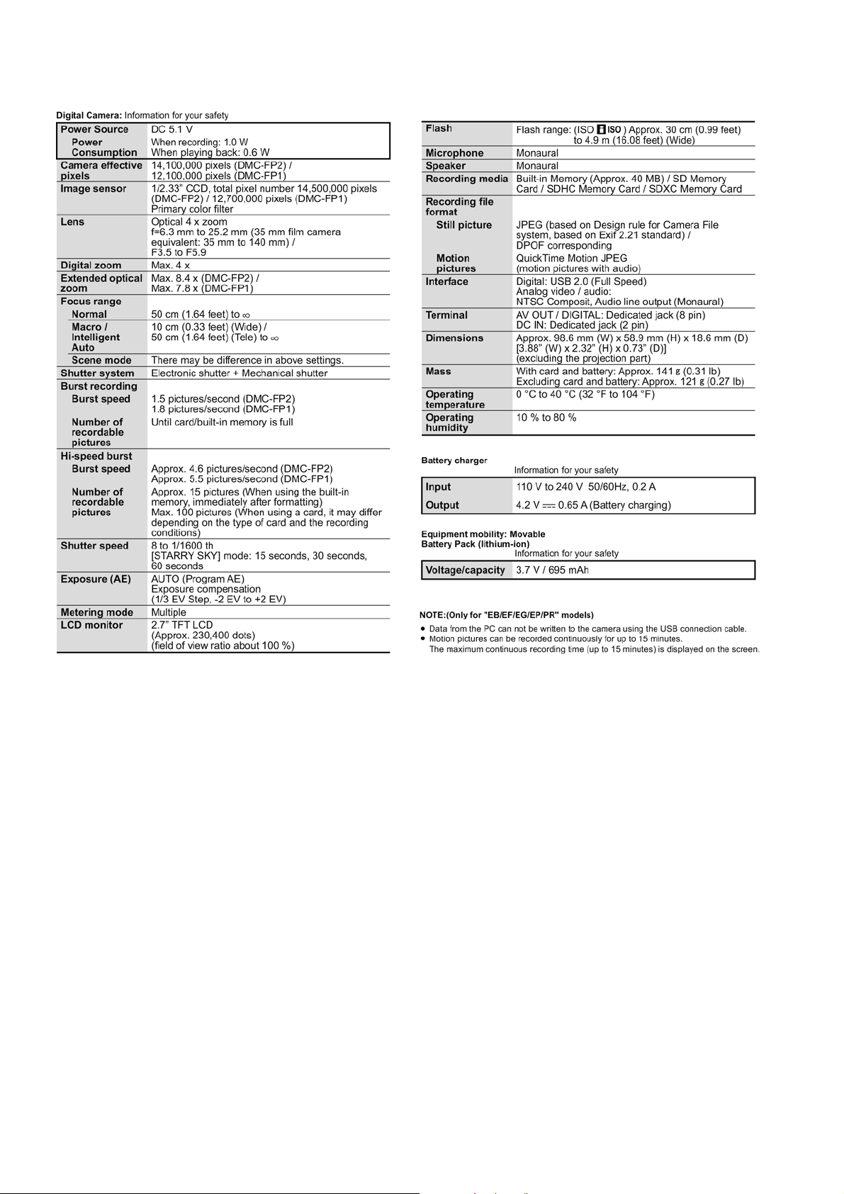
4 Specifications
14
Page 15
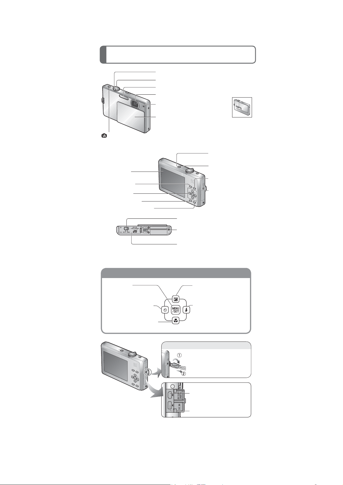
5 Location of Controls and Components
Hand strap eyelet
Cursor button
Names of parts
Zoom lever
Shutter button
Flash
Lens
Self-timer indicator/
AF assist lamp
Lens cover
Fully peel off the strip of tape from the
lens cover before using the camera.
button
When opening and closing the lens
cover, make sure that liquid or foreign
objects such as sand do not enter.
Microphone
LCD monitor
[MODE] button
Cursor button
[DISPLAY] button
[Q.MENU]/delete button
Release lever
Tripod receptacle
Ensure that the tripod is stable.
Card/Battery door
We recommend you use a battery with sufficient battery power or the
Ɣ
AC adaptor when recording motion pictures.
[MENU/SET]
(menu display/set/finish)
/HIWFXUVRUEXWWRQŻ
Self-timer
'RZQFXUVRUEXWWRQź
Macro mode
Power button
Playback button
Speaker
8SFXUVRUEXWWRQŸ
Exposure compensation
5LJKWFXUVRUEXWWRQŹ
Flash
We recommend using the
supplied hand strap to avoid
dropping the camera.
[AV OUT/DIGITAL] socket
[DC IN] socket
Always use a genuine Panasonic AC adaptor (DMW-AC5PP: optional).
Ɣ
If while recording motion pictures using the AC adaptor the power
Ɣ
supply is cut off due to a power cut or if the AC adaptor is disconnected
etc., the motion picture being recorded will not be recorded.
15
Page 16
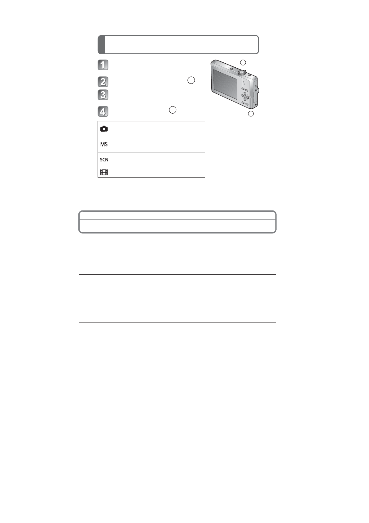
Selecting the [REC] mode
Open the lens cover
The power is turned on.
Press the [MODE] button (
)
A
A
3UHVVŸRUźWRVHOHFWWKH
recording mode
Press [MENU/SET] (
[NORMAL PICTURE] Mode
Take pictures with your own settings.
[MY SCENE MODE]
Take pictures in commonly used scene
modes.
[SCENE MODE]
Take pictures according to scene.
[MOTION PICTURE] Mode
Take motion pictures.
Preparation
)
B
B
About the Battery
The camera has a function for distinguishing batteries which can be used safely. The
dedicated battery supports this function. The only batteries suitable for use with this
unit are genuine Panasonic products and batteries manufactured by other companies
and certified by Panasonic. (Batteries which do not support this function cannot be
used). Panasonic cannot in any way guarantee the quality, performance or safety of
batteries which have been m
Panasonic products.
It has been found that counterfeit battery packs which look very similar to the
genuine product are made available to purchase in some markets. Some of these
battery packs are not adequately protected with internal protection to meet the
requirements of appropriate safety standards. There is a possibility that these
battery packs may lead to fire or explosion. Please be advised that we are not
liable for any accident or fa
battery pack. To ensure that safe products are used we would recommend that a
genuine Panasonic battery pack is used.
anufactured by other companies and are not genuine
ilure occurring as a result of use of a counterfeit
16
Page 17

6 Service Mode
6.1. Error Code Memory Function
1. General description
This unit is equipped with history of error code memory function, and can be memorized 16 error codes in sequence from the
latest. When the error is occurred more than 16, the oldest error is overwritten in sequence.
The error code is not memorized when the power supply is shut down forcibly. (i.e.,when the unit is powered on by the battery,
the battery is pulled out) The error code is memorized to FLASH-ROM when the unit has just before power ed off.
2. How to display
The error code can be displayed by ordering the following procedure:
• Preparation:
1. Attach the Battery or AC Adaptor with a DC coupler to the unit.
NOTE:
*Since this unit has built-in memory, it can be performed without inserting SD memory card.
*It is not a matter or the setting condition of Recording mode (such as “normal picture/scene/motion picture” mode) to display
the error code.
• Step 1. The temporary cancellation of “INITIAL SETTINGS”:
While keep pressing “[ UP ] of Cursor button” and [ iA ] button simultaneously, turn the Power on.
• Step 2. Execute the error code display mode:
Press the “[ LEFT ] of Cursor button”, [ MENU/SET ] button and [ iA ] button simultaneously.
The display is changed as shown below when the above buttons are pressed simultaneously.
Normal display → Error code display → Operation history display → Normal display → .....
Example of Error Code Display
17
Page 18

• 3. Error Code List
The error code consists of 8 bits data and it shows the following information.
18
Page 19

Important notice about "Error Code List"
1) About "*" indication:
The third digit from the left is different as follows.
- In case of 0 (example: 180
When the third digit from the left shows "0", this error occurred under the condition of INITIAL SETTINGS has been
completed.
It means that this error is occurred basically at user side.
- In case of 8 (example: 188
When the third digit from the left shows "8", this error occurred under the condition of INITIAL SETTINGS h as been
released.
(Example; Factory assembling-line before unit shipment, Service mode etc.)
It means that this error is occurred at service side.
2) About "?" indication: ("18*0 0?01" to "18*0 0?50"):
The third digit from the right shows one of the hexadecimal ("0" to "F") character.
• 4. How to exit from Error Code display mode:
Simply, turn the power off. (Since Error code display mode is executed under the condition of temporary cancellation of "INITIAL SETTINGS", it wake up with normal condition when turn off the power.)
NOTE:
The error code can not be initialized.
01000)
01000)
6.2. ICS (Indication of additional Camera Settings when picture was taken)
function
1. General description
This unit is equipped with ICS (ICS: Indication of additional Camera Settings when picture was taken) function by playing back
the concerned picture on the LCD display.
(This function is achieved by utili z i ng "maker note" data stored in Exif data area of recorded picture file. )
To proceed failure dia gnosis, use this ICS function together with "displaying the recorded picture with picture information "
function.
NOTE:
• The ICS function operates with a picture which is only taken with the same model. (It may not be displayed when the picture
was taken with other model.)
• Since Exif data is not available after the picture is edited by PC, the ICS function may not be activated.
2. How to display
The ICS data is displayed by ordering the following procedure:
• Preparation:
1. Attach the Battery or AC Adaptor with a DC coupler to the unit.
NOTE:
It is not a matter or the setting condition of Recording mode (such as “n ormal pictu re/sce ne/motion p icture” mode ) to displ ay
the ICS data.
• Step 1. The temporary cancellation of "INITIAL SETTINGS":
While keep pressing “[ UP ] of Cursor button” and [ iA ] button simultaneously, turn the Power on.
• Step 2. Execute the ICS display mode:
Press the [ PLAYBACK ] button to “Playback Mode”.
Select the concerned picture by pressing the "[ LEFT ] and [ RIGHT ] of Cursor button".
Press the "[ LEFT ] of Cursor button", [ MENU/SET ] button and [ iA ] button simultaneously.
Press the [ DISPLAY ] button, 3 times.
The display condition is changed as shown below when the [ DISPLAY ] button is pressed.
Code display → Code + Picture display (1) → Code + Picture display (2) → ICS display → Code display .....
19
Page 20

3. How to read
4. How to exit:
Simply, turn the power off. (Since ICS function is executed under the condition of temporary cancellation of
"INITIAL SETTINGS", it wake up with normal condition when turn off the power.)
20
Page 21

7 Service Fixture & Tools
7.1. Service Fixture and Tools
The following Service Fixture and tools are used for checking and servicing this unit.
21
Page 22

7.2. When Replacing the Main P.C.B.
After replacing the MAIN P.C.B., be sure to achieve adjustment.
The adjustment instruction is available at “software download” on th e “Support Information from NWBG/VDBG-AVC” web-site in
“TSN system”, together with Maintenance software.
7.3. Service Position
This Service Position is used for checking and replacing parts. Use the following Extension cables for servicing.
Table S1 Extension Cable List
No. Parts No. Connection Form
1 RFKZ0416 FP9003 (MAIN) - LCD UNIT 41PIN 0.3 FFC
2 RFKZ0418 PP9001 (MAIN) - PS8001 (FLASH TOP) 30PIN B to B
3 RFKZ0548 PS9001 (MAIN) - PP9501 (SUB OPERATION) 20PIN B to B
CAUTION-1. (When servicing E.Capacitor P.C.B.)
1. Be sure to discharge the capacitor on E.Capacitor P.C.B..
Refer to “HOW TO DISCHARGE THE CAPACITOR ON E.Capacitor P.C.B.”.
The capacitor voltage is not lowered soon even if the AC Cord is unplugged or the battery is removed.
2. Be careful of the high voltage circuit on E.Capacitor P.C.B..
3. DO NOT allow other parts to touch the high voltage circuit on E.Capacitor P.C.B..
22
Page 23

8 Disassembly and Assembly Instructions
8.1. Disassembly Flow Chart
This is a disassembling chart.
When assembling, perform this chart conversely.
8.2. PCB Location
23
Page 24

8.3. Disassembly Procedure
No. Item Fig Removal
1 Rear Case Unit (Fig. D1) Card
Battery
1 Screw (A)
4 Screws (B)
2 Screws (C)
Side Ornament L1
Side Ornament L2
(Fig. D2) Side Ornament (R)
1 Screw (D)
2 Locking tabs
Rear Case Unit
2 Front Case Unit (Fig. D3) 1 Screw (E)
Strap Holder
Front Case Unit
3 Lens Cover (Fig. D4) 3 Screws (F)
2 Hanging parts
(Fig. D5) 1 Screw (G)
Lens Cover Spring
Lens Cover Angle
Lens Cover Slide Angle
Lens Cover
4 Sub Operation P.C.B. (Fig. D6) PP9501(Connector)
Sub Operation P.C.B.
5 LCD Unit (Fig. D7) 2 Locking tabs
PCB Spacer
1 Screw (H)
(Fig. D8) FP9003(Flex)
LCD Unit
6 Top Operation Unit (Fig. D9) 2 Screws (I)
Frame Plate
PS8001(Connector)
Top Operation Unit
7 E.Capacitor P.C.B. (Fig. D10) 1 Screw (J)
1 Hanging part
1 Locking tab
Capacitor Holder
E.Capacitor P.C.B.
(Fig. D11) Discharge the Capacitor
8 Flash Top P.C.B. (Fig. D12) 1 Screw (K)
1 Locking tab
(Fig. D13) Mic Damper
POWER Knob
IA Knob
Flash Top P.C.B.
9 Lens Unit (with CCD) (Fig. D14) FP9001(Flex)
FP9002(Flex)
Lens Unit
10 Lens Switch P.C.B.
Main P.C.B.
11 Jack Door (Fig. D16) Jack Door Shaft
12 Battery Case Unit (Fig. D17) Battery Out Spring
13 Battery Door Unit (Fig. D19) Battery Door Shaft
(Fig. D15) 1 Locking tab
Speaker
1 Screw (L)
Lens Switch P.C.B.
Main P.C.B.
Jack Door
2 Locking tabs
(Fig. D18) Battery Case Unit
Battery Door Spring
Battery Door Unit
8.3.1. Removal of the Rear Case Unit
(Fig. D1)
24
Page 25

8.3.2. Removal of the Front Case Unit
(Fig. D2)
(Fig. D3)
8.3.3. Removal of the Lens Cover
25
(Fig. D4)
Page 26

8.3.4. Removal of the Sub Operation
P.C.B.
(Fig. D6)
8.3.5. Removal of the LCD Unit
(Fig. D5)
(Fig. D7)
26
Page 27

(Fig. D8)
8.3.6. Removal of the Top Operation Unit
27
(Fig. D9)
Page 28

8.3.7. Removal of the E.Capacitor P.C.B.
(Fig. D10)
(Fig. D11)
8.3.8. Removal of the Flash Top P.C.B.
(Fig. D12)
28
Page 29

(Fig. D13)
8.3.9. Removal of the Lens Unit (with
CCD)
NOTE:
When Disassembling and Assembling for the Lens Unit
1. Take care that the dust and dirt are not entered into the
lens. In case of the dust is putted on the lens, blow off
them by airbrush.
2. Do not touch the surface of lens.
3. Use lens cleaning KIT(BK) (VFK1900BK).
8.3.10. Removal of the Lens Switch P.C.B.
and Main P.C.B.
(Fig. D14)
(Fig. D15)
8.3.1 1. Removal of the Jack Door
(Fig. D16)
29
Page 30

8.3.12. Removal of the Battery Case Unit
8.3.13. Removal of the Battery Door Unit
(Fig. D17)
(Fig. D19)
NOTE: (When Assembling)
Make sure to confirm the following points when assembling:
• The Screw is tightened enough.
• A ssembling conditions are fine. (No distortion, no ab normalspace.)
• No dust and/or dirt on Lens surfaces.
• LCD image is fine. (No dust and dirt on it, and no gradient
images.)
(Fig. D18)
30
Page 31

9 Measurements and Adjustments
9.1. Introduction
When servicing this unit, make sure to perform the adjustments necessary based on the part(s) replaced.
Before disassembling the unit, it is recommended to back up the camera data stored in flash-rom as a data file.
IMPORT ANT NOTICE (After replacing the MAIN P.C.B.)
After replacing the MAIN P.C.B., it is necessary to use the “DIAS” software to allow the release of adjustme nt flag(s).
The Adjustment software “DIAS” is available at “TSN Website”. To download, click on “Support Info rmati on from NWBG/VD BGAVC”.
*DIAS (DSC Integrated Assist Software)
9.2. Before Disassembling the unit
9.2.1. Initial Setting Release
The cameras specification are initially set in accordance with model suffix (such as EB, EG, GK, GC, and so on.).
Unless the initial setting is not released, an automatic alignment software in the camera is not able to be executed w hen the alignment is carried out.
Note:
The initial setting should be again done after completing the alignment. Otherwise, the camera may not work properly.
Therefore as a warning, the camera display a warning symbol “ ! ” on the LCD monitor every time the camera is turned off.
Refer to the procedure described in “3.4.2 INITIAL SETTINGS” for details.
[ How to Release the camera initial setting ]
Preparation:
1. Attach the Battery or AC Adaptor with a DC coupler to the unit.
(Since this unit has built-in memory, it can be performed without inserting SD memory card.)
2. Set the recording mode to the [ NORMAL PICTURE ] mode.
(Press the [ MODE ] button and select the [ NORMAL PICTURE ] by pressing the “[ UP ] and [ DOWN ] of Cursor button s”,
then press the [ MENU/SET ] button.)
Step 1. Temporary cancellation of “INITIAL SETTINGS”:
While keep pressing “[ UP ] of Cursor button” and [ iA ] button simultaneously, turn the Power on.
Step 2. Cancellation of “INITIAL SETTINGS”:
Press the [ PLAYB A CK ] button to “Playback Mode”.
Press “[ UP ] of Cursor button” and [ iA ] button simultaneously. (The camera will beep after this.)
Turn the Power off. (The warning symbol “ ! ” is displayed on the LCD monitor.)
31
Page 32

9.2.2. Flash-Rom Data Backup
When trouble occurs, it is recommended to backup the Flash-rom data before disassembling the unit.
There are two kinds of Flash-rom data backup methods:
[ ROM_BACKUP (Method of Non-PC backup) ]
1. Insert the SD-card into the camera.
2. Set the camera to “Temporary cancellation of the initial
settings”.
3. Select the “SETUP” menu.
From the “SETUP” menu, select “ROM BACKUP”.
NOTE:
This item is not listed on the customer's “SETUP”
menu.
4. When this “ROM_BACKUP” item is selected, the following submenus are displayed.
[ DSC Integrated Assist Software (Method of Using PC) ]
Same as TATSUJIN software for previous models.
9.2.3. Light Box
If using VFK1164TDVLB Light Box, remove the lens connection
ring by loosing three hexagon screws.
32
Page 33

9.3. Details of Electrical Adjustment
9.3.1. How to execute the Electrical Adjustment
It is not necessary to connect the camera to a PC to perform adjustments.
“Flag reset operation” and “Initial setting operation” are required when carrying out the alignment, follow the procedure below.
9.3.1.1. Startup Electrical Adjustment mode
1. Release the initial settings.
2. Insert a recordable SD card.
(Without a SD card, the automatic adjustment can not
executed.)
3. Procedure to set the camera into adjustment mode:
a. Set the mode into [ NORMAL PICTURE ] mode.
b. Turn the Power off.
c. Turn the Power on pressing [ DISPLAY ] and [ MENU/
SET ] simultaneously.
LCD monitor displays “SERVICE MODE”.(Refer to
Fig. 3-1)
9.3.1.2. Status Adjustment Flag Setting
Reset (Not yet adjusted) the status flag condition.
1. After pressing the [ DISPLAY ] button, the LCD monitor
displays the Flag status screen (Refer to Fig.3-2)
2. Select item by pressing the Cursor buttons. (Gray cursor
is moved accordingly.)
3. Press the [ Delete ] button.
NOTE:
The selected item's flag has been changed from
“F (green)” to “0 (yellow)”.
*(Refer to Fig. 3-3)
*Flag conditions:
F (green)
means that the alignment has been completed and the
status flag condition is set. In this case, the flag condition
should be reset, if you try to carry out the automatic alignment.
0 (yellow)
means that the alignment has been not “completed” and
the status flag condition is “reset”. In this case, automatic
alignment is available.
• I n case of setting the status flag into set condition aga in without completion of the alignment, the status flag should be SET by
using PC, or UNDO by using ROM BACKUP function.
33
Page 34

9.3.1.3. Execute Adjustment
(In case of “OIS Adjustment”)
1. Perform step “9.3.1.1.” to “9.3.1.2.”, to reset the OIS flag
status “F” (Set) to “0” (Reset)
2. Press [ DISPLAY ] button after Flag reset.
OIS Adjustment screen is displayed on the LCD panel.
(Refer to Fig.3-4)
3. Press the [ Shutter ] button. The adjustment will start
automatically.
4. When the adjustment is completed successfully, adjustment report menu appears with Green OK on the LCD
monitor. (Refer to Fig.3-5)
9.3.1.4. Attention point during Adjustment
1. Step “9.3.1.3.” procedure shows OIS adjustment as an
example. To perform the adjustment, refer to the “9.3.2.
Adjustment Specifications” table which shows key point
for each adjustment.
2. Do not move the light box, the camera or the chart while
adjusting. If one of these is moved accidentally, start the
adjustment again.
3. Do not press any buttons/keys until the default menu
(Fig.3-6) is displayed on the LCD monitor. Otherwise,
adjustment data may not be stored properly.
4. If the adjustment is interrupted accidentally, the alignment
data may not be properly saved in the Flash-rom.
9.3.1.5. Finalizing the Adjustment
1. Several adjustment flags can be reset (“F” into “0”) at the same time. In this case, whe n the adju stmen t h as been completed ,
the screen will change showing the adjustment for the next item until all reset items are completed.
Also, when the shutter button is pressed, the screen jump to the next adjustment item.
2. To cancel the adjustment mode while in the process of performing the adjustment, follow this procedures.
(1) Press [ Delete ] button.
(2) Press [ RIGHT ] of Cursor button.
NOTE:
• If adjustment is cancelled with above procedure, adjustment is not completed. Make sure to adjust it later.
• Adjustment software “DIAS” is able to control the status of the adjustment flags.
34
Page 35

9.3.2. Adjustment Specifications
The following matrix table shows the relation between the replaced part and the Necessary Adjustment.
When a part is replaced, make sure to perform the necessary adjustment(s) in the order indicated.
The table below shows all the information necessary to perform each adjustment.
35
Page 36

9.4. After Adjustment
9.4.1. Initial Setting
Since the initial setting has been released to execute the b uilt-in adjustment software, it should be set up again before shipping the
camera to the customer.
Refer to the procedure described in “3.4.2. INITIAL SETTINGS” for details.
[ IMPORTANT ]
1. The initial setting should be done again after completing the ali gnment. Otherwise, the camera will not work properly.
Therefore as a warning, the camera display a warning symbol “ ! ” on the LCD monitor every time the camera is turned off.
2. Confirm that status of all adjustment flag show “F”. Even if one of the a djustment flag shows “0”, initia l settin g programmed is
never executed.
3. Adjustment software “DIAS” is able to control the status of the adjustment flags.
The Adjustment software “DIAS” is available at “TSN Website”, therefore, access to “TSN Website” at “Support Information
from NWBG/VDBG-AVC”.
36
Page 37

10 Maintenance
10.1. Cleaning Lens and LCD Panel
Do not touch the surface of lens and LCD Panel with your hand.
When cleaning the lens, use air-Blower to blow off the dust.
When cleaning the LCD Panel, dampen the lens cleaning paper with lens cleaner, and the gently wipe the its surface.
Note:
The Lens Cleaning KIT ; VFK1900BK (Only supplied as 10 set/Box) is available as Service Aid.
37
Page 38

Service Manual
DSC1002001CE
Diagrams and Replacement
Parts List
Vol. 1
[DMC-FP1]
Colour
(S)...........Silver Type (except PC/EB/EF/GD)
(K)...........Black Type
(P)...........Pink Type (except PC/EE/GD)
(A)...........Blue Type (except PC/PR/GC/GD)
(D)...........Orange Type (only P/EB/EE/EF/EG/EP/GK)
(G)...........Green Type (only P/PU/GD/GK/GN)
(H)...........Gray Type (only P/PC)
(R)...........Red Type (only P/PC/GC)
[DMC-FP2]
(S)...........Silver Type (only PU/EE/EG/EP)
(K)...........Black Type (except P/PC)
(A)...........Blue Type (only P/PU/EB/EG)
(D)...........Orange Type (only P)
(G)...........Green Type (only P)
(H)...........Gray Type (only P/PC)
(PA)...........Light Pink Type (except P/PC/EE/EP)
(R)...........Red Type (except PR)
Model No.
DMC-FP1P
DMC-FP1PC
DMC-FP1PR
DMC-FP1PU
DMC-FP1EB
DMC-FP1EE
DMC-FP1EF
DMC-FP1EG
DMC-FP1EP
DMC-FP1GC
DMC-FP1GD
DMC-FP1GF
DMC-FP1GH
DMC-FP1GK
DMC-FP1GN
DMC-FP1GT
DMC-FP2P
DMC-FP2PC
DMC-FP2PR
DMC-FP2PU
DMC-FP2EB
DMC-FP2EE
DMC-FP2EF
DMC-FP2EG
DMC-FP2EP
Digital Camera
Table of contents
Name of Signal
OFTR
FEP
This signal is connected
to the FEP schematic diagram.
Circuit name being connected.
6.Use the parts number indicated on the Replacement Parts List .
7.Indication on Schematic diagrams:
5.The voltage being indicated here may be include observational-error (deviation) due to
internal-resistance and/or reactance of equipment. Therefore, handle the value
indicated on here as reference.
4.Although the voltage and waveform available on here is measured with standard frame,
it may be differ from actual measurement due to modification of circuit and so on.
3.The voltage being indicated on the schematic diagram is measured in
"Standard-Playback" mode when there is no specify mode is mentioned.
2.It is only the "Test Round" and no terminal (Pin) is available on the P.C.B.
when the TP (Test Point) indicated as " " mark.
1.Although reference number of the parts is indicated on the P.C.B. drawing and/or
schematic diagrams, it is NOT mounted on the P.C.B. when it is displayed with "$" mark.
FOR SAFETY. WHEN REPLACING ANY OF THESE COMPONENTS USE ONLY THE SAME TYPE.
COMPONENTS IDENTIFIED WITH THE MARK HAVE THE SPECIAL CHARACTERISTICS
S1. About Indication of The Schematic Diagram
S1.1. Important Safety Notice
S1. About Indication of The Schematic Diagram ............................ S-1
S1.1. Important Safety Notice......................................................... S-1
S2. Voltage Chart ........................................................................... S-2
S2.1. Flash Top P.C.B. ....................................................................S-2
S3. Block Diagram ..........................................................................S-3
S3.1. Overall Block Diagram ..........................................................S-3
S4. Schematic Diagram ..................................................................S-4
S4.1. Interconnection Diagram ....................................................... S-4
S4.2. Flash Top Schematic Diagram ..............................................S-5
S4.3. Lens Switch Schematic Diagram ..........................................S-5
S5. Print Circuit Board .................................................................... S-6
S5.1. Flash Top P.C.B. ....................................................................S-6
S5.2. Lens Switch P.C.B. ................................................................S-6
S6. Replacement Parts List ............................................................ S-7
S7. Exploded View .......................................................................S-12
S7.1. Frame and Casing Section.................................................. S-12
S7.2. Packing Parts and Accessories Section (1) ........................ S-13
S7.3. Packing Parts and Accessories Section (2) ........................ S-14
S-1
Page 39

S2. Voltage Chart
Note) Indicated voltage values are the standard values for the unit measured by the DC electronic circuit tester (high-impedance) with the chassis taken as standard.
Therefore, there may exist some errors in the voltage values, depending on the internal impedance of the DC circuit tester.
S2.1. Flash Top P.C.B.
REF No.
IC8100 1 0
IC8100 2 0
IC8100 3 0
IC8100 4 0
IC8100 5 3.4
IC8100 6 0
IC8100 7 0
IC8100 8 0
IC8100 9 3.1
IC8100 10 3.8
PIN No. POWER ON
S-2
Page 40

S3. Block Diagram
CCD
IC3001
CCD SIGNAL
PROCESSOR
FOCUS
SHUTTER/IRIS
DMC-FP1:
SDRAM/256Mbit
NAND FLASH ROM/512Mbit
SD
CARD
(POWER SUPPLY)
BATTERY
REAR OPERATION UNIT
OIS UNIT
IC9101
SYSTEM IC
MOTOR DRIVE,
OIS DRIVE&
PRE PROCESS
IC6001
VENUS4
CAMERA PROCESS
J-PEG COMP/EX PANDS
MEDIA I/F
USB I/F
MAIN MICROPROCESSOR
FLASH
TOP OPERATION UNIT
IC1001
POWER
IC9101
SYSTEM IC
IC6002
ZOOM
OIS CONTROL
LENS DRIVE
LCD DRIVE
AV OUT / DIGITAL
TERMINAL
COLOR LCD
PANEL
(35mm ~ 140mm)
IC9701
GYRO
SENSOR X/Y
IC9101
SYSTEM IC
MICROPHONE
MICROPHONE AMP
SPEAKER CONTROL
SPEAKER
1/2.33" 12 MEGA PIX
CDS, AGC,
A/D, TG,
CCD DRIVER
2.7" PANEL
230k dots
X6001
(24MHz)
X9101
(32.768kHz)
VIDEO OUT
IC8100
IGBT DRIVER
IC6004
FeRAM
IC3002,3003
REGULATOR
IC1110,1210
REGULATOR
DMC-FP1/FP2 OVERALL BLOCK DIAGRAM
IC7202
MOTOR DRIVE
DC IN
TERMINAL
IC9001
AND GATE
DMC-FP1:
1/2.33" 14 MEGA PIX
DMC-FP2:
DMC-FP1 ONLY
DMC-FP2 ONLY
DMC-FP2:
SDRAM/512Mbit
NAND FLASH ROM/512Mbit
S3.1. Overall Block Diagram
S-3
Page 41

S4. Schematic Diagram
DMC-FP1/FP2 INTERCONNECTION DIAGRAM
MAIN P.C.B.
(FOIL SIDE)
P8002
3
2
1
BATTERY
4
BAT+
BAT THERMO
ID BAT DQ
BAT
-
: ( COMPONENT SIDE)
FP9002
1
2
3
5
6
7
8
4
9
11
10
13
14
12
15
16
17
18
19
20
21
22
23
24
25
26
27
28
29
30
31
32
33
34
35
36
37
38
39
41
40
FP9001
1
2
3
5
6
7
8
4
9
11
10
13
14
12
15
16
17
18
19
20
21
22
23
24
25
26
27
28
29
30
31
32
33
34
35
36
37
38
39
41
40
43
45
42
44
FP9003
201918171615141312
11
123456789
10
PS9001
D GNDNCD GND
NC
LEFT
DOWN
RIGHT
MENU
DISPLAY
DELETE
PLAY
MODE
UP
PW D3V
PW A3R1V
G GYRO DAY
G GYRO DAX
A GND
G GYRO YO
G GYRO XO
302928272625242322212019181716
123456789
1011121314
15
STB CHG LV
MIC GND
MIC IN
AGND
ID BUT D0
SHUTTER1
SHUTTER0
UNREG GND
UNREG GND
POWER ON L
IA SW
BAT+
BAT+
BAT+
BAT+
STB CHG OUT
FLASH TRG
CATHODE
ANODE
NC
BAT THERMO
TELE WIDE
IGBT VCC
NC
BAT
-
BAT-BAT-BAT
-
FRAME GND
FRAME GND
PP9001
RL8005
RL8004
TL8501
TL8502
123456789
1011121314
15
302928272625242322212019181716
PS8001
M8001
MICROPHONE
FLASH TOP P.C.B.
(COMPONENT SIDE)
: (FOIL SIDE)
E.CAPACITOR P.C.B.
(COMPONENT SIDE)
11
12
13
14
15
16
17
18
19
20
10
9
8
7
6
5
4
3
2
1
PP9501
SUB OPERATION
P.C.B.
(FOIL SIDE)
LENS SWITCH P.C.B.
(FOIL SIDE)
TL8201
TL8202
CCD
UNIT
LENS
UNIT
SPEAKER
RL9002
RL9001
RL9003
RL9005
LCD UNIT
FB
FB+
FA
VCC
ABS
ZB
ZA+
ZB+
ZA
VCC
LED CONT
YHO+
YHO
-
YDR
-
XDR
-
XHI
-
XHI+
NC
SA
SB
SB+
FA+
FB+
FA
-
LED CONT
NC
ZB
ZA+
ZB+
ZA
-
LED CONT
YHI
-
YHI+
YDR+
YHO+
XHO
-
XDR+
SA
-
SB
-
SA+
CON CHK
VH
CCD GND
CCD GND
RG
H3
H2
CCD GND
MSUBSW
SUBSW1
V14
V13L
V12L
V12
V11B
V9A
V8
V1A
V3B
V4
V6
V7
CON CHK
CCD THERMO
CCD GND
CCD OUT
CCD GND
HL
H1
H4
MSUB
SUBSW2
SUB
V13R
V13
V12R
V11A
V10
V9B
V1B
V2
V3A
V5
V7S
VL
STB CHG LV
MIC GND
MIC IN
AGND
ID BUT D0
SHUTTER1
SHUTTER0
UNREG GND
UNREG GND
POWER ON L
IA SW
BAT+
BAT+
BAT+
BAT+
STB CHG OUT
FLASH TRG
CATHODE
ANODE
NC
BAT THERMO
TELE WIDE
IGBT VCC
NC
BAT
-
BAT-BAT-BAT
-
FRAME GND
FRAME GND
DELETE
DISPLAY
MENU
RIGHT
DOWN
LEFT
NC
D GND
NC
D GND
40
38
36
34
32
30
28
26
24
22
20
18
16
14
12
10
8
6
4
2
41
39
37
35
33
31
29
27
25
23
21
19
17
15
13
11
9
7
5
3
1
SCEN
SDA
NA
DIN7
DIN5
DIN3
DIN1
DCLK
VSYNC
VCC
GND
GND
CP1
AGND
VCOMH
PCD
CP8
CP6
CP4
LED+
GREST
SCL
NA
NA
DIN6
DIN4
DIN2
DIN0
HSYNC
VCC
GND
GND
CP2
AVDD
AGND
VCOML
VCC 1.8
CP7
CP5
CP3
LED
-
G GYRO XO
G GYRO YO
A GND
G GYRO DAX
G GYRO DAY
PW A3R1V
PW D3V
UP
MODE
PLAY
S4.1. Interconnection Diagram
S-4
Page 42

S4.2. Flash Top Schematic Diagram / S4.3. Lens Switch Schematic Diagram
Confidential
Until
2 3
1 4
S8003
K0L1CB000003
R8036
10k
R8002
100K[18]
R8013
ERJ2RHD2871X
2870[D]
R8032
[F][22]
D1BD8203A119
R8005
510K[22]
R8006
510K[22]
R8021
51K
1K
R8001
R8003
62[18]
33[18]
R8037 R8038
27[18]
ERBSE1R25U
F8001
F8021
ERBSE1R50U
J0JCC0000415
LB8001
CL8006
CL8008
CL8011
CL8005
CL8001
CL8002
CL8004
CL8003
CL8010
CL8009
6
7
5
9
13
10
12
11
14
15
8
1
3
4
2
25
28
30
29
26
27
21
22
18
16
17
20
19
24
23
K1KB30AA0123
PS8001
35 2 14
108 976
C0ZBZ0001710
IC8100
C8014
F1G1A1040006
10V
C8001
F1G0J105A022
6.3V
C8006
F1K2E4730005
[36]
250V
C8017
F1G0J105A022
6.3V
C8009
F1J0J106A004
6.3V
C8007
F1G1H270A565
50V
1 2
3 4
5
6
K0F212A00003
S8001
RL8004
RL8005
RL8001 RL8003
D8002
MA2YF8000L
2
4
1
3
S8004
K0F111A00539
2
4
1
3
S8002
K0F111A00539
2 1
3
L8001 G5F1A0000026
D8001
B3ADB0000142
TL8001 TL8002
1
3
4
2
K4ZZ04000055
P8002
34 12
875 6
B1JBLP000022
Q8001
L0CBAA000014
M8001
51
2 3
4
T8001
G5D1A0000082
C
TO CASE(FG)
RADJ
IGBT_IN
START
VC
GND
VCC
SW
FULL
PGND
IGBT_OUT
I.A.
IA_SW
IA_SW
POWER
POWER_ON_L
POWER_ON_L
T/W_SW
SHUTTER_1
SHUTTER_1
SHUTTER_0
SHUTTER_0
TEL_WIDE
BAT-
BATBATBATBAT-
BAT_THERMO
BAT_THERMO
ID_BAT_DQ
A_GNDANODE
UNREG_GND
UNREG_GND
FRAME_GND
FRAME_GND
MIC_IN
MIC_GND
STB_CHG_LV
CATHODE
STROBE_TRG
BAT+
BAT+
BAT+
BAT+
BAT+
SHUTTER_SW
C2A2F7300001
STROBE_CON[-]
MIC
AF_LED
NC
NC
TELE_WIDE
IGBT_VCC
OFF/ON
ID_BUT_DQ
Marking:[K]
Marking:[J]
STROBE_CON[+]
LAMP[-]
#S
#S
TRG[2nd]
TRG[1st]TRG[COM]
STB_CHG_OUT
(DZH-N041-K2H)
G
E
(27pF)
Land Change
Confidential
Until
TL8201
TL8202
K0L1BA000152
S8201
LENS_SW
CAUTION: FOR CONTINUED PROTECTION AGAINST FIRE HAZARD,
REPLACE ONLY WITH THE SAME TYPE 1.5A 32V FUSE.
ATTENTION: POUR UNE PROTECTION CONTINUE LES RISQUES
D' INCENDIE N' UTILISERQUE DES FUSIBLE DE MÉME TYPE 1.5A 32V.
1.5A 32V
CAUTION: FOR CONTINUED PROTECTION AGAINST FIRE HAZARD,
REPLACE ONLY WITH THE SAME TYPE 1.25A 32V FUSE.
ATTENTION: POUR UNE PROTECTION CONTINUE LES RISQUES
D' INCENDIE N' UTILISERQUE DES FUSIBLE DE MÉME TYPE 1.25A 32V.
1.25A 32V
1.25A 32V
1.5A 32V
DMC-FP1/FP2
Flash Top
Schematic Diagram
10987654321
G
F
E
D
C
B
A
DMC-FP1/FP2
Lens Switch
Schematic Diagram
S-5
Page 43

S5. Print Circuit Board
C8001
C8007
C8009
C8014
C8017
CL8001
CL8002
CL8004
CL8006
CL8008
CL8011
D8002
F8001
1 5
610
IC8100
LB8001
21
+ -
M8001
R8001
R8013
R8021
R8032
R8036
RL8001
RL8004
6
5
43
21
S8001
4
3
2
1
S8002
4
3
2
1
S
8
0
0
3
4
3
2
1
S8004
5
4
32
1
T8001
TL8001
TL8002
R8003
12
S8201
TL8201 TL8202
C8006
CL8003
CL8005
CL8009
CL8010
D8001
F8021
3
2
1
L8001
4 3
2 1
P8002
151051
30
25 20 16
PS8001
1 4
58
Q8001
R8002
R8005
R8006
RL8003
RL8005
R8038
R8037
DMC-FP1/FP2
Flash Top P.C.B.
DMC-FP1/FP2
Lens Switch P.C.B.
10987654321
G
F
E
D
C
B
A
(Foil Side)
(Component Side)
(Foil Side)
(Component Side)
S5.1. Flash Top P.C.B. / S5.2. Lens Switch P.C.B.
S-6
Page 44

S6. Replacement Parts List
Note: 1. * Be sure to make your orders of replacement parts according to this list.
2. IMPORTANT SAFETY NOTICE
Components identified with the mark have the special characteristics for safety.
When replacing any of these components, use only the same type.
3. Unless otherwise specified,
All resistors are in OHMS, K=1,000 OHMS. All capacitors are in MICRO-FARADS (uf), P=uuF.
4. The marking (RTL) indicates the retention time is limited for this item. After the discontinuation
of this assembly in production, it will no longer be available.
5. Supply of CD-ROM, in accordance with license protection, is allowable as replacement parts
only for customers who accidentally damaged or lost their own.
E.S.D. standards for Electrostatically Sensitive Devices, refer to PREVENTION OF
ELECTROSTATIC DISCHARGE (ESD) TO ELECTROSTATICALLY SENSITIVE (ES) DEVICES
section.
Definition of Parts supplier:
1. Parts marked with [ENERGY] in the remarks column are supplied from Panasonic
Corporation Energy Company.
2. Parts marked with [SPC] in the remarks column are supplied from AVC-CSC-SPC.
Others are supplied from PAVCSG.
S-7
Page 45

DMC-FP1EG-S
Ref.No. Part No. Part Name & Description Pcs Remarks Ref.No. Part No. Part Name & Description Pcs Remarks
## VEP56095B MAIN P.C.B. (DMC-FP1) (RTL) E.S.D.
## VEP56095C MAIN P.C.B. (DMC-FP2) (RTL) E.S.D.
## VEP58104A E. CAPACITOR P.C.B. (RTL)
## VEK0Q26 FLASH TOP P.C.B. (RTL) E.S.D.
## VEP59074A SUB OPERATION P.C.B. (RTL) E.S.D.
## VEP50054A LENS SWITCH P.C.B. (RTL)
## VEK0Q26 FLASH TOP P.C.B. (RTL) E.S.D.
C8001 F1G0J105A022 C.CAPACITOR CH 6.3V 1U 1
C8006 F1K2E4730005 C.CAPACITOR 250V 0.047U 1
C8007 F1G1H270A565 CHIP CAPACITOR 1
C8009 F1J0J106A004 C.CAPACITOR CH 6.3V 10U 1
C8014 F1G1A1040006 C.CAPACITOR CH 10V 0.1U 1
C8017 F1G0J105A022 C.CAPACITOR CH 6.3V 1U 1
D8001 B3ADB0000142 DIODE 1 E.S.D.
D8002 MA2YF8000L DIODE 1 E.S.D.
F8001 ERBSE1R25U FUSE 32V 1.25A 1
F8021 ERBSE1R50U FUSE 32V 1.5A 1
IC8100 C0ZBZ0001710 IC 1 E.S.D.
L8001 G5F1A0000026 INDUCTOR 1
LB8001 J0JCC0000415 FILTER 1
M8001 L0CBAA000014 MICROPHONE 1
P8002 K4ZZ04000055 CONNECTOR 4P 1
PS8001 K1KB30AA0123 CONNECTOR 30P 1
Q8001 B1JBLP000022 TRANSISTOR 1 E.S.D.
R8001 ERJ2GEJ102X M.RESISTOR CH 1/16W 1K 1
R8002 ERJ3GEYJ104V M.RESISTOR CH 1/10W 100K 1
R8003 ERJ3GEYJ620V RESISTOR 1
R8005 ERJ6GEYJ514V M.RESISTOR CH 1/10W 514K 1
R8006 ERJ6GEYJ514V M.RESISTOR CH 1/10W 514K 1
R8013 ERJ2RHD2871X M.RESISTOR CH 1/16W 2870 1
R8021 ERJ2GEJ513X M.RESISTOR CH 1/16W 51K 1
R8032 D1BD8203A119 RESISTOR 1
R8036 ERJ2GEJ103X M.RESISTOR CH 1/10W 10K 1
R8037 ERJ3GEYJ330V M.RESISTOR CH 1/10W 33 1
R8038 ERJ3GEYJ270V CHIP RESISTOR 1
S8001 K0F212A00003 SWITCH 1
S8002 K0F111A00539 SWITCH 1
S8003 K0L1CB000003 SWITCH 1
S8004 K0F111A00539 SWITCH 1
T8001 G5D1A0000082 COIL 1
## VEP50054A LENS SWITCH P.C.B. (RTL)
S8201 K0L1BA000152 SWITCH 1
S-8
Page 46

DMC-FP1EG-S
Ref.No. Part No. Part Name & Description Pcs Remarks Ref.No. Part No. Part Name & Description Pcs Remarks
49 VYK3S09 FRONT CASE UNIT 1 1PU-G,1GK-G,1GN-G,
1 VEP50054A LENS SWITCH P.C.B. 1 (RTL) 1GD-G
2 VEP56095B MAIN P.C.B. 1 (DMC-FP1) (RTL) E.S.D. 49 VYK3S04 FRONT CASE UNIT 1 1GC-R,1PC-R,2EG-R,2EP-R,
2 VEP56095C MAIN P.C.B. 1 (DMC-FP2) (RTL) E.S.D. 2EF-R,2EB-R,2EE-R,2PC-R,
3 VEK0Q26 FLASH TOP P.C.B. 1 (RTL) E.S.D. 2PU-R
4 VEP58104A E. CAPACITOR P.C.B. 1 (RTL) 49 VYK3S05 FRONT CASE UNIT 1 1PC-H,2PC-H
5 VEP59074A SUB OPERATION P.C.B. 1 (RTL) E.S.D. 49 VYK3S10 FRONT CASE UNIT 1 (-PA)
6 F2A2F7300001 E.CAPACITOR 1 (C8503) 49-1 VGL1328 AF PANEL LIGHT 1
7 L0AA01A00048 SPEAKER 1 50 VYK3S11 REAR CASE UNIT 1 (DMC-FP1)
8 ML-421S/DN BUTTON BATTERY 1 [ENERGY] (B9101) 50 VYK3S12 REAR CASE UNIT 1 (DMC-FP2)
11 VEK0P98 FLASH 1 50-1 VGU0F81 CURSOR BUTTON 1
12 VGK3621 SIDE ORNAMENT L-1 1 52 VYF3289 LENS COVER UNIT 1 (-S)
13 VGK3622 SIDE ORNAMENT R 1 52 VYF3290 LENS COVER UNIT 1 (-K)
14 VGK3625 SIDE ORNAMENT L-2 1 52 VYF3291 LENS COVER UNIT 1 (-R)
15 VGQ0L53 DPR SHEET 1 52 VYF3292 LENS COVER UNIT 1 (-H)
16 VKF4658 JACK DOOR 1 52 VYF3293 LENS COVER UNIT 1 (-D)
17 VKH0452 STRAP HOLDER 1 52 VYF3294 LENS COVER UNIT 1 (-A)
18 VMS7864 JACK DOOR SHAFT 1 52 VYF3295 LENS COVER UNIT 1 (-P)
19 VWJ2146 SW WIRE P 1 52 VYF3297 LENS COVER UNIT 1 (-PA)
20 VWJ2147 SW WIRE N 1 52 VYF3296 LENS COVER UNIT 1 (-G)
21 L5EZDXM00001 LCD UNIT 1 52-1 VMA0X10 LENS COVER SLIDE ANGLE 1
22 VGQ0M53 LCD SHEET D 1 52-2 VMP9605 LENS COVER ANGLE 1
23 VMP9600 FRAME PLATE 1 52-3 VMB4355 LENS COVER SPRING 1
24 VMX3810 PCB SPACER 1
25 VGQ9717 BATTERY LOCK KNOB 1 100 VXW1123 LENS UNIT (W/CCD) 1 (DMC-FP1)
26 VMB4152 BATTERY LOCK SPRING 1 100 VXW1113 LENS UNIT (W/CCD) 1 (DMC-FP2)
27 VMB4362 BATTERY OUT SPRING 1
28 VMP9598-2 FRAME 1 B1 VHD1803 SCREW 1 (-S/R/H/D/A/P/G/PA)
29 VMP9602 BATTERY CASE 1 B1 VHD1896 SCREW 1 (-K)
30 VMP9659 EARTH PLATE 1 B2 VHD1803 SCREW 1 (-S/R/H/D/A/P/G/PA)
31 VYF3299 BATTERY DOOR UNIT 1 (-S) B2 VHD1896 SCREW 1 (-K)
31 VYF3300 BATTERY DOOR UNIT 1 (-K) B3 VHD1803 SCREW 1 (-S/R/H/D/A/P/G/PA)
31 VYF3303 BATTERY DOOR UNIT 1 (-D) B3 VHD1896 SCREW 1 (-K)
31 VYF3304 BATTERY DOOR UNIT 1 (-A) B4 VHD2081 SCREW 1
31 VYF3305 BATTERY DOOR UNIT 1 (-P) B5 VHD2081 SCREW 1
31 VYF3301 BATTERY DOOR UNIT 1 (-R) B6 VHD2081 SCREW 1
31 VYF3302 BATTERY DOOR UNIT 1 (-H) B7 VHD2081 SCREW 1
31 VYF3306 BATTERY DOOR UNIT 1 (-G) B8 VHD2081 SCREW 1
31 VYF3307 BATTERY DOOR UNIT 1 (-PA) B9 VHD2201 SCREW 1
31-1 VMB4143 BATTERY DOOR SPRING 1 B10 VHD2210 SCREW 1
31-2 VMS7863 BATTERY DOOR SHAFT 1 B11 VHD2081 SCREW 1
32 VMB4297 EARTH SPRING 1 (ET8503) B12 XQN16+BJ45FN SCREW 1
33 VMP9599 CONDENSER HOLDER 1 B13 XQN16+BJ45FN SCREW 1
34 VMP9604 TOP PLATE L 1 B14 VHD1998 SCREW 1
35 VMT1968 MIC DAMPER 1 B15 XQN14+BJ85FN SCREW 1
36 VYK3R88 TOP CASE UNIT 1 (DMC-FP1) B16 VHD2198 SCREW 1
36 VYK3R90 TOP CASE UNIT 1 (DMC-FP2) B17 VHD2198 SCREW 1
36-1 VGU0F78 POWER BUTTON 1 B18 VHD2198 SCREW 1
36-2 VGU0F79 IA BUTTON 1 B19 VHD2198 SCREW 1
49 VYK3S02 FRONT CASE UNIT 1 1EG-S,1EP-S,1EE-S,
49 VYK3S03 FRONT CASE UNIT 1 1EG-K,1EP-K,1EF-K,1EB-K,
49 VYK3S06 FRONT CASE UNIT 1 1EG-D,1EP-D,1EF-D,1EB-D,
49 VYK3S07 FRONT CASE UNIT 1 1EG-A,1EP-A,1EF-A,1EB-A,
49 VYK3S08 FRONT CASE UNIT 1 1EG-P,1EP-P,1EF-P,1EB-P,
49 VYK3Z69 FRONT CASE UNIT 1 1P-S
49 VYK3Z70 FRONT CASE UNIT 1 1P-K
49 VYK3Z71 FRONT CASE UNIT 1 1P-R,2P-R
49 VYK3Z72 FRONT CASE UNIT 1 1P-H,2P-H
49 VYK3Z73 FRONT CASE UNIT 1 1P-D,2P-D
49 VYK3Z74 FRONT CASE UNIT 1 1P-A,2P-A
49 VYK3Z75 FRONT CASE UNIT 1 1P-P
49 VYK3Z76 FRONT CASE UNIT 1 1P-G,2P-G
1PU-S,1PR-S,1GC-S,1GH-S,
1GF-S,1GT-S,1GK-S,1GN-S,
2EG-S,2EP-S,2EE-S,2PU-S
1EE-K,1PC-K,1PU-K,1PR-K,
1GC-K,1GH-K,1GF-K,1GT-K,
1GK-K,1GN-K,1GD-K,
2EG-K,2EP-K,2EF-K,2EB-K,
2EE-K,2PU-K,2PR-K
1EE-D,1GK-D
1EE-A,1PU-A,1GH-A,
1GF-A,1GT-A,1GK-A,1GN-A,
2EG-A,2EB-A,2PU-A
1PU-P,1PR-P,1GC-P,
1GH-P,1GF-P,1GT-P,1GK-P,
1GN-P
S-9
Page 47

DMC-FP1EG-S
Ref.No. Part No. Part Name & Description Pcs Remarks Ref.No. Part No. Part Name & Description Pcs Remarks
200 VPF1372 CAMERA BAG 1 P,PC,PU
201 DE-A75BA/SX BATTERY CHARGER 1 P,PC,PU
202 ----- BATTERY 1 P,PC,PU
204 K1HA08AD0002 USB CABLE W/PLUG 1 P,PC,PU
205 K1HA08CD0028 AV CABLE W/PLUG 1 P,PC,PU
206 VFC4297-B HAND STRAP 1 P,PC,PU
208 VGQ0J54 BATTERY PROTECTION CASE 1 P,PC,PU
210 VPF1378 BAG, POLYETHYLENE 1 P,PC,PU
211 VFF0588-S CD-ROM 1 P,PC,PU [SPC] See "Notes"
212 VQT2K15 SIMPLIFIED O/I 1 P
212 VQT2K16 SIMPLIFIED O/I 1 PC
212 VQT2K17 SIMPLIFIED O/I 1 PU
213 VQT2K37 O/I SOFTWARE 1 P,PC
213 VQT2K38 O/I SOFTWARE 1 PU
214 VPK4070 PACKING CASE 1 1P-S
214 VPK4076 PACKING CASE 1 1P-K,1PC-K
214 VPK4081 PACKING CASE 1 1P-R,1PC-R
214 VPK4082 PACKING CASE 1 1P-H,1PC-H
214 VPK4083 PACKING CASE 1 1P-D
214 VPK4087 PACKING CASE 1 1P-A
214 VPK4093 PACKING CASE 1 1P-P
214 VPK4099 PACKING CASE 1 1P-G
214 VPK4071 PACKING CASE 1 1PU-S
214 VPK4077 PACKING CASE 1 1PU-K
214 VPK4088 PACKING CASE 1 1PU-A
214 VPK4094 PACKING CASE 1 1PU-P
214 VPK4100 PACKING CASE 1 1PU-G
214 VPK4107 PACKING CASE 1 2P-R,2PC-R
214 VPK4110 PACKING CASE 1 2P-H,2PC-H
214 VPK4111 PACKING CASE 1 2P-D
214 VPK4112 PACKING CASE 1 2P-A
214 VPK4117 PACKING CASE 1 2P-G
214 VPK4103 PACKING CASE 1 2PU-S
214 VPK4105 PACKING CASE 1 2PU-K
214 VPK4108 PACKING CASE 1 2PU-R
214 VPK4113 PACKING CASE 1 2PU-A
214 VPK4115 PACKING CASE 1 2PU-PA
215 VPN6982 CUSHION 1 P,PC,PU
218 VQL2C67-A OPERATING LABEL 1 1PC,2PC
(SOFTWARE/INSTRUCTION BOOK)
(ENGLISH/SPANISH)
(ENGLISH/CANADIAN FRENCH)
(SPANISH/PORTUGUESE)
(ENGLISH/CANADIAN FRENCH)
(SPANISH/PORTUGUESE)
S-10
Page 48

DMC-FP1EG-S
Ref.No. Part No. Part Name & Description Pcs Remarks Ref.No. Part No. Part Name & Description Pcs Remarks
313 VQT2K44 O/I SOFTWARE 1 GC,GH,GF
300 VPF1317 CAMERA BAG 1 GC [SPC] (ENGLISH/
300 VPF1372 CAMERA BAG 1 EXCEPT P,PC,PU,GC CHINESE(TRADITIONAL)/
301 DE-A76DA BATTERY CHARGER 1 GC [SPC] ARABIC/PERSIAN)
301 DE-A76AA/SX BATTERY CHARGER 1 EG,EP,EF,EB,EE,GH,GF,GK, 313 VQT2K45 O/I SOFTWARE 1 GT
301 DE-A76CA/SX BATTERY CHARGER 1 PR 313 VQT2K46 O/I SOFTWARE 1 GK
301 DE-A76BA/SX BATTERY CHARGER 1 GT (CHINESE(SIMPLIFIED))
302 ----- BATTERY 1 EXCEPT P,PC,PU 313 VQT2K47 O/I SOFTWARE(KOREAN) 1 GD
304 K1HA08AD0002 USB CABLE W/PLUG 1 EXCEPT P,PC,PU 314 VPK4072 PACKING CASE 1 1EG-S,1EP-S,1EE-S,1PR-S,
305 K1HA08CD0028 AV CABLE W/PLUG 1 EXCEPT P,PC,PU 1GH-S,1GT-S,1GN-S
306 VFC4297-B HAND STRAP 1 EXCEPT P,PC,PU 314 VPK4078 PACKING CASE 1 1EG-K,1EP-K,1EF-K,1EB-K,
308 VGQ0J54 BATTERY PROTECTION CASE 1 EXCEPT P,PC,PU 1EE-K,1PR-K,1GH-K,1GT-K,
310 VPF1230 BAG, POLYETHYLENE 1 GC [SPC] 1GN-K,1GD-K
310 VPF1378 BAG, POLYETHYLENE 1 EXCEPT P,PC,PU,GC 314 VPK4084 PACKING CASE 1 1EG-D,1EP-D,1EF-D,1EB-D,
311 VFF0588-S CD-ROM 1 PR [SPC] See "Notes" 1EE-D
(SOFTWARE/INSTRUCTION BOOK) 314 VPK4089 PACKING CASE 1 1EG-A,1EP-A,1EF-A,1EB-A,
311 VFF0619-S CD-ROM 1 GC [SPC] See "Notes" 1EE-A,1GH-A,1GT-A,1GN-A
(SOFTWARE/INSTRUCTION BOOK) 314 VPK4095 PACKING CASE 1 1EG-P,1EP-P,1EF-P,1EB-P,
311 VFF0589-S CD-ROM 1 EG,EP,EF,EB 1PR-P,1GH-P,1GT-P,1GN-P
(SOFTWARE/INSTRUCTION BOOK) [SPC] See "Notes" 314 VPK4073 PACKING CASE 1 1GF-S
311 VFF0590-S CD-ROM 1 EE [SPC] See "Notes" 314 VPK4079 PACKING CASE 1 1GF-K
(SOFTWARE/INSTRUCTION BOOK) 314 VPK4090 PACKING CASE 1 1GF-A
311 VFF0591-S CD-ROM 1 GH,GF,GT,GN,GD 314 VPK4096 PACKING CASE 1 1GF-P
(SOFTWARE/INSTRUCTION BOOK) [SPC] See "Notes" 314 VPK4074 PACKING CASE 1 1GK-S
311 VFF0592-S CD-ROM 1 GK [SPC] See "Notes" 314 VPK4080 PACKING CASE 1 1GK-K
(SOFTWARE/INSTRUCTION BOOK) 314 VPK4085 PACKING CASE 1 1GK-D
312 VQT2K19 SIMPLIFIED O/I 1 EG 314 VPK4091 PACKING CASE 1 1GK-A
(GERMAN/FRENCH) 314 VPK4097 PACKING CASE 1 1GK-P
312 VQT2K20 SIMPLIFIED O/I 1 EG 314 VPK4102 PACKING CASE 1 1GK-G
(ITALIAN/DUTCH) 314 VPK4101 PACKING CASE 1 1GN-G,1GD-G
312 VQT2K21 SIMPLIFIED O/I 1 EG 314 VPK4104 PACKING CASE 1 2EG-S,2EP-S,2EE-S
(SPANISH/PORTUGUESE) 314 VPK4106 PACKING CASE 1 2EG-K,2EP-K,2EF-K,2EB-K,
312 VQT2K22 SIMPLIFIED O/I 1 EG 2EE-K,2PR-K
(TURKISH) 314 VPK4109 PACKING CASE 1 2EG-R,2EP-R,2EF-R,2EB-R,
312 VQT2K23 SIMPLIFIED O/I 1 EP 2EE-R
(SWEDISH/DANISH) 314 VPK4114 PACKING CASE 1 2EG-A,2EB-A
312 VQT2K24 SIMPLIFIED O/I 1 EP 314 VPK4116 PACKING CASE 1 2EG-PA,2EF-PA,2EB-PA,
(POLISH/CZECH) 2PR-PA
312 VQT2K25 SIMPLIFIED O/I 1 EP 314 VPK4394 PACKING CASE 1 1GC-S [SPC]
(HUNGARIAN/FINNISH) 314 VPK4395 PACKING CASE 1 1GC-K [SPC]
312 VQT2K26 SIMPLIFIED O/I 1 EF 314 VPK4477 PACKING CASE 1 1GC-P [SPC]
(FRENCH) 314 VPK4476 PACKING CASE 1 1GC-R [SPC]
312 VQT2K27 SIMPLIFIED O/I 1 EB 315 VPN7015 CUSHION 1 GC [SPC]
(ENGLISH) 315 VPN6982 CUSHION 1 EXCEPT P,PC,PU,GC
312 VQT2K28 SIMPLIFIED O/I 1 EE 318 VQL2C68-A OPERATING LABEL 1 GT
(RUSSIAN/UKRAINIAN) 319 K2CT39A00002 AC CORD W/PLUG 1 EB,GC,GH
312 VQT2K18 SIMPLIFIED O/I 1 PR 320 K2CQ29A00002 AC CORD W/PLUG 1 EG,EP,EF,EE,GF
(SPANISH) 320 K2CR29A00001 AC CORD W/PLUG 1 GD
312 VQT2K29 SIMPLIFIED O/I 1 GC,GH,GF 321 K2CJ29A00002 AC CORD W/PLUG 1 GN
(ENGLISH/ 322 K2CA29A00021 AC CORD W/PLUG 1 GT
CHINESE(TRADITIONAL)) 322 K2CA2YY00070 AC CORD W/PLUG 1 GK
312 VQT2K30 SIMPLIFIED O/I 1 GC,GF 324 K2CJ29A00003 AC CORD W/PLUG 1 PR
(ARABIC/PERSIAN)
312 VQT2K31 SIMPLIFIED O/I 1 GT
(CHINESE(TRADITIONAL))
312 VQT2K32 SIMPLIFIED O/I 1 GK
(CHINESE(SIMPLIFIED))
312 VQT2K33 SIMPLIFIED O/I 1 GN
(ENGLISH)
312 VQT2K34 SIMPLIFIED O/I 1 GD
(KOREAN)
313 VQT2K39 O/I SOFTWARE 1 EG
(GERMAN/FRENCH/ITALIAN/
DUTCH/SPANISH/PORTUGUESE/
TURKISH)
313 VQT2K40 O/I SOFTWARE 1 EP
(FINNISH/SWEDISH/DANISH/
POLISH/CZECH/HUNGARIAN)
313 VQT2K41 O/I SOFTWARE 1 EF
(FRENCH)
313 VQT2K42 O/I SOFTWARE 1 EB,GN
(ENGLISH)
313 VQT2K43 O/I SOFTWARE 1 EE
(RUSSIAN/UKRAINIAN)
313 VQT2K38 O/I SOFTWARE 1 PR
(SPANISH/PORTUGUESE)
GN,GD (CHINESE(TRADITIONAL))
S-11
Page 49

S7. Exploded View
S7.1. Frame and Casing Section
36
36-2
34
36-1
50
B4
16
18
B6
B9
14
12
35
B14
11
27
7
33
4
32
8
30
3
5
24
B15
6
B11
2
15
100
50-1
B2
B3
B10
22
B12
21
B13
23
B5
17
29
26
25
31-2
31-1
52
31
52-3
28
52-2
52-1
13
S-12
B7
B8
B19
49
B1
B16
19
B17
49-1
20
1
B18
Page 50

S7.2. Packing Parts and Accessories Section (1)
211
212
218
213
210
200
215
208
206
204
202
201
205
214
S-13
Page 51

S7.3. Packing Parts and Accessories Section (2)
311
312
318
313
305
310
304
301
300
315
306
(DMC-FP1GD/EG/EP/EF/EE/GF
DMC-FP2EG/EP/EF/EE)
320
302
308
(DMC-FP1GK/GT)
322
(DMC-FP1PR
DMC-FP2PR)
324
(DMC-FP1EB/GC/GH
DMC-FP2EB)
319
(DMC-FP1GN)
321
314
S-14
 Loading...