

Panasonic DMC-FH8P, DMC-FH8PC, DMC-FH8PU, DMC-FH8GA, DMC-FH8GC Service Manual
...
© Panasonic Corporation 2012 Unauthorized copying and distribution is a violation of law.
ORDER NO. DSC1202005CE
B26
Digital Camera
Model No. DMC-FH8P
DMC-FH8PC
DMC-FH8PU
DMC-FH8GA
DMC-FH8GC
DMC-FH8GF
DMC-FH8GK
DMC-FH8GN
DMC-FS45EB
DMC-FS45EE
DMC-FS45EF
DMC-FS45EG
DMC-FS45EP
Colour
[DMC-FH8]
(S)...........Silver Type (except PC)
(K)...........Black Type
(N)...........Gold Type (except P/PC/PU)
(R)...........Red Type (except P/PC)
(V)............Violet Type (except GK)
[DMC-FS45]
(S)...........Silver Type (except EE/EF)
(K)...........Black Type
(N)...........Gold Type (except EE)
(R)...........Red Type (except EP)
(V)............Violet Type

2
TABLE OF CONTENTS
PAG E PAG E
1 Safety Precautions -----------------------------------------------3
1.1. General Guidelines ----------------------------------------3
1.2. Leakage Current Cold Check ---------------------------3
1.3. Leakage Current Hot Check (See Figure 1.) --------3
1.4. How to Discharge the E.Capacitor on Flash
P.C.B.----------------------------------------------------------4
2Warning--------------------------------------------------------------5
2.1. Prevention of Electrostatic Discharge (ESD)
to Electrostatically Sensitive (ES) Devices ----------5
2.2. How to Recycle the Lithium Ion Battery (U.S.
Only)-----------------------------------------------------------5
2.3. How to Replace the Lithium Battery -------------------6
3 Service Navigation------------------------------------------------7
3.1. Introduction --------------------------------------------------7
3.2. Important Notice -------------------------------------------7
3.3. General Description About Lead Free Solder
(PbF) ----------------------------------------------------------8
3.4. How to Define the Model Suffix (NTSC or PAL
model)---------------------------------------------------------9
4 Specifications ---------------------------------------------------- 13
5 Location of Controls and Components ------------------ 14
6 Service Mode ----------------------------------------------------- 16
6.1. Error Code Memory Function -------------------------16
7 Service Fixture & Tools --------------------------------------- 19
7.1. Service Fixture and Tools ------------------------------ 19
7.2. When Replacing the Main P.C.B. -------------------- 19
8 Disassembly and Assembly Instructions --------------- 20
8.1. Disassembly Flow Chart-------------------------------- 20
8.2. P.C.B. Location ------------------------------------------- 20
8.3. Disassembly Procedure --------------------------------21
8.4. Removal of the CCD Unit ------------------------------ 28
9 Measurements and Adjustments -------------------------- 29
9.1. Introduction ------------------------------------------------29
9.2. Before Disassembling the unit ------------------------ 29
9.3. Details of Electrical Adjustment----------------------- 31
9.4. After Adjustment------------------------------------------ 36
10 Maintenance ------------------------------------------------------ 37
10.1. Cleaning Lens and LCD Panel ----------------------- 37
11 Blo ck D iagram --------------------------------------------------- 38
11.1. Overall Block Diagram ----------------------------------38
11.2. Flash / Top Block Diagram----------------------------- 39
11.3. Sub Operation Block Diagram ------------------------ 39
12 Wiring Connection Diagram --------------------------------- 40
12.1. Interconnection Diagram ------------------------------- 40
3
1 Safety Precautions
1.1. General Guidelines
1. IMPORTANT SAFETY NOTICE
There are special components used in this equipment
which are important for safety. These parts are marked by
in the Schematic Diagrams, Circuit Board Layout,
Exploded Views and Replacement Parts List. It is essential that these critical parts should be replaced with manufacturer’s specified parts to prevent X-RADIATION,
shock, fire, or other hazards. Do not modify the original
design without permission of manufacturer.
2. An Isolation Transformer should always be used during
the servicing of AC Adaptor whose chassis is not isolated
from the AC power line. Use a transformer of adequate
power rating as this protects the technician from accidents resulting in personal injury from electrical shocks. It
will also protect AC Adaptor from being damaged by accidental shorting that may occur during servicing.
3. When servicing, observe the original lead dress. If a short
circuit is found, replace all parts which have been overheated or damaged by the short circuit.
4. After servicing, see to it that all the protective devices
such as insulation barriers, insulation papers shields are
properly installed.
5. After servicing, make the following leakage current
checks to prevent the customer from being exposed to
shock hazards.
1.2. Leakage Current Cold Check
1. Unplug the AC cord and connect a jumper between the
two prongs on the plug.
2. Measure the resistance value, with an ohmmeter,
between the jumpered AC plug and each exposed metallic cabinet part on the equipment such as screwheads,
connectors, control shafts, etc. When the exposed metallic part has a return path to the chassis, the reading
should be between 1 MΩ and 5.2 MΩ. When the exposed
metal does not have a return path to the chassis, the
reading must be infinity.
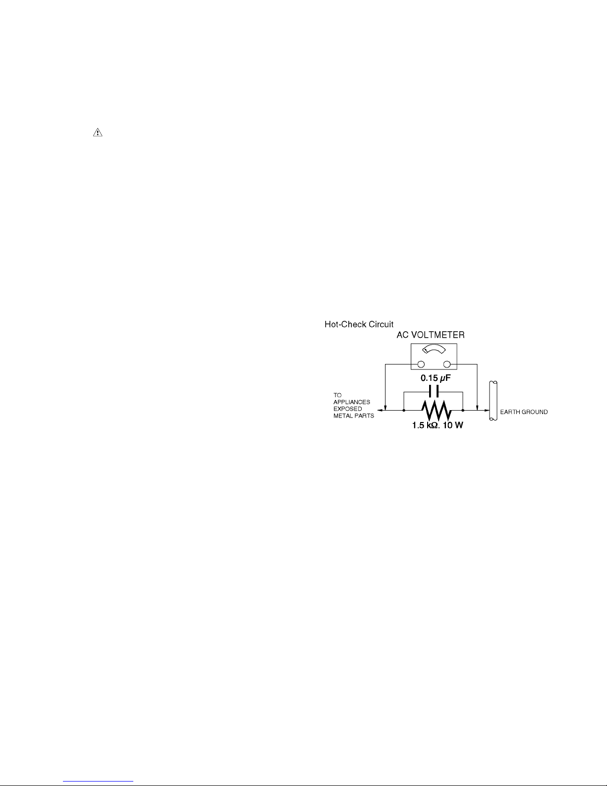
1.3. Leakage Current Hot Check
(See Figure 1.)
1. Plug the AC cord directly into the AC outlet. Do not use
an isolation transformer for this check.
2. Connect a 1.5 kΩ, 10 W resistor, in parallel with a 0.15 μF
capacitor, between each exposed metallic part on the set
and a good earth ground, as shown in Figure 1.
3. Use an AC voltmeter, with 1 kΩ/V or more sensitivity, to
measure the potential across the resistor.
4. Check each exposed metallic part, and measure the voltage at each point.
5. Reverse the AC plug in the AC outlet and repeat each of
the above measurements.
6. The potential at any point should not exceed 0.75 V RMS.
A leakage current tester (Simpson Model 229 or equivalent) may be used to make the hot checks, leakage current must not exceed 1/2 mA. In case a measurement is
outside of the limits specified, there is a possibility of a
shock hazard, and the equipment should be repaired and
rechecked before it is returned to the customer.
Figure. 1
4
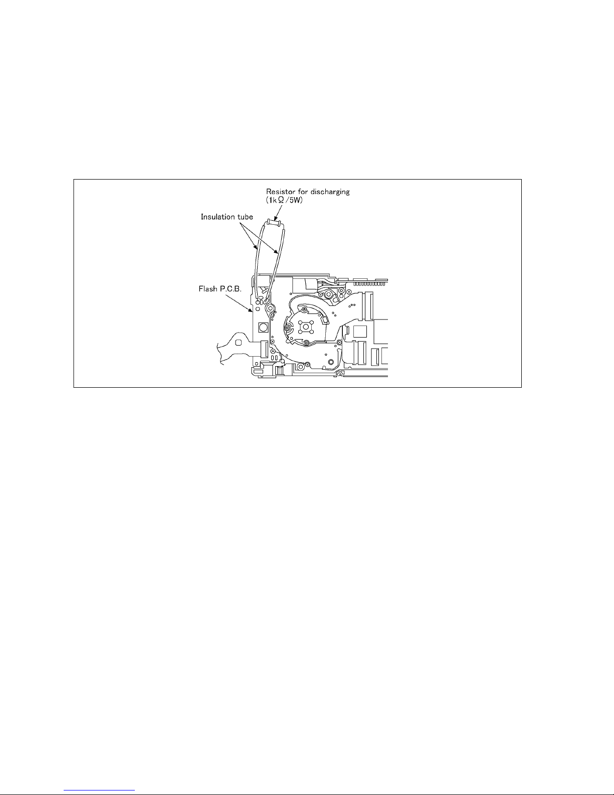
1.4. How to Discharge the E.Capacitor on Flash P.C.B.
CAUTION:
1. Be sure to discharge the E.capacitor on FLASH P.C.B..
2. Be careful of the high voltage circuit on FLASH P.C.B. when servicing.
[Discharging Procedure]
1. Refer to the disassemble procedure and remove the necessary parts/unit.
2. Install the insulation tube onto the lead part of resistor (ERG5SJ102:1kΩ /5W).
(An equivalent type of resistor may be used.)
3. Place a resistor between both terminals of E.capacitor on the FLASH P.C.B. for approx. 5 seconds.
4. After discharging, confirm that the E.capacitor voltage is lower than 10V by using a voltmeter.
Fig. F1
5
2Warning
2.1. Prevention of Electrostatic Discharge (ESD) to Electrostatically
Sensitive (ES) Devices
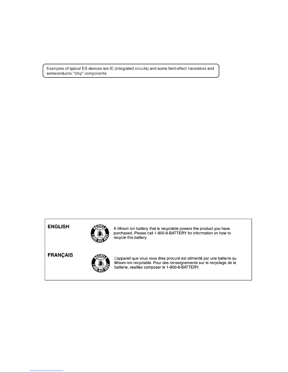
Some semiconductor (solid state) devices can be damaged easily by static electricity. Such components commonly are called Electrostatically Sensitive (ES) Devices.
The following techniques should be used to help reduce the incidence of component damage caused by electrostatic discharge
(ESD).
1. Immediately before handling any semiconductor component or semiconductor-equipped assembly, drain off any ESD on your
body by touching a known earth ground. Alternatively, obtain and wear a commercially available discharging ESD wrist strap,
which should be removed for potential shock reasons prior to applying power to the unit under test.
2. After removing an electrical assembly equipped with ES devices, place the assembly on a conductive surface such as aluminum foil, to prevent electrostatic charge buildup or exposure of the assembly.
3. Use only a grounded-tip soldering iron to solder or unsolder ES devices.
4. Use only an antistatic solder removal device. Some solder removal devices not classified as "antistatic (ESD protected)" can
generate electrical charge sufficient to damage ES devices.
5. Do not use freon-propelled chemicals. These can generate electrical charges sufficient to damage ES devices.
6. Do not remove a replacement ES device from its protective package until immediately before you are ready to install it. (Most
replacement ES devices are packaged with leads electrically shorted together by conductive foam, aluminum foil or comparable conductive material).
7. Immediately before removing the protective material from the leads of a replacement ES device, touch the protective material
to the chassis or circuit assembly into which the device will be installed.
CAUTION :
Be sure no power is applied to the chassis or circuit, and observe all other safety precautions.
8. Minimize bodily motions when handling unpackaged replacement ES devices. (Otherwise harmless motion such as the
brushing together of your clothes fabric or the lifting of your foot from a carpeted floor can generate static electricity (ESD) sufficient to damage an ES device).
2.2. How to Recycle the Lithium Ion Battery (U.S. Only)
6
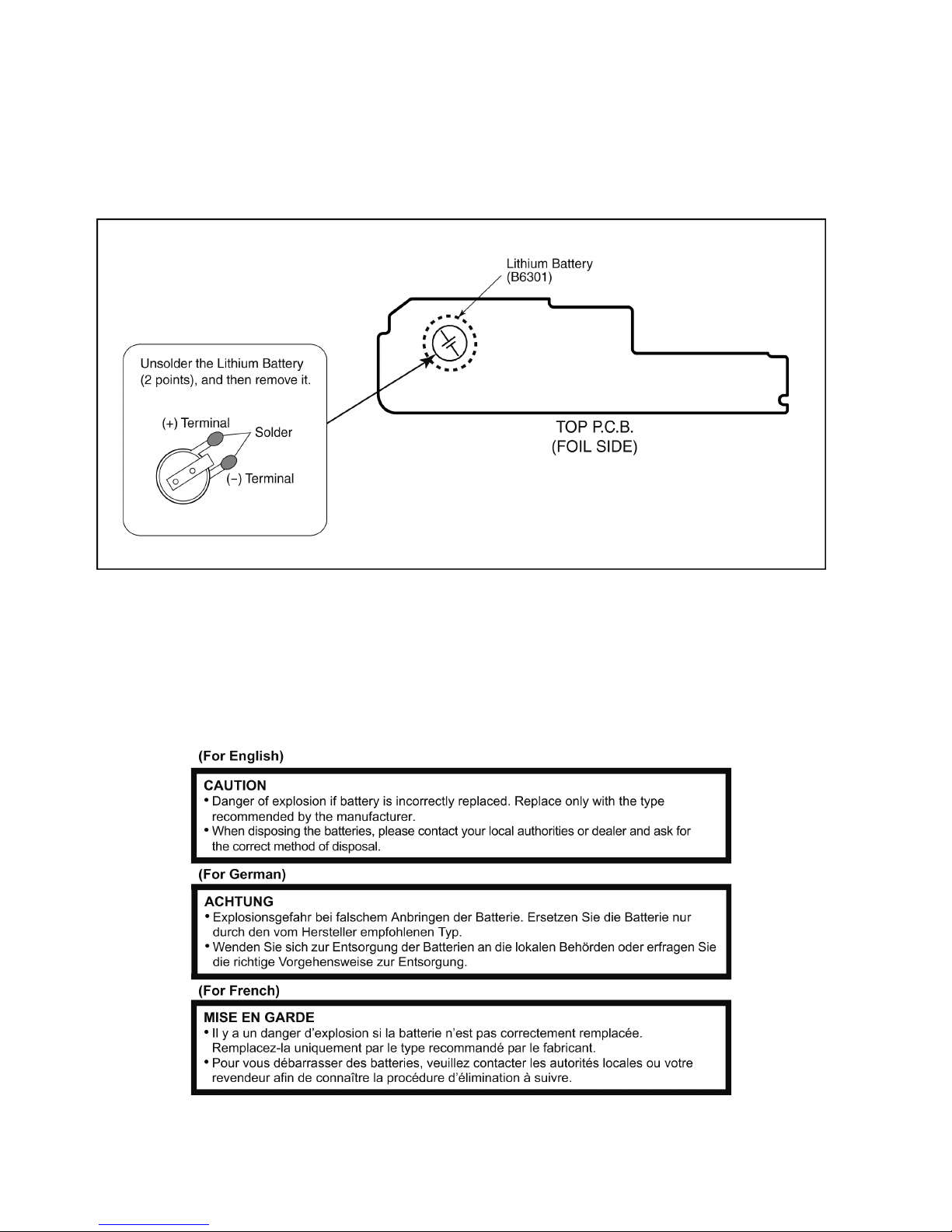
2.3. How to Replace the Lithium Battery
2.3.1. Replacement Procedure
1. Remove the TOP P.C.B.. (Refer to Disassembly Procedures.)
2. Unsolder the each soldering point of electric lead terminal for Lithium battery (Ref. No. “B6301” at foil side of TOP P.C.B.) and
remove the Lithium battery together with electric lead terminal. Then replace it into new one.
NOTE:
The Type No. ML421 includes electric lead terminals.
NOTE:
This Lithium battery is a critical component.
(Type No.: ML421 Manufactured by Energy Company, Panasonic Corporation.)
It must never be subjected to excessive heat or discharge.
It must therefore only be fitted in requirement designed specifically for its use.
Replacement batteries must be of same type and manufacture.
They must be fitted in the same manner and location as the original battery, with the correct polarity contacts observed.
Do not attempt to re-charge the old battery or re-use it for any other purpose.
It should be disposed of in waste products destined for burial rather than incineration.
NOTE:
Above caution is applicable for a battery pack which is for DMC-FH8/FS45 series, as well.
7
3 Service Navigation
3.1. Introduction
This service manual contains technical information, which allow service personnel’s to understand and service this model.
Please place orders using the parts list and not the drawing reference numbers.
If the circuit is changed or modified, the information will be followed by service manual to be controlled with original service manual.
3.2. Important Notice
3.2.1. CCD UNIT:
• The image sensor (CCD) unit which are connected to the lens unit with 3 screws.
These screws are adjusted for the Optical tilt.
During servicing, if one of CCD fixing screws are loosened, the Optical tilt adjustment must be performed.
About the Optical tilt adjustment, refer to the "9.3.2 Adjustment Specifications" for details.
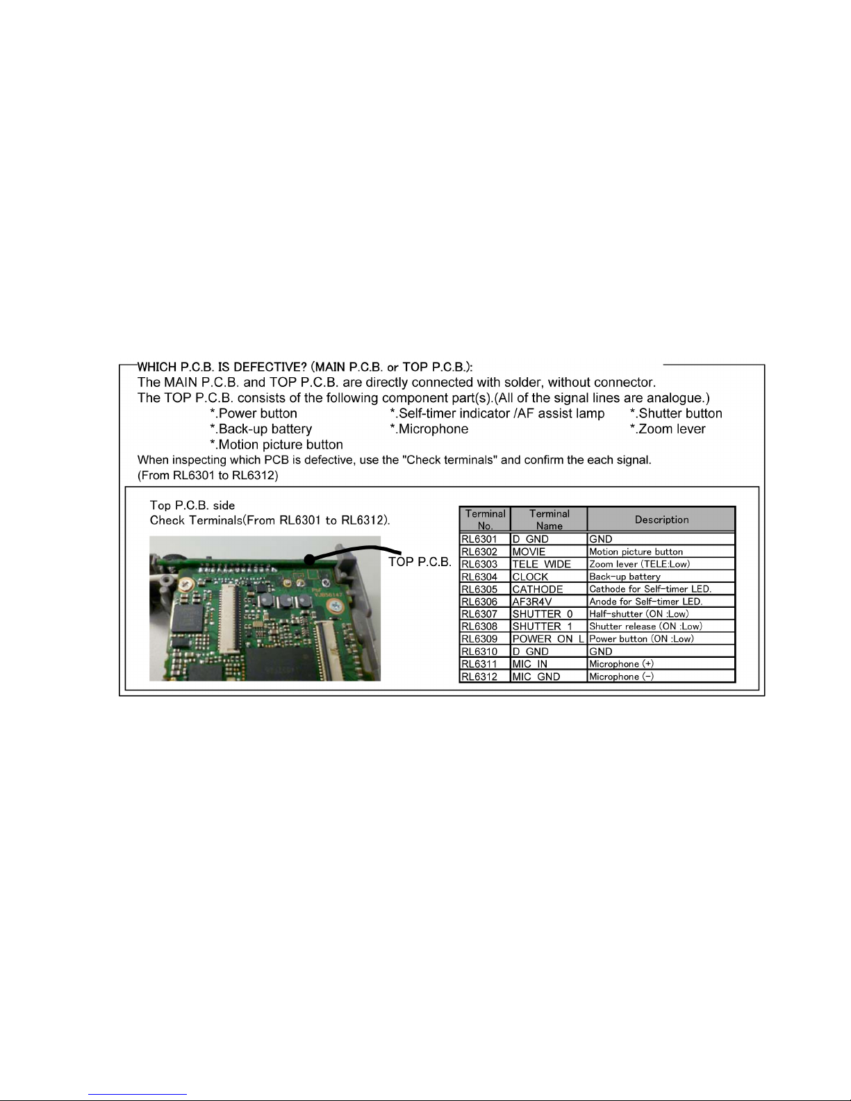
3.2.2. MAIN P.C.B.:
• The MAIN P.C.B. is handled as the smallest replacement part for this unit.
Therefore if any component on the MAIN P.C.B. is/are defective, replace whole MAIN P.C.B. as a unit.
8
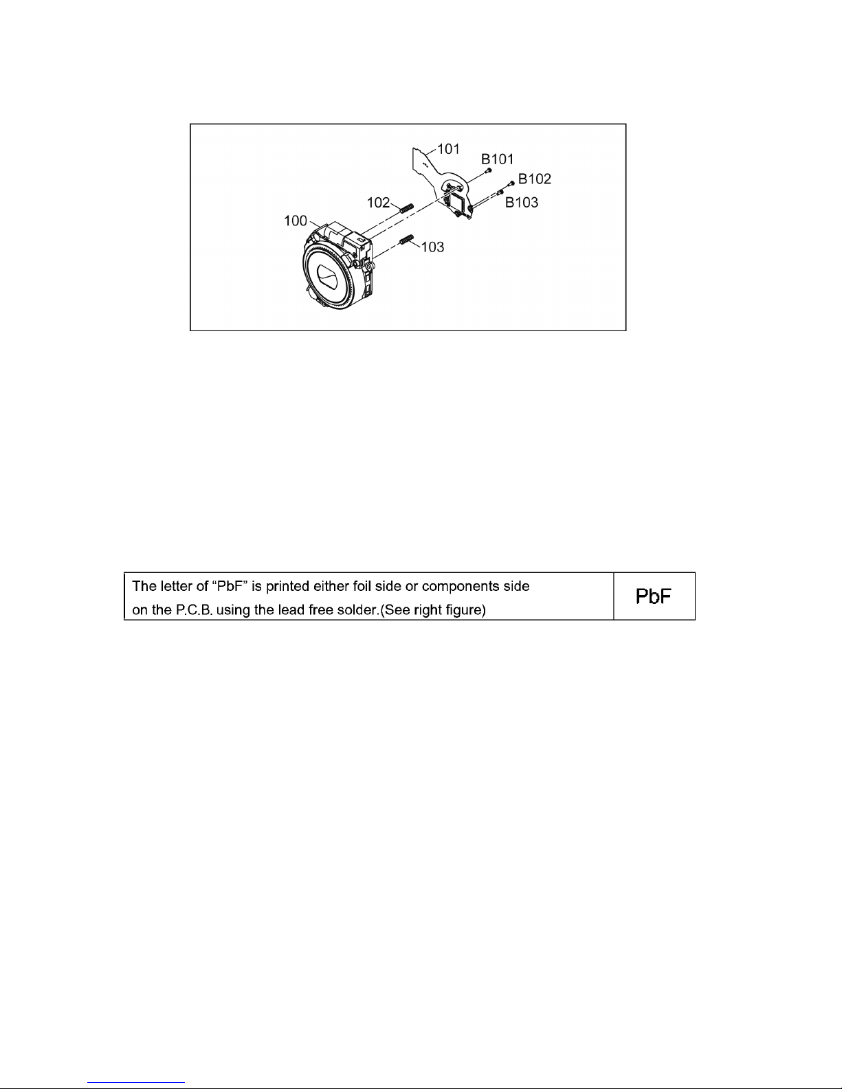
3.2.3. LENS UNIT:
The minimum replacement part size of the Lens part is as shown below.
When servicing, replace the following numbered replacement part size as the smallest size.
3.2.4. About Flexible Cable and Connector
Do not touch carelessly so that the foreign body should not adhere to the terminal part of flexible cable and connector.
Wipe off with a clean cloth and the cotton bud, etc. when the terminal part is dirty.
3.3. General Description About Lead Free Solder (PbF)
The lead free solder has been used in the mounting process of all electrical components on the printed circuit boards used for this
equipment in considering the globally environmental conservation.
The normal solder is the alloy of tin (Sn) and lead (Pb). On the other hand, the lead free solder is the alloy mainly consists of tin
(Sn), silver (Ag) and Copper (Cu), and the melting point of the lead free solder is higher approx.30°C (86°F) more than that of the
normal solder.
Distinction of P.C.B. Lead Free Solder being used
Service caution for repair work using Lead Free Solder (PbF)
• The lead free solder has to be used when repairing the equipment for which the lead free solder is used.
(Definition: The letter of “PbF” is printed on the P.C.B. using the lead free solder.)
• To put lead free solder, it should be well molten and mixed with the original lead free solder.
• Remove the remaining lead free solder on the P.C.B. cleanly for soldering of the new IC.
• Since the melting point of the lead free solder is higher than that of the normal lead solder, it takes the longer time to melt the
lead free solder.
• Use the soldering iron (more than 70W) equipped with the temperature control after setting the temperature at 350±30°C
(662±86°F).
Recommended Lead Free Solder (Service Parts Route.)
• The following 3 types of lead free solder are available through the service parts route.
RFKZ03D01KS-----------(0.3mm 100g Reel)
RFKZ06D01KS-----------(0.6mm 100g Reel)
RFKZ10D01KS-----------(1.0mm 100g Reel)
Note
* Ingredient: tin (Sn) 96.5%, silver (Ag) 3.0%, Copper (Cu) 0.5%, Cobalt (Co) / Germanium (Ge) 0.1 to 0.3%
9
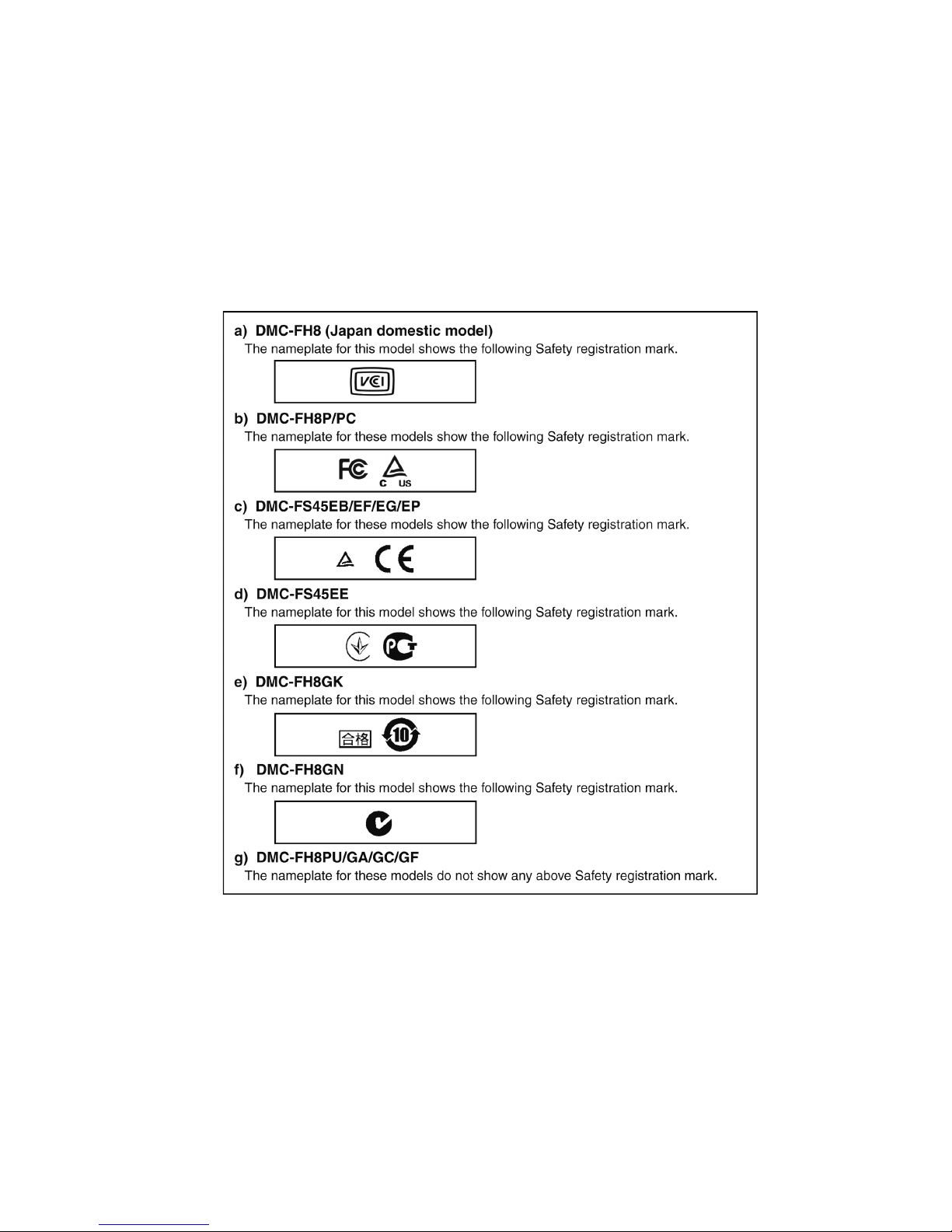
3.4. How to Define the Model Suffix (NTSC or PAL model)
There are seven kinds of DMC-FH8 and DMC-FS45, regardless of the colours.
• a) DMC-FH8 (Japan domestic model)
• b) DMC-FH8P/PC
• c) DMC-FS45EB/EF/EG/EP
• d) DMC-FS45EE
• e) DMC-FH8GK
• f) DMC-FH8GN
• g) DMC-FH8PU/GA/GC/GF
What is the difference is that the “INITIAL SETTINGS” data which is stored in Flash-ROM mounted on MAIN P.C.B..
3.4.1. Defining methods:
To define the model suffix to be serviced, refer to the nameplate which is putted on the bottom side of the Unit.
NOTE:
After replacing the MAIN P.C.B., be sure to achieve adjustment.
The service software is available at “TSN Website”. To download, click on “Support Information from NWBG/VDBG-AVC”.
10
3.4.2. INITIAL SETTINGS:
After replacing the MAIN P.C.B., make sure to perform the initial settings after achieving the adjustment by ordering the following
procedure in accordance with model suffix of the unit.
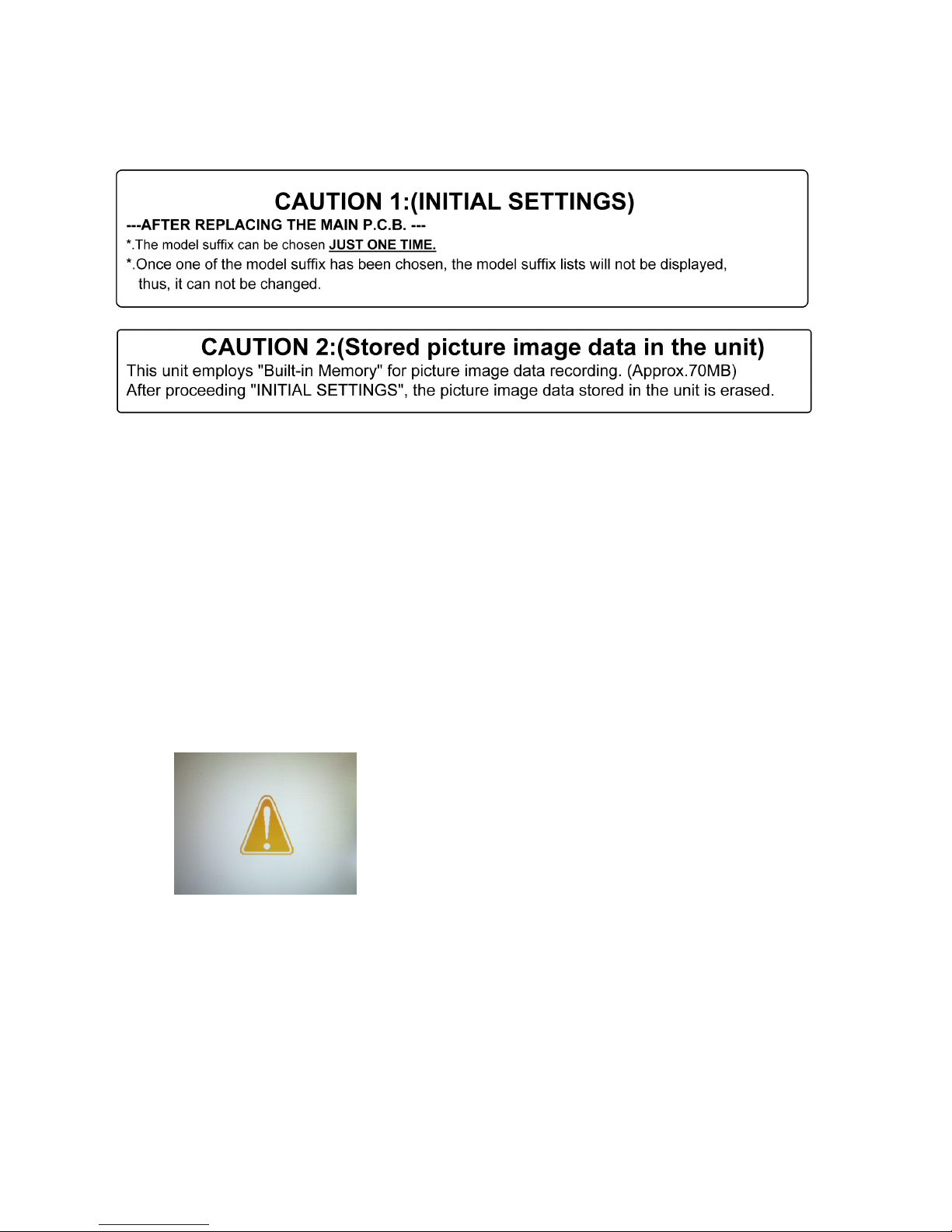
1. IMPORTANT NOTICE:
Before proceeding Initial settings, make sure to read the following CAUTIONS.
2. PROCEDURES:
• Precautions: Read the above "CAUTION 1" and "CAUTION 2", carefully.
• Preparation:
- Attach the Battery or AC Adaptor with a DC coupler to the unit.
(Since this unit has built-in memory, it can be performed without inserting SD memory card.)
1. Set the REC/PLAY switch to “[ REC ] (Camera mark)”, and then turn the Power on.
2. Press the [ MODE ] button, and select the [ NORMAL PICTURE ] mode by Cursor buttons, then press the [ MENU/SET ]
button.
3. Turn the Power off.
(If the unit is other than [ NORMAL PICTURE ] mode, it does not display the initial settings menu.)
• Step 1. The temporary cancellation of “INITIAL SETTINGS”:
Set the REC/PLAY switch to “[ REC ] (Camera mark)”.
While pressing “[ UP ] of Cursor button” and [ MOTION PICTURE ] button simultaneously, turn the Power on.
• Step 2. The cancellation of “INITIAL SETTINGS”:
Set the REC/PLAY switch to “[ PLAY ]”.
Press “[ UP ] of Cursor button” and [ MOTION PICTURE ] button simultaneously, turn the Power off.
The LCD displays the " ! " mark before the unit powers down.
• Step 3. Turn the Power on:
Set the REC/PLAY switch to “[ REC ] (Camera mark)”, and then turn the Power on.
• Step 4. Display the INITIAL SETTING:
While pressing [ MENU/SET ] button and “[ RIGHT ] of Cursor button” simultaneously, turn the Power off.
The “INITIAL SETTINGS” menu is displayed.
There are two kinds of “INITIAL SETTINGS” menu form as follows:
11
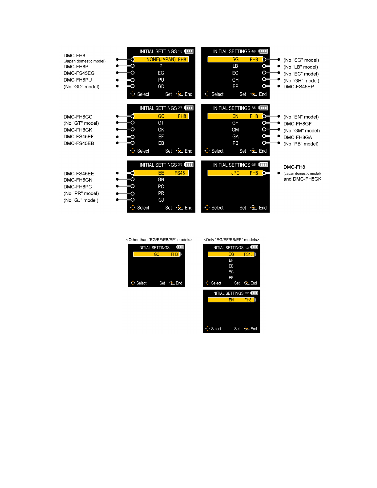
[CASE 1. After replacing MAIN P.C.B.]
When MAIN P.C.B. has just been replaced, all of the model suffix is displayed as follows. (Five pages in total)
[CASE 2. Other than “After replacing MAIN P.C.B.”]
• Step 5. Choose the model suffix in “INITIAL SETTINGS”: (Refer to “CAUTION 1”)
[Caution: After replacing MAIN P.C.B.]
The model suffix can been chosen, JUST ONE TIME.
Once one of the model suffix have been chosen, the model suffix lists will not be displayed, thus, it can not be changed.
Therefore, select the area carefully.
Select the area with pressing “[ UP ] / [ DOWN ] of Cursor buttons”.
12
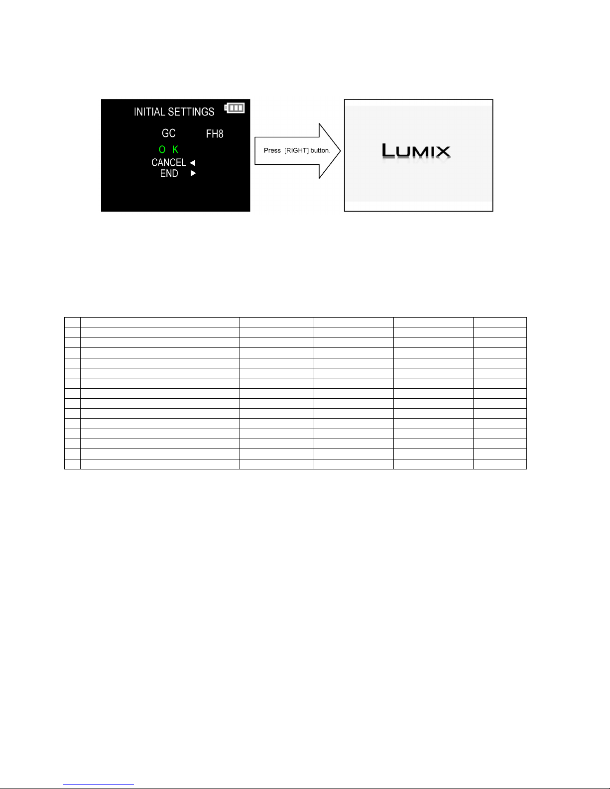
• Step 6. Set the model suffix in “INITIAL SETTINGS”:
Press the “[ RIGHT ] of Cursor buttons”.
The only set area is displayed, and then press the “[ RIGHT ] of Cursor buttons” after confirmation.
(The unit is powered off automatically.)
• Step 7. CONFIRMATION:
Confirm the display of “PLEASE SET THE CLOCK” in concerned language when the unit is turned on again.
When the unit is connected to PC with USB cable, it is detected as removable media.
(When the “GK” model suffix is selected, the display shows “PLEASE SET THE CLOCK” in Chinese.)
1) As for your reference, major default setting condition is as shown in the following table.
• Default setting (After “INITIAL SETTINGS”)
MODEL VIDEO OUTPUT LANGUAGE DATE REMARKS
a) DMC-FH8(Japan domestic model) NTSC Japanese Year/Month/Date
b) DMC-FH8P NTSC English Month/Date/Year
c) DMC-FH8PC NTSC English Month/Date/Year
d) DMC-FH8PU NTSC Spanish Month/Date/Year
e) DMC-FS45EG PAL English Date/Month/Year
f) DMC-FS45EP PAL English Date/Month/Year
g) DMC-FS45EF PAL French Date/Month/Year
h) DMC-FS45EB PAL English Date/Month/Year
i) DMC-FS45EE PAL Russian Date/Month/Year
j) DMC-FH8GC PAL English Date/Month/Year
k) DMC-FH8GF PAL English Date/Month/Year
l) DMC-FH8GA PAL English Date/Month/Year
m) DMC-FH8GK PAL Chinese (simplified) Year/Month/Date
n) DMC-FH8GN PAL English Date/Month/Year
13
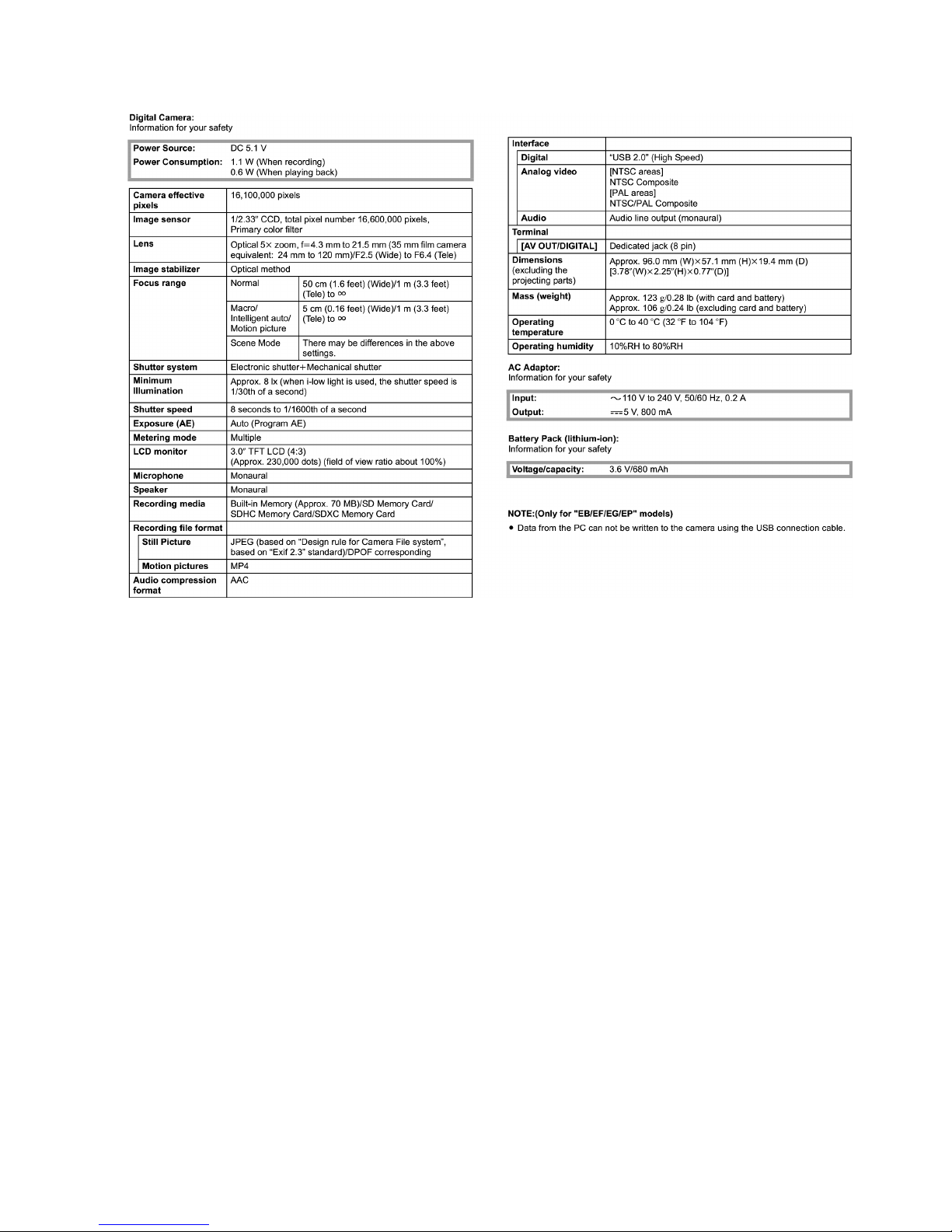
4 Specifications

14
5 Location of Controls and Components
1Flash
2 Lens
3 Self-timer indicator
AF Assist Lamp
4 LCD monitor
5 [MENU/SET] button
6 [DISP.] button
7 [Q.MENU] /[ ] (Delete/
Cancel) button
8 [MODE] button
9 REC/PLAY switch
10 Charging lamp
3 1 2
7
4
10
98
11
5
11 Cursor buttons
: /Exposure compensation
: /Macro Mode
AF Tracking
: /Self-timer
: /Flash setting
12 Strap eyelet
Be sure to attach the strap when using
the camera to ensure that you will not
drop it.
13 Lens barrel
14 [AV OUT/DIGITAL] socket
13
14
12
15 Speaker
Be careful not to cover the speaker with
your finger. Doing so may make sound
difficult to hear.
16 Camera ON/OFF switch
17 Zoom lever
18 Microphone
19 Shutter button
20 Motion picture button
21 Tripod receptacle
22 Card/Battery door
23 Release lever
21 22
15 23
16 17
18 19 20
6
15
Basic
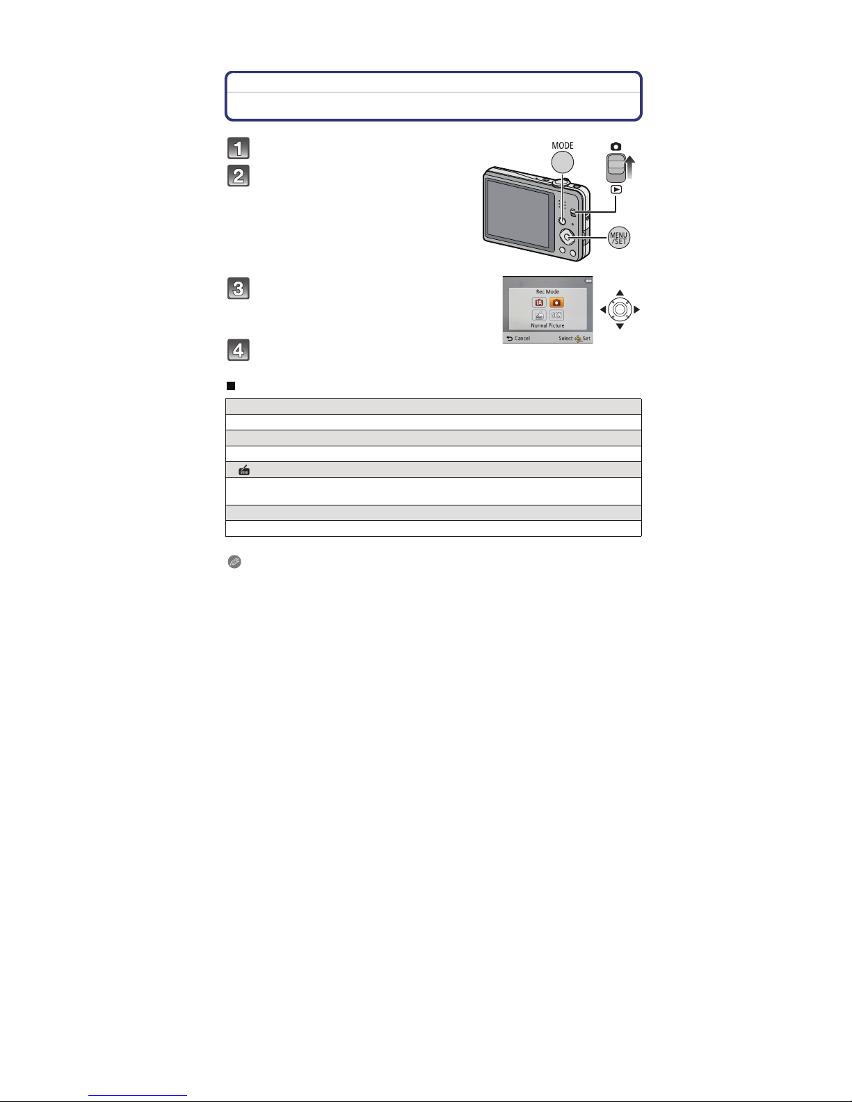
Selecting the Recording Mode
List of Recording Modes
Note
When the mode has been switched from Playback Mode to Recording Mode, the previously set
Recording Mode will be set.
Slide the REC/PLAY switch to [].
Press [MODE].
Press /// to select the Recording
Mode.
Press [MENU/SET].
}
Intelligent Auto Mode
The subjects are recorded using settings automatically selected by the camera.
Normal Picture Mode
The subjects are recorded using your own settings.
Miniature Effect Mode
This is an imaging effect which defocuses the surroundings to make it look like a
diorama. (also known as Tilt Shift Focus)
±
Scene Mode
This allows you to take pictures that match the scene being recorded.
16
6 Service Mode
6.1. Error Code Memory Function
1. General description
This unit is equipped with history of error code memory function, and can be memorized 16 error codes in sequence from the
latest. When the error is occurred more than 16, the oldest error is overwritten in sequence.
The error code is not memorized when the power supply is shut down forcibly (i.e.,when the unit is powered on by the battery,
the battery is pulled out) The error code is memorized to FLASH-ROM when the unit has just before powered off.
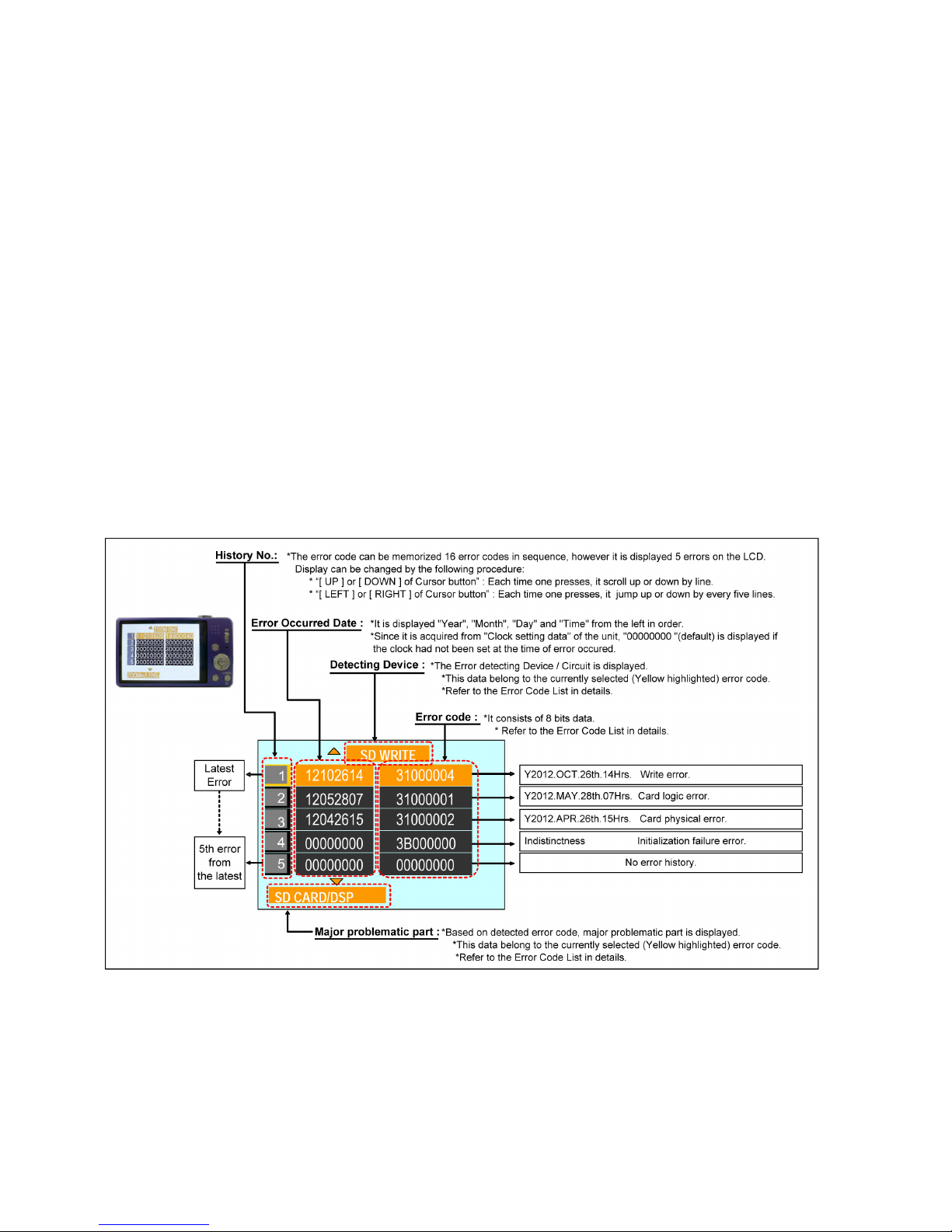
2. How to display
The error code can be displayed by ordering the following procedure:
• Preparation
- Attach the Battery or AC Adaptor with a DC coupler to the unit.
(Since this unit has built-in memory, it can be performed without inserting SD memory card.)
1. Set the REC/PLAY switch to “[ REC ] (Camera mark)”, and then turn the Power on.
2. Press the [ MODE ] button, and select the [ NORMAL PICTURE ] mode by Cursor buttons, then press the [ MENU/SET ]
button.
3. Turn the Power off.
(If the unit is other than [ NORMAL PICTURE ] mode, it does not display the initial settings menu.)
• Step 1. The temporary cancellation of "INITIAL SETTINGS":
Set the REC/PLAY switch to “[ REC ] (Camera mark)”.
While pressing “[ UP ] of Cursor button” and [ MOTION PICTURE ] button simultaneously, turn the Power on.
• Step 2. Execute the error code display mode:
Press the "[ LEFT ] of Cursor button" , [ MENU/SET ] button and [ MOTION PICTURE ] button simultaneously.
The display is changed as shown below when the above buttons are pressed simultaneously.
Normal display → Error code display → Operation history display →Normal display →.....
Example of Error Code Display
17
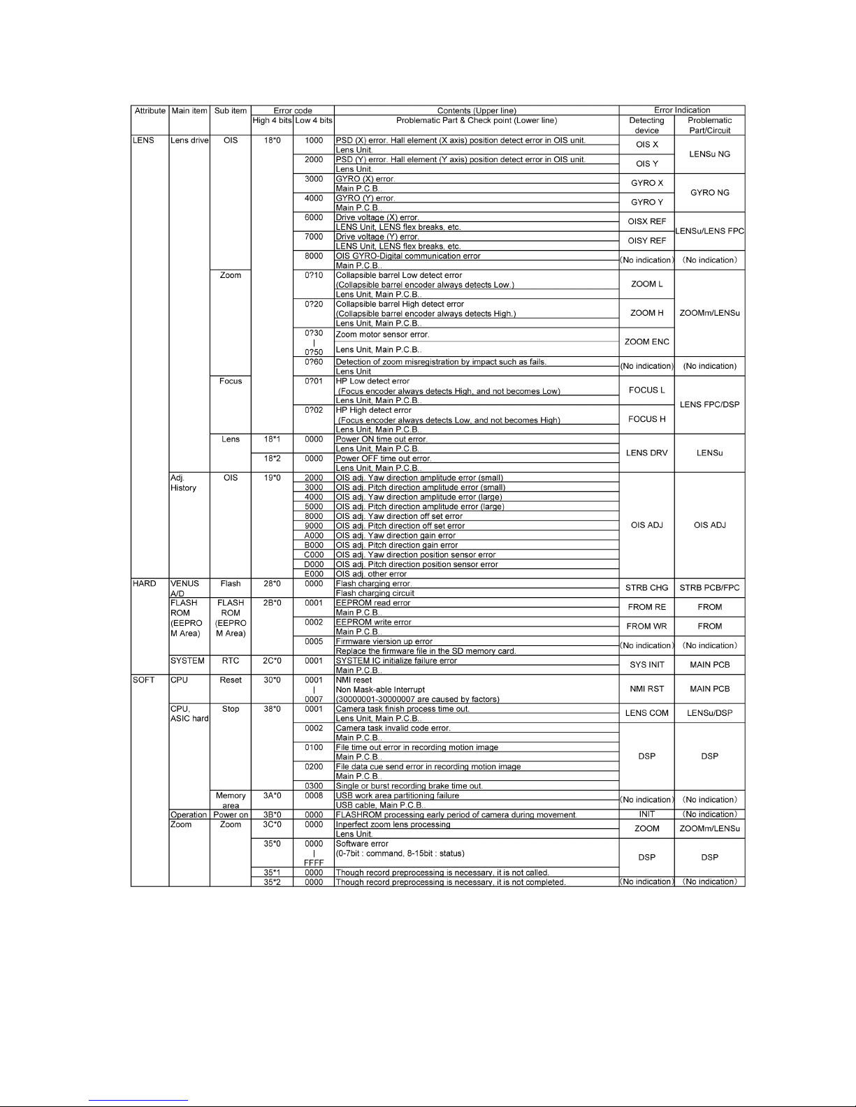
• 3. Error Code List
The error code consists of 8 bits data and it shows the following information.

18
Important notice about "Error Code List"
1) About "*" indication:
The third digit from the left is different as follows.
- In case of 0 (example: 180
01000)
When the third digit from the left shows "0", this error occurred under the condition of INITIAL SETTINGS has been
completed.
It means that this error is occurred basically at user side.
- In case of 8 (example: 188
01000)
When the third digit from the left shows "8", this error occurred under the condition of INITIAL SETTINGS has been
released.
(Example; Factory assembling-line before unit shipment, Service mode etc.)
It means that this error is occurred at service side.
2) About "?" indication: ("18*0 0?01" to "18*0 0?60"):
The third digit from the right shows one of the hexadecimal ("0" to "F") character.
• 4. How to exit from Error Code display mode:
Simply, turn the power off. (Since Error code display mode is executed under the condition of temporary cancellation of "INITIAL SETTINGS", it wake up with normal condition when turn off the power.)
NOTE:
The error code can not be initialized.
19
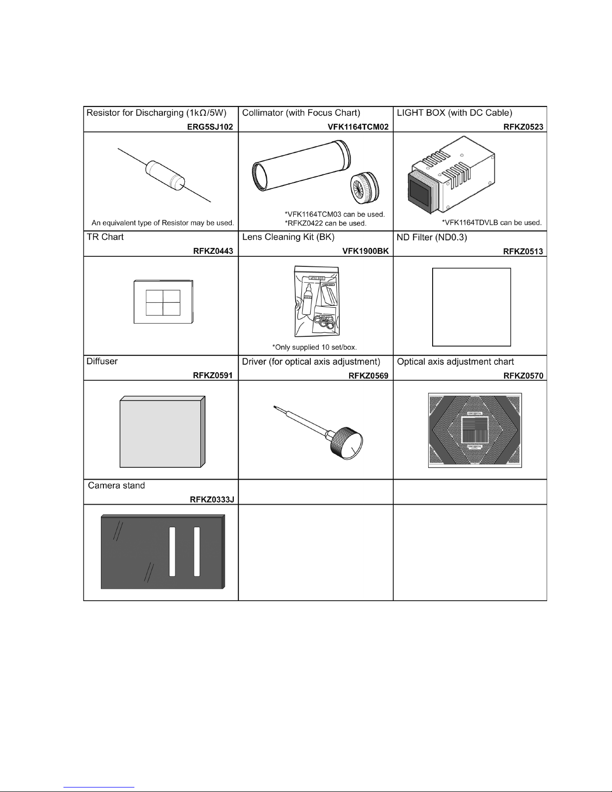
7 Service Fixture & Tools
7.1. Service Fixture and Tools
The following Service Fixture and tools are used for checking and servicing this unit.
7.2. When Replacing the Main P.C.B.
After replacing the MAIN P.C.B., be sure to achieve adjustment.
The service software is available at “TSN Website”. To download, click on “Support Information from NWBG/VDBG-AVC”.
 Loading...