

Page 1

Digital Business System
Section 540
T1 Networking
Reference
Manual
Doc. No. 550X10001A
Revised April 2000
Page 2

The contents of this manual are subject to change without notice and do not constitute a
commitment on the part of Panasonic Telecommunication Systems Company (PTSC). Every
effort has been made to ensure the accuracy of this document. However, due to ongoing product
improvements and revisions, Panasonic cannot guarantee the accuracy of printed material after
the date of publication nor can it accept responsibility for errors or omissions. Panasonic will
update and revise this document as needed.
The software and hardware described in this document may be used or copied only in accordance
with the terms of the license pertaining to said software or hardware.
This document may be reproduced either electronically or in print as needed by certified dealers
and technicians of DBS products. However, the information contained in this document must not
be altered, copied, or changed in any way that misrepresents the installation, operation, or other
function or feature of the DBS product or Panasonic. Panasonic assumes no liability for any
alteration or misrepresentation of information contain herein.
Copyright 1996 by Panasonic Telecommunication Systems Company (PTSC)
Revised April 2000. All rights reserved.
Reference to third-party products is for information only and does not constitute an endorsement
or recommendation. Panasonic does not assume responsibility for the performance of third-party
products.
Page 3

Contents
Chapter 1. Introduction to DBS T1 Networking
Overview . . . . . . . . . . . . . . . . . . . . . . . . . . . . . . . . . . . . . . . . . . . . . . . . . . . . . . . . . . . . . . . . . . 7
Description of T1 Networking . . . . . . . . . . . . . . . . . . . . . . . . . . . . . . . . . . . . . . . . . . . . . . . 7
Pre-Installation Requirements . . . . . . . . . . . . . . . . . . . . . . . . . . . . . . . . . . . . . . . . . . . . . . . . . . 9
Ordering T1 Services . . . . . . . . . . . . . . . . . . . . . . . . . . . . . . . . . . . . . . . . . . . . . . . . . . . . . . 9
What You Must Purchase . . . . . . . . . . . . . . . . . . . . . . . . . . . . . . . . . . . . . . . . . . . . . . . . . 10
System Requirements . . . . . . . . . . . . . . . . . . . . . . . . . . . . . . . . . . . . . . . . . . . . . . . . . . . . 10
Maximums . . . . . . . . . . . . . . . . . . . . . . . . . . . . . . . . . . . . . . . . . . . . . . . . . . . . . . . . . . . . . 10
Chapter 2. System Planning
System Planning Forms and Guidelines . . . . . . . . . . . . . . . . . . . . . . . . . . . . . . . . . . . . . . . . . 13
About the Example . . . . . . . . . . . . . . . . . . . . . . . . . . . . . . . . . . . . . . . . . . . . . . . . . . . . . . 13
Basic Site Layout and Numbering Plan . . . . . . . . . . . . . . . . . . . . . . . . . . . . . . . . . . . . . . . 14
Network Trunk Configuration and Trunk Routing . . . . . . . . . . . . . . . . . . . . . . . . . . . . . . 15
Network Trunk Group Selection . . . . . . . . . . . . . . . . . . . . . . . . . . . . . . . . . . . . . . . . . . . . 21
Network Page Group Operation . . . . . . . . . . . . . . . . . . . . . . . . . . . . . . . . . . . . . . . . . . . . 23
Network Attendant Calling . . . . . . . . . . . . . . . . . . . . . . . . . . . . . . . . . . . . . . . . . . . . . . . . 29
Node Route Selection (NRS) . . . . . . . . . . . . . . . . . . . . . . . . . . . . . . . . . . . . . . . . . . . . . . . 29
Toll Restriction Service (TRS) Restrictions . . . . . . . . . . . . . . . . . . . . . . . . . . . . . . . . . . . 38
Forwarding Incoming CO Calls to Another DBS Node . . . . . . . . . . . . . . . . . . . . . . . . . . 54
SMDR Settings . . . . . . . . . . . . . . . . . . . . . . . . . . . . . . . . . . . . . . . . . . . . . . . . . . . . . . . . . 59
Chapter 3. Quick-Start Programming
Before You Begin . . . . . . . . . . . . . . . . . . . . . . . . . . . . . . . . . . . . . . . . . . . . . . . . . . . . . . . . . . 63
Hardware Setup . . . . . . . . . . . . . . . . . . . . . . . . . . . . . . . . . . . . . . . . . . . . . . . . . . . . . . . . . . . . 63
Programming Initial T1 Network Options . . . . . . . . . . . . . . . . . . . . . . . . . . . . . . . . . . . . . . . . 65
Chapter 4. Programming
Settings Modified for Networking . . . . . . . . . . . . . . . . . . . . . . . . . . . . . . . . . . . . . . . . . . . . . . 81
System Settings . . . . . . . . . . . . . . . . . . . . . . . . . . . . . . . . . . . . . . . . . . . . . . . . . . . . . . . . . 81
Trunk Settings . . . . . . . . . . . . . . . . . . . . . . . . . . . . . . . . . . . . . . . . . . . . . . . . . . . . . . . . . . 82
Extension Settings . . . . . . . . . . . . . . . . . . . . . . . . . . . . . . . . . . . . . . . . . . . . . . . . . . . . . . . 82
Other Changes . . . . . . . . . . . . . . . . . . . . . . . . . . . . . . . . . . . . . . . . . . . . . . . . . . . . . . . . . . 83
T1 Settings Added for Networking . . . . . . . . . . . . . . . . . . . . . . . . . . . . . . . . . . . . . . . . . . . . . 84
DBS-2.3/9.2-540 T1 Networking-Revised April 2000 Page 3
Page 4

Chapter 5. Network Feature Operation
Call Forwarding to Extensions on Another Node . . . . . . . . . . . . . . . . . . . . . . . . . . . . . . . . . 103
Extension to Network Extension Calling . . . . . . . . . . . . . . . . . . . . . . . . . . . . . . . . . . . . . . . 105
Forwarding CO Calls to Network Extensions . . . . . . . . . . . . . . . . . . . . . . . . . . . . . . . . . . . . 107
Network Attendant Call . . . . . . . . . . . . . . . . . . . . . . . . . . . . . . . . . . . . . . . . . . . . . . . . . . . . . 108
Network Call Transfer . . . . . . . . . . . . . . . . . . . . . . . . . . . . . . . . . . . . . . . . . . . . . . . . . . . . . . 111
Blind Transfer . . . . . . . . . . . . . . . . . . . . . . . . . . . . . . . . . . . . . . . . . . . . . . . . . . . . . . . . . 111
Screened Transfer . . . . . . . . . . . . . . . . . . . . . . . . . . . . . . . . . . . . . . . . . . . . . . . . . . . . . . 113
Network Conference Calls . . . . . . . . . . . . . . . . . . . . . . . . . . . . . . . . . . . . . . . . . . . . . . . . . . . 116
Network DISA Calling . . . . . . . . . . . . . . . . . . . . . . . . . . . . . . . . . . . . . . . . . . . . . . . . . . . . . 119
Network Paging . . . . . . . . . . . . . . . . . . . . . . . . . . . . . . . . . . . . . . . . . . . . . . . . . . . . . . . . . . . 122
Node Route Selection (NRS) . . . . . . . . . . . . . . . . . . . . . . . . . . . . . . . . . . . . . . . . . . . . . . . . . 124
Remote Network DBS CO Access . . . . . . . . . . . . . . . . . . . . . . . . . . . . . . . . . . . . . . . . . . . . 125
SMDR . . . . . . . . . . . . . . . . . . . . . . . . . . . . . . . . . . . . . . . . . . . . . . . . . . . . . . . . . . . . . . . . . . 126
Chapter 6. Sync Source Examples
T1 Network - Two System Connections . . . . . . . . . . . . . . . . . . . . . . . . . . . . . . . . . . . . . . . . 129
Local Connections - Not Through CO . . . . . . . . . . . . . . . . . . . . . . . . . . . . . . . . . . . . . . . 129
Remote Connection - Through CO . . . . . . . . . . . . . . . . . . . . . . . . . . . . . . . . . . . . . . . . . 130
T1 Network - Three System Connections . . . . . . . . . . . . . . . . . . . . . . . . . . . . . . . . . . . . . . . 132
Local Connection - Not Through CO . . . . . . . . . . . . . . . . . . . . . . . . . . . . . . . . . . . . . . . 132
Remote Connections - Through CO . . . . . . . . . . . . . . . . . . . . . . . . . . . . . . . . . . . . . . . . 135
T1 Network - Four System Connection . . . . . . . . . . . . . . . . . . . . . . . . . . . . . . . . . . . . . . . . . 136
Local Connection - Not Through CO . . . . . . . . . . . . . . . . . . . . . . . . . . . . . . . . . . . . . . . 136
Remote Connection - Through CO . . . . . . . . . . . . . . . . . . . . . . . . . . . . . . . . . . . . . . . . . 138
DBS Network Telephone User Guide
Calling a Network Extension . . . . . . . . . . . . . . . . . . . . . . . . . . . . . . . . . . . . . . . . . . . . . . . . . 141
Calling the Attendant . . . . . . . . . . . . . . . . . . . . . . . . . . . . . . . . . . . . . . . . . . . . . . . . . . . . . . . 141
Call Forwarding to Extensions on Another Node . . . . . . . . . . . . . . . . . . . . . . . . . . . . . . . . . 141
Network Paging . . . . . . . . . . . . . . . . . . . . . . . . . . . . . . . . . . . . . . . . . . . . . . . . . . . . . . . . . . . 141
Transferring Calls to the Network . . . . . . . . . . . . . . . . . . . . . . . . . . . . . . . . . . . . . . . . . . . . . 142
Blind Transfer . . . . . . . . . . . . . . . . . . . . . . . . . . . . . . . . . . . . . . . . . . . . . . . . . . . . . . . . . 142
Screened Transfer . . . . . . . . . . . . . . . . . . . . . . . . . . . . . . . . . . . . . . . . . . . . . . . . . . . . . . 142
Conferencing Calls . . . . . . . . . . . . . . . . . . . . . . . . . . . . . . . . . . . . . . . . . . . . . . . . . . . . . . . . 142
Accessing Outside Lines on Another Node . . . . . . . . . . . . . . . . . . . . . . . . . . . . . . . . . . . . . . 142
Page 4 T1 Networking - Revised April 2000 DBS-2.3/9.2-540
Page 5

Chapter 1. Introduction to DBS T1
Networking
This chapter provides an overview of DBS T1 Networking.
The following table summarizes the topics contained in this chapter.
Topic Page
Overview 7
Description of T1 Networking 7
Pre-Installation Requirements 9
Ordering T1 Services 9
What You Must Purchase 10
System Requirements 10
Maximums 10
DBS-2.3/9.2-540 T1 Networking-Revised April 2000 Page 5
Page 6

Page 6 T1 Networking - Revised April 2000 DBS-2.3/9.2-540
Page 7

Introduction to DBS T1 Networking Overview
Overview
Description of T1 Networking
Two to four DBS systems may be interconnected using T1 connections to
create a DBS telephone network. The DBS systems may be located in the
same building, separate buildings, across the city or across the country.
DBS T1 Networking provides the following features:
• Network Extension to Extension Calling
• Call forwarding to Network Extensions
• Paging to Network DBS
• Network Route Selection
• Remote DBS CO Access
• SMDR Network Support
• Common Network Attendant Calling (calls that revert to the attendant will
go to the local attendant)
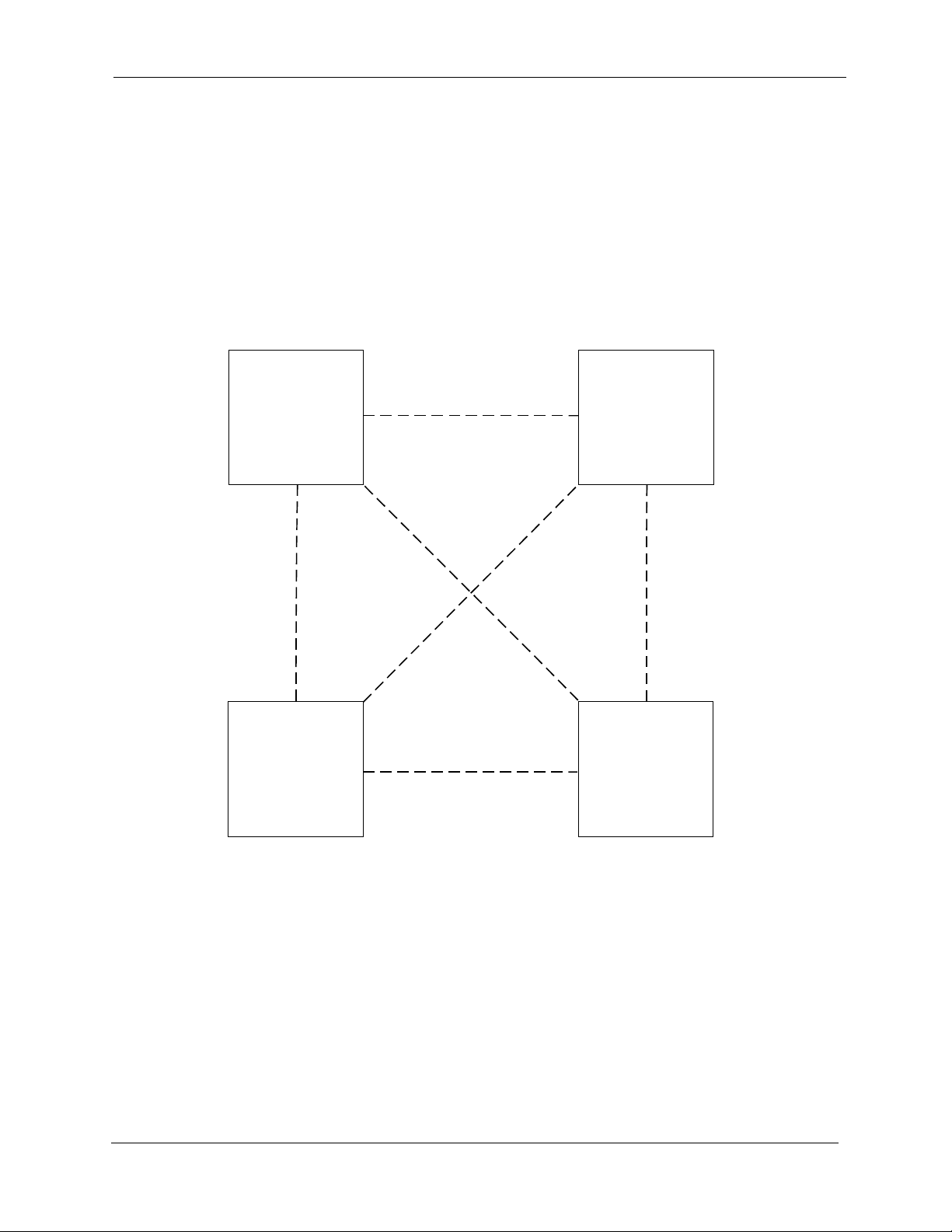
The T1 Network consists of two to four DBS systems that use 4-digit
numbering. The first digit (1 to 4) specifies the network DBS location (or
node) to receive the call. The remaining digits follow the conventional threedigit DBS numbering plan. For instance, dialing 2105 selects extension 105
on Network DBS node 2.
Figure 1-1. DBS Network Numbering Plan
DBS 1
1XXX
DBS 2
2XXX
DBS 4
4XXX
DBS-10-540 T1 Networking - Issued 9/6/96 Page 7
DBS 3
3XXX
Page 8

Overview
Introduction to DBS T1 Networking
Page 8 T1 Networking - Revised April 2000 DBS-2.3/9.2-540
Page 9

Introduction to DBS T1 Networking Pre-Installation Requirements
Pre-Installation Requirements
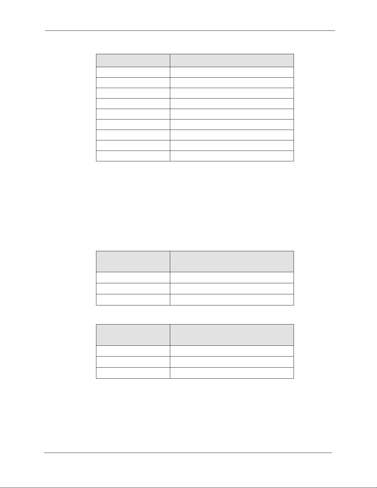
Use the following guidelines to prepare your site for T1 installation.
Ordering T1 Servi c es
The following guidelines describe T1options that must be ordered from your
central office or interexchange carrier (if used). These guidelines are designed
to cover almost all T1 installations. However, special requirements should be
discussed with your provider.
Table 1-1. Guidelines for ordering T1 services
Item to be Ordered Options
Line Type E&M with wink start for both incoming and outgoing calls.
Trunk Signaling Wink start
Signaling Code DS-1
Line Code AMI
Framing Format D4 (Superframe) or ESF (Extended Superframe). D4 is used in
most cases.
Signaling Method In-band
Tones Coordinate with T1 Service Provider.
Note: If the CO does not provide dial tone, program the DBS to
generate its own dial tone.
DBS-10-540 T1 Networking - Issued 9/6/96 Page 9
Page 10

Pre-Installation Requirements
What You Must Purchase
Each DBS system in the network must have the appropriate T1 equipment as
described in the DBS T1 Reference Manual and the DBS Installation Manual.
Please refer to these manuals for a description of what must be purchased.
Note: The DBS T1 Trunk Card (VB-43561) must contain COP Version 2.0 or
later.
System Requirements
• A CPC-EX is required in every networked DBS system.
• Each DBS must contain one or two T1 interfaces with at least a portion of
the trunks dedicated to network traffic.
• Some DBS configurations limit the number of T1 interfaces that may be
used. See Section 500 - T1 Supplement for more information.
Introduction to DBS T1 Networking
Maximums
• Depending on the DBS cabinet configuration, each DBS in the network
may have up to 48 T1 trunks dedicated to T1 Networking.
Note: Any T1 trunks not dedicated to T1 networking may be used for
outside CO trunks. However each trunk used in the network diminishes the
number of T1 trunks available for outside CO connections. Trunk ports not
used by T1 (either with network or non-network) are available for CO
trunks.
• Up to four DBS systems may be included in the DBS Network.
Page 10 T1 Networking - Revised April 2000 DBS-2.3/9.2-540
Page 11

Chapter 2. System Planning
This section provides system planning guidelines and procedures required for
a DBS T1 Network and provides an example DBS Network Setup. Once this
planning is performed, see Chapter 3 - “Installation and Quick Start
Programming” and Chapter 4 - “Programming Reference” for programming
instructions.
This chapter covers the following topics.
Topic Page
System Planning Forms and Guidelines 13
About the Example 13
Network Trunk Configuration and Trunk Routing 15
Network Trunk Group Selection 21
Network Page Group Operation 23
Network Attendant Calling 29
Node Route Selection (NRS) 29
Toll Restriction Service (TRS) Restrictions 38
Forwarding Incoming CO Calls to Another DBS Node 54
SMDR Settings 59
DBS-2.3/9.2-540 T1 Networking-Revised April 2000 Page 11
Page 12

Page 12 T1 Networking - Revised April 2000 DBS-2.3/9.2-540
Page 13

System Planning System Planning Forms and Guidelines
System Planning Forms and Guidelines
Note: This manual assumes that the T1 card has been successfully installed
in the DBS Cabinets. See Section 500 - T1 Reference Manual for T1
Installation Instructions.
About the Example
Most forms in the following pages are followed by an example. For these
example forms, it is determined there are four locations across the country to
be networked together as follows:
• The sites are named after their locations -- Northwest (area code 202),
Northeast (area code 303), Southeast (area code 404) and Southwest (area
code 505)
• Each site contains dual-cabinet DBS 96 systems and contain two T1
interfaces
• The calling traffic between DBS systems is balanced (an even amount of
traffic is expected between systems). The maximum number of
simultaneous calls between any two DBS systems is expected to be 8 calls
or less.
• Every station is allowed to page anywhere on the network
• A network attendant is located at DBS 1
• Node Route Selection (routing calls to another node for outbound
processing) is to be used for calls in a remote DBS’ area code
• TRS is to be used to restrict long distance calls originating from a distant
DBS for some extensions.
DBS-2.3/9.2-540 T1 Networking - Revised April 2000 Page 13
Page 14

System Planning Forms and Guidelines
Basic Site Layout and Nu mbering Plan
Determine the DBS systems to be included in the DBS network and assign a
DBS Network Number to each DBS. Use Figure 2-1 to make a basic diagram
of the DBS network. Cross out any DBS not present in the network.
Figure 2-1. Network Site Layout and Numbering
System Planning
Example
DBS 1
1XXX
DBS 4
4XXX
DBS 2
2XXX
DBS 3
3XXX
Using the basic information provided, the layout and numbering for the
network are determined as shown in Figure 2-2.
Figure 2-2. Example Network Site Layout and Numbering
DBS 1 - NW
(Area Code 202)
DBS 2 - NE
(Area Code 303)
1XXX 2XXX
DBS 4 - SW
(Area Code 505)
4XXX
Page 14 T1 Networking - Revised April 2000 DBS-2.3/9.2-540
DBS 3 - SE
(Area Code 404)
3XXX
Page 15
System Planning System Planning Forms and Guidelines
Network Trunk Configuration and Trunk Routing
Determine the network call traffic between the DBS nodes and the number of
trunks required to handle this traffic. Note that calls can be relayed through
another network DBS to reduce cost or simplify connections.
Diagram the trunking on the following diagram by filling in the dashed lines
for actual trunk connections with a solid line.
Figure 2-3. Network Trunking Configuration
DBS 1
1XXX
No. of Trunks _____
DBS 4
4XXX
No. of Trunks _____
No. of
Trunks _____
No. of Trunks _____
DBS 2
2XXX
No. of
Trunks _____
DBS 3
3XXX
No. of Trunks _____
Each set of network trunks connecting to another DBS must be placed into a
Network Trunk Group that will be used for network call routing purposes. Up
DBS-2.3/9.2-540 T1 Networking - Revised April 2000 Page 15
Page 16

System Planning Forms and Guidelines
to 3 Network Trunk Groups are possible for each DBS. Label the Network
Trunk Groups 1, 2, or 3 in Figure 2-4.
Figure 2-4. Network Trunk Group Configuration
System Planning
DBS 1
1XXX
Network Trunk
Group _____
Network Trunk
Group _____
DBS 4
4XXX
Network Trunk
Group _____
Network Trunk
Group _____
Network Trunk
Group _____
Network Trunk
Group _____
Network Trunk
Group _____
Network Trunk
Group _____
Network Trunk
Group _____
Network Trunk
Group _____
DBS 2
2XXX
Network Trunk
Group _____
Network Trunk
Group _____
DBS 3
3XXX
Page 16 T1 Networking - Revised April 2000 DBS-2.3/9.2-540
Page 17

System Planning System Planning Forms and Guidelines
Allocate the Network Trunks to Network Trunk Groups in Table 2-1 through
Table 2-4.
Table 2-1. DBS 1 Network Trunk Assignments
Network Trunk Group 1
Trunks
Table 2-2. DBS 2 Network Trunk Assignments
Network Trunk Group 1
Trunks
Table 2-3. DBS 3 Network Trunk Assignments
Network Trunk Group 2
Trunks
Network Trunk Group 2
Trunks
Network Trunk Group 3
Trunks
Network Trunk Group 3
Trunks
Network Trunk Group 1
Trunks
Table 2-4. DBS 4 Network Trunk Assignments
Network Trunk Group 1
Trunks
Network Trunk Group 2
Trunks
Network Trunk Group 2
Trunks
Network Trunk Group 3
Trunks
Network Trunk Group 3
Trunks
DBS-2.3/9.2-540 T1 Networking - Revised April 2000 Page 17
Page 18

System Planning Forms and Guidelines
Example
In this example call traffic is not expected to exceed 8 simultaneous calls.
Eight trunks for calls between any two DBS systems should be adequate.
However, under the T1 configuration being considered, a call can be relayed
by an intermediary DBS. In this case, a call will pass through one DBS to get
to another. Therefore a maximum of 16 network trunks between any two
systems should be enough. All remaining T1 trunks may be split off to handle
CO calls. Figure 2-5 illustrates the determined network trunk configuration.
Figure 2-5. Example Networking Trunking Configuration
System Planning
DBS 1
1XXX
16 Tie Trunks
DBS 2
2XXX
16 Tie Trunks
16 Tie Trunks
16 Tie Trunks
DBS 4
4XXX
Page 18 T1 Networking - Revised April 2000 DBS-2.3/9.2-540
DBS 3
3XXX
Page 19

System Planning System Planning Forms and Guidelines
The actual trunk numbers used and the Network Trunk Group Numbers must
be determined for each DBS. In this example, each DBS has two sets of
trunks for network calls. These paths are assigned a Network Trunk Group
number (either Network Trunk Group 1 or Network T runk Group 2) as shown
in Figure 2-6 below:
Figure 2-6. Example Network Trunk Group Configuration
DBS 1
1XXX
Network Trunk
Group 1
Network Trunk
Group 1
4XXX
Network Trunk
Group 2
Network Trunk
Group 2
Network Trunk
Group 2
Network Trunk
Group 2
DBS 2
2XXX
Network Trunk
Group 1
Network Trunk
Group 1
DBS 3DBS 4
3XXX
DBS-2.3/9.2-540 T1 Networking - Revised April 2000 Page 19
Page 20

System Planning Forms and Guidelines
Each Network Trunk Group contains 16 trunks. The example Network
Trunks to Network Trunk Groups configurations are listed in Table 2-5
through Table 2-8.
Table 2-5. Example DBS 1 Network Trunk Assignments
System Planning
Network Trunk Group 1
Trunks
Network Trunk Group 2
Trunks
Network Trunk Group 3
Trunks
17-32 49-64 N/A
Table 2-6. Example DBS 2 Network Trunk Assignments
Network Trunk Group 1
Trunks
Network Trunk Group 2
Trunks
Network Trunk Group 3
Trunks
17-32 49-64 N/A
Table 2-7. Example DBS 3 Network Trunk Assignments
Network Trunk Group 1
Trunks
Network Trunk Group 2
Trunks
Network Trunk Group 3
Trunks
17-32 49-64 N/A
Table 2-8. Example DBS 4 Network Trunk Assignments
Network Trunk Group 1
Trunks
Network Trunk Group 2
Trunks
Network Trunk Group 3
Trunks
17-32 49-64 N/A
Page 20 T1 Networking - Revised April 2000 DBS-2.3/9.2-540
Page 21

System Planning System Planning Forms and Guidelines
Network Trunk Group Selection
Each DBS system determines how to route a network call by selecting a
Network Trunk Group based upon the leading digit dialed. When a network
call is dialed, the system will try to route the call via an available trunk in the
Network Trunk Group with first priority. If no trunk in this Network Trunk
Group is available, the DBS will then try to route the call via a trunk in the
group with second priority then third priority. For each DBS, assign the
network trunk routing for each node number dialed using Table 2-9 through
Table 2-12:
Table 2-9. Network Trunk Group Selection for DBS 1
Network Node
(Leading Digit
Dialed)
1st Priority
Network Trunk
Group
2
3
4
Table 2-10. Network Trunk Group Selection for DBS 2
Network Node
(Leading Digit
Dialed)
1st Priority
Network Trunk
Group
1
3
4
2nd Priority
Network Trunk
Group
2nd Priority
Network Trunk
Group
3rd Priority
Network T runk
Group
3rd Priority
Network T runk
Group
Table 2-11. Network Trunk Group Selection for DBS 3
Network Node
(Leading Digit
Dialed)
1st Priority
Network Trunk
Group
2nd Priority
Network Trunk
Group
3rd Priority
Network T runk
Group
1
2
4
DBS-2.3/9.2-540 T1 Networking - Revised April 2000 Page 21
Page 22

System Planning Forms and Guidelines
Table 2-12. Network Trunk Group Selection for DBS 4
System Planning
Network Node
(Leading Digit
Dialed)
1st Priority
Network Trunk
Group
1
2
3
Example
From Figure 2-6 we determine the best choices for routing network calls to
the other DBS nodes. These routes are listed in Table 2-13 through Table 2-
16.
Table 2-13. Example Network Trunk Group Selection for DBS 1
Network Node
(Leading Digit
Dialed)
1st Priority
Network Trunk
Group
2nd Priority
Network Trunk
Group
2nd Priority
Network Trunk
Group
3rd Priority
Network T runk
Group
3rd Priority
Network T runk
Group
22 1 N/A
32 1 N/A
41 2 N/A
Table 2-14. Example Network Trunk Group Selection for DBS 2
Network Node
(Leading Digit
Dialed)
1st Priority
Network Trunk
Group
12 1 N/A
31 2 N/A
41 2 N/A
2nd Priority
Network Trunk
Group
3rd Priority
Network T runk
Group
Page 22 T1 Networking - Revised April 2000 DBS-2.3/9.2-540
Page 23

System Planning System Planning Forms and Guidelines
Table 2-15. Example Network Trunk Group Selection for DBS 3
Network Node
(Leading Digit
Dialed)
1st Priority
Network Trunk
Group
12 1 N/A
21 2 N/A
42 1 N/A
Table 2-16. Example Network Trunk Group Selection for DBS 4
Network Node
(Leading Digit
Dialed)
1st Priority
Network Trunk
Group
11 2 N/A
21 2 N/A
32 1 N/A
2nd Priority
Network Trunk
Group
2nd Priority
Network Trunk
Group
3rd Priority
Network T runk
Group
3rd Priority
Network T runk
Group
Network Page Group Operation
DBS Networking allows paging across the network. An extension may
originate a page on a distant networked DBS by dialing the DBS node
number (1-4) followed by the Paging Access code. For example, to page DBS
node 3 Paging Group 01, dial 3#01.
A Network Paging Class of Service Parameter has been added to enable or
disable network paging. This Class of Service (COS) is then checked when a
network page is dialed to allow or deny the extension paging access.
The network DBS that receives a page request may also choose to allow or
deny a network page. A Class of Service may be assigned to each incoming
Network Trunk Group. If a page request is received on a Network Trunk
Group, its Class of Service is checked to determine if the page is to be
allowed or denied.
Assign network paging restrictions (enable or disable) to each Class of
Service.
DBS-2.3/9.2-540 T1 Networking - Revised April 2000 Page 23
Page 24

System Planning Forms and Guidelines
Table 2-17. DBS 1 Network Paging Class of Service Assignments
Class of Service Enable Network Paging?
0 Yes (predefined, cannot be changed)
1 Yes ___ or No ___
2 Yes ___ or No ___
3 Yes ___ or No ___
4 Yes ___ or No ___
5 Yes ___ or No ___
6 Yes ___ or No ___
7 Yes ___ or No ___
8 Yes ___ or No ___
Table 2-18. DBS 2 Network Paging Class of Service Assignments
Class of Service Enable Network Paging?
0 Yes (predefined, cannot be changed)
1 Yes ___ or No ___
System Planning
2 Yes ___ or No ___
3 Yes ___ or No ___
4 Yes ___ or No ___
5 Yes ___ or No ___
6 Yes ___ or No ___
7 Yes ___ or No ___
8 Yes ___ or No ___
Table 2-19. DBS 3 Network Paging Class of Service Assignments
Class of Service Enable Network Paging?
0 Yes (predefined, cannot be changed)
1 Yes ___ or No ___
2 Yes ___ or No ___
3 Yes ___ or No ___
4 Yes ___ or No ___
5 Yes ___ or No ___
6 Yes ___ or No ___
7 Yes ___ or No ___
8 Yes ___ or No ___
Page 24 T1 Networking - Revised April 2000 DBS-2.3/9.2-540
Page 25
System Planning System Planning Forms and Guidelines
Table 2-20. DBS 4 Network Paging Class of Service Assignments
Class of Service Enable Network Paging
0 Yes (predefined, cannot be changed)
1 Yes ___ or No ___
2 Yes ___ or No ___
3 Yes ___ or No ___
4 Yes ___ or No ___
5 Yes ___ or No ___
6 Yes ___ or No ___
7 Yes ___ or No ___
8 Yes ___ or No ___
In order for an extension to perform network paging, it must be assigned a
Class of Service that allows network paging.
Assign all extensions in the network an appropriate class of service to allow
or deny network paging. The receiving DBS may allow or deny network
pages by assigning a Class of Service to the incoming Network Trunk Group.
List the Network Trunk Group COS assignments in Table 2-21 through Table
2-24 below.
Table 2-21. DBS 1 Network Trunk Group Paging Class of Service Assignments
Incoming Network
Trunk Group Network Paging COS (0-8)
1
2
3
Table 2-22. DBS 2 Network Trunk Group Paging Class of Service Assignments
Incoming Network
Trunk Group Network Paging COS (0-8)
1
2
3
DBS-2.3/9.2-540 T1 Networking - Revised April 2000 Page 25
Page 26

System Planning Forms and Guidelines
Table 2-23. DBS 3 Network Trunk Group Paging Class of Service Assignments
Incoming Network
Trunk Group Network Paging COS (0-8)
1
2
3
Table 2-24. DBS 4 Network Trunk Group Paging Class of Service Assignments
Incoming Network
Trunk Group Network Paging COS (0-8)
1
2
3
Note: Remember to assign the extensions at the receiving DBS node to an
appropriate paging group.
System Planning
Example
In our example, any extension may originate a page to any node. We
therefore allow network paging on every COS.
Table 2-25. DBS 1 Network Paging Class of Service Assignments
Class of Service Enable Network Paging?
0 Yes (predefined, cannot be changed)
1Yes X
2Yes X
3Yes X
4 Yes X
5 Yes X
6 Yes X
7Yes X
8 Yes X
or No ___
or No ___
or No ___
or No ___
or No ___
or No ___
or No ___
or No ___
Page 26 T1 Networking - Revised April 2000 DBS-2.3/9.2-540
Page 27

System Planning System Planning Forms and Guidelines
Table 2-26. DBS 2 Network Paging Class of Service Assignments
Class of Service Enable Network Paging?
0 Yes (predefined, cannot be changed)
1 Yes X
2 Yes X
3 Yes X
4Yes X
5Yes X
6Yes X
7 Yes X
8Yes X
Table 2-27. DBS 3 Network Paging Class of Service Assignments
Class of Service Enable Network Paging?
0 Yes (predefined, cannot be changed)
1 Yes X
2 Yes X
3 Yes X
4Yes X
5Yes X
or No ___
or No ___
or No ___
or No ___
or No ___
or No ___
or No ___
or No ___
or No ___
or No ___
or No ___
or No ___
or No ___
6Yes X
7 Yes X
8Yes X
Table 2-28. DBS 4 Network Paging Class of Service Assignments
Class of Service Enable Network Paging
0 Yes (predefined, cannot be changed)
1 Yes X
2 Yes X
3 Yes X
4Yes X
5Yes X
6Yes X
7 Yes X
8Yes X
or No ___
or No ___
or No ___
or No ___
or No ___
or No ___
or No ___
or No ___
or No ___
or No ___
or No ___
DBS-2.3/9.2-540 T1 Networking - Revised April 2000 Page 27
Page 28

System Planning Forms and Guidelines
System Planning
In order for an extension to perform network paging, it must be assigned a
Class of Service that allows network paging. In our example, we are
assigning all extensions to COS 1 that allows network paging.
The receiving DBS may allow or deny network pages by assigning a Class of
Service to the incoming Network Trunk Group. In our example, all network
trunk groups are assigned to COS 1 to allow network paging as shown in
Table 2-29 through Table 2-32 below.
Table 2-29. Example DBS 1 Network Trunk Group Paging Class of Service Assignments
Incoming Network
Trunk Group Network Paging COS (0-8)
11
21
31
Table 2-30. Example DBS 2 Network Trunk Group Paging Class of Service Assignments
Incoming Network
Trunk Group Network Paging COS (0-8)
11
21
31
Table 2-31. Example DBS 3 Network Trunk Group Paging Class of Service Assignments
Incoming Network
Trunk Group Network Paging COS (0-8)
11
21
31
Table 2-32. Example DBS 4 Network Trunk Group Paging Class of Service Assignments
Incoming Network
Trunk Group
Network Paging COS (0-8)
11
21
31
All extensions in the example DBS are assigned to paging groups.
Page 28 T1 Networking - Revised April 2000 DBS-2.3/9.2-540
Page 29

System Planning System Planning Forms and Guidelines
Network Attendant Calling
DBS networking allows for calling a network attendant. This attendant may
be any DBS attendant in the network. If a user dials 0, the call is routed to this
system attendant.
Note: Calls that revert to the attendant will revert to the local attendant, not
the network attendant.
Table 2-33. Network Attendant Calling
Dial “0” Calls Originat-
ing From User on
DBS 1
DBS 2
DBS 3
DBS 4
Same DBS DBS 1 DBS 2 DBS 3 DBS 4
Example
In our example, a network attendant is located at DBS 1. If a user dials 0 at
any DBS, the call is routed to the attendant on DBS 1
Table 2-34. Example Network Attendant Calling
Dial “0” Calls Originat-
ing From User on
DBS 1 X
DBS 2 X
DBS 3 X
DBS 4 X
Same DBS DBS 1 DBS 2 DBS 3 DBS 4
Calls Attendant at
Calls Attendant at
Node Route Selection (NRS)
Outside calls made on a DBS may be routed through another DBS before
outdialing to the public network. This is called Node Route Selection.
Typically, this is used to reduce long distance charges by routing calls based
on the area code(s) where the remote DBS is located.
Each DBS NRS table contains up to 50 NRS entries. Each entry contains the
dialed number to match (up to 6 digits), the minimum number of digits to be
dialed, and which network DBS (1-4) should receive the call. List any dialed
numbers to be included in NRS in Table 2-35 through Table 2-38.
If more than one NRS match is possible, then NRS will process the ca ll using
the NRS entry with the most complete match possible. For instance if one
DBS-2.3/9.2-540 T1 Networking - Revised April 2000 Page 29
Page 30

System Planning Forms and Guidelines
NRS entry is 1201 and another is 12013, then if 12013333333 is dialed, then
the 12013 NRS entry is used. If 12014444444 is dialed, then the 1201 NRS
entry is used.
Note: If a call is routed to a remote DBS, LCR processing at the r emote DBS
may need to delete digits. For instance, if 1201XXXXXXX is routed by NRS
to a DBS in area code 201, the 1201 will need to be deleted by LCR when
dialed out by the remote DBS. (For information on LCR programming, see
the DBS Section 400 - Programming.)
Table 2-35. NRS for DBS 1
System Planning
Item #Dialed Number
(Up to 6 digits)
Min. #
of
Digits
Network
Node to
Outdial
the Call
Item #Dialed Number
(Up to 6 digits)
Min. #
of Digits
Network
Node to
Outdial
the Call
126
227
328
429
530
631
732
833
934
10 35
11 36
12 37
13 38
14 39
15 40
16 41
17 42
18 43
19 44
20 45
21 46
22 47
23 48
24 49
25 50
Page 30 T1 Networking - Revised April 2000 DBS-2.3/9.2-540
Page 31

System Planning System Planning Forms and Guidelines
Table 2-36. NRS for DBS 2
Item #Dialed Number
(Up to 6 digits)
Min. #
of
Digits
Network
Node to
Outdial
the Call
Item #Dialed Number
(Up to 6 digits)
Min. #
of Digits
Network
Node to
Outdial
the Call
126
227
328
429
530
631
732
833
934
10 35
11 36
12 37
13 38
14 39
15 40
16 41
17 42
18 43
19 44
20 45
21 46
22 47
23 48
24 49
25 50
DBS-2.3/9.2-540 T1 Networking - Revised April 2000 Page 31
Page 32

System Planning Forms and Guidelines
Table 2-37. NRS for DBS 3
System Planning
Item #Dialed Number
(Up to 6 digits)
Min. #
of
Digits
Network
Node to
Outdial
the Call
Item #Dialed Number
(Up to 6 digits)
Min. #
of Digits
Network
Node to
Outdial
the Call
126
227
328
429
530
631
732
833
934
10 35
11 36
12 37
13 38
14 39
15 40
16 41
17 42
18 43
19 44
20 45
21 46
22 47
23 48
24 49
25 50
Page 32 T1 Networking - Revised April 2000 DBS-2.3/9.2-540
Page 33

System Planning System Planning Forms and Guidelines
Table 2-38. NRS for DBS 4
Item #Dialed Number
(Up to 6 digits)
Min. #
of
Digits
Network
Node to
Outdial
the Call
Item #Dialed Number
(Up to 6 digits)
Min. #
of Digits
Network
Node to
Outdial
the Call
126
227
328
429
530
631
732
833
934
10 35
11 36
12 37
13 38
14 39
15 40
16 41
17 42
18 43
19 44
20 45
21 46
22 47
23 48
24 49
25 50
DBS-2.3/9.2-540 T1 Networking - Revised April 2000 Page 33
Page 34

System Planning Forms and Guidelines
Example
In our example we want to use NRS to route calls to a remote Network DBS
node when the node is located in the area code dialed. From the area codes
listed in Figure 2-2 we can determine the NRS routing and list them in NRS
Table 2-39 through Table 2-42.
Table 2-39. Example NRS for DBS 1
System Planning
Item #Dialed Number
(Up to 6 digits)
Min. #
of
Digits
Network
Node to
Outdial
the Call
Item #Dialed Number
(Up to 6 digits)
Min. #
of Digits
Network
Node to
Outdial
the Call
1 1303 11 2 26
2 1404 11 3 27
3 1505 11 4 28
429
530
631
732
833
934
10 35
11 36
12 37
13 38
14 39
15 40
16 41
17 42
18 43
19 44
20 45
21 46
22 47
23 48
24 49
25 50
Page 34 T1 Networking - Revised April 2000 DBS-2.3/9.2-540
Page 35

System Planning System Planning Forms and Guidelines
Table 2-40. Example NRS for DBS 2
Item #Dialed Number
(Up to 6 digits)
Min. #
of
Digits
Network
Node to
Outdial
the Call
Item #Dialed Number
(Up to 6 digits)
Min. #
of Digits
Network
Node to
Outdial
the Call
1 1202 11 1 26
2 1404 11 3 27
3 1505 11 4 28
429
530
631
732
833
934
10 35
11 36
12 37
13 38
14 39
15 40
16 41
17 42
18 43
19 44
20 45
21 46
22 47
23 48
24 49
25 50
DBS-2.3/9.2-540 T1 Networking - Revised April 2000 Page 35
Page 36

System Planning Forms and Guidelines
Table 2-41. Example NRS for DBS 3
System Planning
Item #Dialed Number
(Up to 6 digits)
Min. #
of
Digits
Network
Node to
Outdial
the Call
Item #Dialed Number
(Up to 6 digits)
Min. #
of Digits
Network
Node to
Outdial
the Call
1 1202 11 1 26
2 1303 11 2 27
3 1505 11 4 28
429
530
631
732
833
934
10 35
11 36
12 37
13 38
14 39
15 40
16 41
17 42
18 43
19 44
20 45
21 46
22 47
23 48
24 49
25 50
Page 36 T1 Networking - Revised April 2000 DBS-2.3/9.2-540
Page 37

System Planning System Planning Forms and Guidelines
Table 2-42. Example NRS for DBS 4
Item #Dialed Number
(Up to 6 digits)
Min. #
of
Digits
Network
Node to
Outdial
the Call
Item #Dialed Number
(Up to 6 digits)
Min. #
of Digits
Network
Node to
Outdial
the Call
1 1202 11 1 26
2 1303 11 2 27
3 1404 11 3 28
429
530
631
732
833
934
10 35
11 36
12 37
13 38
14 39
15 40
16 41
17 42
18 43
19 44
20 45
21 46
22 47
23 48
24 49
25 50
DBS-2.3/9.2-540 T1 Networking - Revised April 2000 Page 37
Page 38

System Planning Forms and Guidelines
Toll Restriction Service (TRS) Restrictions
DBS networking provides the ability to make outside calls via a distant
networked DBS. T o restrict or enable network outside calling by an extension
on the local DBS, the extension is assigned a TRS type for each Network
Trunk Group used.
Enter the TRS Restrictions for Extensions Calls to Outgoing Network Trunk
Groups in Table 2-43 through Table 2-46.
Table 2-43. DBS 1 Extension to Outgoing Network Trunk Group TRS Assignments
System Planning
Ext. No. Network Trunk
Group # (1-3)
Day TRS Type (0-7)
Night TRS Ty pe (0-7)
Page 38 T1 Networking - Revised April 2000 DBS-2.3/9.2-540
Page 39

System Planning System Planning Forms and Guidelines
Table 2-44. DBS 2 Extension to Outgoing Network Trunk Group TRS Assignments
Ext. No. Network Trunk
Group # (1-3)
Day TRS Type (0-7)
Night TRS Ty pe (0-7)
DBS-2.3/9.2-540 T1 Networking - Revised April 2000 Page 39
Page 40

System Planning Forms and Guidelines
Table 2-45. DBS 3 Extension to Outgoing Network Trunk Group TRS Assignments
System Planning
Ext. No. Network Trunk
Group # (1-3)
Day TRS Type (0-7)
Night TRS Ty pe (0-7)
Page 40 T1 Networking - Revised April 2000 DBS-2.3/9.2-540
Page 41

System Planning System Planning Forms and Guidelines
Table 2-46. DBS 4 Extension to Outgoing Network Trunk Group TRS Assignments
Ext. No. Network Trunk
Group # (1-3)
Day TRS Type (0-7)
Night TRS Ty pe (0-7)
DBS-2.3/9.2-540 T1 Networking - Revised April 2000 Page 41
Page 42

System Planning Forms and Guidelines
A network DBS may restrict outside calls originating at a distant DBS by
assigning a TRS type for the incoming Network Trunk Group.
Enter the TRS Restrictions for Calls from incoming Network Trunk Groups
to Outgoing CO Trunks in Table 2-47 through Table 2-50
Table 2-47. DBS 1 Incoming Network Trunk Group to CO TRS Assignments
System Planning
Network Trunk
Group No.
CO Trunk
Number
Day TRS Type (0-7) Night TRS Type (0-7)
Page 42 T1 Networking - Revised April 2000 DBS-2.3/9.2-540
Page 43

System Planning System Planning Forms and Guidelines
Table 2-48. DBS 2 Incoming Network Trunk Group to CO TRS Assignments
Network Trunk
Group No.
CO Trunk
Number
Day TRS Type (0-7) Night TRS Type (0-7)
DBS-2.3/9.2-540 T1 Networking - Revised April 2000 Page 43
Page 44

System Planning Forms and Guidelines
Table 2-49. DBS 3 Incoming Network Trunk Group to CO TRS Assignments
System Planning
Network Trunk
Group No.
CO Trunk
Number
Day TRS Type (0-7) Night TRS Type (0-7)
Page 44 T1 Networking - Revised April 2000 DBS-2.3/9.2-540
Page 45

System Planning System Planning Forms and Guidelines
Table 2-50. DBS 4 Incoming Network Trunk Group to CO TRS Assignments
Network Trunk
Group No.
CO Trunk
Number
Day TRS Type (0-7) Night TRS Type (0-7)
DBS-2.3/9.2-540 T1 Networking - Revised April 2000 Page 45
Page 46

System Planning Forms and Guidelines
System Planning
Example
In our example, extensions 1100-1105, 2100-2105, 3100-3105 and 41004105 can make unrestricted day network calls and are therefore assigned a
TRS 7. Extensions 1106 and above, 2106 and above, 3106 and above, and
4106 and above are limited to making local calls via a remote network node.
These extensions are assigned to Day TRS type 3. Only local calls via
network nodes are allowed at night.
Table 2-51 through Table 2-54 lists our example TRS Restrictions for
Extensions Calls to Outgoing Network Trunk Groups.
Table 2-51. Example DBS 1 Extension to Outgoing Network Trunk Group TRS Assignments
Ext. No. Network Trunk
Group # (1-3)
Day TRS Type (0-7)
1100 1 7 3
1100 2 7 3
1101 1 7 3
1101 2 7 3
1102 1 7 3
1102 2 7 3
1103 1 7 3
1103 2 7 3
1104 1 7 3
1104 2 7 3
1105 1 7 3
1105 2 7 3
1106 1 3 3
1106 2 3 3
1107 1 3 3
Night TRS Ty pe (0-7)
1107 2 3 3
1108 1 3 3
1108 2 3 3
1109 1 3 3
1109 2 3 3
1110 1 3 3
1110 2 3 3
1111 1 3 3
1111 1 3 3
Page 46 T1 Networking - Revised April 2000 DBS-2.3/9.2-540
Page 47

System Planning System Planning Forms and Guidelines
Table 2-52. Example DBS 2 Extension to Outgoing Network Trunk Group TRS Assignments
Ext. No. Network Trunk
Group # (1-3)
Day TRS Type (0-7)
2100 1 7 3
2100 2 7 3
2101 1 7 3
2101 2 7 3
2102 1 7 3
2102 2 7 3
2103 1 7 3
2103 2 7 3
2104 1 7 3
2104 2 7 3
2105 1 7 3
2105 2 7 3
2106 1 3 3
2106 2 3 3
2107 1 3 3
Night TRS Ty pe (0-7)
2107 2 3 3
2108 1 3 3
2108 2 3 3
2109 1 3 3
2109 2 3 3
2110 1 3 3
2110 2 3 3
2111 1 3 3
2111 2 3 3
DBS-2.3/9.2-540 T1 Networking - Revised April 2000 Page 47
Page 48

System Planning Forms and Guidelines
Table 2-53. Example DBS 3 Extension to Outgoing Network Trunk Group TRS Assignments
System Planning
Ext. No. Network Trunk
Group # (1-3)
Day TRS Type (0-7)
3100 1 7 3
3100 2 7 3
3101 1 7 3
3101 2 7 3
3102 1 7 3
3102 2 7 3
3103 1 7 3
3103 2 7 3
3104 1 7 3
3104 2 7 3
3105 1 7 3
3105 2 7 3
3106 1 3 3
3106 2 3 3
3107 1 3 3
Night TRS Ty pe (0-7)
3107 2 3 3
3108 1 3 3
3108 2 3 3
3109 1 3 3
3109 2 3 3
3110 1 3 3
3110 2 3 3
3111 1 3 3
3111 2 3 3
Page 48 T1 Networking - Revised April 2000 DBS-2.3/9.2-540
Page 49

System Planning System Planning Forms and Guidelines
Table 2-54. Example DBS 4 Extension to Outgoing Network Trunk Group TRS Assignments
Ext. No. Network Trunk
Group # (1-3)
Day TRS Type (0-7)
4100 1 7 3
4100 2 7 3
4101 1 7 3
4101 2 7 3
4102 1 7 3
4102 2 7 3
4103 1 7 3
4103 2 7 3
4104 1 7 3
4104 2 7 3
4105 1 7 3
4105 2 7 3
4106 1 3 3
4106 2 3 3
4107 1 3 3
Night TRS Ty pe (0-7)
4107 2 3 3
4108 1 3 3
4108 2 3 3
4109 1 3 3
4109 2 3 3
4110 1 3 3
4110 2 3 3
4111 1 3 3
4111 2 3 3
DBS-2.3/9.2-540 T1 Networking - Revised April 2000 Page 49
Page 50

System Planning Forms and Guidelines
System Planning
In this example, day CO calls that are received via a Network Trunk Group
are not to be restricted at this receiving DBS node. However, night calls can
be restricted to TRS type 3. In our example, each node has 8 CO trunks
numbered 1 to 8.
Table 2-55. Example DBS 1 Incoming Network Trunk Group to CO TRS Assignments
Network Trunk
Group No.
CO Trunk
Number
Day TRS Type (0-7) Night TRS Type (0-7)
117 3
127 3
137 3
147 3
157 3
167 3
177 3
187 3
217 3
227 3
237 3
247 3
257 3
267 3
277 3
287 3
Page 50 T1 Networking - Revised April 2000 DBS-2.3/9.2-540
Page 51

System Planning System Planning Forms and Guidelines
Table 2-56. Example DBS 2 Incoming Network Trunk Group to CO TRS Assignments
Network Trunk
Group No.
CO Trunk
Number
Day TRS Type (0-7) Night TRS Type (0-7)
117 3
127 3
137 3
147 3
157 3
167 3
177 3
187 3
217 3
227 3
237 3
247 3
257 3
267 3
277 3
287 3
DBS-2.3/9.2-540 T1 Networking - Revised April 2000 Page 51
Page 52

System Planning Forms and Guidelines
Table 2-57. Example DBS 3 Incoming Network Trunk Group to CO TRS Assignments
System Planning
Network Trunk
Group No.
CO Trunk
Number
Day TRS Type (0-7) Night TRS Type (0-7)
117 3
127 3
137 3
147 3
157 3
167 3
177 3
187 3
217 3
227 3
237 3
247 3
257 3
267 3
277 3
287 3
Page 52 T1 Networking - Revised April 2000 DBS-2.3/9.2-540
Page 53

System Planning System Planning Forms and Guidelines
Table 2-58. Example DBS 4 Incoming Network Trunk Group to CO TRS Assignments
Network Trunk
Group No.
CO Trunk
Number
Day TRS Type (0-7) Night TRS Type (0-7)
117 3
127 3
137 3
147 3
157 3
167 3
177 3
187 3
217 3
227 3
237 3
247 3
257 3
267 3
277 3
287 3
DBS-2.3/9.2-540 T1 Networking - Revised April 2000 Page 53
Page 54

System Planning Forms and Guidelines
System Planning
Forwarding Incoming CO Calls to Another DBS Node
CO calls can be automatically forwarded to an extension or hunt group on
another DBS node based on Day, Night or Night2 mode.
The COs Day, Night and Night2 ringing assignments are set to have the CO
ring either immediately or delayed at ports 159-162 (virtual ports that have no
actual hardware present). Each of these virtual ports are then assigned to ring
at a network DBS extension number.
Table 2-59. CO to Virtual Port Ringing Assignments (for DBS 1)
Trunk Ringing Assignmen ts for Virtual Ports (159-162, leave blank if no forwarding)
Incoming CO
Trunk
Day
Day
Delayed
Night
Night
Delayed
Night 2
Night 2
Delayed
Table 2-60. Network Extension to Ring from Virtual Port (for DBS 1)
Network Extension to
Virtual Port
Receive Forwarded Calls
159
160
161
162
Page 54 T1 Networking - Revised April 2000 DBS-2.3/9.2-540
Page 55

System Planning System Planning Forms and Guidelines
Table 2-61. CO to Virtual Port Ringing Assignments (for DBS 2)
Trunk Ringing Assignmen ts for Virtual Ports (159-162, leave blank if no forwarding)
Incoming CO
Trunk
Day
Day
Delayed
Night
Night
Delayed
Night 2
Night 2
Delayed
Table 2-62. Network Extension to Ring from Virtual Port (for DBS 2)
Network Extension to
Virtual Port
Receive Forwarded Calls
159
160
161
162
DBS-2.3/9.2-540 T1 Networking - Revised April 2000 Page 55
Page 56

System Planning Forms and Guidelines
Table 2-63. CO to Virtual Port Ringing Assignments (for DBS 3)
Trunk Ringing Assignmen ts for Virtual Ports (159-162, leave blank if no forwarding)
System Planning
Incoming CO
Trunk
Day
Day
Delayed
Night
Night
Delayed
Night 2
Night 2
Delayed
Table 2-64. Network Extension to Ring from Virtual Port (for DBS 3)
Network Extension to
Virtual Port
Receive Forwarded Calls
159
160
161
162
Page 56 T1 Networking - Revised April 2000 DBS-2.3/9.2-540
Page 57

System Planning System Planning Forms and Guidelines
Table 2-65. CO to Virtual Port Ringing Assignments (for DBS 4)
Trunk Ringing Assignmen ts for Virtual Ports (159-162, leave blank if no forwarding)
Incoming CO
Trunk
Day
Day
Delayed
Night
Night
Delayed
Night 2
Night 2
Delayed
Table 2-66. Network Extension to Ring from Virtual Port (for DBS 4)
Network Extension to
Virtual Port
Receive Forwarded Calls
159
160
161
162
DBS-2.3/9.2-540 T1 Networking - Revised April 2000 Page 57
Page 58

System Planning System Planning Forms and Guidelines
Example
Calls in on DBS 1 CO 1-4 are to be forwarded to extension 2100 when in
night mode.
COs 1-4 night ringing assignments are set to ring immediately at virtual port
159. Port 159 is then set to forward to 2100.
Table 2-67. Example CO to Virtual Port Ringing Assignments
Trunk Ringing Assignmen ts for Virtual Ports (159-162, leave blank if no forwarding)
Incoming CO
Trunk
Day
Day
Delayed
1 159
2 159
3 159
4 159
Night
Night
Delayed
Night 2
Night 2
Delayed
Table 2-68. Example Network Extension to Ring from Virtual Port
Extension to Receive
Virtual Port
Forwarded Calls
159 2100
160
161
162
DBS-2.3/9.2-540 T1 Networking - Revised April 2000 Page 58
Page 59

System Planning System Planning Forms and Guidelines
SMDR Settings
Determine the call types to be included in the SMDR data. The three choices
are Outgoing Only, Incoming and Outgoing, or Incoming, Outgoing, and
Network.
Table 2-69. Call Types included in SMDR
DBS 1 DBS 2 DBS 3 DBS 4
In our example, all Incoming, Outgoing and Network Calls are recorded.
Table 2-70. Example Call Types included in SMDR
DBS 1 DBS 2 DBS 3 DBS 4
Incoming,
Outgoing and
Network Calls
Incoming,
Outgoing and
Network Calls
Incoming,
Outgoing and
Network Calls
Incoming,
Outgoing and
Network Calls
DBS-2.3/9.2-540 T1 Networking - Revised April 2000 Page 59
Page 60

System Planning System Planning Forms and Guidelines
DBS-2.3/9.2-540 T1 Networking - Revised April 2000 Page 60
Page 61

Chapter 3. Quick-Start Programming
The T1 Interface used with T1 Networking includes many programming
options, which allow you to customize how your T1 is used.
In most cases, however, you only need to set a few of the programs to get
your T1 Network online. This chapter summarizes the programs that are
essential to a T1 Network installation.
The following table shows the topics that are described in this chapter. For
detailed descriptions of all the T1 programs, see Chapter 4, “Programming.”
Topic Page
Before You Begin 63
Hardware Setup 63
Programming Initial T1 Network Options 65
DBS-2.3/9.2-540 T1 Networking-Revised April 2000 Page 61
Page 62

Page 62 T1 Networking - Revised April 2000 DBS-2.3/9.2-540
Page 63

Quick-Start Programming Before You Begin
Before You Begin
Before you begin programming, you should be familiar with resetting the
DBS and performing the “New Function Reset” command. The following
paragraphs explain when these two procedures are used.
The New Function Reset command.
upgrading to a new DBS release, perform the “New Function Reset” before
you begin T1 programming.
You must perform the reset command if you’re upgrading to a completely
new release, but not if you’re upgrading to a point release. For example, if
you’re upgrading from Version 3.10 to Version 4.00, you need to perform the
reset. However, if you’re upgrading to a point release (4.06 to 4.07), you do
not need to perform the reset.
Manually Resetting the DBS.
reset to take effect. Program all of the quick-start items first, then reset the
system by powering it off then back on. (DO NOT RAM CLEAR!)
Hardware Setup
1. Install the T1 interface in each DBS using the Installation Procedures
described in Section 500 - T1 Reference Manual.
If you are installing T1 while you’re
Many of the T1 programs require a manual
Note: The DBS T1 Trunk Card (VB-43561) must contain COP Version
2.0 or later.
2. If no networked DBS has a T1 that connects to the public network, choose
one networked DBS as the clock source and strap its Sync Unit CN4
connector to Free Run. Strap all other DBS systems to Net. If an external
sync source clock is available, strap all DBS systems to Net.
For example, if two networked DBS systems are directly connected and no
other T1 is present, one of the systems must supply the sync clock and be
strapped for Free Run. However, if at least one of the systems has a T1
connection to the public network, this should be used to supply the sync
source clock.
Note: See “Sync Source Examples” on page 129 for more information.
3. For every direct connection between two networked DBS systems (i.e.
located in the same building), configure a direct connection cable as listed
in the following table.
DBS-2.3/9.2-540 T1 Networking - Revised April 2000 Page 63
Page 64

Hardware Setup
Quick-Start Progra mmi ng
1st T1 Interface 2nd T1 Interface
Signal RJ-41 Pinout RJ-41 Pinout Signal
Tip Receive
Ring Receive
Not Used
Tip1 Transmit
Ring1 Transmit
Not Used
Not Used
Not Used
1 4
2 5
3 3
4 1
5 2
6 6
7 7
8 8
Tip1 Transmit
Ring 1 Transmit
Not Used
Tip Receive
Ring Receive
Not Used
Not Used
Not Used
Page 64 T1 Networking - Revised April 2000 DBS-2.3/9.2-540
Page 65

Quick-Start Programming Programming Initial T1 Network Options
Programming Initial T1 Network Options
The following instructions explain the minimum programming required to
make the T1 Network operational. Default settings appear in bold.
Before attempting to program the network, fill out copies of the planning
forms supplied in Chapter 2 - System Planning.
The following procedures include several Recommended Check Points. It is
advised that the described checks be performed to test the network setup to
that point. Although it is possible to skip these checks, if these checks are not
performed it is difficult to isolate setup problems.
The following commands must be performed at each DBS in the network.
Also, many of the following commands require each DBS system to be reset
to take effect. After all quick start programming is completed (or as directed
at the Recommended Check Point) power the system off for at least 5 seconds
and then back on. It will take at least 1 minute for the T1 to synchronize after
the DBS systems are powered on.
Note: The T1 circuit card contains several status LEDs that may be checked
as the T1/T1 network is configured. The LED indicators on the front of the T1
card are as follows:
T1 LED INDICATION
CN3 After the T1 card has been initialized this light should begin blink-
ing. If this light does not blink the T1 card has not been properly initialized. Check the cabinet program settings.
CFA Carrier Failure Alarm. This LED lights when the DBS is unable to
synchronize to another T1 signal. The most common problem when
this LED illuminates is a RJ-41 wiring problem.
OOF Out of Frame. This LED will light when the DBS is unable to sync
to the T1 signal. The most common problem when this LED is illuminates is a wiring problem.
SLIP This alarm lights when the T1 senses a frame error. This LED tog-
gles off and on to indicate that slips have occurred. If the LED light
is on, this does not necessarily indicate that a slip has occurred.
YEL Yellow Alarm. If a Red Alarm occurs at the far end, the far end
sends a yellow alarm to the DBS. (A red alarm is when a loss of signal or out-of-frame conditions lasts for more than 2.5 seconds.)
AIS Alarm Indication Signal. This light is used for testing. It indicates
that all ones are being received.
LOOP Indicates the DBS T1 card is in loopback mode.
DBS-2.3/9.2-540 T1 Networking - Revised April 2000 Page 65
Page 66

Programming Initial T1 Network Options
1. If you are installing the T1 while upgrading to a new DBS release, perform
the “New Function Reset” command.
Note: You must perform the reset command if you’re upgrading to a
completely new release, but not if you’re upgrading to a point release. For
example, if you’re upgrading from Version 3.10 to Version 4.00, you need
to perform the reset. However, if you’re upgrading to a point release (4.06
to 4.07), you do not need to perform the reset.
Address FF1 8# 1# (0-1)#
Options 0=Do not perform new function reset
1=Perform new function reset
2. Enter the system configuration.
Address FF1 8# 4# 1# 1# (0-8)#
Options 0=DBS 40
1=DBS 72
2=DBS 96
3=DBS 40 + DBS 40 (T1 must be in the slave cabinet.)
4=DBS 72 + DBS 40 (T1 is not supported.)
5=DBS 72 + DBS 72 (T1 must be in the slave cabinet.)
6=DBS 96 + DBS 40
7=DBS 96 + DBS 72
8=DBS 96 + DBS 96
Quick-Start Progra mmi ng
Note: The above command requires a system restart to take effect.
Page 66 T1 Networking - Revised April 2000 DBS-2.3/9.2-540
Page 67

Quick-Start Programming Programming Initial T1 Network Options
3. Assign the sync sources.
Addresses Sync Source 1: FF1 8# 4# 1# 2# (1-3)#
Sync Source 2: FF1 8# 4# 1# 3# (0-3)#
Sync Source 3: FF1 8# 4# 1# 4# (0-3)#
Options Sync Source 1:
1=T1 of the master cabinet
2=T1 of the slave cabinet
3=Free run (internal clocking)
Sync Source 2:
0=None
1=T1 of the master cabinet
2=T1 of the slave cabinet
3=Free run (internal clocking)
Sync Source 3:
0=None
1=T1 of the master cabinet
2=T1 of the slave cabinet
3=Free run (internal clocking)
Examples In most cases, set the sync sources as follows:
T1 in a single cabinet or T1 in a master cabinet:
Source 1=1 (T1 of the master cabinet)
Source 2=3 (Free run)
Source 3=0 (None)
T1 in a slave cabinet
Source 1=2 (T1 of the slave cabinet)
Source 2=3 (Free run)
Source 3=0 (None)
T1s in the master and slave
Source 1=1 (T1 of the master cabinet)
Source 2=2 (T1 of the slave cabinet)
Source 3=3 (Free run)
Note See “Sync Source Examples” on page 129 for sync source
clocking examples.
Note: The above command requires a system restart to take effect.
DBS-2.3/9.2-540 T1 Networking - Revised April 2000 Page 67
Page 68

Programming Initial T1 Network Options
4. Set the Resync timer.
If one clock source fails, the system will switch to another clock source.
The re-sync timer determines how often the system attempts to return to
the original clock source.
Address FF1 8# 4# 2# 1# (0-25)#
Options 0-25
0=Immediate (DBS returns to the first clock immediately.)
1-24=hours (Determines how often the DBS attempts to return to
the first clock.)
Quick-Start Progra mmi ng
25=No retries
Parameter Network Re-sync Timer
Note When the system attempts to go back to the first clock source,
existing calls will be disconne ct ed.
(DBS does not attempt to go back to the fi rst cl ock.)
5. Specify the number of T1 channels.
Be sure to set this to include all T1 channels used including both network
channels and non-network channels.
Addresses Master cabinet: FF1 8# 4# 4# 1# 2# (0-24)#
Slave cabinet: FF1 8# 4# 5# 1# 2# (0-24)#
Options 0-24 (0)
6. Specify the framing format.
Be sure to match the framing format ordered from the CO or from the far
end. In most cases, SF (D4) is used.
Addresses Master cabinet: FF1 8# 4# 4# 1# 3# (0-1)#
Slave cabinet: FF1 8# 4# 5# 1# 3# (0-1)#
Options 0=SF (SF stands for super frame, which is also known as
D4.)
1=ESF (ESF stands for extended super frame.)
Note: The above command requires a system restart to take effect.
Page 68 T1 Networking - Revised April 2000 DBS-2.3/9.2-540
Page 69

Quick-Start Programming Programming Initial T1 Network Options
7. Specify the line coding format.
Be sure to match the line coding format ordered from the CO or far end. In
most cases, AMI is used.
Addresses Master cabinet: FF1 8# 4# 4# 1# 4# (0-1)#
Slave cabinet: FF1 8# 4# 5# 1# 4# (0-1)#
Options 0=AMI (AMI stands for alternate mark inversion.)
1=B8ZS (B8ZS stands for binary 8-zeros suppression.)
Note: The above command requires a system restart to take effect.
8. Specify which trunk channels are used for T1.
Address FF2 (1-64)# 21# (0-3)#
Options 0= Loop start
1=Ground start
2=DID
3=T1
Note: The above command requires a system restart to take effect.
Note: RECOMMENDED CHECK POINT. Power off the network cabinets
for 30 seconds and power back on. After waiting approximately 1 minu te for
the T1 to initialize, check the CN3 LED on the top front of the T1 card. If it
continuously flashes on and off, the T1 has been properly initialized. If it does
not flash, there is a problem and you should repeat steps 1-8.
9. Specify trunk emulation for the T1 channels. (See Table 2-1 on page 17.)
Be sure to match the signaling ordered from the CO.
Address FF1 8# 4# 6# (1-64)# 1# (0-4)#
Options 0=Loop start
1=Not used
2=Ground start
3=E&M
4=E&M T1 Network
Note: Select only E&M T1 Network for network trunks.
Note: The above command requires a system restart to take effect.
DBS-2.3/9.2-540 T1 Networking - Revised April 2000 Page 69
Page 70

Programming Initial T1 Network Options
10. Specify the outgoing signaling type used by the T1.
Any trunks used for T-1 Networking require wink start.
Address FF1 8# 4# 6# (1-64)# 3# (0-2)#
Options 0=Immediate start
1=Wink start
2=Dial-tone start
Note: Select only Wink Start for network trunks.
Note: The above command requires a system restart to take effect.
11. Specify the incoming signaling type used by the T1.
Any trunks used for T-1 Networking require wink start.
Address FF1 8# 4# 6# (1-64)# 4# (0-1)#
Options 0=Immediate start/ringdown
1=Wink start
Quick-Start Progra mmi ng
Note: Select only Wink Start for network trunks.
Note: The above command requires a system restart to take effect.
12. Make certain that the inbound ring pattern is set to a value other than 0.
Network trunks must supply their own ringing pattern.
Address FF2 (1-64)# 17# (0-9)#
Options 0=Synchronize (ring pattern determined by CO)
1=3 sec. on/1 sec. off
2=2 sec. on/2 sec. off
3=1 sec. on/1 sec. off
4=1 sec. on/2 sec. off
5=1 sec. on/3 sec. off
6=.5 sec. on/.5 sec. off
7=.5 sec. on/.5 sec. off/.5 sec. on/2.5 sec. off.
8=.5 sec. on/3.5 sec. off
9=1 sec. on/7 sec. off
Note: Do not select 0 for a network trunk.
Page 70 T1 Networking - Revised April 2000 DBS-2.3/9.2-540
Page 71

Quick-Start Programming Programming Initial T1 Network Options
13. Specify the DBS network node number. See Figure 2-1 on page 14.
Every DBS system (node) in the network must be assigned a unique
number.
Address FF1 8# 4# 8# 1# 1# (0-4)#
Options 0=Stand Alone
1=Network Node 1
2=Network Node 2
3=Network Node 3
4=Network Node 4
Notes: This node number becomes the first digit in the four digit
dialing plan.
Every DBS system (node) in the network must be assigned
a unique number.
14. Select the Network Trunk Group selection priority for a network call.
(See Table 2-9 on page 21 and following tables.)
Address FF1 8# 4# 8# 1# 2# (0-3)# - leading digit of “1” 1st priority
FF1 8# 4# 8# 1# 3# (0-3)# - leading digit of “1” 2nd priority
FF1 8# 4# 8# 1# 4# (0-3)# - leading digit of “1” 3rd priority
FF1 8# 4# 8# 1# 5# (0-3)# - leading digit of “2” 1st priority
FF1 8# 4# 8# 1# 6# (0-3)# - leading digit of “2” 2nd priority
FF1 8# 4# 8# 1# 7# (0-3)# - leading digit of “2” 3rd priority
FF1 8# 4# 8# 1# 8# (0-3)# - leading digit of “3” 1st priority
FF1 8# 4# 8# 1# 9# (0-3)# - leading digit of “3” 2nd priority
FF1 8# 4# 8# 1# 10# (0-3)# - leading digit of “3” 3rd priority
FF1 8# 4# 8# 1# 11# (0-3)# - leading digit of “4” 1st priority
FF1 8# 4# 8# 1# 12# (0-3)# - leading digit of “4” 2nd priority
FF1 8# 4# 8# 1# 13# (0-3)# - leading digit of “4” 3rd priority
Options 0=local call
1=Network Trunk Group 1
2=Network Trunk Group 2
3=Network Trunk Group 3
Note: If all 1st priority Network Trunk Group trunks are busy, the
2nd priority Network Trunk Group trunks are tried. If all 2nd
priority trunks are busy , the 3rd priority Network T runk Group
trunks are tried. If all trunks are busy, the call is denied.
DBS-2.3/9.2-540 T1 Networking - Revised April 2000 Page 71
Page 72

Programming Initial T1 Network Options
15. Assign each network trunk at the DBS to a Network Trunk Group. (See
Table 2-1 on page 17 and following tables.)
Address FF1 8# 4# 8# 4# (TRK#) (0-3)#
Options 0=Not Assigned to a Network Trunk Group
1=Network Trunk Group 1
2=Network Trunk Group 2
3=Network Trunk Group 3
16. Set the DBS to four-digit numbering. After entering a 2 to select 4-digit
numbering, you will be asked to confirm the change. Press # to confirm.
Address FF1 2# 1# 12# (0-2)#
Options 0=2 digit number plan
1=3 digit numbering plan
2=4 digit numbering plan
Notes: The network node number must be defined (step 13 above)
before 4-digit numbering can be enabled.
Quick-Start Progra mmi ng
Note: RECOMMENDED CHECK POINT. Power off the network cabinets
for 30 seconds and power back on. After waiting approximately 1 minu te for
the T1 to initialize, attempt to make a network call from each node to each
node. For instance if extension 1100 goes offhook and dials 2100, extension
2100 should ring and display NET CALL GN (where N = Network Trunk
Group Number) until extension 2100 is answered. When 2100 answers, both
extensions should display NET TALK GN. If not, recheck programming
steps 9 through 16.
Page 72 T1 Networking - Revised April 2000 DBS-2.3/9.2-540
Page 73

Quick-Start Programming Programming Initial T1 Network Options
Network Paging Assignments
(If not using Network Paging, skip steps 17-22. However, please read the note
with step 18.)
17. Enable Network Paging for one or more Class of Service. (See Table 217 on page 24 and following tables.)
Address FF1 2# 5# (COS No.)# 22# (0-1)#
Options 0=Network paging not allowed
1=Network paging allowed
18. Assign an appropriate Class of Service to each extension to allow or deny
the origination of a network page.
Address FF3 (Ext. Port No.)# 35# (0-8)#
Options 0 - 8 Class of Service Number (0 default)
Note COS 0 enables all features including network paging. To
prevent network paging, assign the extension a COS other
than 0 that denies network paging.
19. Assign an appropriate Class of Service to the Network Trunk Group to
allow or deny the receiving of a network page. (See Table 2-21 on page
25 and following tables.)
Address FF1 8# 4# 8# 3# (NWG)# 22# (COS)#
Options 0 - 8 Class of Service Number (0 default)
Note This assigns a class of service to the Network T runk Group.
The only class of service item considered is incoming network paging allow or deny.
20. Set the outgoing dial type to DTMF. DTMF is required for Network
Paging.
Address FF1 8# 4# 8# 3# (NWG)# 1# (0/1)#
Options 0=Rotary Dial (Pulse Dial)
1=DTMF
Note DTMF must be enabled for Network Paging operation.
The DBS must be equipped with one or more MFR cards.
Note: The above command requires a system restart to take effect.
DBS-2.3/9.2-540 T1 Networking - Revised April 2000 Page 73
Page 74

Programming Initial T1 Network Options
21. Set the incoming dial type to DTMF. DTMF is required for Network
Paging.
Address FF1 8# 4# 8# 3# (NWG)# 2# (0/1)#
Options 0=Rotary Dial (Pulse Dial)
1=DTMF
Note DTMF must be enabled for Network Paging operation.
The DBS must be equipped with one or more MFR cards.
Note: The above command requires a system restart to take effect.
22. Place extensions in desired paging groups.
Address FF3 (1-144)# 18# (0/1)# - Page Group 0
.
.
FF3 (1-144)# 25# (0/1)# - Page Group 7
Options 0=Not a member of the Page Group
1=A member of the Page Group
Quick-Start Progra mmi ng
Note: RECOMMENDED CHECK POINT. Test network paging to all nodes.
For instance, to page group 00 on network node 1, dial 1#00. If paging does
not function, recheck steps 17 through 22.
Network Attendant Assignments
(If not using a Network Attendant, skip this step)
23. Specify the location of a network attendant. Whenever a user dials 0, the
attendant at this DBS receives the call. If the user dials the network
number (1-4) then 0, the specified DBS attendant is selected. (See Table
2-33 on page 29.)
Address FF1 8# 4# 8# 1# 17# (0-4)#
Options 0=local operator only, no network attendant
1=network attendant at DBS 1
2=network attendant at DBS 2
3=network attendant at DBS 3
4=network attendant at DBS 4
Note: RECOMMENDED CHECK POINT. Test network attendant calling at
each node. To call the network attendant, dial 0. The network attendant
should receive a call. If you are dialing from the same node, the call should
proceed as a normal intercom call. If you are dialing from another network
node, the attendant phone should ring and when the call is answered, the both
phones should display NET TALK GN.
Page 74 T1 Networking - Revised April 2000 DBS-2.3/9.2-540
Page 75

Quick-Start Programming Programming Initial T1 Network Options
Node Route Selection (NRS) Assignments
(If not using NRS, skip steps 24 to 29)
24. Enable Least Cost Routing (LCR) for the system.
Address FF1 2# 1# 3# (0/1)#
Options 0=Disable LCR
1=Enable LCR
Note This parameter enables LCR.
LCR must be enabled for NRS to operate.
25. Enable forced NRS/LCR for each extension to use forced NRS/LCR.
Address FF3 (1-144)# 4# (0/1)#
Options 0=Disable forced NRS/LCR
1=Enable forced NRS/LCR
Note This parameter requires the user to dial “9” to dial out of the
system.
26. Enable NRS.
Address FF1 8# 4# 8# 1# 16# (0/1)#
Options 0=Disable NRS
1=Enable NRS
Note LCR must be enabled (step 24 above) for NRS to operate.
27. Assign the dialed digits that receive NRS processing.
When the system finds an exact match of these digits, NRS processing is
triggered. (See Table 2-35 on page 30 and following tables.)
Address FF1 8# 4# 8# 2# (1-50)# 1# (XXXXXX)#
Options 1-50=The NRS Entry Number. Up to 50 NRS entries are
available for each system
XXXXXX=The dialed digits that must be matched to use
NRS. Up to 6 digits may be entered. All trailing digit positions not entered are assumed null. For instance, if 4 digits
are entered, the 2 possible remaining trailing digits positions are disregarded. Any digits entered require an exact
match. (Default = null (******)
DBS-2.3/9.2-540 T1 Networking - Revised April 2000 Page 75
Page 76

Programming Initial T1 Network Options
28. Assign the NRS length. (See Table 2-35 on page 30 and following tables.)
Address FF1 8# 4# 8# 2# (1-50)# 2# (1-99)#
Options 1-99=The minimum number of digits to collect before NRS
processing. The default value is 11 digits.
29. Assign the NRS Route Access.
Select the DBS to outdial the call to the public network. (See Table 2-35
on page 30 and following tables.)
Address FF1 8# 4# 8# 2# (1-50)# 3# (0-4)#
Options 0=No network routing.
1=Route call through DBS 1
2=Route call through DBS 2
3=Route call through DBS 3
4=Route call through DBS 4
Note: RECOMMENDED CHECK POINT. Test Network Route Selection.
Dial a number to be processed by NRS. The call should be sent out over a
network trunk to the designated remote node and dialed out. The dialing
phone should display NET TALK GN when the call is answered. Dial a
number not processed by NRS. It should dial out over a trunk from the local
node. If NRS is not operating properly, recheck steps 24 to 29.
Quick-Start Progra mmi ng
TRS Assignments
(If not using TRS, skip steps 30 and 31)
30. Assign a TRS Type for extension to Network Trunk Group for outgoing
network calls originating at this DBS. (See Table 2-43 on page 38 and
following tables.)
Any calls originating from the extension that use the Network Trunk
Group are subject to the TRS restrictions before they are sent out over the
network.
Address FF1 8# 4# 8# 5# 1# (1-144)# (Network Trunk Group)# (TRS
#)# - Day Mode
FF1 8# 4# 8# 5# 2# (1-144)# (Network Trunk Group)# (TRS
#)# - Night Mode
Options Network Trunk Group = 1-3
0-7 = TRS number (7 default)
Page 76 T1 Networking - Revised April 2000 DBS-2.3/9.2-540
Page 77

Quick-Start Programming Programming Initial T1 Network Options
31. Assign a TRS Type for Network Trunk Group to Outgoing Trunk for
outgoing trunk calls received at this DBS.
Any calls received via the Network Trunk Group are subject to the TRS
restrictions before they are sent out over the trunk. (See Table 2-43 on page
38 and following tables.)
Address FF1 8# 4# 8# 6# 1# (Network T runk Group)# (1-64)# (TRS #)#
- Day Mode
FF1 8# 4# 8# 6# 2# (Network Trunk Group)# (1-64)# (TRS #)#
- Night Mode
Options Network Trunk Group = 1-3
TRS Number = 0-7 (7 default)
Note: RECOMMENDED CHECK POINT . Test TRS. Make a call that will be
allowed by your system setup. Make another call that will not be allowed by
your setup. RESTRICTED should appear on the display. If TRS does not
work properly, recheck steps 30 and 31.
Forwarding Incoming CO Calls to Network Extensions
(If not Fowarding Incoming CO Calls, skip steps 32 and 33)
32. Assign the CO Trunk(s) to ring at ports 159, 160, 161, 162 (Virtual Port).
(See Table 2-59 on page 54 and following tables.)
Address FF4 1# (159-162)# (1-144)# (0/1)# - Day
FF4 2# (159-162)# (1-144)# (0/1)# - Night
FF4 5# (159-162)# (1-144)# (0/1)# - Day Delayed
FF4 6# (159-162)# (1-144)# (0/1)# - Night Delayed
FF4 9# 1# (159-162)# (1-144)# (0/1)# - Night2
FF4 9# 2# (159)-162)# (1-144)# (0/1)# - Night 2 Delayed
Options 0 - No ring
1 - Ring
Note A call cannot ring at a virtual port and another extension at the
same time. Once a virtual port receives a call, it is forwarded.
33. Assign a remote network node extension to receive the forwarded call
from the Virtual Port. (See Table 2-60 on page 54 and following tables.)
Address FF1 8# 4# 8# 7# (Virtual Port 1-4)# (NXXX)#
Options Virtual Port = 1 (159) to 4 (162)
NXXX= 1100-1699, 2100-2699, 3100-3699, 4100-4699
Default=null (*****)
Note: RECOMMENDED CHECK POINT. Test CO Call Forwarding. If it
does not work properly, recheck steps 32 and 33.
DBS-2.3/9.2-540 T1 Networking - Revised April 2000 Page 77
Page 78

Programming Initial T1 Network Options
SMDR
34. Specify the call types to be included in SMDR. (See Table 2-69 on page
59.)
Address FF1 2# 2# 6# (0-2)#
Options 0=Outgoing Only
1=Incoming and Outgoing
2=Incoming, Outgoing, and Network
DBS Reset
35. When all assignments are complete, reset the DBS by turning it off then
on again.
Quick-Start Progra mmi ng
Page 78 T1 Networking - Revised April 2000 DBS-2.3/9.2-540
Page 79

Chapter 4. Programming
This chapter describes the parameters that were modified or added to support
T1 Networking. These parameters are only available with CPC-EX. For
information on the other T1 parameters, see the T1 Reference Manual,
Section 500 or the DBS Programming Manual, Section 400.
The descriptions of each parameter include a list of available options and the
associated programming address. Default options appear in bold.
This chapter is intended for readers who are familiar with DBS programming.
For an introduction to DBS programming, see the DBS Programming
Manual, Section 400.
The following table lists the topics described in this chapter.
Topic Page
Settings Modified for Networking 81
System Settings 81
Trunk Settings 82
Extension Settings 82
Other Changes 83
T1 Settings Added for Networking 84
DBS-2.3/9.2-540 T1 Networking-Revised April 2000 Page 79
Page 80

Page 80 T1 Networking-Revised April 2000 DBS-2.3/9.2-540
Page 81

Programming Settings Modified for Networking
Settings Modified for Networking
System Settings
Parameter Extension Number Digits
Description (4-digit number added to support network operation)
Determines whether the DBS will use 2-digit, 3 digit, or 4digit extension numbers.
If 2-digit numbers are used, a maximum of 60 numbers are
available for assignment. Number Range: 10 through 69.
If 3-digit numbers are used (default setting), a maximum of
600 extensions numbers are available. Number Range: 100-
699.
If 4-digit numbers are used, the DBS must be configured as
part of a DBS network. A maximum of 600 extension
numbers are available on this DBS. The first digit is
determined by the network node number for the DBS (1, 2, 3,
or 4). The remaining three digits are the same as 3-digit
extension numbering. Number Range: N100-N699 where
N=1, 2, 3, or 4.
Programming FF1 2# 1# 12# (0-2)# (# or *)
Options 0=2-digit numbers
1=3-digit numbers
2=4-digit numbers
#=Confirm entry
*=Cancel entry
Notes
Interaction With System Size/Networking.
non-networked system and more than 60 phones are installed
in your system, use 3-digit extension numbers. If you have a
non-networked site with fewer than 60 phones use 2-digit or
3-digit extension numbers. If you have a networked system,
use 4-digit extension numbers. Non-networked systems
cannot use 4-digit extension numbers.
Interaction With Voice Mail.
Mail, use 3-digit or 4-digit numbers in order to match
extensions with Voice Mail boxes.
Precaution for Changing Extension Number Digits.
Changing this setting can ad versely af fect other DBS sett ings
that are based on extension numbers, such as entries for DSS/
BLF keys and Call Forwarding.
Interaction with T1 Network Type.
must be set before 4-digit numbers can be selected.
If you have a
If your system uses Voice
The T1 Network Type
DBS-2.3/9.2-540 T1 Networking - Revised April 2000 Page 81
Page 82

Settings Modified for Networking
Parameter SMDR Printing Mode 1: Outbound and Inbound
Description (Modified to add a setting to include Network Calls)
Address FF1 2# 2# 6# (0-2)#
Options 0=Outgoing Only
Trunk Settings
Parameter T1 Trunk Type
Description (Type 4 - E&M Network trunk type added)
Programming
Specifies the call types to be included in SMDR.
1=Incoming and Outgoing
2=Incoming, Outgoing, and Network
Determines the type of trunk signaling that each T1 channel
emulates.
Note: For changes to this parameter to take effect, the
system must be powered down, then back up again.
Programming FF1 8# 4# 6# (1-64)# 1# (0-4)#
Options 0=Loop start
Extension Settings
Parameter Extension Numbers
Description (Modified to allow for 4-digit numbers)
Programming FF3 (1-144)# 1# (10-69, 100-699, N100-N699)#
Options N=DBS network node number 1-4
1=Not used
2=Ground start
3=E&M
4=E&M Network
This program assigns an extension number to an extension
port.
Page 82 T1 Networking-Revised April 2000 DBS-2.3/9.2-540
Page 83

Programming Settings Modified for Networking
Parameter Forced LCR/NRS
Description (Modified to add NRS)
Use this address to set individual extension(s) for forced
Least Cost Routing (LCR) and Network Node Route
Selection (NRS) (when NRS is enabled).
If an extension is set for forced LCR/NRS:
• every pooled key “9” is now an LCR key
• stations cannot dial 81-86 to place an outside call
• the caller will hear a dial tone generated by the DBS -
- but the system will not access an outside line until
the caller dials an area code and/or office code, after
which the system selects the least expensive trunk
based on time of day, carrier, and/or dialed number.
Programming FF3 (1-144)# 4# (0/1)#
Options 0=Disable Forced LCR/NRS
1=Enable Forced LCR/NRS
Other Change s
Flexible Function Screen Soft-Key Assignments (FF1 2# 7# 25-39# (1-10)#
(xxxxxxxx)#) and FF Key Assignments have been modified to allow up to 8digit entries.
DBS-2.3/9.2-540 T1 Networking - Revised April 2000 Page 83
Page 84

T1 Settings Added for Networking
T1 Settings Added for Networking
.
Parameter T1 Network Type
Description Determines the node number for the DBS.
A DBS network may contain up to four DBS systems. Each
DBS in the network must have a unique node number from 1
to 4. This node number is the leading digit in 4-digit numbers
and is used to select the individual DBS in a network.
Programming FF1 8# 4# 8# 1# 1# (0-4)#
Options 0=Stand Alone
1=Network Node 1
2=Network Node 2
3=Network Node 3
4=Network Node 4
Notes This node number becomes the first digit in the 4-digit
dialing plan.
Every DBS system (node) in the network must be assigned a
unique number.
The T1 Network Type must be set before 4-digit numbers
can be selected.
Programming
Page 84 T1 Networking-Revised April 2000 DBS-2.3/9.2-540
Page 85

Programming T1 Settings Added for Networking
Parameter Network Trunk Group Selection Priority
Description Determines the Network Trunk Group selection order for
network calls.
When a network call is originated, the system looks at the first
digit dialed and searches for an available network trunk in the
first priority network trunk group specified. If no trunk is
available in the first priority network trunk group, the system
looks at the second priority network trunk group. If no trunk is
available, the system looks at the third priority trunk group.
Address FF1 8# 4# 8# 1# 2# (0-3)# - leading digit of “1” 1st priority
FF1 8# 4# 8# 1# 3# (0-3)# - leading digit of “1” 2nd priority
FF1 8# 4# 8# 1# 4# (0-3)# - leading digit of “1” 3rd priority
FF1 8# 4# 8# 1# 5# (0-3)# - leading digit of “2” 1st priority
FF1 8# 4# 8# 1# 6# (0-3)# - leading digit of “2” 2nd priority
FF1 8# 4# 8# 1# 7# (0-3)# - leading digit of “2” 3rd priority
FF1 8# 4# 8# 1# 8# (0-3)# - leading digit of “3” 1st priority
FF1 8# 4# 8# 1# 9# (0-3)# - leading digit of “3” 2nd priority
FF1 8# 4# 8# 1# 10# (0-3)# - leading digit of “3” 3rd priority
FF1 8# 4# 8# 1# 11# (0-3)# - leading digit of “4” 1st priority
FF1 8# 4# 8# 1# 12# (0-3)# - leading digit of “4” 2nd priority
FF1 8# 4# 8# 1# 13# (0-3)# - leading digit of “4” 3rd priority
Options 0=local call
1=Network Trunk Group 1
2=Network Trunk Group 2
3=Network Trunk Group 3
Parameter Called Party No Answer Disconnect Timer
Description FUTURE USE
Address FF1 8# 4# 8# 1# 14# (0-5)#
DBS-2.3/9.2-540 T1 Networking - Revised April 2000 Page 85
Page 86

T1 Settings Added for Networking
Parameter Network MCO Call Talk Timer
Description Determines the maximum talk time for a network MCO call
Address FF1 8# 4# 8# 1# 15# (0-9)#
Options 0=no disconnect
before disconnection.
1=5 minutes
2=10 minutes
3=15 minutes
4=20 minutes
5=40 minutes
6=60 minutes
7=80 minutes
8=100 minutes
9=120 minutes
Programming
Parameter Node Route Selection (NRS) Setting
Description Enables or disables NRS on this DBS.
Address FF1 8# 4# 8# 1# 16# (0/1)#
Options 0=Disable NRS
1=Enable NRS
Parameter Network Attendant
Description Specifies the location of a network attendant.
Whenever a user dials 0, the attendant at this DBS receives
the call. If the user dials the network number (1-4) then 0,
the specified DBS attendant is selected
Address FF1 8# 4# 8# 1# 17# (0-4)#
Options 0=local operator only, no network attendant
1=network attendant at node 1
2=network attendant at node 2
3=network attendant at node 3
4=network attendant at node 4
Page 86 T1 Networking-Revised April 2000 DBS-2.3/9.2-540
Page 87

Programming T1 Settings Added for Networking
Parameter NRS Dial
Description Assigns the dialed digits that receive NRS processing.
When the system finds an exact match of these digits, NRS
processing is triggered
Address FF1 8# 4# 8# 2# (1-50)# 1# (XXXXXX)#
Options 1-50=The NRS Entry Number. Up to 50 NRS entries are
available for each system
XXXXXX=The dialed digits that must be matched to use
NRS. Up to 6 digits may be entered. All trailing digit
positions are assumed null. The default = null (******)
Parameter NRS Length
Description Assigns the number of digits to collect for this dialed
number before routing the call.
Address FF1 8# 4# 8# 2# (1-50)# 2# (1-99)#
Options 1-99=The minimum number of digits to collect before NRS
processing. The default value is 11 digits.
Parameter NRS Route Access Code
Description Selects the DBS node to outdial the call to the public
network.
Address FF1 8# 4# 8# 2# (1-50)# 3# (0-4)#
Options 0=No network call routing
1=Route call through DBS 1
2=Route call through DBS 2
3=Route call through DBS 3
4=Route call through DBS 4
Parameter Outgoing Dial Type
Description Specifies the outdialing dial type for calls on the Network
Group; either rotary (dial pulse) or DTMF.
Address FF1 8# 4# 8# 3# (NWG)# 1# (0/1)#
Options 0=Rotary Dial (Pulse Dial)
1=DTMF
Notes DTMF must be enabled for Network Paging operation.
This command requires a system restart to take effect.
DBS-2.3/9.2-540 T1 Networking - Revised April 2000 Page 87
Page 88

T1 Settings Added for Networking
Parameter Incoming Dial Type
Description Specifies the incoming dial type for the network trunk
Address FF1 8# 4# 8# 3# (NWG)# 2# (0/1)#
Options 0=Rotary Dial (Pulse Dial)
Notes DTMF must be enabled for Network Paging operation.
Parameter Dial Tone Output
Description Determines if Dial Tone is returned to a incoming network
Programming
group; either rotary (dial pulse) or DTMF.
1=DTMF
The DBS must be equipped with one or more MFR cards
for DTMF operation.
This command requires a system restart to take effect.
trunk group call upon trunk seizure.
Address FF1 8# 4# 8# 3# (NWG)# 3# (0/1)#
Options 0=No Dial Tone Output
1=Dial Tone
Parameter Delete Access Code (Future Use)
Description Removes the access code (network node number) from the
number outdialed on a network trunk group trunk. This is
used when connecting to a non-DBS PBX.
Address FF1 8# 4# 8# 3# (NWG)# 4# (0/1)#
Options 0=Dial access code (node number)
1=Delete access code (node number)
Notes When dialing a non-DBS node, the user dials the node
number followed by the appropriate PBX number. The DBS
removes the node number and outdials the remaining digits.
Page 88 T1 Networking-Revised April 2000 DBS-2.3/9.2-540
Page 89

Programming T1 Settings Added for Networking
Parameter Add One Digit (Future Use)
Description Add the leading node number to a call received over a
network trunk group trunk. This is used when connecting to
a non-DBS PBX.
Address FF1 8# 4# 8# 3# (NWG)# 5# (0/1)#
Options 0=No node number added
1=Add the node number to beginning of the digits received.
Notes It is preferable that the non-DBS PBX dial the node number
if possible. This allows calls throughout the network.
Parameter T1 Networking Flash Key Operation
Description Determines if a flash key press during a network call results
in a hookflash or release and reseizeT1 line.
Address FF1 8# 4# 8# 3# (NWG)# 6# (0/1)#
Options 0=Release and Reseize
1=Hookflash
DBS-2.3/9.2-540 T1 Networking - Revised April 2000 Page 89
Page 90

T1 Settings Added for Networking
Figure 4-1. Example E+M Networking Dial Pulse Timing Relationships
Programming
Originating
DBS 1
OffHook
Receiving
DBS 2
t1
Wink
t2
T=Time
Pulse D ial
Answ er Releas e
t5t3t4 t10 t11 t 12
t9t7t8
t1=T (DBS2) Wink Signal Delay Answer Timer
T1<t1<T2 (DBS1) Wink Signal Wait Timer
t2=T (DBS2) Wink Signal Output Timer
t2>T (DBS1) Wink Signal Detect Timer
t3=T (DBS1) Outpulse Delay Timer (after Wink Finish Detect)
t3>T ((DBS2) Dial Ready Receive Timer
t4 + t5 (DBS1) Dial Pulse Make/Break
t4>T (DBS2) Flash Detect Timer
t7>T (DBS2) Dial Pulse Interdigit Timeout Timer
t8>T (DBS2) Dial Watch Timer
t9>T (DBS1) Answer Detect Timer
t10>T (DBS1) Inuse Disconnect Timer
t11=T (DBS1) Disconnect Detect Timer
t10+t11<T (DBS2) Release Acknowledgement Timer
t12=T (DBS1 and 2) Conversation End Guard Timer
Parameter Disconnect Output Wait Time
Description Determines the time to wait after detecting on-hook before
disconnecting.
Address FF1 8# 4# 8# 3# (NWG)# 7# (0-12)#
Options 0=150 ms
1=200 ms
2=250 ms
3=300 ms
4=400 ms
5=500 ms
7=1500 ms
8=2000 ms
9=2500 ms
10=3000 ms
11=3500 ms
12=off
6=1000 ms
Page 90 T1 Networking-Revised April 2000 DBS-2.3/9.2-540
Page 91

Programming T1 Settings Added for Networking
Parameter Disconnect Detect
Description Sets the time threshold for determining if a disconnect has
occurred.
Address FF1 8# 4# 8# 3# (NWG)# 8# (0-15)#
Options 0=no disconnect
1=50 ms
2=100 ms
3=150 ms
4=200 ms
5=250 ms
6=300 ms
7=350 ms
8=400 ms
9=450 ms
10=500 ms
11=550 ms
12=600 ms
13=650 ms
14=700 ms
15=750 ms
Parameter Conversation End Guard Timer
Description Determines the time after a hang-up that the trunk is
unavailable for another call.
Address FF1 8# 4# 8# 3# (NWG)# 9# (0-15)#
Options 0=200 ms
1=300 ms
2=400 ms
3=500 ms
4=800 ms
5=1000 ms
6=1200 ms
7=1400 ms
8=1600 ms
9=1800 ms
10=2000 ms
11=2200 ms
12=2400 ms
13=2600 ms
14=2800 ms
15=3000 ms
Parameter Release Acknowledgment Timer
Description Sets the time to wait for acknowledgement of a release.
Address FF1 8# 4# 8# 3# (NWG)# 10# (0-15)#
Options 0=1 sec
1=2 sec
2=5 sec
3=10 sec
4=20 sec
5=30 sec
6=60 sec
7=90 sec
DBS-2.3/9.2-540 T1 Networking - Revised April 2000 Page 91
8=120 sec
9=240 sec
10=480 sec
11=960 sec
12=1080 sec
13=1420 sec
14=1920 sec
15=No limit
Page 92

T1 Settings Added for Networking
Parameter Outpulse Delay Timer
Description Sets the time after receiving a wink before outpulsing
Address FF1 8# 4# 8# 3# (NWG)# 11# (0-8)#
digits.
Programming
Options 0=1200 ms min
1=1200 ms min
2=1200 ms min
3=1200 ms min
5=1400 ms
6=1700 ms
7=1900 ms
8=2200 ms
4=1200 ms min
Parameter Wink Signal Wait Timer
Description Sets the time to wait for a wink to be received.
Address FF1 8# 4# 8# 3# (NWG)# 12# (0-15)#
Options 0=150 ms
1=250 ms
2=500 ms
3=750 ms
4=1000 ms
5=1250 ms
6=1500 ms
7=1750 ms
8=2000 ms
9=2500 ms
10=3000 ms
11=3500 ms
12=4000 ms
13=4500 ms
14=5000 ms
15=5500 ms
Parameter Wink Signal Delay Answer Timer
Description Sets the time to wait before sending a wink.
Address FF1 8# 4# 8# 3# (NWG)# 13# (0-15)#
Options (See Note Below)
0=80 ms
1=90 ms
2=100 ms
3=120 ms
4=130 ms
5=140 ms
6=150 ms
7=160 ms
8=170 ms
9=180 ms
10=190 ms
11= 200 ms
12=210 ms
13=220 ms
14=230 ms
15=240 ms
Note An incoming call detection and processing time must be
added to determine the actual ti me before a wink signal is
sent back. Typically this time is from 110-120 ms. For
instance, if the Wink Signal Delay Answer T imer is set to
100 ms, the actual wink will occur after approx. 210 ms.
Page 92 T1 Networking-Revised April 2000 DBS-2.3/9.2-540
Page 93

Programming T1 Settings Added for Networking
Parameter Wink Signal Output Timer
Description Sets the duration for a Wink signal.
Address FF1 8# 4# 8# 3# (NWG)# 14# (0-8)#
Options 0=140 ms
1=160 ms
2=180 ms
3=200 ms
5=240 ms
6=260 ms
7=280 ms
8=300 ms
4=220 ms
Parameter Wink Signal Detect Timer
Description Sets the minimum time for determining a wink.
Address FF1 8# 4# 8# 3# (NWG)# 15# (0-10)#
Options 0=40 ms
1=60 ms
2= 80 ms
3=100 ms
4=120 ms
6=160 ms
7=180 ms
8=200 ms
9=220 ms
10=240 ms
5=140 ms
Parameter Wink Glare Timer (Outpulse Delay)
Description Sets the time to wait after a wink before signalling on a
trunk.
Address FF1 8# 4# 8# 3# (NWG)# 16# (0-15)#
Options 0=no wait
1=20 ms
2= 40 ms
3=60 ms
4=80 ms
5=100 ms
6=120 ms
7=140 ms
DBS-2.3/9.2-540 T1 Networking - Revised April 2000 Page 93
8=160 ms
9=180 ms
10=200 ms
11=250 ms
12=300 ms
13=350 ms
14=400 ms
15=450 ms
Page 94

T1 Settings Added for Networking
Parameter Answer Detect Timer
Description Sets the minimum time of other end off-hook signal (or
Address FF1 8# 4# 8# 3# (NWG)# 17# (0-8)#
wink) to be interpretted as answer.
Programming
Options 0=50 ms
1=100 ms
2= 200 ms
3=600 ms
5=2000 ms
6=3000 ms
7=4000 ms
8=10000 ms
4=1000 ms
Parameter Flash Output Timer
Description Sets the duration of a flash output.
Address FF1 8# 4# 8# 3# (NWG)# 18# (0-15)#
Options 0=no flash
1=200 ms
2=300 ms
3=400 ms
4=500 ms
5=600 ms
6=700 ms
7=800 ms
8=900 ms
9=1000 ms
10=1100 ms
11=1500 ms
12=2000 ms
13=2500 ms
14=3000 ms
15=3500 ms
Parameter Flash Detect Timer (Future Use)
Description Sets the minimum time for a determining a flash.
Address FF1 8# 4# 8# 3# (NWG)# 19# (0-12)#
Options 0=no flash
1=100 ms
2= 150 ms
3=200 ms
4= 250 ms
5=300 ms
7=400 ms
8=450 ms
9=500 ms
10=550 ms
11=600 ms
12=650 ms
6=350 ms
Page 94 T1 Networking-Revised April 2000 DBS-2.3/9.2-540
Page 95

Programming T1 Settings Added for Networking
Parameter Dial Pulse Interdigit Timeout Timer
Description Defines the amount of time after a pulse is received to
determine if a digit is complete.
Address FF1 8# 4# 8# 3# (NWG)# 20# (0-12)#
Options 0=30 ms
1=40 ms
2=50 ms
3=60 ms
4=70 ms
5=80 ms
6=90 ms
7=100 ms
8=110 ms
9=120 ms
10=130 ms
11=140 ms
12=150 ms
13=160 ms
14=170 ms
15=180 ms
Parameter Dial Watch Timer
Description Time to wait for a digit t to be sent before determining
that dialing has ceased.
Address FF1 8# 4# 8# 3# (NWG)# 21# (0-15)#
Options 0= No monitoring
1=15 sec
2=16 sec
3=17 sec
4=18 sec
5=19 sec
6=20 sec
7=21 sec
8=22 sec
9=23 sec
10=24 sec
11=25 sec
12=26 sec
13=27 sec
14=28 sec
15=29 sec
Parameter Network Trunk Group Class of Service
Description Assigns a Class of Service to a Network Trunk Group. This
Class of Service is only checked to allow or deny the
receiving of a network page.
Address FF1 8# 4# 8# 3# (NWG)# 22# (0-8)#
Options 0-8=Class of Service (0=default)
DBS-2.3/9.2-540 T1 Networking - Revised April 2000 Page 95
Page 96

T1 Settings Added for Networking
Parameter Operator Calls Over Network
Description Use this address to block incoming Network Trunk Group
Address FF1 8# 4# 8# 3# (NWG)# 23# (0-3)#
Options 0=Deny “0/00-only”, “10XXX0-only”, and
Programming
caller from being able to access a trunk and dialing “0”,
“00”, “10XXX0”, or “101XXXX0” to reach an operator.
This prevents a user from being able to make a restricted
phone call by asking the operator to place the call for him
“101XXXX0”-only calls, but allow “0+NXX” calls if
permitted by TRS tables
1=Allow “0/00-only”, “10XXX0-only”, and “101XXXX0-
only” calls, and also allow “0+NXX” calls if permitted by
TRS tables
2=Deny “0/00-only”, “10XXX0-only”, and “101XXXX0-
only” calls, but allow “0+NXX” calls regardless of TRS
tables
3=Allow “0/00-only”, “10XXX0-only”, and “101XXXX0-
only” calls,and also allow “0+NXX” calls regardless of
TRS tables
Note The Operator Access address still applies only to DBS sys-
tems using the new (1995) NANP dialing plan (FF7 1# 17#
1#), and to TRS types 2-6 (TRS types 0 and 1 do not allow
outbound dialing; TRS type 7 allows all dialing).
If “0/00-only” calls are denied (settings 0 or 2), the system
will wait 6 seconds before automatically disconnecting the
call. However, if the user dials additional digits within 6
seconds, the DBS will check other TRS switches to deter-
mine whether to allow or deny the call.
For all settings (0 -3), th e sy stem will che ck the CIC F or mat
switch (FF7 1# 21#...) if an interchange carrier code is
dialed.
For all settings (0-3), the syste m will check the inter national
calls switches (FF7 1# 1# and FF7 1# 19#) if “01” or “011”
is dialed.
For settings 0 and 1, the system will additionally check TRS
tables for the TRS type assigned to the trunk and the FF7
settings for that TRS type (such as allowed/denied area
codes, office codes, and 7-digit dialing).
Page 96 T1 Networking-Revised April 2000 DBS-2.3/9.2-540
Page 97

Programming T1 Settings Added for Networking
Parameter Overseas Call
Description Use this address to allow or deny international calling on
incoming network trunk group calls as follows:
• When a network caller attempts an overseas call
(trunk access + 01 or 011) on a trunk assigned TRS
type 3-6, the system checks the setting in this
address (default=deny call).
• However, if this address is set to “1”, the system
checks the “International Calling For TRS Types 36” (FF7 1# 1#) to see if the dialed country code
should be checked against the Country Code Table
(FF7 1# 20#) before allowing the call. If so, and if
the dialed country code is included in the table, the
call is allowed.
Address FF1 8# 4# 8# 3# (NWG)# 24# (0/1)#
Options 0=Deny call
1=Check the International Calls Switch (FF7 1# 1#)
Parameter Network Trunk Group Settings
Description Assigns a network trunk to network trunk group.
Address FF1 8# 4# 8# 4# (TRK#) (0-3)#
Options 0=Not Assigned to a Network Trunk Group
1=Network Trunk Group 1
2=Network Trunk Group 2
3=Network Trunk Group 3
DBS-2.3/9.2-540 T1 Networking - Revised April 2000 Page 97
Page 98

T1 Settings Added for Networking
Parameter Extension to Network Trunk Group TRS Assignment
Description Assigns a TRS T ype for extension to Network T runk Group for
Address FF1 8# 4# 8# 5# 1# (1-144)# (Network Trunk Group)# (TRS
Options Network Trunk Group= 1-3
Parameter Network Trunk Group to CO Trunk TRS Assignment
Programming
outgoing network calls originating at this DBS. Any calls
originating from the extension that use the Network Trunk
Group are subject to the TRS restrictions before they are sent
out over the network trunk group.
No.)# - Day Mode
FF1 8# 4# 8# 5# 2# (1-144)# (Network Trunk Group)# (TRS
No.)# - Night Mode
TRS No. = 0-7 (7 default)
Description Assigns a TRS Type for Network Trunk Group to an outgoing
trunk for outgoing trunk calls received from another network
DBS.
Any calls received via the Network Trunk Group are subject to
the TRS restrictions before they are sent out over the trunk.
Address FF1 8# 4# 8# 6# 1# (Network Trunk Group)# (1-64)# (TRS
No.)# - Day Mode
FF1 8# 4# 8# 6# 2# (Network Trunk Group)# (1-64)# (TRS
No.)# - Night Mode
Options Network Trunk Group = 1-3
TRS No. = 0-7 (7=default)
Parameter Network Paging
Description Enables or disables network paging for a Class of Service
Address FF1 2# 5# (COS No.)# 22# (0-1)#
Options 0=Network paging not allowed
1=Network paging allowed
Page 98 T1 Networking-Revised April 2000 DBS-2.3/9.2-540
Page 99

Programming T1 Settings Added for Networking
Parameter Ring Programming for Virtual Ports
Description Assigns CO Trunk(s) to ring at ports 159, 160, 161, 162
(Virtual Ports).
These calls can then be forwarded to an network extension on
another DBS node (see Transfer Network Extension Number
below).
Address FF4 1# (159-162)# (1-144)# (0/1)# - Day
FF4 2# (159-162)# (1-144)# (0/1)# - Night
FF4 5# (159-162)# (1-144)# (0/1)# - Day Delayed
FF4 6# (159-162)# (1-144)# (0/1)# - Night Delayed
FF4 9# 1# (159-162)# (1-144)# (0/1)# - Night2
FF4 9# 2# (159)-162)# (1-144)# (0/1)# - Night 2 Delayed
Options 0 - No ring
1 - Ring
Note A call cannot ring at a virtual port and another extension at the
same time. Once a virtual port receives a call, it is forwarded.
Parameter Transfer Network Extension Number
Description Assigns a remote network node extension to receive calls
forwarded from a Virtual Port
Address FF1 8# 4# 8# 7# (Virtual Port #)# (NXXX)#
Options Virtual Port # = 1 (Port 159) to 4 (Port 162)
NXXX= 1100-1699, 2100-2699, 3100-3699, or 4100-4699
DBS-2.3/9.2-540 T1 Networking - Revised April 2000 Page 99
Page 100

T1 Settings Added for Networking
Programming
Page 100 T1 Networking-Revised April 2000 DBS-2.3/9.2-540
 Loading...