

Page 1
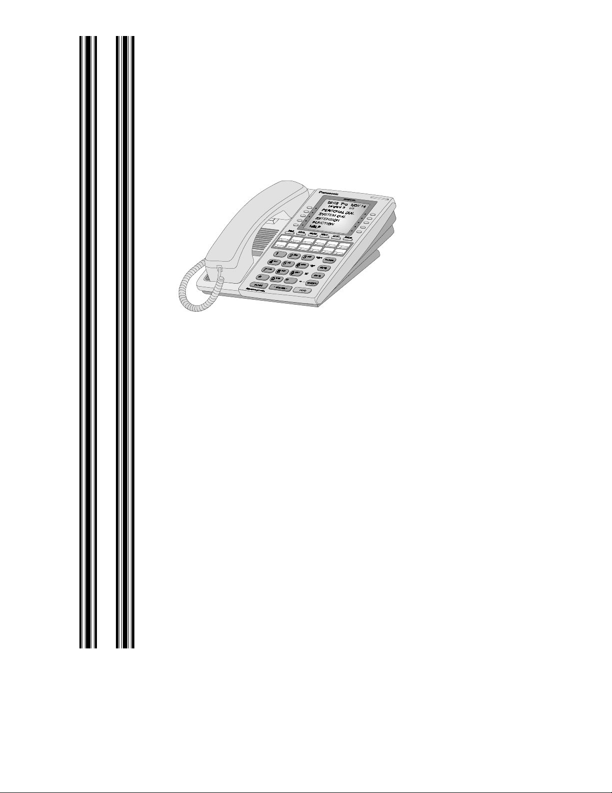
DBS CALLER ID
INSTALLATION
AND OPERATION
Panasonic
Panasonic
PanasonicPanasonic
®®®®
Please read these instructions completely before operating this unit.
Section 510
Issued April 2000
Part Number 550X03401
© Panasonic Telecommun i cation Systems Company. All ri ghts reserved.
Unauthorized cop ying and distribution is a violat ion of law.
Page 2

Warning: This service information is designed for
experienced repair technicians only and is not
designed for use by the general public. It does not
contain warnings or cautions to advise non-technical
individuals of potential dangers in attempting to service a product. Products powered by ele ctricity should
be serviced or repaired only by experienced professional technicians. Any attempt to service or repair
the product or products dealt with in thi s ser vi ce inf or mation by anyone else could resu lt in seri ous inju ry or
death.
The contents of this manual are subject to change without notice and
do not constitute a commitment on the part of Panasonic
Telecommunication Systems Company (PTSC). Every effort has
been made to ensur e t he ac cur acy of this document. Howe ver, due t o
ongoing product improvements and revisions, Panasonic cannot
guarantee the accuracy of printed material after the date of
publication nor can it accept responsibility for errors or omissions.
Panasonic will update and revise this document as needed.
The software and hardware described in this document may be used
or copied only in accordance with the terms of the license pertaining
to said soft ware or hardware.
Reproduction, publication or duplication of this manual, or any part
thereof, in any manner, mechanically, electronically, or
photographically is prohibited without permission of the Panasonic
Telecommunication Systems Company (PTSC).
© Copyright 2000 by Panasonic Telecommunication Systems
Company
All rights reserved.
Page 3

Contents
About this Manual
Overview.............................................................................................v
Related Documents .............................................................................v
Chapter 1. An Introduction to Caller ID
Overview ........................................................................................ 1-3
A Definition of Caller ID.......................................................... 1-3
How the DBS Receives and Processes Caller ID..................... 1-3
Overview of DBS Caller ID Features ......................................1-4
Pre-Installation Requirements ........................................................1-6
Hardware and Software Requirements ....................................1-6
Ordering Caller ID ...................................................................1-6
Chapter 2. Installation and Programming
Installation.......................................................................................2-3
Programming .................................................................................. 2-5
General Caller ID Setup ...........................................................2-5
Flexible Display of Caller ID Information ............................... 2-5
Call Log Indication Key...........................................................2-6
Call Log....................................................................................2-7
Caller ID Auto DISA Programming.........................................2-8
Chapter 3. Operation
Descriptions of DBS Caller ID Features.........................................3-1
Caller ID Display........................................................ ......... .....3-1
Flexible Display of Caller Information.....................................3-2
Caller ID Call Log....................................................................3-3
Caller ID via SMDR.................................................................3-8
Caller ID/Auto DISA........................................................... .....3-8
Issued April 2000 iii
Page 4

Contents
This page intentionally left blank.
iv Issued April 2000
Page 5

About This Manual
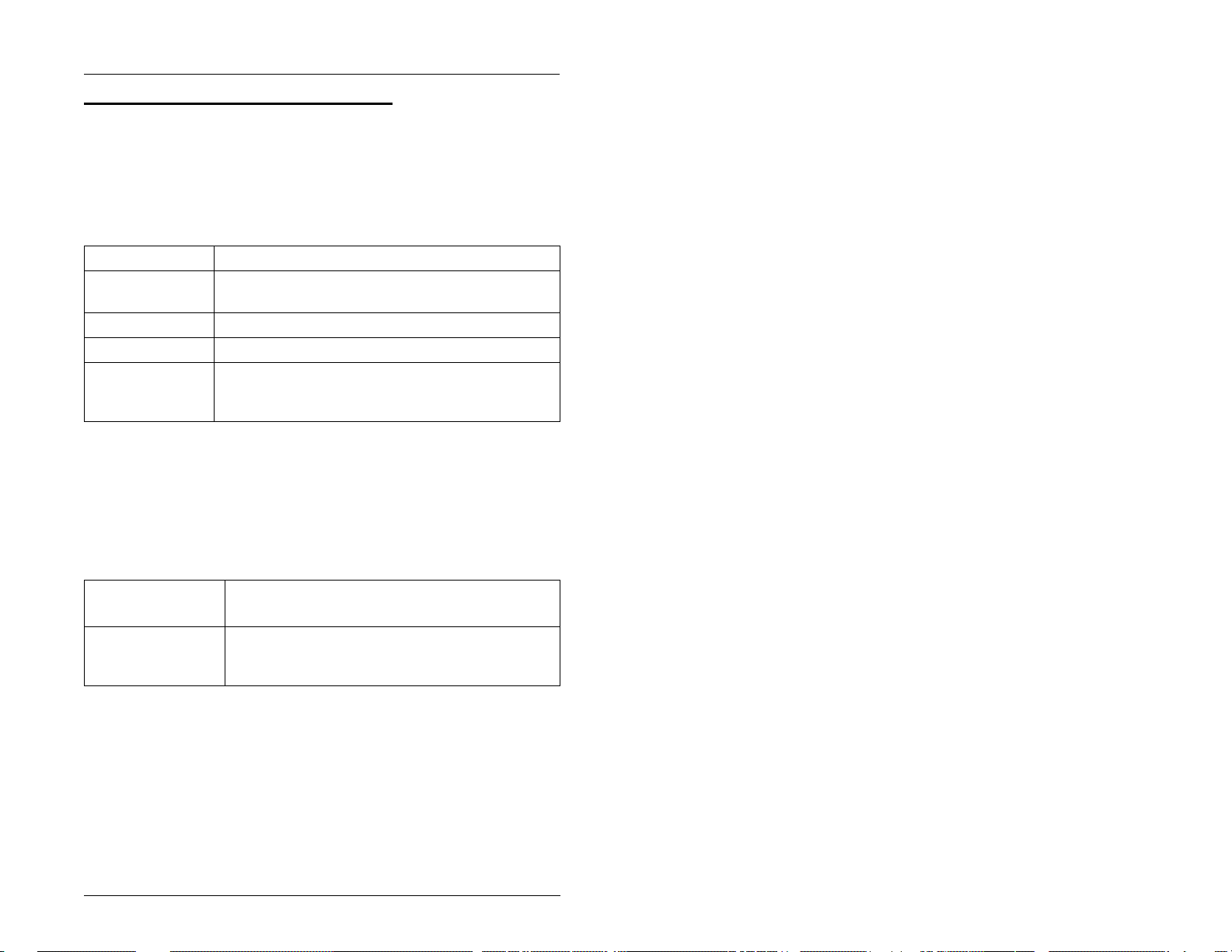
Overview
This manual provides an overview of Caller ID, along with
installation, programming, and operation instructions. The
following table summarizes each chapter contained in this
manual.
Section Title Purpose
Chapter 1Introduction
to Caller ID
Chapter 2Installation
and Programming
Chapter 3Operation Describes how end users can view and
Provides an overview of Caller ID,
plus information on pre-installation
requirements.
Provides step-by-step instructions on
installing the Caller ID card and summarizes the programs that are essential to Caller ID operation.
access Caller ID data on their display
phones.
Related Documents
For general instructions on DBS hardware installation, see
Installation (Section 300)
programming, see
Programming Guidance (Section 400)
Issued April 2000 v
. For an intr oduction to DBS
.
Page 6

About This Manual
This page intentionally left blank.
vi Issued April 2000
Page 7
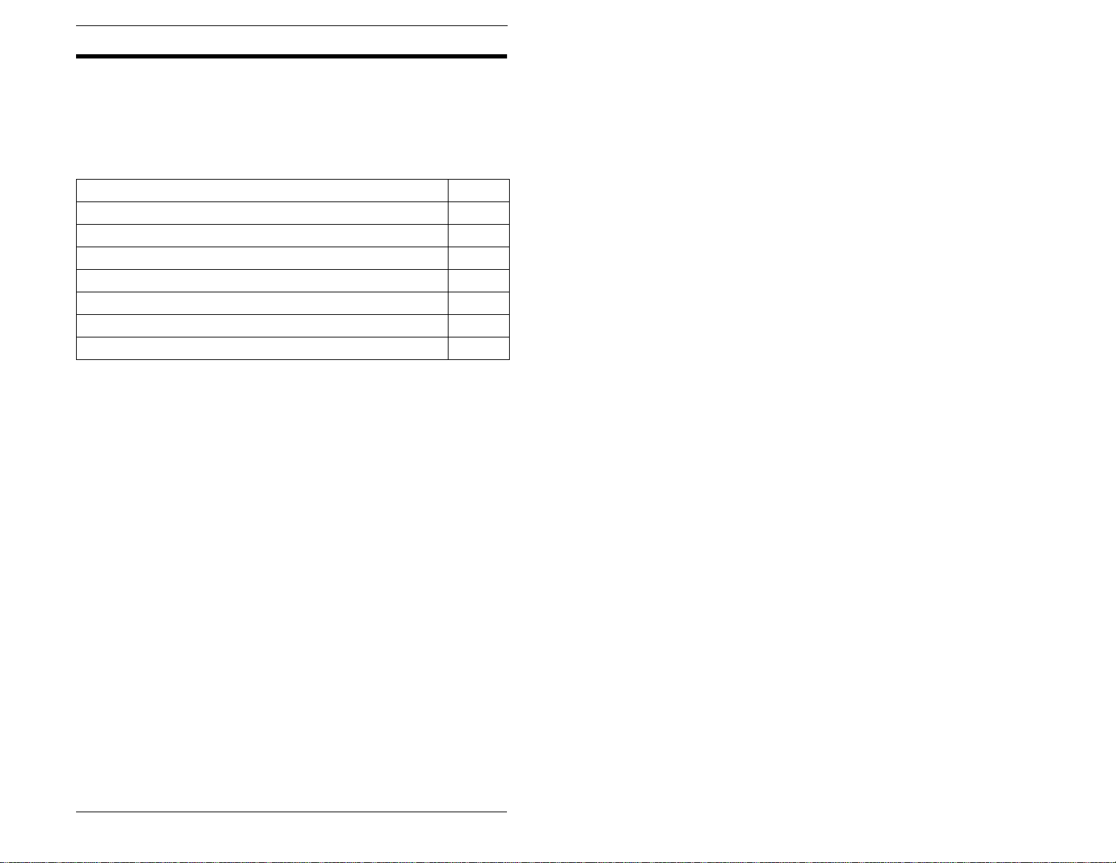
Chapter 1. An Introduction to Caller ID
This chapter provides an overview of Caller ID, plus information on
pre-installation requirements.
The following table summarizes the topics contained in this chapter.
Topic Page
Overview 1-2
A Definition of Caller ID 1-2
How the DBS Receives and Processes Caller ID 1-2
Overview of DBS Caller ID Features 1-3
Pre-Installation Requirements 1-5
Hardware and Software Requirements 1-5
Ordering Caller ID 1-5
Issued April 2000 1-1
Page 8

Overview
Overview
A Definition of Caller ID
Caller ID (CID), a service offered by local central offices, sends
calling number information from the local CO to the DBS. Users who
have display telephones can see CID information as incoming calls
ring at their extension and can have access to previous calls via the
call log feature.
The type of calling number information transmitted to the DBS
depends on whether
single-data
or
multiple-data
format is used.
S
ingle-data
DBS.
and calling name. Though the DBS receives the date and time with
both formats, it does
phones. The DBS has its own internal timer.
Note
through local central offices only. Calling party information
transmitted from interexchange carriers (IXCs) uses a different
format known as Automatic Number Identification (ANI). ANI is
supported by the DBS at this time. Also, single data and multiple
not
data may be marketed by different names depending on the local
operating telephone company.
format supplies the date, time, and calling number to the
Multiple-data
: Caller ID refers to calling party information transmitted
format supplies the date, time, calling number,
transmit this information to individual key
not
How the DBS Receives and Processes Caller ID
Caller ID data is transmitted to the DBS between the first and second
incoming rings.
The Caller ID card (VB-43551) and L-TRK card (VB-43511A)
collect the data and distribute it to the appropriate extension via the
CPC card.
Since Caller ID data is not sent to the DBS until after the first ring, the
DBS waits approximately 4 seconds after the detection of the first
incoming ring to allow time for collecting Caller ID data and
1-2 Issued April 2000
Page 9

Overview
processing before it rings the appropriate extension and sends the
Calling ID data for display.
The DBS processes Caller ID as follows:
• The CO sends a Caller ID call to the CID card/loop-start trunk.
• The CID card begins collecting the Caller ID data 30 ms after
the initial incoming ring ends.
• The loop-start trunk sends a signal to the CPC card indicating
that a call is coming in.
• When the CPC card receives the incoming call notification, it
lights the FF key(s) for the trunk red.
• The Caller ID data is transmitted to the CPC card.
• The CPC card then transmits the Caller ID call and data to the
appropriate digital extension. The FF k ey changes to green and
the extension rings. (The trunk FF key lights red for
approximately 4 seconds before the extension receives the call.
This is due to the time required by the Caller ID data receiving
and processing steps.)
Overview of DBS Caller ID Features
This section provides an overview of the Caller ID features provided
by the DBS. A more complete description of the features and their
operation is provided in “Operation” in Chapter 3. Programming
procedures for these features can be found in “Installation and
Programming” in Chapter 2. (Not all features require programming.)
Caller ID Display
The Caller ID display shows the Caller ID number and/or name,
depending on the Caller ID format used.
Once Caller ID information is received, it can be transmitted to
another phone through call transfer, call forwarding, etc.
Issued April 2000 1-3
Page 10

Overview
The following illustration shows how a Caller ID call appears on the
phone display.
Figure 1-1. Example Caller ID display.
404-555-5512
First line: calling number (7 or 10 digits)
ABC COMPANY
Second line: calling name (up to 15 characters)
Flexible Display of Caller Information
With the introduction of Caller ID, the DBS provides a new timer that
controls how long incoming call information is displayed.
This new timer ensures that Caller ID information is displayed long
enough to provide ample viewing time without forcing the user to
start the call record too late.
Caller ID Call Log
The Call Log keeps a record of Caller ID calls to individual key
phones. Accessing the Call Log allows users to view Caller ID calls
that have been sent to their phone.
Users can assign an FF key to flash when there are new entries in the
log. When the user presses the key to access the log, the LED turns
off.
Caller ID via SMDR
Caller ID information is transmitted to the SMDR port. Incoming
Caller ID number and name is recorded in the dialed number field.
The call type is Incoming as indicated by an “I”.
Caller ID Auto DISA
This feature provides automatic DISA dial tone based on Caller ID
information (not DISA trunk type). The purpose of the automatic
DISA dial tone is to provide easy access to the remote programming
mode through DISA.
1-4 Issued April 2000
Page 11
Pre-Installation Requirements
Pre-Installation Requirements
Hardware and Software Requirements
The following hardware and software are required for Caller ID.
Equipment Model Number
Loop-start trunk
card
Caller ID card VB-43551
MFR Card VB-43431 (for Caller ID Auto DISA)
CPC Card VB-43411 (CPC-B; must be version 6.1 or higher)
Ordering Caller ID
The following guidelines describe Caller ID options that can be
ordered from your local operating company or interexchange carrier.
VB-43511A (8 ports)
or
VB-43412 (CPC-A II; must be ve rsio n 6. 1 or hi gher)
Table 1-1. Guidelines for ordering T1 services
Item to be
Ordered Options
Line Type Single-party loop start lines. (As an alternative,
you may want to add Caller ID to existing singleparty loop start lines.)
Issued April 2000 1-5
Page 12

Pre-Installation Requirements
Item to be
Ordered Options
Ringing Type Standard ringing.
damage to the Caller ID Circuits
Caller ID Either
single-data
ordered.
Single-data format supplies the date, time, and
calling number to the DBS. Multiple-data format
supplies the date, time, calling number, and calling
name. Though the DBS receives the date and time
with both formats, it does
mation to individual key phones.
Some central offices may not offer both
Note:
Caller ID formats. Make certain that the order of
the information for
calling number and the order of information for
multiple-data
calling name.
Distinctive ringing may cause
.
or
multiple-data
not
single-data
is date, time, calling number and
format may be
transmit this infor-
is date, time, and
1-6 Issued April 2000
Page 13

Chapter 2. Installation and Programming
This chapter describes installation and programming
for Caller ID.
The following table summarizes the topics contained
in this chapter.
Topic Page
Installation 2-3
Programming 2-5
General Caller ID Setup 2-5
Flexible Display of Caller ID Information 2-5
Call Log Indication Key 2-6
Call Log 2-7
Caller ID Auto DISA Programming 2-8
Issued April 2000 2-1
Page 14

Installation
Installation
The following pro cedure describes the hardware
setup required for Caller ID.
1. Remove the cover from the L-TR K card (VB-
43511A).
2. Cut strap J1 on the L-TRK card.
Figure 2-1. L-TRK Card Strap J1 an d Switch Locations
SW2
ON ON ON ON
TK1
ON ON ON ON
SW1 SW3
SW4 SW6 SW8
TK2 TK3 TK4 TK5 TK6 TK7 TK8
SW5
L-TRK Card
(VB-43511A)
SW7
ON
When a CallerID Card Is Installed,
Set All Switches to the
ON
When No Caller ID Card Is Installed,
Set All Switches to theONPosition
Strap J1
OFF
must be
cut to
receive
Caller ID
Position
J1
2-2 Issued April 2000
Page 15

Installation
3. Set switches SW1 through SW8 on the L-TRK card
(VB-43511A) to OFF.
IMPORTANT: You must correctly set the
switches to prevent possible damage to
the L-TRK card. Also, the Tip and Ring
leads are polarity sensitive. Make sure
these are wired correctly.
4. Attach the Caller ID card to the L-TRK card.
Figure 2-2. Attaching Caller ID Card to the L-TRK Card
Caller
ID Board
(VB-43551)
L-TRK Card
(VB-43511A)
5. Replace the cover on the L-TRK card.
Issued April 2000 2-3
Page 16

Programming
Programming
The following procedures describe the programming
required for Caller ID setup. In addition, these
procedures can also be used to reconfigure the
Caller ID feature once it is operational.
Note: In the following progra mming procedures,
default settings appear in bold.
General Caller ID Setup
1. Assign the appropriate loop-start trunks as Caller
ID trunks.
Program
Name
Address FF2 (1-6 4) # 21# (0-4)#
Options 0=Loop start
Note: The DBS must be powered off and on for this
program to take effect.
Flexible Display of Caller ID Information
1. Determine if the Call Duration Display will be used.
Trunk Type
1=Ground start
2=DID
3=T1
4=Caller ID
If used, the Call Duration Time will replace the
Caller ID information on the display after a
specified time. The specified time is
2-4 Issued April 2000
Page 17

Programming
determined by Step 2 of this proced ure (FF1 2#
1# 38#)2 .
Program
Name
Address FF1 2# 1# 1# (0 or 1)#
Options 0=Call duration is not displayed
2. If the Call Duration Display is used, set the Call
Duration Timer.
This timer determines how long the Caller ID
information will be displayed before the Call
Duration Time appears. For example, if the
Call Duration Timer is set to 30 seconds, Caller
ID information will appear on the display for 30
seconds. At the end of 30 seconds, the Caller
ID information will be replaced by the Call
Duration Time.
Program
Name
Address FF1 2# 1# 38# (0, 1, or 2)#
Call Duration Display
1=Call duration is displayed
Call Duration Timer
Issued April 2000 2-5
Page 18

Programming
Options 0=5 seconds
1=16 seconds
2=30 seconds
Notes 1 . Prior to CPC-A II 6.1 and CPC-B
6.1, the SMDR Display Start Timer
(FF1 2# 1# 2#) determined when the
call duration display and the SMDR call
record began. W ith 6 .1, the S MDR Display Start Timer only cont ro l s w hen th e
DBS begins the call record.
2. The Call Duration Timer must be set
to a time equal to or greater than the
SMDR Start Timer for the Call Duration
Time to display.
3. The Call Duration Timer determines
when the call duration display begins
for all types of trunk calls, not just Caller
ID calls.
Call Log Indication Key
1. Assign the Call Log Indication Key using one of the
following two methods:
Note: The default FF Key assignment must be
cleared before you can assign a Call Log key.
Method 1
Program
Name
2-6 Issued April 2000
FF Key Assignments for Extensions
Page 19

Programming
Address FF5# (1-144)# (1-24)# CONF *6#
Note The FF11 key is used to enter the
asterisk.
or
Method 2
Programming Command
Call Log
1. Assign the Call Log feature to individual key
phones.
Programming Command
Options NNN=Extension Number
Notes 1. This command must be perfor med at
PROG FF Key *6 HOLD
PROG #96 NN(N) HOLD
each phone to be assigned the call log
feature.
2. Before entering this programming
command, you must first enter the pro-
gramming authorization code (#98
9999 is the default).
3. To delete a Call Log assignment,
enter:
PROG #96 NN(N) CONF.
Issued April 2000 2-7
Page 20

Programming
Caller ID Auto DISA Programming
1. Assign up to 10 phone numbers for the CID
Automatic DISA tab le. When one of t hese numbers
is received by the Caller ID feature, the trunk
automatically switches to DISA.
Program
Name
Command FF1 2# 8# (1-10) (Phone Number)#
Options Up to 10 number assignments (1-10)
Notes 1. Do not assign the trunk as a DISA
Automatic DISA
are available.
trunk.
2. The phone number may be up to 10
digits. The number entered must
exactly match the number received by
Caller ID (usually 10 digits).
2-8 Issued April 2000
Page 21

Chapter 3. Operation
Descriptions of DBS Caller ID Feature s
This section provides descriptions of Caller ID
features provided by the DBS. Programming
procedures for these features can be found in
“Installation an d Prog ram ming i n Chap ter 2. (N ot al l
features requir e pr ogramming.)
Caller ID Display
Caller ID displ ays on all phones that the Caller ID
trunk rings. This includes:
• DISA calls
• Transferred cal ls
• Forwarded calls
• Coverage calls
• Hold recalls (when a call is on hold, the trunk
number or name di splays)
• Transfer recalls
• Reversion calls to the attendant
• Calls that are picked up through BLF keys
• Calls that are picked up with direct call pickup
• Calls that are picked up with group call pick up
Issued April 2000 3-1
Page 22

Operation
• Calls to a hunt group pilot number and hunt
group members .
The Caller ID display shows the Caller ID name and/
or number, depending on the Caller ID format used.
3-2 Issued April 2000
Page 23

The following illustration shows how a Caller ID call
g
)
appears on the phone display.
Figure 3-1. Example Caller ID display.
Operation
404-555-5512
ABC COMPANY
Flexible Display of Calle r Infor m ation
Prior to Caller ID, the SMDR Display Start Timer
controlled two functions:
Note: Due to pr ocessing and timing limitations,
some of the last characters in a name may not
appear when the phone first rings. These
characters are writte n to the displa y as soon as
they are received at the phone. If the phone is
answered before the complete name is
displayed, the truncated name appears on the
call log.
• When incoming trunk name/number wa s
replaced by call dura tion time
First line: calling number (7 or 10 di
Second line: calling name (up to
15 characters
• When the SMDR call record began.
With the introduction of Caller ID, th e SM DR Display
Start Timer only controls when the SMDR call record
begins. A new timer, the Call Duration Timer,
controls how long incoming call information is
displayed. This new timer ensures that Caller ID
information is displayed long enough to provide
Issued April 2000 3-3
Page 24

Operation
ample viewing time without forcing the user to start
the call record too late.
For programming information on Fle x ible Caller
Information Display, see “General Caller ID Setup”
on page 2-4.
Note: The new Call Duration Timer controls all the
calling information display for all trunks, not just
Caller ID trunks.
Caller ID Call Log
The Call Log keeps a record of Caller ID calls to
individual phone s. The Call Log allo ws users to view
Caller ID calls that have been sent to their phone.
Users can assign an FF key to flash when there are
new entries in the log. When the user presses the
key to access the log, the LED turns off.
Call Logs can be assigned to both attendant and
non-attendant extensi ons. The following table shows
maximums for the number of entries that can be
stored for each type of extension. The table als o
shows the total number of entries that can be stored
system wide.
Table 3-1. Call log maximums
Call Log Maximums Maxi-
mum
Maximum number of attendant extensions 4
3-4 Issued April 2000
Page 25

Operation
Maximum number of non-attendant extensions
Maximum number of all types of extensi ons 19
Number of log entries that can be stored for
an attendant extension. (After the call log fills
with 25 entries, each additional entry overwrites the oldest log entry.)
Number of log entries that can be stored for
a non-attendant extensi on. (Afte r the cal l log
fills with 10 entries, each additional entry
overwrites the oldest log entry.)
Number of log entries that can be stored system wide
Types of Calls Included
The call log stores information for Caller ID calls that
ring or are answered at a phone. If the phone does
not ring (for instance when Call Forward - All Calls is
active), there is no entry in the Call Log for that call.
15
25
10
250
Call Log Information
Each Call Log entry includes the following call
information:
• Calling number
• Calling name (if provided)
• Time and date
Issued April 2000 3-5
Page 26

Operation
• How the call was answered
• How the call was routed.
Call Log Format
The most recent entries are stored first in the Call
Log. When users view the log by pre ssing the Call
Log Key, they can select a specific entry, then scroll
forward or backward through the entire contents of
the log.
Log Format for the Small-Display Phone. In addition
to viewing the calling number information by pressing
the Call Log Key, users can view the detailed
information on each en try by pressing the CONF key.
For example, when a Call Log entry is first displayed
by pressing the Call Log Key, the following
information is shown.
Figure 3-2. Call log format for the small-display phone-calling number and name
First Level
of Call Log
Information
3-6 Issued April 2000
404-555-1212 Calling number
Bill Smith
Calling name
Page 27

Operation
e
Pressing the CONF key displays the next level of
information:
Figure 3-3. Call log format for the small-display phone--
Second Level
of Call Log
Information
time and date
Pressing the CONF key again displays the n ext level
of information.
Figure 3-4. Call log format for small-display phone-answer information
Third Level
of Call Log
Information
Pressing the CONF key again displays this
information.
Figure 3-5. Call log format for small-disp lay phone--rout-
10:30 WED JUNE 22 Time, day and date
404-555-1212
ANS-J. Jones 103 How the call was handl
404-555-12 12
Calling number
Calling Number
Fourth Level
of Call Log
Information
ing information
DIRECT How the call was rout
404-555-12 12
Issued April 2000 3-7
Calling number
Page 28

Operation
Pressing the CONF key again returns the display to
the first level of call log information.
Other call log entries can be viewed by pressing the
* or # keys. A “<“ appears beside the oldest entry in
the log.
Exit the Call Log display by pressing the ON/OFF
key.
3-8 Issued April 2000
Page 29

Operation
h
Log Format for the Large-Display Phone. Largedisplay phone users can view all four levels of the
Call Log on one screen.
For example, when the large-display phone user
presses the Call Log Key, the following display
appears:
Figure 3-6. Call log format for the large-display phone-calling number
404-555-0001
ABC COMPANY
404-555-0001
404-555-8888
404-555-9999
404-555-7777
404-555-66 66
A “<“ may appear to the right side of one of the
entries. This indicates the oldest entry in the log.
By pressing the soft key next to the desired entry,
the user can view the details of a particular call.
Number of last entry viewed throug
top display
Name of last entry viewed through
top display
Number of selected entry
Number of second log entry
Number of third log entry
Number of fourth log entry
Number of fifth log entry
Issued April 2000 3-9
Page 30

Operation
p
Figure 3-7. Call Lo g format for the large-display phone-detailed call information
404-555-0001
ABC COMPANY
404-555-0001
ABC COMPANY
12:38 WED MAY 28
ANSWER
CFWD 130
Press any soft key to return to the calling number
listing format as shown in Figure 3-6.
Other Call Log entrie s can be viewed by pressing the
* or # keys. If these keys are pressed while viewing
detailed information, the detailed information is
displayed for the newly selected log entry.
Exit the Call Log display by pressing the ON/OFF
key.
Number of last entry viewed through
top display
Name of last entry viewed through to
display
Number
Name
Time, day and date
Whether the call was answered
How the call was routed
3-10 Issued April 20 00
Page 31

Operation
A
Caller ID via SMDR
In addition to displaying Caller ID informati on on
phones, Caller ID information is recorded in the
SMDR record. The following illustration shows how
the CID information is displayed in an SM DR call
record. In this example, note that the call is marked
as “Incoming,” and the Caller ID number and name
is contained in the “Dialed Digits” field.
Figure 3-8. Caller ID SMDR format
I 06/23 11:01:50 00:07.00 201 4045550001 ABC COMP
Caller ID information
I=incoming call
Caller ID/Auto DISA
Purpose
This feature provides automatic DISA dial tone
based on Caller ID in formation. This all ows
predetermined users to access the DISA feature
without requiring a trunk be left in the DISA mode.
Issued April 2000 3-11
Notes:
1. “Private” appears with calls
that have restricted Caller ID
display.
2. “Out of Area” appears wit h
calls that originated out of
the CO’s area.
Page 32

Operation
This is especially useful for access to the remote
programming mode through DISA.
To use this feature, the desired phone num bers must
be programmed in the Auto DISA Table as described
in “Caller ID Auto DI SA Pr ogrammi ng” on page 2 -8.
When a CID call is sent to the DBS, the CID number
is checked against the table. If th e numbe r is fo und,
the caller will automatically be connected to DISA
dial tone.
Limitations.
IMPORTANT: This feature requires the Caller
ID information be received in the order Date/
Time, Number and optionally Name.
Timing Interactions. According to network
specifications, Caller ID data is transmitted to
customer premise equipment between the first and
second rings. Network specifications also allow the
duration of the first ring to range between .2 and 2.2
seconds.
As shown in Figure 3-9 below, the DBS begins
collecting Caller I D data approximatel y 0.03 seconds
after the initial ring ends. With COs using longer
initial ring cycles, the collection period may elapse
before all data is collected. If all the CID data is not
collected or the da ta does not ma tch a number in the
Caller ID DISA table, the incoming call will n ot be
treated as a DISA call but w ill be treated as a regular
incoming trunk call.
3-12 Issued April 20 00
Page 33

Operation
(
)
Figure 3-9. Initial Ring Cycle Duration and Ca ller ID Data
CO 1st ring
(Range=.2 to 2.2 seconds)
CO 2nd ring
Incoming
Caller ID Call
Collection
0.03 sec
Caller ID data is collected
2.5 sec
Issued April 2000 3-13
Page 34

Operation
This page intentionally left blank.
3-14 Issued April 20 00
 Loading...