


Digital Business System
Section 500
T1
Reference
Manual
503X00501B
Revised April 2000

The contents of this manual are subject to change without notice and do not constitute a
commitment on the part of Panasonic Telecommunication Systems Company (PTSC). Every
effort has been made to ensure the accuracy of this document. However, due to ongoing product
improvements and revisions, Panasonic cannot guarantee the accuracy of printed material after
the date of publication nor can it accept responsibility for errors or omissions. Panasonic will
update and revise this document as needed.
The software and hardware described in this document may be used or copied only in accordance
with the terms of the license pertaining to said software or hardware.
Reproduction, publication, or duplication of this manual, or any part thereof, in any manner,
mechanically, electronically, or photographically, is prohibited without permission of the
Panasonic Telecommunication Systems Company (PTSC).
Copyright 1996 by Panasonic Telecommunication Systems Company (PTSC)
Revised April 2000. All rights reserved.
T-SMART and T-SERV II are registered trademarks of ADC Kentrox.
Premier is a registered trademark of U.S. Sprint.
Reference to third-party products is for information only and does not constitute an endorsement
or recommendation. Panasonic does not assume responsibility for the performance of third-party
products.

Contents
About This Manual
Overview............................................................................................................................. ix
Related Documents............................................................................................................. ix
Chapter 1. Introduction to the T1 Interface
Overview................................................................................................................................. 1-3
Description of the T1........................................................................................................ 1-3
Framing Options ............................................................................................................... 1-3
Trunk Signaling Modes .................................................................................................... 1-4
DNIS Service.................................................................................................................... 1-4
Pre-Installation Requirements................................................................................................. 1-5
Ordering T1....................................................................................................................... 1-5
What You Must Purchase ................................................................................................. 1-6
Chapter 2. Installation
Guidelines............................................................................................................................... 2-3
Hardware Requirements ................................................................................................... 2-3
Maximums ........................................................................................................................ 2-3
Trunk Assignments for Single-Cabinet Systems.............................................................. 2-5
Trunk Assignments for Double-Cabinet Systems ............................................................ 2-6
Installation Procedures.......................................................................................................... 2-12
Installing the CSU........................................................................................................... 2-12
Installing a T1 in a Single Cabinet.................................................................................. 2-14
Installing T1 in a Double Cabinet with the T1 in the Slave ........................................... 2-21
Installing T1 in a Double Cabinet with T1s in the Master and Slave............................. 2-23
Chapter 3. Quick-Start Programming
Before You Begin................................................................................................................... 3-3
Programming Initial T1 Options............................................................................................. 3-4
Minimum Programming ................................................................................................... 3-4
DNIS Programming.......................................................................................................... 3-7
Revised April 2000 DBS-2.3/9.2-500 iii

Chapter 4. Programming Reference
T1 System Settings ................................................................................................................. 4-3
System Size....................................................................................................................... 4-3
Clock Settings................................................................................................................... 4-4
System-Wide Timers .............................................................................................................. 4-7
Digital Pad Settings .............................................................................................................. 4-14
Extension Port Settings................................................................................................... 4-16
Trunk Port Settings......................................................................................................... 4-17
Master and Slave Settings..................................................................................................... 4-18
Trunk Configuration ....................................................................................................... 4-18
Trunk Signaling .............................................................................................................. 4-19
Alarm Settings ...................................................................................................................... 4-21
Alarm Descriptions......................................................................................................... 4-21
Alarm Transmission Options.......................................................................................... 4-24
Alarm Timers ................................................................................................................. 4-25
Error Counters for FF Alarm Keys................................................................................. 4-29
Alarm Relay Controls..................................................................................................... 4-32
Trunk Settings....................................................................................................................... 4-35
FF Key Settings .................................................................................................................... 4-42
Special T1 Function Codes................................................................................................... 4-43
Appendix A. CPC-EX 1.0 Updates
Appendix B. CPC-EX 2.32 Updates
iv DBS-2.3/9.2-500 Revised April 2000

List of Figures
Figure 2-1 CSU installation .............................................................................................. 2-12
Figure 2-2 SCC-B Switch 4 .............................................................................................. 2-14
Figure 2-3 Connector 4 (CN4) strapping, Sync Unit ........................................................ 2-15
Figure 2-4 T1 Sync Unit installation ................................................................................ 2-16
Figure 2-5 T1 MDF card installation ................................................................................ 2-17
Figure 2-6 Sync Unit and T1 connection, single-cabinet installation ..............................2-18
Figure 2-7 RJ48 pinouts, CN1 connector ......................................................................... 2-19
Figure 2-8 T1 cabinet connections, single-cabinet installation ........................................ 2-20
Figure 2-9 Sync cable connections, double-cabinet with a T1 in the slave ...................... 2-22
Figure 2-10 Clock sync cable and sync cable connections, double-cabinet installation ....2-24
Figure 4-1 Circuit-type numbers ......................................................................................4-14
Figure 4-2 Default pad values .......................................................................................... 4-15
Figure 4-3 Pad Nos........................................................................................................... 4-15
Figure A-1 CPC-EX ............................................................................................................. A-5
Figure A-1 Desk Stand Removal.......................................................................................... A-6
Figure A-1 Inserting the wall mount bracket (rotated desk stand) ...................................... A-6
Figure A-1 Handset guide insertion for wall mounting, key telephone ............................... A-7
Figure A-1 44-Series Small-Display Phone ......................................................................... A-8
Figure A-1 44-Series Large-Display Phone ....................................................................... A-10
Figure A-1 DSS/72 Console (VB-44320) key layout ........................................................ A-21
Figure A-1 DSS/72 #1 Default Extension Numbers .......................................................... A-22
Figure A-1 EM/24 Unit (VB-44310) keys ......................................................................... A-24
Figure A-1 CPC-EX Serial Port 2 ...................................................................................... A-29
Figure A-1 T1 Network Extension Numbering ................................................................ A-32
Figure A-1 T1 Network Call Priority Routing ................................................................... A-33
Figure A-1 SMDR Format for CPC-EX............................................................................ A-42
Revised April 2000 DBS-2.3/9.2-500 v

vi DBS-2.3/9.2-500 Revised April 2000

List of Tables
Table 2-1. EC/TRK slot usage for T1 ................................................................................ 2-3
Table 2-2. T1 and analog trunk assignments, DBS 40 ....................................................... 2-5
Table 2-3. T1 and analog trunk assignments, DBS 72 ....................................................... 2-5
Table 2-4. T1 and analog trunk assignments, DBS 96 ....................................................... 2-6
Table 2-5. Maximum T1 assignments for two-cabinet systems ......................................... 2-6
Table 2-6. T1 and analog trunk assignments, DBS 40 + 40 ............................................. 2-7
Table 2-7. T1 and analog trunk assignments, DBS 72 + DBS 72 .................................... 2-8
Table 2-8. T1 and analog trunk assignments, DBS 96 + DBS 40 .................................... 2-9
Table 2-9. T1 and analog trunk assignments, DBS 96 + DBS 72 .................................. 2-10
Table 2-10. T1 and analog trunk assignments, DBS 96 + DBS 96 .................................. 2-11
Table 2-11. Switch settings for SW1 on the T1 card ......................................................... 2-18
Table 4-1. T1 alarm definitions ........................................................................................ 4-21
Table 4-2. Alarm-related programs ..................................................................................4-22
Table 1-1. Guidelines for ordering T1 services .................................................................. 1-5
Table 1-2. T1 Hardware requirements for single-cabinet systems ..................................... 1-6
Table 1-3. T1 Hardware requirements for double-cabinet systems ...................................1-6
Table 1-4. CSU equipment required for T1 .......................................................................1-7
Table 2-1. EC/TRK slot usage for T1 ................................................................................ 2-3
Table 2-2. T1 and analog trunk assignments, DBS 40 ....................................................... 2-5
Table 2-3. T1 and analog trunk assignments, DBS 72 ....................................................... 2-5
Table 2-4. T1 and analog trunk assignments, DBS 96 ....................................................... 2-6
Table 2-5. Maximum T1 assignments for two-cabinet systems ......................................... 2-6
Table 2-6. T1 and analog trunk assignments, DBS 40 + 40................................................ 2-7
Table 2-7. T1 and analog trunk assignments, DBS 72 + DBS 72 ...................................... 2-8
Table 2-8. T1 and analog trunk assignments, DBS 96 + DBS 40 ...................................... 2-9
Table 2-9. T1 and analog trunk assignments, DBS 96 + DBS 72 .................................... 2-10
Table 2-10. T1 and analog trunk assignments, DBS 96 + DBS 96 .................................... 2-11
Table 2-11. Switch settings for SW1 on the T1 card ......................................................... 2-18
Table 4-1. T1 alarm definitions ........................................................................................ 4-21
Table 4-2. Alarm-related programs ..................................................................................4-22
Table A-1 44-Series Phones ............................................................................................. A-1
Table A-2 Small-Display Phone Features ......................................................................... A-8
Table A-3 Large-Display Phone Features ....................................................................... A-10
Table A-4 TRS Operator Access settings ....................................................................... A-38
Revised April 2000 DBS-2.3/9.2-500 vii

viii DBS-2.3/9.2-500 Revised April 2000

About This Manual
Overview
This manual provides an overview of the DBS T1 Interface, along with
installation and programming instructions. The following table summarizes
each chapter contained in this manual.
Chapter Title Purpose
1
2
3 Quick-Start
4 Programming
A CPC-EX 1.0
B CPC-EX 2.3.2
Introduction to the
T1 Interface
Installation Provides step-by-step instructions on installing the DBS T1
Programming
Reference
Updates
Updates
Related Documents
Provides an overview of the DBS T1 Interface, plus information on pre-installation requirements.
hardware.
Summarizes the programs that are essential to T1 installation.
Contains a complete list of T1 programming commands. Each
command description includes a list of the available options
and the associated programming addresses.
Provides information on feature enhancements and software
corrections included with CPC-EX 1.0 version software.
Provides information on feature enhancements and software
corrections included with CPC-EX 2.32 version software.
For general instructions on DBS hardware installation, see Installation
(Section 300). For an introduction to DBS programming, see Programming
Guidance (Section 400).
Revised April 20 00 DBS-2.3/9.2-500 ix

x DBS-2.3/9.2-500 Revised April 2000

Chapter 1. Introduction to the T1 Interface
This chapter provides an overview of the T1 Interface. It also describes preinstallation requirements for the T1.
The following table summarizes the topics contained in this chapter.
Topic Page
Overview 1-3
Description of the T1 1-3
Framing Options 1-3
Trunk Signaling Modes 1-4
DNIS Service 1-4
Pre-Installation Requirements 1-5
Ordering T1 1-5
What You Must Purchase 1-6
Revised April 2000 DBS-2.3/9.2-500 1-1

1-2 DBS-2.3/9.2-5 00 Revised April 2000

Introduction to the T1 Interface Overview
Overview
Description of the T1
The T1 Interface is a digital trunk card that provides 24 voice channels over a
four-wire circuit.
T1 lines can be leased from local exchange carriers and long-distance
carriers.
Note: The current version of the T1 supports voice communications only.
Data can be transmitted only if it reaches the T1 in analog form. Examples of
analog data that can be transmitted over the T1 include fax transmissions or
PC files that have been converted into analog form using a modem.
Framing Options
The T1 Interface takes an 8-bit sample from each of the 24 voice channels.
These samples are grouped into 24 time slots, and each group of 24 slots is
known as a T1 frame.
Since each of the 24 time slots contains 8 bits, the number of s ampling bi ts i n
each frame equals 192 (24 x 8 = 192). In addition, a framing bit is added to
the end of each frame to mark where the frame ends. The addition of the
framing bit results in a 193-bit frame.
The T1 transmits these 193-bit frames at a rate of 8000 per second. The total
number of frames (193) multiplied by the frame speed (8000 per second)
results in a total transmission rate of 1.544 Mbps.
The T1 transmits the frames in groups of 12 or 24, depending on whether the
SF or ESF framing format is used.
SF or ESF Framing Formats
The superframe (also known as SF or D4) format transmits the sampling
frames in groups of 12. “Robbed bit signaling” is used to transmit signaling
information for the frames. With robbed bit signaling, the eighth bit of each
of the 24 samples is robbed from every sixth frame. The robbed bits transmit
signaling states such as “onhook” and “offhook.”
The extended superframe (ESF) format also uses robbed bit signaling, but
transmits the sampling frames in groups of 24. ESF supports monitoring and
maintenance capabilities that are not available with the SF format.
Revised April 2000 DBS-2.3/9.2-500 1-3

Overview
Trunk Signaling Modes
The T1 provides the following trunk signaling modes. The signaling modes
can be assigned on a per-channel basis.
• Loop start
• Ground start
•E&M
DNIS Service
The DBS T1 can be used for Dialed Number Information Service (DNIS).
DNIS is normally used when multiple 1-800 lines terminate to the same
station or group. DNIS displays the last four digits of the dialed number,
thereby allowing users to customize greetings for calls to different numbers.
Introduction to the T1 Interface
For example, an ACD group for ABC company may receive calls for sales
and service. If the 1-800 number for sales is 1-800-555-4000 and the 1-800
number for service is 1-800-555-5000, the agents will know how to answer a
ringing call by viewing their phone display. For instance, calls to the 4000
number may be answered “ABC Company--Sales Information,” while calls to
the 5000 number may be answered “ABC Company--Customer Service.”
DNIS can be assigned on a per-channel basis.
1-4 DBS-2.3/9.2-500 Revised April 2000

Introduction to the T1 Interface Pre-Installation Requirements
Pre-Installation Requirements
Use the following guidelines to prepare your site for T1 installation.
Ordering T1
The following guidelines describe T1 options that must be ordered from your
central office or interexchange carrier. These guidelines are designed to cover
almost all T1 installations. However, special requirements should be
discussed with your provider.
Table 1-1. Guidelines for ordering T1 services
Item to be Ordered Options
Line Type E&M, loop start, or ground start. For DNIS, order E&M with
wink start.
Trunk Signaling Wink start or immediate start/ringdown. Immediate start/ring-
down is used in most cases. However, if DNIS is used, order wink
start.
Signaling Code DS-1
Line Code AMI or B8ZS. AMI is used in most cases.
Framing Format D4 (Superframe) or ESF (Extended Superframe). D4 is used in
most cases.
Signaling Method In-band
Tones Order dial tone and ringback tone if provided by the CO.
Note: If the CO does not provide dial tone, program the DBS to
generate its own dial tone. See page 4-39.
DNIS Service Order E&M trunk emulation with wink start signaling.
When the central of fice se nds a DID/DNIS ca ll to the DBS, it f irst
receives a wink from the DBS before sending the digits. Once the
wink is received, the central office should wait at least 200 ms
before sending the digits. Be sure to request the delay when order-
ing DNIS.
Note: The DBS supports four-digit DNIS service only.
Revised April 2000 DBS-2.3/9.2-500 1-5

Pre-Installation Requirements
What You Must Purchase
The following items must be purchased to install T1.
DBS Equipment
If you are installing the T1 in a single-cabinet system, order the equipment
included in Table 1-2. For two-cabinet systems, see Table 1-3.
Table 1-2. T1 Hardware requirements for single-cabinet systems
Introduction to the T1 Interface
CPC-B 4.0
(VB-43411)
1
(See Note 1.)
SCC-B
(VB-43421)
1
(See Notes 2 and 3.)
T1 Trunk Card
(VB-43561)
111
T1 MDF Card
(VB-43562)
Sync Unit
(VB-43563)
Notes:
1. Version 1.3 of the Bus Processor Unit (BPU) chip is required for T1.
2. An MFR card is required for DID/DNIS if DTMF signaling is used. If DID/DNIS is
provided through DP signaling, an MFR card is not required.
3. SCC-B with ROM 1.3 or later is required if the central office does not provide T1
dial tone.
Table 1-3. T1 Hardware requirements for double-cabinet systems
T1
Location
T1 in the
Master
T1 in the
Slave
T1 in both
Master and
Slave
Notes:
CPC-B V4
(VB-43411)
(See Note 1.)
1 1 1110 1
1 11111 1
1 12211 1
SCC-B
(VB-43421)
(See Notes
2 and 3.)
T1 Trunk
Card
(VB-43561)
T1 MDF
Card
(VB-43562)
Sync
Unit
(VB-43563)
1. Version 1.3 of the Bus Processor Unit (BPU) chip is required for T1.
T1 Cable
(VB-43564)
Cable Kit
(VB-43110)
(See Note 4.)
2. An MFR card is required for DID/DNIS if DTMF signaling is used. If DID/DNIS is provided through DP
signaling, an MFR card is not required.
3. SCC-B with ROM 1.3 or later is required if the central office does not provide T1 dial tone.
4. Version 1.2 of the Cable Kit is required for T1.
1-6 DBS-2.3/9.2-500 Revised April 2000

Introduction to the T1 Interface Pre-Installation Requirements
CSU Equipment
The installer must provide a Channel Service Unit (CSU) plus CSU cabling.
The CSU equipment must meet the specifications contained in T able 1-4. See
page 2-12 for instructions on installing the CSU.
Table 1-4. CSU equipment required for T1
Item Specifications Vendors
CSU The Channel Service Unit (CSU) must comply with
FCC Part 15 and Part 68. The CSU is installed
between the DBS and the publ ic networ k. The C SU
provides alarm, diagnostic, and monitoring functions, as well as network protection.
The following CSUs have been used successfully
with the DBS T1.
Kentrox
For the D4 framing format:
Kentrox T-SERV II
For the D4 or ESF framing format:
Kentrox T-SMART
(Kentrox can be contacted at 1-800-733-5511.)
CSU
Cabling
Each CSU requires a network cable and an equipment cable. The network cable connects from the
CSU to the network interface. The equipment cable
connects from the CSU to the DBS T1 MDF card.
For Kentrox CSUs
The network cable requires a female DB-15 connector and an RJ48C connector. The equipment
cable requires a male DB-15 connector and an
RJ48C connector.
To simplify installation, you can order the prefabricated cables shown in the “Vendors” column.
If you fabricate your o wn T1 cables, you shou ld use
24 AWG stranded cable that includes shielding for
each pair. For best results, use the cable listed un der
“Vendors.”
For Premier CSUs
You must fabricate your own cables for the Premier
CSU. The network cable requires two RJ48C connectors. The equipment cable connects to an RJ48C
connector on the T1 MDF card and to four screwdown terminals on the CSU.
For both cables, use 24 AWG stranded cable that
includes shielding for each pair. For best results,
use the cable listed under “Vendors.”
Premier
For the D4 or ESF format:
Premier PT-3000-01
(Premier is manufactured by U.S. Sprint. Sprint
can be contacted at 1-800-791-1110.)
For Kentrox CSUs
Kentrox offers prefabricated cables f or their CSUs.
For the network cable, order part number 01-
93010151. For the equipment cable, order part
number 01-93010121.
If you fabricate your own cables, use 24 AWG
stranded cable that includes shielding for each pair.
Belden (Richmond, IN) offers stranded cable that
complies with these specifications. Order part
number 8723.
For Premier CSUs
Belden (Richmond, IN) offers stranded cable that
complies with our specifications. Order part number 8723.
Revised April 2000 DBS-2.3/9.2-500 1-7

1-8 DBS-2.3/9.2-5 00 Revised April 2000

Chapter 2. Installation
This section describes guidelines and procedures for installing the T1
Interface. Once the T1 is installed, refer to “Quick-Start Programming” on
page 3-1 for programming instructions.
This chapter covers the following topics:
Topic Page
Guidelines 2-3
Hardware Requirements 2-3
Maximums 2-3
Trunk Assignments for Single-Cabinet Systems 2-5
Trunk Assignments for Double-Cabinet Systems 2-6
Installation Procedures 2-12
Installing the CSU 2-12
Installing a T1 in a Single Cabinet 2-14
Installing T1 in a Double Cabinet with the T1 in the Slave 2-21
Installing T1 in a Double Cabinet with the T1 in the Slave 2-21
Revised April 2000 DBS-2.3/9.2-500 2-1

2-2 DBS-2.3/9.2-5 00 Revised April 2000

Installation Guidelines
Guidelines
Read the following guidelines before beginning T1 installation. Installation
instructions begin on page 2-14.
Hardware Requirements
• The system configuration determines what cards and cables must be
purchased for T1. See “DBS Equipment” on page 1-6 for more
information.
• The installer must provide a Channel Service Unit (CSU) that complies
with FCC Part 15 and Part 68. The CSU is installed between the DBS and
the public network. The CSU provides alarm, diagnostic, and monitoring
functions, as well as network protection.
See “CSU Equipment” on page 1-7 for details on purchasing CSUs.
Maximums
• One T1 card can be installed per cabinet; the T1 card must be installed in
the “EC/TRK” slot.
• The number of T1 cards that can be installed in two-cabinet systems
depends on the sizes of the connected systems. Table 2-1 shows T1
maximums for two-cabinet systems.
Note: The DBS 72 + DBS 40 combination does not support T1.
Table 2-1. EC/TRK slot usage for T1
System Size EC/TRK Slot
Usage for T1
Master Slave
DBS 40 + DBS 40 No Yes
DBS 72 + DBS 40 No No
DBS 72 + DBS 72 No Yes
DBS 96 + DBS 40 Yes Yes
DBS 96 + DBS 72 Yes Yes
DBS 96 + DBS 96 Yes Yes
Revised April 2000 DBS-2.3/9.2-500 2-3

Guidelines
Installation
• Fractional T1 can be used when fewer than 24 T1 trunks are needed.
Fractional T1 allows you to use only a portion of the 24 channels provided
on the T1 card.
• Though each T1 Interface provides 24 trunk channels, T1 trunks do not
increase the overall trunk capacity of the DBS. Each T1 channel subtracts
from the total number of analog trunks that can be installed. Furthermore,
the number of analog trunks that can be used are always decremented in
quantities of 8.
For instance, if you’re installing a T1 in a DBS 96 and you only want to
use 12 T1 channels, the logical number of analog trunks that would be
available is 20 (32 - 12 = 20).
However, because the number of analog trunks must be decremented in
quantities of 8, the actual number of analog trunks that can be used is 16:
(32 total trunks - 16 (two 8-trunk increments) = 16.)
Tables 2-2 through 2-4 show the possible combinations of analog and
digital trunks assignments based on system size.
The trunk numbering shown in these tables is determined by backplane
trunk port assignments. Therefore, the numbering cannot be changed.
Note: Analog trunks are numbered beginning with “1.” T1 trunk channels
are numbered beginning with the highest trunk channel used.
2-4 DBS-2.3/9.2-500 Revised April 2000

Installation Guidelines
Trunk Assignments for Single-Cabinet Systems
• Programming is not required to associate trunk ports with slot locations.
However, you must use programming to specify that a combination of T1
and analog trunks is installed, and you must also specify how many T1
channels are used.
Table 2-2. T1 and analog trunk assignments, DBS 40
Trunk
Number
1 T1 channel 16 Analog trunk 1
↓↓ ↓
8 T1 channel 9 Analog trunk 8
9 T1 channel 8 T1 channel 8
↓↓ ↓
16 T1 channel 1 T1 channel 1
Note: Since the DBS 40 supports a maximum of 16 trunks,
all 24 channels of the T1 cannot be used.
Table 2-3. T1 and analog trunk assignments, DBS 72
Trunk
Number
1 T1 channel 24 Analog trunk 1 Analog trunk 1
↓↓ ↓ ↓
8 T1 channel 17 Analog trunk 8 Analog trunk 8
24-Channel T1 Fractional T1
Fractional T1
using 16 Channels
using 16 Channels
Fractional T1
using 8 Channels
Fractional T1
using 8 Channels
9 T1 channel 16 T1 channel 16 Analog trunk 9
↓↓ ↓ ↓
16 T1 channel 9 T1 channel 9 Analog trunk 16
17 T1 channel 8 T1 channel 8 T1 channel 8
↓↓ ↓ ↓
24 T1 channel 1 T1 channel 1 T1 channel 1
Revised April 2000 DBS-2.3/9.2-500 2-5

Guidelines
Table 2-4. T1 and analog trunk assignments, DBS 96
Installation
Trunk
Number
1 Analog trunk 1 Analog trunk 1 Analog trunk 1
↓↓ ↓ ↓
8 Analog trunk 8 Analog trunk 8 Analog trunk 8
9 T1 channel 24 Analog trunk 9 Analog trunk 9
↓↓ ↓ ↓
16 T1 channel 17 Analog trunk 16 Analog trunk 16
17 T1 channel 16 T1 channel 16 Analog trunk 17
↓↓ ↓ ↓
24 T1 channel 9 T1 channel 9 Analog trunk 24
25 T1 channel 8 T1 channel 8 T1 channel 8
↓↓ ↓ ↓
32 T1 channel 1 T1 channel 1 T1 channel 1
24-Channel T1 Fractional T1
using 16 Channels
Fractional T1
using 8 Channels
Tru nk Assignments for Double-Cabinet Systems
• When T1 is used in a two-cabinet system, the number of T1 channels that
can be assigned in each cabinet depends on the master/slave designation.
The following table shows the maximum number of T1 channels that can
be assigned in two-cabinet systems.
Table 2-5. Maximum T1 assignments for two-cabinet systems
System Size Master Slave
DBS 40 + DBS 40 8 analog trunks 16 T1 trunks
DBS 72 + DBS 72 16 analog trunks 24 T1 trunks
DBS 96 + DBS 40 24 T1 trunks
8 analog trunks
DBS 96 + DBS 72 24 T1 trunks
8 analog trunks
DBS 96 + DBS 96 24 T1 trunks
8 analog trunks
16 T1 trunks
24 T1 trunks
24 T1 trunks
8 analog trunks
2-6 DBS-2.3/9.2-500 Revised April 2000

Installation Guidelines
• Two-cabinet systems use the same trunk numbering scheme as singlecabinet systems: analog trunks are numbered from “1” upward; T1 trunk
channels are numbered downward from the highest channel used.
Tables 2-6 through 2-10 show trunk numbering for two-cabinet systems
using the maximum number of T1 channels.
Table 2-6. T1 and analog trunk assignments, DBS 40 + 40 (16-channel fractional T1 in the slave)
Trunk
Master Cabinet Slave Cabinet
Number
1 Analog trunk 1
↓↓ Ν/Α
8 Analog trunk 8
9 T1 channel 16
↓ N/A ↓
16 T1 channel 9
17 T1 channel 8
↓Ν/Α ↓
24 T1 channel 1
Revised April 2000 DBS-2.3/9.2-500 2-7

Guidelines
Table 2-7. T1 and analog trunk assignments, DBS 72 + DBS 72 (24-channel T1 in the slave)
Installation
Trunk
Master Cabinet Slave Cabinet
Number
1 Analog trunk 1
↓↓ Ν/Α
8 Analog trunk 8
9 Analog trunk 9
↓↓ N/A
16 Analog trunk 16
17 T1 channel 24
↓Ν/Α ↓
24 T1 channel 17
33 T1 channel 16
↓Ν/Α ↓
40 T1 channel 9
41 T1 channel 8
↓Ν/Α ↓
48 T1 channel 1
2-8 DBS-2.3/9.2-500 Revised April 2000

Installation Guidelines
Table 2-8. T1 and analog trunk assignments, DBS 96 + DBS 40 (24-channel T1 in the master; 16-
channel T1 in the slave)
Trunk
Master Cabinet Slave Cabinet
Number
1 Analog trunk 1
↓↓ Ν/Α
8 Analog trunk 8
9 T1 channel 24
↓↓ N/A
16 T1 channel 17
17 T1 channel 16
↓↓ Ν/Α
24 T1 channel 9
25 T1 channel 8
↓↓ Ν/Α
32 T1 channel 1
33 T1 channel 16
↓Ν/Α ↓
40 T1 channel 9
41 T1 channel 8
↓Ν/Α ↓
48 T1 channel 1
Revised April 2000 DBS-2.3/9.2-500 2-9

Guidelines
Table 2-9. T1 and analog trunk assignments, DBS 96 + DBS 72 (24-channel T1 in the master; 24-
channel T1 in the slave)
Installation
Trunk
Master Cabinet Slave Cabinet
Number
1 Analog trunk 1
↓↓ Ν/Α
8 Analog trunk 8
9 T1 channel 24
↓↓ N/A
16 T1 channel 17
17 T1 channel 16
↓↓ Ν/Α
24 T1 channel 9
25 T1 channel 8
↓↓ Ν/Α
32 T1 channel 1
33 T1 channel 24
↓Ν/Α ↓
40 T1 channel 17
41 T1 channel 16
↓Ν/Α ↓
48 T1 channel 9
49 T1 channel 8
↓Ν/Α ↓
56 T1 channel 1
2-10 DBS-2.3/9.2-500 Revised April 2000

Installation Guidelines
Table 2-10. T1 and analog trunk assignments, DBS 96 + DBS 96 (24-channel T1 in the master; 24-
channel T1 in the slave)
Trunk
Master Cabinet Slave Cabinet
Number
1 Analog trunk 1
↓↓ Ν/Α
8 Analog trunk 8
9 T1 channel 24
↓↓ N/A
16 T1 channel 17
17 T1 channel 16
↓↓ Ν/Α
24 T1 channel 9
25 T1 channel 8
↓↓ Ν/Α
32 T1 channel 1
33 Analog trunk 1
↓Ν/Α ↓
40 Analog trunk 8
41 T1 channel 24
↓Ν/Α ↓
48 T1 channel 17
49 T1 channel 16
↓Ν/Α ↓
56 T1 channel 9
57 T1 channel 8
↓Ν/Α ↓
64 T1 channel 1
Revised April 2000 DBS-2.3/9.2-500 2-11

Installation Procedures
Installation
Installation Procedures
The following procedures provide step-by-step instructions for installing the
CSU and the T1 Interface. The T1 procedure that you should use depends on
the type of system you have and the number of T1s you are installing.
If you’re installing ... Use this procedure...
A T1 in a single cabinet “Installing a T1 in a Single Cabinet” (page 2-14)
One T1 in a double cabinet, with the T1 located in
the master
One T1 in a double cabinets, with the T1 located in
the slave
T1s in both the master and slave “Installing a T1 in a Double Cabinet with T1s in
“Installing a T1 in a Single Cabinet” (page 2-14)
“Installing a T1 in a Double Cabinet with the T1
in the Slave” (page 2-21)
the Master and Slave” (page 2-21)
Installing the CSU
The following instructions explain how to install the CSU. See “CSU
Equipment” on page 1-7 for specifications on CSUs and CSU cabling.
Note: The CSU should be powered locally, not through the CO line. Also,
the CSU should be connected to an Uninterruptible Power Supply (UPS) to
provide battery backup in case of AC power failures.
1. Connect the equipment cable from the DBS T1 MDF card to the
equipment side of the CSU, as shown in Figure 2-1.
Figure 2-1. CSU installation
Network
Demarcation
Network
Cable
To the T1
MDF Card
CSU
DBS
Equipment
Cable
2-12 DBS-2.3/9.2-500 Revised April 2000

Installation Installation Procedures
2. Connect the network cable from the network side of the CSU to the
network demarcation point. (The network demarcation is typically an
RJ48C “smartjack.”)
3. Test the CSU cabling by performing the following steps.
Note: The following procedure can only be used with CSUs that provide a
local loopback. When testing the CSU, be sure it is set to “local loopback,”
rather than “line loopback.” Line loopback provides a loopback between
the CSU and the network.
The CSU can be tested only after the following parameters have been set.
For a summary of these parameters, see Chapter 3, “Quick-Start
Programming.” The page numbers included in the following table
reference detailed descriptions included in Chapter 4.
Parameter Page No.
System Configuration 4-3
Sync Source 4-4 to 4-6
Trunk Configuration 4-18
Frame Format 4-19
T1 Trunk Type 4-35
a. Remove the jumper from CN4 on the Sync Card (Figure 2-3 on page 2-
15).
b. Put the CSU in the local loopback mode.
c. Check the CFA LED on the T1 card. If the LED is dark, the cabling
between the CSU and DBS is okay. If the LED is lit, go to the next step.
d. Check the cabling from the DBS to the CSU.
e. If you don’t find cabling errors, take the CSU out of local loopback
mode and reinstall the jumper on CN4 of the Sync Card.
f. If the CFA LED remains lit, check the cabling from the CSU to the
network demarcation point.
Revised April 2000 DBS-2.3/9.2-500 2-13

Installation Procedures
Installing a T1 in a Single Cabinet
The following instructions explain how to install a T1 in a single-cabinet
system. These instructions also apply when a T1 is installed in only the
master cabinet of a two cabinet system.
If only one T1 is installed in a two-cabinet system, it must be installed in the
cabinet specified in Table 2-1 on page 2-3.
Note: For systems consisting of a DBS 72 connected to a DBS 40, the T1
Interface cannot be used.
1. Before beginning T1 installation, perform the “New Function Reset”
command (
be installed properly.
2. Check SW4 on the SCC-B card. Be sure it is set to “Mode B.”
Figure 2-2. SCC-B Switch 4
FF1 8# 1# 1#
).
This command must be issued before the T1 can
Installation
M ode B
(C P C -B
CPC-EX)
SCC-B C ard
ModeA
(CPC-A
CPC-AII)
SW 4
3. Check connector 4 (CN4) on the Sync Unit (VB-43563). Make sure that
Pins 2 and 3 are strapped. (See Figure 2-3.)
When Pins 2 and 3 are strapped, the Sync Unit synchronizes the DBS T1
card with the signaling provided by the public network.
2-14 DBS-2.3/9.2-500 Revised April 2000

Installation Installation Procedures
Figure 2-3. Connector 4 (CN4) strapping, Sync Unit
CN2
CN3
CN1
CN4
3
1
Free Net
4. Attach the Sync Unit to the CPC-B card.
Note: Before attaching the Sync Unit, insert the three spacers provided
with the unit and remove the jumpers from CN2 of the CPC-B card.
Revised April 2000 DBS-2.3/9.2-500 2-15

Installation Procedures
Figure 2-4. T1 Sync Unit installation
Installation
2-16 DBS-2.3/9.2-500 Revised April 2000

Installation Installation Procedures
5. Install the T1 MDF (main distribution frame) card in the top of the cabinet
as shown in Figure 2-5.
Figure 2-5. T1 MDF card installation
Revised April 2000 DBS-2.3/9.2-500 2-17

Installation Procedures
6. Set SW1 on the T1 card according to the following table.
These switch settings correspond to the distance between the DBS and the
CSU. To turn a switch on, flip it to the “up” position.
Table 2-11. Switch settings for SW1 on the T1 card
SW Distance from the DBS to the CSU
0 to 150 ft. 150-450 ft. 450-655 ft.
SW1 On Off Off
SW2 Off On Off
SW3 Off Off On
SW4 Off On Off
SW5 Off Off On
SW6 Off On Off
SW7 Off Off On
Installation
SW8 Not used Not used Not used
7. Install the T1 card in the “EC/TRK” slot
8. Connect the Sync Cable from CN1 on the Sync Unit to CN5 on the T1
card.
Figure 2-6. Sync Unit and T1 connection, single-cabinet installation
TRK
DEC
DEC DEC
DEC
DEC DEC
DEC DEC
TRK
Sync Cable
T1
SCC CPC
Sync.U nit
MFR
N
O
T
U
S
E
D
S.U .
CN1
CN5
2-18 DBS-2.3/9.2-500 Revised April 2000

Installation Installation Procedures
9. Connect the cable attached to CN3 on the T1 MDF card to CN3 on the T1
card (Figure 2-8).
10. Using an RJ48 cable, connect CN1 on the T1 MDF card to the CSU
(Figure 2-8). The following illustration shows CN1 pinouts.
Figure 2-7. RJ48 pinouts, CN1 connector
RJ48 Pin Designations
Pins Designation
1 and 2 Receive from CSU
2 and 6 No connections
4 and 5 Transmit from the
DBS
7 and 8 Frame ground
Revised April 2000 DBS-2.3/9.2-500 2-19
Installation Procedures
e
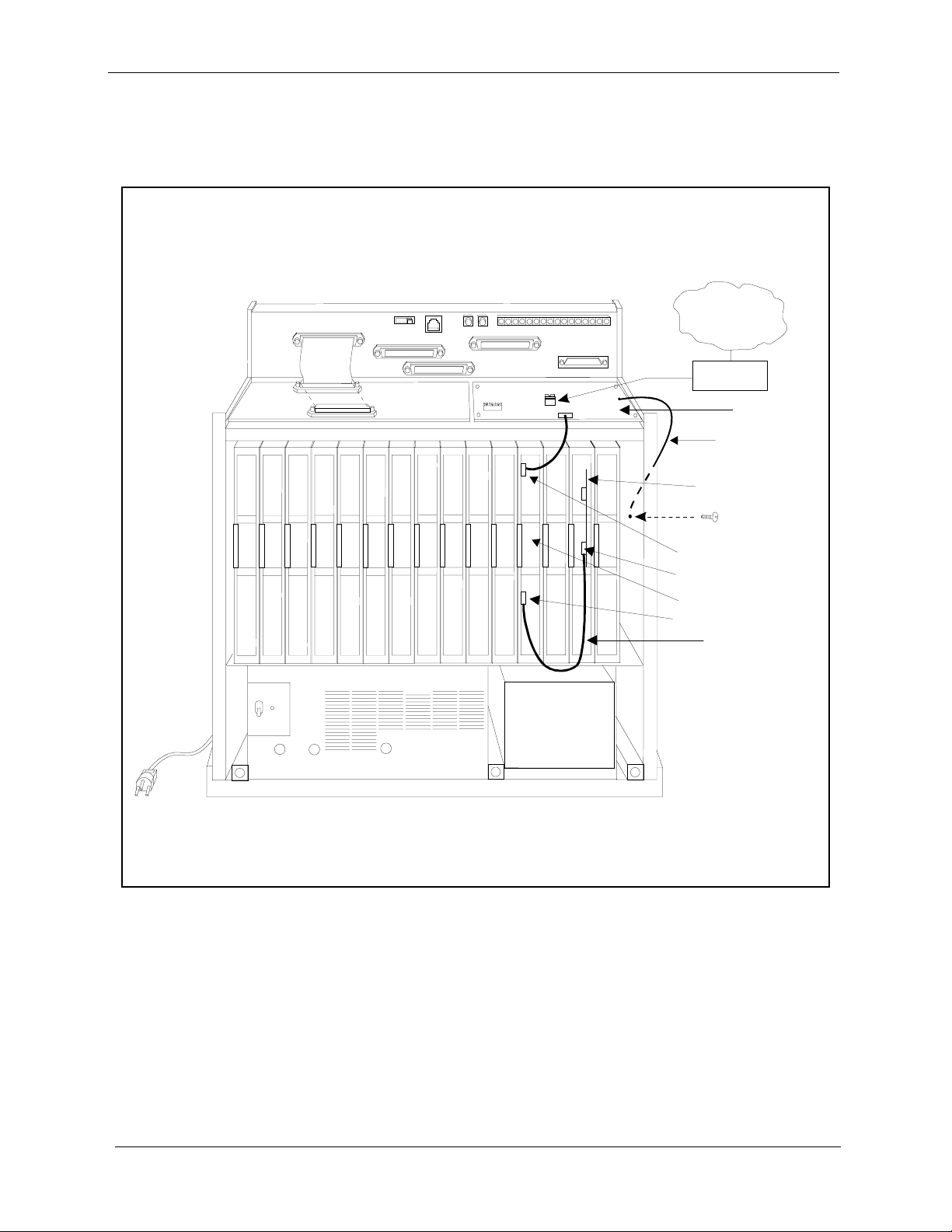
11. Connect the ground cable from the T1 MDF card to the cabinet as shown
in Figure 2-8.
Figure 2-8. T1 cabinet connections, single-cabinet installation
Installation
CN11
CN1
TRK1 TR K2 TRK3 EC1 EC2 EC3 EC4 EC5 EC6 EC7 EC8 EC/ TRK SCC CPC AUX1 AUX2
SW 1
CN12
CN3
CN5 CN4
CN13
CN14
CN1
CN2
CN6
CN3
T-1 Li ne
CSU
T-1MDF
Ground C abl
Sync Unit
CN3
CN1
T-1Card
CN5
Sync Cable
2-20 DBS-2.3/9.2-500 Revised April 2000

Installation Installation Procedures
Installing T1 in a Double Cabinet with the T1 in the Slave
1. Before beginning T1 installation, perform the “New Function Reset”
command (FF1 8# 1# 1#).
can be installed properly.
2. Check SW4 on the SCC-B card. Be sure it is set to “Mode B.” (See Step 2
on page 2-14.)
3. Install the Sync Unit in the master cabinet as described in Steps 3 and 4 on
pages 2-14 and 2-15.
4. Install a T1 MDF card in the slave cabinet. (See Step 5 on page 2-17.)
5. Set Switch 1 on the T1 card. (See Step 6 on page 2-18.)
6. Install a T1 card in the “EC/TRK” slot of the slave cabinet.
7. Connect the Sync Cable from CN1 on the Sync Unit to CN5 on the T1 card
(Figure 2-9).
This command must be issued before the T1
Note: Part Number VB-43564 is used for the Sync Cable when a T1 is
installed only in the slave cabinet of a two-cabinet system.
8. At the slave cabinet, connect the cable attached to CN3 on the T1 MDF
card to CN3 on the T1 card (Figure 2-8).
9. Using an RJ48 cable, connect CN1 of the T1 MDF card to the CSU. (See
Figure 2-7 for RJ48 pinouts.)
10. At the slave cabinet, connect the ground cable on the T1 MDF card as
shown in Figure 2-8 on page 2-20.
Revised April 2000 DBS-2.3/9.2-500 2-21

Installation Procedures
Figure 2-9. Sync cable connections, double-cabinet with a T1 in the slave
Installation
Card
Label
TRK
Guide
Slave C abinet
TRK1 TRK2 TR K3 EC 1 EC 2 EC 3 EC4 EC5 EC6 EC7 EC8 EC/ TRKSCC CPC AUX1 AUX2
DEC
DEC DEC
DEC
DEC DEC
DEC DEC
M aster Cabinet
TRK1 TRK2 TRK3 EC1 EC2 EC3 EC4 EC5 EC6 EC7 EC8 EC/ TRK SCC CPC AUX1 AUX2
TRK
T- 1 M D F
Slot Label
Connector
T1
N
O
T
U
S
E
D
MFR
MFR
CBL
2
1
(S)
CN5
Interconnection
Cables
Card
Label
Guide
DEC DEC
TRK
Note:
The num berofanalog t run ks thatc a n be
instal led depends on how m anyT1 channe lsare
use d.
DEC
DEC
DEC DEC
DEC DEC
SCC
CPC
Sync .Unit
Sync
Cable
(VB-43564)
CBL
(M)
N
O
T
U
S
E
D
CN1
2-22 DBS-2.3/9.2-500 Revised April 2000

Installation Installation Procedures
Installing T1 in a Double Cabinet with T1s in the Master and Slave
1. Before beginning T1 installation, perform the “New Function Reset”
command (FF1 8# 1# (0-1)#).
T1 can be installed properly.
2. Check SW4 on the SCC-B card. Be sure it is set to “Mode B.” (See Step 2
on page 2-14.)
3. Install the Sync Unit in the master cabinet as described in Steps 3 and 4 on
pages 2-14 and 2-15.
4. Install a T1 MDF card in each cabinet. (See Step 5 on page 2-17.)
5. Set Switch 1 on the T1 cards. (See Step 6 on page 2-18.)
6. Install a T1 card in each “EC/TRK” slot.
7. Connect the Clock Sync Cable from CN4 on the master-cabinet T1 to CN5
on the slave-cabinet T1, as shown in Figure 2-10.
This command must be issued before the
Note: Part Number VB-43564 is used for the Clock Sync Cable when T1s
are installed in the master and slave cabinets.
8. At the master cabinet, connect the Sync Cable from CN1 on the Sync Unit
to CN5 on the T1 card (Figure 2-10).
9. At each cabinet, connect the cable attached to CN3 on the T1 MDF card to
CN3 on the T1 card (Figure 2-8).
10. Using an RJ48 cable, connect CN1 of each T1 MDF card to a CSU. (See
Figure 2-7 for RJ48 pinouts.)
11. For both cabinets, connect the ground cable from the T1 MDF card as
shown in Figure 2-8 on page 2-20.
Revised April 2000 DBS-2.3/9.2-500 2-23

Figure 2-10. Clock sync cable and sync cable connections, double-cabinet installation
Card
Label
TRK
Guide
Slave C abinet
TRK1 TRK2 TR K3 EC 1 EC 2 EC 3 EC4 EC5 EC6 EC7 EC8 EC/ T RKSC C CPC AU X1 AU X2
DEC DEC DEC
DEC
DEC DEC DEC
DEC
M aster Cabinet
TRK1 TRK2 TR K3 EC 1 EC 2 EC 3 EC4 EC5 EC6 EC7 EC8 EC/ TRKSCC CPC AUX1 AUX2
TRK
T- 1 M D F
Slot Label
Connector
T1
N
O
T
U
S
E
D
MFR
MFR
CBL
2
1
(S )
CN5
T- 1 M D F
Slot Label
Connector
Interconnection
Cables
Card
Label
Guide
TRK
Note:
The num berofanalog t run ks thatca n be
ins tal led depe ndson how m a nyT1 cha nne lsare
use d.
DEC DEC DEC
DEC
DEC
DEC DEC DEC T-1
TRK
Sy nc
Ca ble
SCC
CPC
Sync.Unit
Clock Sync.
Cable
(VB-43564)
CBL
N
O
T
U
S
E
D
(M)
CN4
CN1
CN5
2-24 DBS-2.3/9.2-500 Revised April 2000

Chapter 3. Quick-Start Programming
The T1 Interface includes many programming options, which allow you to
customize how your T1 is used.
In most cases, however, you only need to set a few of the programs to get
your T1 online. This chapter summarizes the programs that are essential to T1
installation.
The following table shows the topics that are described in this chapter. For
detailed descriptions of all the T1 programs, see Chapter 4, “Programming
Reference.”
Topic Page
Before You Begin 3-3
Programming Initial T1 Options 3-4
Minimum Programming 3-4
DNIS Programming 3-7
Revised April 2000 DBS-2.3/9.2-500 3-1

3-2 DBS-2.3/9.2-5 00 Revised April 2000

Quick-Start Programming Before You Begin
Before You Begin
Before you begin programming, you should be familiar with resetting the
DBS and performing the “New Function Reset” command. The following
paragraphs explain when these two procedures are used.
The New Function Reset command.
upgrading to a new DBS release, perform the “New Function Reset” before
you begin T1 programming.
You must perform the reset command if you’re upgrading to a completely
new release, but not if you’re upgrading to a point release. For example, if
you’re upgrading from Version 3.10 to V ersion 4.00, you need to perform the
reset. However, if you’re upgrading to a point release (4.06 to 4.07), you do
not need to perform the reset.
Manually Resetting the DBS.
reset to take effect. Program all of the quick-start items first, then reset the
system by powering it off then back on.
Many of the T1 programs require a manual
If you are installing T1 while you’re
Revised April 2000 DBS-2.3/9.2-500 3-3

Programming Initial T1 Options
Quick-Start Prog ramming
Programming Initial T1 Options
The following instructions explain the minimum programming required to
make the T1 operational, plus the programming required for DNIS. Each
instruction includes a page number that references the relevant detailed
descriptions in Chapter 4. Default settings appear in bold.
Minimum Programming
1. If you’re installing the T1 while upgrading to a new DBS release, perform
the “New Function Reset” command (page 4-40).
Note: You must perform the reset command if you’re upgrading to a
completely new release, but not if you’re upgrading to a point release. For
example, if you’re upgrading from Version 3.10 to Version 4.00, you need
to perform the reset. However, if you’re upgrading to a point release (4.06
to 4.07), you do not need to perform the reset.
Address FF1 8# 1# (0-1)#
Options
2. Enter the system configuration (page 4-3).
Address FF1 8# 4# 1# 1# (0-8)#
Options
0=No (retain settings)
1=Yes (clear settings)
0=DBS 40
1=DBS 72
2=DBS 96
3=DBS 40 + DBS 40 (T1 must be in the slave cabinet.)
4=DBS 72 + DBS 40 (T1 is not supported.)
5=DBS 72 + DBS 72 (T1 must be in the slave cabinet.)
6=DBS 96 + DBS 40
7=DBS 96 + DBS 72
8=DBS 96 + DBS 96
3-4 DBS-2.3/9.2-500 Revised April 2000

Quick-Start Programming Programming Initial T1 Options
3. Assign the sync sources (pages 4-4 to 4-6).
Addresses Sync Source 1: FF1 8# 4# 1# 2# (1-3)#
Sync Source 2: FF1 8# 4# 1# 3# (0-3)#
Sync Source 3: FF1 8# 4# 1# 4# (0-3)#
Options Sync Source 1: 1=T1 of the master cabinet
2=T1 of th e slave cabinet
3=Free run (internal clocking)
Sync Source 2:
Sync Source 3:
Examples In most cases, set the sync sources as follows:
T1 in a single cabinet or T1 in a master cabinet:
T1 in a slave cabinet
T1s in the master and slave
0=None
1=T1 of the master cabinet
2=T1 of th e slave cabinet
3=Free run (internal clocki ng)
0=None
1=T1 of the master cabinet
2=T1 of th e slave cabinet
3=Free run (internal clocki ng)
Source 1=1 (T1 of the master cabinet)
Source 2=3 (Free run)
Source 3=0 (None)
Source 1=2 (T1 of the slave cabinet)
Source 2=3 (Free run)
Source 3=0 (None)
Source 1=1 (T1 of the master cabinet)
Source 2=2 (T1 of the slave cabinet)
Source 3=3 (Free run)
4. Specify the trunk configuration (page 4-18).
Addresses Master cabinet: FF1 8# 4# 4# 1# 1# (0-1)#
Slave cabinet: FF1 8# 4# 5# 1# 1# (0-1)#
Options
0=Analog only
1=T1 and analog trunks
Revised April 2000 DBS-2.3/9.2-500 3-5

Programming Initial T1 Options
5. Specify the number of T1 channels (page 4-18).
Addresses Master cabinet: FF1 8# 4# 4# 1# 2# (0-24)#
Options 0-24
6. Specify the framing format (page 4-19).
Be sure to match the framing format ordered from the CO. In most cases,
SF (D4) is used.
Addresses Master cabinet: FF1 8# 4# 4# 1# 3# (0-1)#
Quick-Start Prog ramming
Slave cabinet: FF1 8# 4# 5# 1# 2# (0-24)#
(0)
Slave cabinet: FF1 8# 4# 5# 1# 3# (0-1)#
Options
0=SF
(SF stands for super frame, which is also known as D4.)
1=ESF
Note: ESF was the default until version 5.01
(ESF stands for extended super frame. )
7. Specify the line coding (clear channel) format (page 4-19).
Be sure to match the line coding format ordered from the CO. In most
cases, AMI is used.
Addresses Master cabinet: FF1 8# 4# 4# 1# 4# (0-1)#
Slave cabinet: FF1 8# 4# 5# 1# 4# (0-1)#
Options
0=AMI
1=B8ZS
(AMI stands for alternat e mark inversion.)
(B8ZS stands for binary 8-zeros suppression.)
8. Specify which trunk channels are used for T1 (page 4-35).
Address FF2 (1-64)# 21# (0-3)#
Options
0= Loop start
1=Ground start
2=DID
3=T1
9. Specify trunk emulation for the T1 channels (page 4-35).
Be sure to match the signaling ordered from the CO.
Address FF1 8# 4# 6# (1-64)# 1# (0-3)#
Options 0=Loop start
1= Not used
2=Ground start
3=E&M
3-6 DBS-2.3/9.2-500 Revised April 2000

Quick-Start Programming Programming Initial T1 Options
10. Specify the outgoing signaling type used by the T1 (page 4-36).
Be sure to match the signaling ordered from the CO.
Address FF1 8# 4# 6# (1-64)# 3# (0-2)#
Options
11. Specify the incoming signaling type used by the T1 (page 4-37).
Be sure to match the signaling ordered from the CO.
Address FF1 8# 4# 6# (1-64)# 4# (0-1)#
Options
12. If you need to program DNIS, go to the instructions under “DNIS
Programming.”
If you do not need to program DNIS, you are finished with initial T1
programming. Reset the DBS by turning it off then on again.
DNIS Programming
0=Immediate start
1=Wink sta rt
2=Dial-tone start
0=Immediate start/ringdown
1=Wink sta rt
1. Enable DNIS for the desired trunk channels (page 4-36).
Address FF1 8# 4# 6# (1-64)# 2# (0-1)#
Options
0=Not provided
1=DID
2=DNIS
2. If you wish to assign the same DNIS number to more than one station,
enable Multiple DID/DNIS numbering (page 4-41).
Address FF1 2# 1# 32# (0-1)#
Options
0=Off
1=On
3. Select DP or DTMF digits for the DNIS channels (page 4-38).
Address FF1 8# 4# 6# (1-64)# 7# (0-1)#
Options 0=Dial Pulse (10PPS)
1=DTMF
Revised April 2000 DBS-2.3/9.2-500 3-7

4. Assign the DNIS numbers to stations (page 4-39).
Address FF1 8# 4# 7# (0000-9999)# (10-69 or 100-699)#
5. Reset the DBS by turning it off then on again.
3-8 DBS-2.3/9.2-5 00 Revised April 2000

Chapter 4. Programming Reference
This chapter describes programming parameters for the T1 Interface.
The descriptions of each parameter include a list of available options and the
associated programming address. Default options appear in bold.
This chapter is intended for readers who are familiar with DBS programming.
For an introduction to DBS programming, see the Programming Guidance
Manual, Section 400.
The following table lists the topics described in this chapter.
Topic Page
T1 System Settings 4-3
System Size 4-3
Clock Settings 4-4
System-Wide Timers 4-7
Digital Pad Settings 4-14
Master and Slave Settings 4-18
Trunk Configuration 4-18
Trunk Signaling 4-19
Alarm Settings 4-21
Alarm Descriptions 4-21
Alarm Transmission Options 4-24
Alarm Timers 4-25
Error Counters for FF Alarm Keys 4-29
Alarm Relay Controls 4-32
Trunk Settings 4-35
FF Key Settings 4-42
Special T1 Function Codes 4-43
Revised April 2000 DBS-2.3/9.2-500 4-1

4-2 DBS-2.3/9.2-500 Revised April 2000

Programming Reference T1 System Settings
T1 System Settings
System Size
Parameter System Configuration
Description Identifies the system size.
Note:
must be powered down, then back up again.
Programming FF1 8# 4# 1# 1# (0-8)#
For changes to this param eter to take effect , the system
Options
0=DBS 40
1=DBS 72
2=DBS 96
3=DBS 40 + DBS 40 (T1 must be in the slave cabinet.)
4=DBS 72 + DBS 40 (T1 is not supported.)
5=DBS 72 + DBS 72 (T1 must be in the slave cabinet.)
6=DBS 96 + DBS 40
7=DBS 96 + DBS 72
8=DBS 96 + DBS 96
Revised April 2000 DBS-2.3/9.2-500 4-3

T1 System Settings
Clock Settings
Parameter Sync Source 1
Description The Sync Card (installed on the CPC-B) provides a method of syn-
Programming Reference
chronizing the DBS with the public network. This parameter determines the first clocking source for network synchronization. If the
first source fails, the system will switch to the second source. The
system will attempt to go back to the first source based on the value
entered under “Network Re-sync Timer” (page 4-7).
The system considers a clock source to have failed when the slip
rate error counter is exceeded within a 24-hour period. (See page 430 for instructions on setting the slip rate error counter.)
In most cases, the 1st sync so urce is set to “1.” See page 3-5 for a list
of typical sync source settings for single and double-cabinet systems.
Notes:
1. The “free run” setting is the only setting that can be entered for
more than one sync source.
2. For changes to this parameter to take effect, the system must be
powered down, then back up again.
Programming FF1 8# 4# 1# 2# (1-3)#
Options 1=T1 of the master cabinet (synchronizes clocking with the public
network)
2=T1 of the slave cabinet (synchronizes clocking with the public
network)
3=Free run (internal clocking)
4-4 DBS-2.3/9.2-500 Revised April 2000

Programming Reference T1 System Settings
Parameter Sync Source 2
Description Determines t he sou rce of clocking for the second sync source. The
second sync source is us ed if the f irst syn c source fa ils. The sys tem
will attempt to switch from the second source back to the first
source based on the valu e entered u nder “Networ k Re-sync T ime r”
(page 4-7).
If the second source fails and the first source is not working, the
system will switch to the third source.
In most cases, a system with one T1 has the 2nd sy nc source set to
“3.” Systems with two T1s normally have the 2nd sync source set
to “2.” See page 3-5 for a list of typical sync source settings for
single and double-cabinet systems.
One of the three sync sources should be set to “3” (free run). A
free-run setting is needed, so the DBS T1 can provide its own
clocking if the network clock fails.
(See “1st sync” for an introduction to clock synchronization.)
Notes:
1. The “free run” setting is the only setting that can be entered for
more than one sync source.
2. For changes to this parameter to take effect, the system must be
powered down, then back up again.
Programming FF1 8# 4# 1# 3# (0-3)#
Options
0=None
1=T1 of the master cabinet (synchronizes clocking with the public
network)
2=T1 of the slave cabinet (synchronizes clocking with the public
network)
3=Free run (internal clocking)
Revised April 2000 DBS-2.3/9.2-500 4-5

T1 System Settings
Parameter Sync Source 3
Description Determines the source of clocking for the third sync source. The
Programming Reference
third sync source is used if both the first and second source fail.
The system will attempt to switch from the third source back to the
first source based on the value entered under “Network Re-sync
Timer” (page 4-7).
In most cases, a system with one T1 has the 3rd sync source set to
“0.” Systems with two T1s normally have the 3rd sync source set
to “3.” See page 3-5 for a list of typical sync source settings for
single and double-cabinet systems.
One of the three sync sources should be set to “3” (free run). A
free-run setting is needed, so the DBS T1 can provide its own
clocking if the network clock fails.
(See “Sync Source 1” on page 4-4 for an introduction to clock syn-
chronization.)
Notes:
1. The “free run” setting is the only setting that can be entered for
more than one sync source.
2. For changes to this parameter to take effect, the system must be
powered down, then back up again.
Programming FF1 8# 4# 1# 4# (0-3)#
Options
0=None
1=T1 of the master cabinet (synchronizes clocking with the public
network)
2=T1 of the slave cabinet (synchronizes clocking with the public
network)
3=Free run (internal clocking)
4-6 DBS-2.3/9.2-500 Revised April 2000

Programming Reference System-Wide Timers
System-Wide Timers
Parameter Network Re-sync Timer
Description If one clock source fails, the system will switch to another clock
source. The re-sync timer determines how often the system
attempts to return to the original clock source.
For example, if the first clock source (1st sync) fails, the system
switches to the second source. However, the system will try to
return to the first source based on the re-sync timer. Attempts to go
back to the first sync source drops all calls.
For instance, if the system changes to the second source at 12:00
p.m. and the re- sync time r is set for 24 hours, the DBS will att empt
to return to the first clock source at 12:00 p.m. every day. If the re-
sync timer is set for 1 hour, the DBS will attempt to return to the
first clock source every hour.
If the second source fails and the first source continues to be out-
of-service, the system switches to the third source. Again, the re-
sync timer determines ho w often the system will attem pt to return
to the first source.
Note:
When the system attempts to go back to the first clock
source, existing calls will be disconnected.
Programming FF1 8# 4# 2# 1# (0-25)#
Options 0-25
0=immediate (DBS returns to the first clock immediately.)
1-24=hours (Determines how often the DBS attempts to return to
the first clock.)
25=no retries
(DBS does not attempt to go back to the first clock.)
Revised April 2000 DBS-2.3/9.2-500 4-7

System-Wide Timers
Parameter Disconnect Timer
Description Determines how long the DBS waits before
Programming FF1 8# 4# 2# 2# (0-12)#
Options 0-12
Programming Reference
sending
signal from the T1 to the CO. (The CO Disconnect Timer [FF2 (1-
64)# 18# (0-15#) ] deter mines h ow long th e system wa its to
a disconnect signal from the CO.)
Note:
For changes to this parameter to take effect, the system must
be powered down, then back up again.
a disconnect
receive
Values 0=150 ms
1=200 ms
2=250 ms
3=300 ms
4=400 ms
5=500 ms
6=1000 ms
7=1500 ms
Note T o det ermine how long the DBS wait s afte r recei ving
from the CO, see the Tr unk Disconnect Detection Timer (FF2
(Trunk No.)# 18# (0/ 1) #. If t his addre ss is chan ged, the DBS must
be reset for the change to take effect for T1 trunks.
8=2000 ms
9=2500 ms
10=3000 ms
11=3500 ms
12=Off (DBS does not automaticall y
send a disconnect signal.)
a disconnect
4-8 DBS-2.3/9.2-500 Revised April 2000

Programming Reference System-Wide Timers
Parameter Guard Timer
Description Determines how long the system guards a T1 circuit. Guarding
holds a circuit after it has been released in order to ensure that the
previous call has been properly disconnected.
In other words, once a call over a T1 channel has ended, the gu ar d
timer determines how much t ime must pass b efore the channe l can
be used for a nother call.
Note:
For changes to this parameter to take effect, the system must
be powered down, then back up again.
Programming FF1 8# 4# 2# 3# (0-15)#
Options 0-15
Values 0=200 ms
8=1600 ms
1=300 ms
2=400 ms
3=500 ms
4=800 ms
5=1000 ms
6=1200 ms
7=1400 ms
9=1800 ms
10=2000 ms
11=2200 ms
12=2400 ms
13=2600 ms
14=2800 ms
15=3000 ms
Revised April 2000 DBS-2.3/9.2-500 4-9

System-Wide Timers
Parameter Release Acknowledge Timer
Description Determines how long the DBS waits for the CO to acknowledge a
Programming FF1 8# 4# 2# 4# (0-15)#
Options 0-15
Programming Reference
disconnect signal.
Once this timer expires, the DBS abandons the call even if the CO
has not acknowledged the disconnect. This allows the DBS to disconnect idle trunks if the CO is not signaling properly.
Values 0=1 second
1=2 seconds
2=5 seconds
3=10 seconds
4=20 seconds
5=30 seconds
6=60 seconds
7=90 seconds
Parameter Outpulse Delay Timer
Description Determines how long the system
digits to the network.
Programming FF1 8# 4# 2# 5# (0-8)#
Options 0-8
Values 0=100 ms
1=300 ms
2=500 ms
3=700 ms
8=120 seconds
9=240 seconds
10=480 seconds
11=960 seconds
12=1080 seconds
13=1420 seconds
14=1920 seconds
15=an infinite number of seconds
5=1200 ms
6=1500 ms
7=1700 ms
8=2000 ms
waits before outpulsing dialed
4=1000 ms
4-10 DBS-2.3/9.2-500 Revised April 2000

Programming Reference System-Wide Timers
Parameter Wink Timeout Ti mer
Description When wink-star t signaling i s used, the DBS waits fo r a wink signal
from the CO when a user goes offhook. Once a wink signal is
received, the DBS sends CO dial tone to the extension.
This timer determines how long the DBS waits for a wink signal
once an extension goes offhook. If the DBS does not receive a
wink signal before the timer expires, the DBS disconnects the T1
channel an d returns busy tone to the user.
Programming FF1 8# 4# 2# 6# (0-15)#
Options 0-15
Values 0=150 ms
1=250 ms
2=500 ms
3=750 ms
4=1000 ms
5=1250 ms
6=1500 ms
7=1750 ms
Parameter Incoming Detection Timer
Description Once an incoming call seizes a DBS T1 trunk, this timer deter-
mines how long the DBS waits before recognizing the seizure as
an incoming call. The purpose of this timer is to prevent false
incoming ringing.
This parameter only applies when E+M signaling is used.
Note:
For changes to this parameter to take effect, the system must
be powered down, then back up again.
Programming FF1 8# 4# 2# 7# (0-15)#
Options 0-15
8=2000 ms
9=2500 ms
10=3000 ms
11=3500 ms
12=4000 ms
13=4500 ms
14=5000 ms
15=5500 ms
Values 0=20 ms
1=30 ms
2=40 ms
3=50 ms
4=60 ms
5=70 ms
6=80 ms
7=90 ms
8=100 ms
9=110 ms
10=120 ms
11=130 ms
12=140 ms
13=150 ms
14=160 ms
15=170 ms
Revised April 2000 DBS-2.3/9.2-500 4-11

System-Wide Timers
Parameter Answer Supervision Timer
Description When the DBS generates a call over the T1, answer supervision is
Programming FF1 8# 4# 2# 8# (0-8)#
Options 0-8
Programming Reference
provided to determine if the call is actu ally answer ed. This timer
determines how long the of fhook signa l from the call ed party must
last before the DBS treats the offhook signal as an answer.
Values 0=50 ms
1=100 ms
2=200 ms
3=600 ms
4=1000 ms
Parameter Immediate Glare Timer
Description A glare is a conflict between an incoming call and an outgoing
call.
When immediate-start sign aling is used, thi s timer determine s how
long the system searches for an incoming call before connecting a
station user to a trunk channel.
The timer begins when the station goes offhook.
If this parameter is set to “0” (non glare), the DBS does not check
for glare. Therefore, if a trunk call is coming into a station that is
going offhook, the station does not ring but is connected to the
incoming call automatically.
Programming FF1 8# 4# 2# 9# (0-15)#
Options 0-15
Values 0=The DBS does not
check for glare.
1=20 ms
2=40 ms
3=60 ms
4=80 ms
5=100 ms
6=120 ms
7=140 ms
5=2000 ms
6=3000 ms
7=4000 ms
8=10,000 ms
8=160 ms
9=180 ms
10=200 ms
11=250 ms
12=300 ms
13=350 ms
14=400 ms
15=450 ms
4-12 DBS-2.3/9.2-500 Revised April 2000

Programming Reference System-Wide Timers
Parameter Wink Glare Timer
Description A glare is a conflict between an incoming call and an outgoing
call.
When wink-start sig nal ing i s u sed , t hi s t ime r det ermi nes how long
the system searches for an incoming call before connecting a station user to a trunk channel.
The timer begins when a wink is received.
If this parameter is set to “0” (non glare), the DBS does not check
for glare. Therefore, if a trunk call is coming into a station that is
going offhook, the station does not ring but is connected to the
incoming call automatically.
Programming FF1 8# 4# 2# 10# (0-15)#
Options 0-15
Values 0=The DBS does not
check for glare.
1=20 ms
2=40 ms
3=60 ms
4=80 ms
5=100 ms
6=120 ms
7=140 ms
8=160 ms
9=180 ms
10=200 ms
11=250 ms
12=300 ms
13=350 ms
14=400 ms
15=450 ms
Revised April 2000 DBS-2.3/9.2-500 4-13

Digital Pad Settings
Digital Pad Settings
Parameter Digital Pad Settings
Description Adjusts the volume of connections made via the T1. Default vol-
ume levels are included for connections between different types
of terminals or circuits. For example, a K-TEL to T1 connection
may use one volume settin g, while an SLT-to-T1 connection may
use another.
The volume settings are controlled by changing a pad number,
which in turn changes the loss or gain of the connection. In most
cases, the default pad settings do not need to be changed.
Programming If the volume level of a connection is unsatisfactory, include the
receiving and sending circuit types in th e command, then ad just the
volume by assigning a new pad number. Figure 4-1 shows the
numbers used to identify each circuit type. Pad numbers are
defined in Figure 4-3 on page 4-15.
Programming Reference
FF1 8# 4# 3# (1-12)# (1-12)# (0-30)#
Receiving Sending PAD No.
Circuit Type Circuit Type
(“To” Side) (“From” Side)
Figure 4-1. Circuit-type numbers
Circuit Types
K-TEL
SLT
DATA#
Analog CO Trk
T1 Master
T1 Slave
OPTION 1*
OPTION 2*
DTMF#
CONF (SCC)#
TONE1 (MFR1)#
TONE2 (MFR2)#
Notes:
Circuit Types 3 and 9-12 are reserved for future use
#
*
Options 1 and 2 can be used to assign unique PAD levels to circuits that require special volume levels. For example, if an OPX
station needs a higher volume level than other SLTs, the OPX station could be defined as an “Option 1” circuit type.
No.
1
2
3
4
5
6
7
8
9
10
11
12
.
4-14 DBS-2.3/9.2-500 Revised April 2000

Programming Reference Digital Pad Settings
Options Figure 4-2 shows the default values for the most common T1
connections. Figure 4-3 lists the adjustments provided by each
pad number.
Figure 4-2. Default pad values Figure 4-3. Pad
Nos.
From To Setting Value Pad No. Level
T1 #1
T1 #2
T1 #1
T1 #2
K-TEL
K-TEL
SLT
SLT
Note:
T1 #2=slave
Example If calls to SLTs via a master T1 have low volume levels, the PAD
level for connections
changed.
By referring to Figure 4-2, you can see that the default pad setting
for connections
tell by Figure 4-2 that the default pad value for setting 16 is -2 dB.
K-TEL
K-TEL 1616
SLT
SLT
T1 #1
T1 #21616
T1 #1
T1 #21616
T1 #1=master
from
-2 dB
-2 dB
16
16
from
the master T1 to all SLTs is 16. You can also
-2 dB
-2 dB
-2 dB
-2 dB
-2 dB
-2 dB
the master T1
0 0 dB
1+2 dB
.
.
.
14 +28 dB
15 +30 dB
16 -2 dB
17 -4 dB
.
.
.
29 -28 dB
30 -30 db
to
all SLTs can be
.
.
.
.
.
.
T o r aise the v olu me by 2 dB, you can ch ange t he pad value to 0. (As
you can see from Figure 4-3, the db level for value 0 is 0 dB.)
The following example shows the programming required to change
the value to 0 dB:
FF1 8# 4# 3# 2# 5# 0#
2=Circuit type number for SLTs (Figure 4-1).
5=Circuit type number for the T1 in the master cabinet (Figure 4-1).
0=Pad number for 0 dB loss/gain (Figure 4-3).
Revised April 2000 DBS-2.3/9.2-500 4-15

Digital Pad Settings
Extension Port Settings
Parameter Station Port Class
Description By default, DBS phones are assigned a circuit type, based on
whether they are KTELs or SLTs.
The circuit type is used with digital pad settings to determine the
loss/gain settings for connections to the T1. (See “Digital Pad Setting” on page 4-14.)
The Port Class parameter is provided in case a specific phone or
group of phones needs a unique pad level.
For example, an SLT is assigned by default as “circuit t ype 2.” However , if an SLT in a remote warehouse has inadequate volume le vels,
the circuit type for the SLT could be changed to 7 (Option 1). Once
the SLT is changed to circuit type 7, the pad levels for circuit type 7
could be changed to provide the correct volume setting.
Note:
Circuit types are al so provided for trunk ports . See Figure 4-1
on page 4-14 for a definition of circuit types.
Programming FF3 (1-144)# 37# (1-2 or 7-8)#
Programming Reference
Options This programming parameter will allow you to assign circuit types
1-12 to a station port . However, the only c ir cui t t ype s t hat should be
used with a station port are cir cuit types 1, 2, 7, or 8. (Circuit types 7
and 8 are used to assign unique PAD levels to circuits that require
special volume levels.)
4-16 DBS-2.3/9.2-500 Revised April 2000

Programming Reference Digital Pad Settings
Trunk Port Settings
Parameter Trunk Port Class
Description By default, DBS trunks are assigned a circuit type, based on
whether they are analog or T1.
The circuit type is used with digital pad settings to determine the
loss/gain settings for connections to the T1. (See “Digital Pad Setting” on page 4-14.)
The Port Class parameter is provided in case a specific trunk or
group of trunks needs a unique pad level.
For example, a T1 in a slave cabinet is assigned by default as “circuit type 6.” However, if a specific T1 trunk in a slave has inadequate volume levels , th e ci rcuit type for the T1 trunk por t c oul d be
changed to 8 (Option 2). Once the port number is changed to circuit type 8, the pad levels for circuit type 8 could be changed to
provide the correct volume setting.
Note:
Circuit types are also provided for station ports. See Figure
4-1 on page 4-14 for a definition of circuit types.
Programming FF2 (1-64)# 26# (5-8)#
Options This programming parameter will al low you to as sign ci rcui t types
1-12 to a trunk por t. Ho wever, the only circuit types tha t s houl d b e
used with a T1 trunk port are circuit types 5 to 8. (Circuit types 7
and 8 are used to assign unique PAD levels to circuits that require
special volume levels.)
Revised April 2000 DBS-2.3/9.2-500 4-17

Master and Slave Settings
Master and Slave Settings
Trunk Configuration
Parameter Trunk Configuration (Omitted with version 6.03 and later)
Description Specifies the trunk combinations used in the DBS.
Note:
For changes to t his p arame ter to ta ke effect, the system must
be powered down, then back up again.
Programming Master cabinet: FF1 8# 4# 4# 1# 1# (0-1)#
Slave cabinet: FF1 8# 4# 5# 1# 1# (0-1)#
Options
0=Analog only
1=T1 and analog trunks
Programming Reference
Parameter Number of T1 Channels
Description Determines how many T1 channels are used.
Though each T1 Interface provides 24 trunk channels, T1 trunks
do not increase the overall trunk capacity of the DBS. Each T1
channel subtracts from the total number of analog trunks that can
be installed. Furthermore, the number of analog trunks that can be
used are always decremented in quantities of 8.
For instance, if you’re installing a T1 in a DBS 96 and you only
want to use 12 T1 channels, the logical number of analog trunks
that would be available is 20 (32 - 12 = 20).
However, because the number of analog trunks must be decre-
mented in quantities of 8, the actual number of analog trunks that
can be used is 16:
(32 total trunks - 16 (two 8-trunk increments) = 16.)
See “Trunk Assignments for Single-Cabinet Systems
and “Trunk Assignments for Double-Cabinet Systems” (page 2-6)
for possible T1 and analog trunk channel combinations.
Note:
For changes to this parame ter to take effec t, the syste m must
be powered down, then back up again.
Programming Master cabinet: FF1 8# 4# 4# 1# 2# (0-24)#
”
(page 2-5)
Slave cabinet: FF1 8# 4# 5# 1# 2# (0-24)#
Options 0-24
(0)
Note:
If the Trunk Configuration is changed (see command
above), the number of T1 channels resets to 24.
4-18 DBS-2.3/9.2-500 Revised April 2000

Programming Reference Master and Slave Settings
Trunk Signaling
Parameter Frame Format
Descripti on Selects the framing format used by the T1.
The framing format must match what is ordered from the CO.
Programming Master cabinet: FF1 8# 4# 4# 1# 3# (0-1)#
Slave cabinet: FF1 8# 4# 5# 1# 3# (0-1)#
Options
Parameter Line Coding (Clear Channel)
Description Selects the line coding format used by the T1.
Programming Master cabinet: FF1 8# 4# 4# 1# 4# (0-1)#
Options
0=SF
(SF stands for superframe, which is also known as D4. The
superframe consists of 12 frames, with each frame including 192
information bits and one framing bit.)
1=ESF
frame consists of 24 frames, thereby doubling the length of the
super frame (SF) format. ESF also supports monitoring and maintenance capabilities that are not available with the SF format.)
Note:
be powered down, then back up again.
Note:
The line coding format must match what is offered by the CO.
AMI is used in almost all cases.
Slave cabinet: FF1 8# 4# 5# 1# 4# (0-1)#
0=AMI
1=B8ZS
Note:
be powered down, then back up again.
(ESF stands for extended super frame. An extended super
For changes to this parame ter to take effec t, the syste m must
Prior to version 5.01, ESF was the default.
(AMI stands for alternate mark inversion.)
(B8ZS stands for binary 8-zeros suppression.)
For changes to this parame ter to take effec t, the syste m must
Revised April 2000 DBS-2.3/9.2-500 4-19

Master and Slave Settings
Parameter Failure Mode
Description Determines the way the system responds to alarms.
Programming Master cabinet: FF1 8# 4# 4# 1# 5# (0-1)#
Programming Reference
Note:
For changes to this parame ter to take effec t, the syste m must
be powered down, then back up again.
Slave cabinet: FF1 8# 4# 5# 1# 5# (0-1)#
Options
Parameter Remote Loopback (Test use only)
Descripti on This addre ss is reserved for future use.
Programming Master cabinet: FF1 8# 4# 4# 1# 6# (0-1)#
Parameter Flash Key Operation
Description In the current version of DBS T1, a “switchhook flash” releases
Programming Master cabinet: FF1 8# 4# 4# 1# 8# (0-1)#
Options
0=Mode 1 (T1 stays in operation even if errors are detected.)
1=Mode 2 (T1 shuts down if errors are detected.)
Slave cabinet: FF1 8# 4# 5# 1# 6# (0-1)#
and reseizes the T1 line.
Slave cabinet: FF1 8# 4# 5# 1# 8# (0-1)#
0=Release and reseize
1=(Future use)
4-20 DBS-2.3/9.2-500 Revised April 2000

Programming Reference Alarm Settings
Alarm Settings
Alarm Descriptions
T1 alarms can be reported through LEDs on the T1 card, an alarm relay on the
T1 MDF card, or FF keys on a key phone. Table 4-1 summarizes the types of
alarms that can occur with the T1. Table 4-2 summarizes alarm settings for all
three types of alarms.
Table 4-1. T1 alarm definitions
Alarm Description Notification
Red The DBS activates a red alarm when a loss of sig-
nal or out-of-frame condition lasts for more than
2.5 seconds.
Yellow A yellow alarm is sent to the distant end of the T1
link to indi cate that a red alarm has occurred. If a
red alarm occurs at the C O, the CO sends a yellow
alarm to the DBS. If a red alarm occurs a t the DBS,
the DBS sends a yellow alarm to the CO.
Frame
Loss
Slip The DBS activates a slip alarm when a data bit is
Sync
Loss
AIS The CO sends an AIS (Alarm Indic ati on Si gnal) to
The DBS activates an OO F alarm when m ore than
one out of four consecutive framing bits is in error.
lost due to a frame misalignment. Fr ame misalig n-
ment is caused by timing errors.
The DBS activates a sync loss alarm due to timing
errors. Timing errors result in frame misali gnment.
indicate an “out-of-service” condition on the net-
work side. The AIS, also referred to as the “keep
alive signal,” is comprised of all 1s and is
unframed. The DBS sends an AIS through the
“AIS Signal Transmission” code (page 4-45).
FF key (after the counter is exceeded)
CFA LED on the T1 card
Alarm relay on the T1 MDF card
FF key (after the counter is exceeded)
YEL LED on the T1 card
Alarm relay on the T1 MDF card
FF key (after the counter is exceeded)
OOF LED on the T1 card
CFA LED on the T1 card
Alarm relay on the T1 MDF card
FF key (after the counter is exceeded)
OOF LED on the T1 card
SLIP LED on the T1 card (See Note.)
FF key (after the counter is exceeded)
SLIP LED on the T1 card
CFA LED on the T1 card
AIS LED on the T1 card
OOF LED on the T1 card
CFA LED on the T1 card
Alarm relay on the T1 card
Loss of
Signal
Note:
alarms cause the SLIP LED to togg le on or off rather than light . For inst ance, t he SLIP LED will turn on
for a first slip, turn off for a second slip, turn on for a third slip, etc.
The DBS activates a loss of signal alarm when the
incoming T1 signal is not received for more than
150 ms.
The LEDs on the T1 card are normally steadily lit during an alarm condition. However, SLIP
FF key (after the counter is exceeded)
CFA LED on the T1 card
OOF LED on the T1 card
Revised April 2000 DBS-2.3/9.2-500 4-21

Alarm Settings
Table 4-2. Alarm-related programs
Parameter Address Function
Yellow Alarms
Programming Reference
Yellow Alarm Send
Yellow Alarm Detection
Yellow Alarm Recovery
Yellow Alarm Counter FF1 8# 4# 4# 3# 6# (0-9000)#
Yellow Alarm Relay FF1 8# 4# 4# 4# 1# (0-1)#
Red Alarm Detection FF1 8# 4# 4# 2# 1# (0-15)#
Red Alarm Counter FF1 8# 4# 4# 3# 3# (0-9000)#
FF1 8# 4# 4# 1# 7# (0-1)#
FF1 8# 4# 5# 1# 7# (0-1)#
FF1 8# 4# 4# 2# 2# (0-15)#
FF1 8# 4# 5# 2# 2# (0-15)#
FF1 8# 4# 4# 2# 3# (0-15)#
FF1 8# 4# 5# 2# 3# (0-15)#
FF1 8# 4# 5# 3# 6# (0-9000)#
FF1 8# 4# 5# 4# 1# (0-1)#
Red Alarms
FF1 8# 4# 5# 2# 1# (0-15)#
Determines whether the DBS sends a yellow
alarm to the CO.
Determines how long a yellow alarm signal
must be on before the system detects a yellow
alarm. When a yellow alarm occurs, the YEL
LED on the T1 card light s, and the alar m relay
on the T1 MDF closes.
Determines how long the DBS trie s to recover
from a yellow alarm before it re-syncs the T1
trunk.
Error counter for the Yellow Alarm FF key.
Determines if the alarm relay on the T1 MDF
card closes in the event of yellow alarms.
The red alarm value is deter mined by networ k
requirements. This value should not be
changed.
When a red alarm occurs, the CFA LED on
the T1 card lights, and the alarm relay on the
T1 MDF card closes.
Error counter for the Red Alarm FF key.
FF1 8# 4# 5# 3# 3# (0-9000)#
Red Alarm Relay FF1 8# 4# 4# 4# 2# (0-1)#
FF1 8# 4# 5# 4# 2# (0-1)#
Alarm Indication Signal
AIS Relay FF1 8# 4# 4# 4# 5# (0-1)#
FF1 8# 4# 5# 4# 5# (0-1)#
Frame Loss Alarms
Frame Loss Counter
Frame Loss Relay
FF1 8# 4# 4# 3# 1# (0-9000)#
FF1 8# 4# 5# 3# 1# (0-9000)#
FF1 8# 4# 4# 4# 4# (0-1)#
FF1 8# 4# 5# 4# 4# (0-1)#
Determines if the alarm relay on the T1 MDF
card closes in the event of red alarms.
Determines if the alarm relay on the T1 MDF
card closes in the event of an al arm indicat ion
signal. An alarm indication signal is comprised of all 1’s and is unframed.
Error counter for the Frame Loss FF key.
Determines if the alarm relay on the T1 MDF
card closes in the event of frame loss alarms.
4-22 DBS-2.3/9.2-500 Revised April 2000

Programming Reference Alarm Settings
Parameter Address Function
Slip Alarms
Slip Counter FF1 8# 4# 4# 3# 2# (0-9000)#
FF1 8# 4# 5# 3# 2# (0-9000)#
Signal Loss Alarms
Loss of Signal Counter FF1 8# 4# 4# 3# 4# (0-9000)#
FF1 8# 4# 5# 3# 4# (0-9000)#
Sync Loss Alarms
Sync Loss Counter
Sync Loss Relay FF1 8# 4# 4# 4# 3# (0-1)#
Other Alarms Detection FF1 8# 4# 4# 2# 4# (0-15)#
FF1 8# 4# 4# 3# 5# (0-9000)#
FF1 8# 4# 5# 3# 5# (0-9000)#
FF1 8# 4# 5# 4# 3# (0-1)#
General Alarms Control
FF1 8# 4# 5# 2# 4# (0-15)#
Error counter for the Slip FF key.
Error counter for the Signal Loss FF key.
Error counter for the Sync Loss FF key.
Determines if the alarm relay on the T1 MDF
card closes in the event of sync loss alarms.
Determines how long an out of frame (OOF),
loss of signal, sync loss, or AIS sig nal must be
on before the system generates an alarm.
If an OOF, sync loss, or AIS alarm occurs, a
corresponding LED on the T1 card lights.
The alarm relay on th e T1 MDF card wi ll al so
close if the corresponding relay parameter is
turned on.
Other Alarms Recovery FF1 8# 4# 4# 2# 5# (0-15)#
FF1 8# 4# 5# 2# 5# (0-15)#
Relay Control
Relay Reset FF1 8# 4# 4# 4# 6# (0-1)#
FF1 8# 4# 5# 4# 6# (0-1)#
Note:
Sync loss alarms light the SLIP LED.
Determines how long the DBS trie s to recover
from an out-of-frame (OOF), Los s of Signal,
Sync Loss, or AIS alarm befo re it re- syncs the
T1 trunk.
Determines whether t he alarm rela y is clear ed
manually or automatically.
Revised April 2000 DBS-2.3/9.2-500 4-23

Alarm Settings
Alarm Transmission Options
Parameter Yellow Ala rm Send
Description Determines whether the DBS sends a yellow alarm signal to the
CO.
Programming Master cabinet: FF1 8# 4# 4# 1# 7# (0-1)#
Slave cabinet: FF1 8# 4# 5# 1# 7# (0-1)#
Options 0=No
1=Yes
Parameter Red Alarm Detection
Description The default value for this parameter is determined by network
specifications. It should
not
be changed.
Programming Reference
If a red alarm occurs, the “CFA” LED on the T1 card lights. Als o,
if the “Red Alm Relay” parameter (page 4-32) is turned on, the
alarm relay on the T1 MD F card closes.
Note:
For changes to this parameter to take effect, the system must
be powered down, then back up again.
Programming Master cabinet: FF1 8# 4# 4# 2#1# (0-5)#
Slave cabinet: FF1 8# 4# 5# 2# 1# (0-5)#
Options 0-5
Values 0=4
1=6
2=8
3=10
4=12
5=14
4-24 DBS-2.3/9.2-500 Revised April 2000

Programming Reference Alarm Settings
Alarm Timers
Parameter Yellow Alarm Detection
Description Determines how long a yellow alarm signal must be on before the
system detects a yellow alarm. When a yellow alarm occurs, the
YEL LED on the T1 card lights. Also, if the “Yel Alm Relay”
parameter (page 4-3 2) is tur ned on, th e alarm re lay on the T1 MDF
card closes .
Note:
For changes to this parameter to take effect, the system must
be powered down, then back up again.
Programming Master cabinet: FF1 8# 4# 4# 2# 2# (0-15)#
Slave cabinet: FF1 8# 4# 5# 2# 2# (0-15)#
Options 0-15
Va lues 0=0 ms (immediate)
8=400 ms
1=50 ms
2=100 ms
3=150 ms
4=200 ms
5=250 ms
6=300 ms
7=350 ms
9=450 ms
10=500 ms
11=550 ms
12=600 ms
13=650 ms
14=700 ms
15=750 ms
Revised April 2000 DBS-2.3/9.2-500 4-25

Alarm Settings
Programming Reference
Parameter Yellow Ala rm Recovery
Description Determines h ow long the DBS tr ies to recove r from a yellow a larm
before it re-syncs the T1 trunk.
Note:
For changes to this parameter to take effect, the system must
be powered down, then back up again.
Programming Master cabinet: FF1 8# 4# 4# 2# 3# (0-15)#
Slave cabinet: FF1 8# 4# 5# 2# 3# (0-15)#
Options 0-15
Values 0=0 ms
1=10 ms
2=20 ms
3=30 ms
4=40 ms
5=50 ms
6=60 ms
7=70 ms
8=80 ms
9=90 ms
10=110 ms
11=120 ms
12=130 ms
13=140 ms
14=150 ms
15=160 ms
4-26 DBS-2.3/9.2-500 Revised April 2000

Programming Reference Alarm Settings
Parameter Other Alarms Detection
Description Determines how long an out of frame (OOF), loss of signal, sync
loss, or AIS signal must be on before the system generates an
alarm.
If an OOF, sync loss, or AIS alarm occurs, a corresponding LED
on the T1 card lights. (Sync loss alarms light the SLIP LED.)
The alarm relay on the T1 MDF card will also close if the corre-
sponding relay parameter is turned on.
Note:
For changes to this parameter to take effect, the system must
be powered down, then back up again.
Programming Master cabinet: FF1 8# 4# 4# 2# 4# (0-15)#
Slave cabinet: FF1 8# 4# 5# 2# 4# (0-15)#
Options 0-15
Values 0=0 ms
1=250 ms
2=500 ms
3=750 ms
4=1000 ms
5=1250 ms
6=1500 ms
7=1750 ms
8=2000 ms
9=2500 ms
10=3000 ms
11=3500 ms
12=4000 ms
13=4500 ms
14=5000 ms
15=5500 ms
Revised April 2000 DBS-2.3/9.2-500 4-27

Alarm Settings
Programming Reference
Parameter Other Alarms Recovery
Description Determines how long the DBS tries to recover from an out-of-
frame (OOF), Loss of Signal, Sync Loss, or AIS alarm bef ore it re-
syncs the T1 trunk.
Note:
For changes to this parameter to take effect, the system must
be powered down, then back up again.
Programming Master cabinet: FF1 8# 4# 4# 2# 5# (0-15)#
Slave cabinet: FF1 8# 4# 5# 2# 5# (0-15)#
Options 0-15
Values 0=0 ms
8=3000 ms
1=250 ms
2=500 ms
3=750 ms
4=1000 ms
5=1500 ms
6=2000 ms
7=2500 ms
9=4000 ms
10=5000 ms
11=6000 ms
12=7000 ms
13=8000 ms
14=9000 ms
15=10000 ms
4-28 DBS-2.3/9.2-500 Revised April 2000

Programming Reference Alarm Settings
Error Counters for FF Alarm Keys
The following counters determine when FF alarm keys light.
FF alarm keys light when an error counter exceeds the specified number
within 24 hours. FF alarm keys can indicate the following types of alarms:
• Red alarms
• Loss of signal alarms
• Sync loss alarms
• Yellow alarms
• Slip alarms
• Frame loss alarms.
In most cases, the default values for the error counters do not need to be
changed.
The alarm keys can be assigned to any key telephone. However, the keys will
only work on a non-attendant phone that has the programming authorization
code (#98 9999) activated. With attendant phones, the keys work whether or
not the programming authorization code is activated.
For instructions on programming FF alarms keys, see page 4-42.
Note: Once the alarm condition is corrected, the FF alarm key will remain lit
until the end of the 24-hour period, unless you enter the “historical error
clearance” command. For a description of this command, see page 4-46.
Parameter Frame Loss Counter
Description Determines how many fr ame los ses occur before a Frame Loss FF
key is lit.
The FF key lights when the counter exceeds the specified number
within a 24-hour period.
(See page 4-42 for instructions on programming T1 alarm keys.)
Programming Master cabinet: FF1 8# 4# 4# 3# 1# (0-9000)#
Slave cabinet: FF1 8# 4# 5# 3# 1# (0-9000)#
Options 0-9000/24 hours
(9000)
Revised April 2000 DBS-2.3/9.2-500 4-29

Alarm Settings
Programming Reference
Parameter Slip Counter
Description Determines how many slips occur before a Slip FF key is lit.
The FF key lights when the counter exceeds the specified number
within a 24-hour period.
This parameter also determines the number of slips that can occur
before the system switches to the next clock source. When the sys-
tem switches to the next clock source, the sl ip error counter for th e
first clock source is reset.
Slips are losses of data bits due to fra ming errors.
(See page 4-42 for instructions on programming FF alarm keys.)
Programming Master cabinet: FF1 8# 4# 4# 3# 2# (0-9000)#
Slave cabinet: FF1 8# 4# 5# 3# 2# (0-9000)#
Options 0-9000/24 hours
(9000)
Parameter Red Alarm Counter
Description Determines how many red alarms occur before a Red Alarm FF
key is lit.
The FF key lights when the counter exceeds the specified number
within a 24-hour period.
(See page 4-42 for instructions on programming FF alarm keys.)
Programming Master cabinet: FF1 8# 4# 4# 3# 3# (0-9000)#
Slave cabinet: FF1 8# 4# 5# 3# 3# (0-9000)#
Options 0-9000
/
24 hours
(9000)
4-30 DBS-2.3/9.2-500 Revised April 2000

Programming Reference Alarm Settings
Parameter Loss of Signal Counter
Description Determines how many instances of loss of signal occur before a
Signal Loss FF key is lit.
The FF key lights when the counter exceeds the specified number
within a 24-hour period.
(See page 4-42 for instructions on programming T1 FF keys.)
Programming Master cabinet: FF1 8# 4# 4# 3# 4# (0-9000)#
Slave cabinet: FF1 8# 4# 5# 3# 4# (0-9000)#
Options 0-9000
Parameter Sync Loss Counter
Description Determines how many instances of sync loss occur before a Sync
Loss FF key is lit.
The FF key lights when the counter exceeds the specified number
within a 24-hour period.
/
24 hours
(9000)
(See page 4-42 for instructions on programming FF alarm keys.)
Programming Master cabinet: FF1 8# 4# 4# 3# 5# (0-9000)#
Slave cabinet: FF1 8# 4# 5# 3# 5# (0-9000)#
Options 0-9000
Parameter Yellow Alarm Counter
Description Determines how many yellow alarm indications occur before a
Yellow Alarm FF key is lit.
The FF key lights activ ated when the co unter exce eds the sp ecified
number within a 24-hour period.
(See page 4-42 for instructions on programming FF alarm keys.)
Programming Master cabinet: FF1 8# 4# 4# 3# 6# (0-9000)#
Slave cabinet: FF1 8# 4# 5# 3# 6# (0-9000)#
Options 0-9000/24 hours
/
24 hours
(9000)
(9000)
Revised April 2000 DBS-2.3/9.2-500 4-31

Alarm Settings
Alarm Relay Controls
Parameter Yellow Ala rm Relay
Description Determ ines whether the system closes the alarm relay o n the T1
MDF card in the event of yellow alarms.
The alarm relay can be c onne cte d t o an e xt ern al alarm device such
as a buzzer. The external alarm device must be purchased sepa-
rately; it is not provided with the DBS T1.
(The “Yel Alm Det” parameter on page 4-25 d etermines how many
yellow alar ms occur bef ore the relay closes.)
Programming Master cabinet: FF1 8# 4# 4# 4# 1# (0-1)#
Slave cabinet: FF1 8# 4# 5# 4# 1# (0-1)#
Programming Reference
Options
Parameter Red Alarm Relay
Description Determ ines whether the system closes the alarm relay o n the T1
Programming Master cabinet: FF1 8# 4# 4# 4# 2# (0-1)#
Options
0=Off (Alarm relay does not close.)
1=On (Alarm relay closes.)
MDF card in the event of red alarms.
The alarm relay can be c onne cte d t o an e xt ern al alarm device such
as a buzzer. The external alarm device must be purchased sepa-
rately; it is not provided with the DBS T1.
A red alarm indicates a loss of frame (OOF) or loss of signal has
continued for over 2.5 seconds.
(The “Red Alm Det” parameter on page 4-25 determines how
many red alarms occur before the relay closes.)
Slave cabinet: FF1 8# 4# 5# 4# 2# (0-1)#
0=Off (Alarm relay does not close.)
1=On (Alarm relay closes.)
4-32 DBS-2.3/9.2-500 Revised April 2000

Programming Reference Alarm Settings
Parameter Sync Loss Relay
Description Determ ines whether the system closes the alarm relay o n the T1
MDF card in the event of sync loss alarms.
The alarm relay can be c onne cte d t o an e xt ern al alarm device such
as a buzzer. The external alarm device must be purchased sepa-
rately; it is not provided with the DBS T1.
Sync-loss alarms result from clocking errors.
Programming Master cabinet: FF1 8# 4# 4# 4# 3# (0-1)#
Slave cabinet: FF1 8# 4# 5# 4# 3# (0-1)#
Options
Parameter Frame Loss Relay
Description Determ ines whether the system closes the alarm relay o n the T1
Programming Master cabinet: FF1 8# 4# 4# 4# 4# (0-1)#
Options
Parameter AIS Relay
Description Determ ines whether the system closes the alarm relay o n the T1
0=Off (Alarm relay does not close.)
1=On (Alarm relay closes.)
MDF card in the event of frame loss alarms.
The alarm relay can be c onne cte d t o an external alarm device such
as a buzzer. The external alarm device must be purchased sepa-
rately; it is not provided with the DBS T1.
Slave cabinet: FF1 8# 4# 5# 4# 4# (0-1)#
0=Off (Alarm relay does not close.)
1=On (Alarm relay closes.)
MDF card in the event of alarm indication signals.
An alarm indication signal is comprised of all 1’s and is unframed.
The alarm relay can be c onne cte d t o an e xt ern al alarm device such
as a buzzer. The external alarm device must be purchased sepa-
rately; it is not provided with the DBS T1.
Programming Master cabinet: FF1 8# 4# 4# 4# 5# (0-1)#
Slave cabinet: FF1 8# 4# 5# 4# 5# (0-1)#
Options
0=Off (Alarm relay does not close.)
1=On (Alarm relay closes.)
Revised April 2000 DBS-2.3/9.2-500 4-33

Alarm Settings
Programming Reference
Parameter Relay Reset
Description Determines whether the T1 alarm relay is cleared (opened) auto-
matically or manually.
If cleared a utomatically, the relay is opened approximately one sec-
ond after the alarm condition ceases.
If cleared manually, the relay can be opened by entering the Alarm
Relay Clear code.
To enter the Alarm Relay Clear code, first enter the programming
authorization code (#98 9999), then enter one of the following
codes:
(Master cabinet: ON/OFF #94 8)
(Slave cabinet: ON/OFF #95 8)
Programming Master cabinet: FF1 8# 4# 4# 4# 6# (0-1)#
Slave cabinet: FF1 8# 4# 5# 4# 6# (0-1)#
Options
0=Auto
1=Manual
4-34 DBS-2.3/9.2-500 Revised April 2000

Programming Reference Trunk Settings
Trunk Settings
Parameter Trunk Type
Description Determines whether t he trunk circui t is an anal og loop st art, an alog
ground start, analog DID, or T1.
Note:
must be powered down, then back up again.
Programming FF2 (1-64)# 21# (0-3)#
For changes to this parameter to take effect, the system
Options
Parameter T1 Trunk Type
Description Determines the type of trunk signaling that each T1 channel emu-
Programming FF1 8# 4# 6# (1-64)# 1# (0-3)#
Options 0=Loop start
0= Loop start
1=Ground start
2=DID
3=T1
lates.
Note:
For changes to this parame ter to take effec t, the syste m must
be powered down, then back up again.
1=Not used
2=Ground start
3=E&M
Revised April 2000 DBS-2.3/9.2-500 4-35

Trunk Settings
Programming Reference
Parameter DID/DNIS
Description Determines if DID or DNIS is provided for a trunk. DNIS is avail-
able only with T1.
If DID is selected, the system uses a DID Numbers Table, which
allows the installer to assign up to 500 DID numbers. If DNIS is
selected, the syst em uses a DNIS Numbe rs Table, which allows the
installer to assign up to 500 DNIS numbers.
The DID Numbers Table can be used for DID or DNIS. Theref or e,
if all the numbers in the DNIS Numbers Table are used, a T1 chan-
nel can be set to DID, and DNIS service can still be used.
Notes:
1. The DBS only supports 4-digit DID/DNIS numbers.
2. When the central office sends a DID/DNIS call to the DBS, it
first receives a wink from the DBS before sending the digits. Once
the wink is received, the central office should wait at least 200 ms
before sending the digits. It is the installer’s responsibility to
request the delay from the central office.
3. For changes to this parameter to take effect, the system must be
powered down, then back up again.
Programming FF1 8# 4# 6# (1-64)# 2# (0-2)#
Options
Paramete r Outgoing Type
Description Determines the signaling class used by T1 channels on outgoing
Programming FF1 8# 4# 6# (1-64)# 3# (0-2)#
Options
0=Not provi ded
1=DID
2=DNIS
calls.
The outgoing type must match what is ordered from the CO.
Note:
For changes to this parame ter to take effec t, the syste m must
be powered down, then back up again.
0=Immediate start
1=Wink start
2=Dial-tone start
4-36 DBS-2.3/9.2-500 Revised April 2000

Programming Reference Trunk Settings
Parameter Incoming Type
Description Determines the signaling class used by T1 channels on incoming
calls.
The incoming type must match what is ordered from the CO.
Note:
For changes to this parame ter to take effec t, the syste m must
be powered down, then back up again.
Programming FF1 8# 4# 6# (1-64)# 4# (0-1)#
Options
Note If using DNIS, use Wink start.
Parameter Trunk Mode
Description Determines whether T1 channels are used as outgoing only or
Programming FF1 8# 4# 6# (1-64)# 5# (0-1)#
Options
Parameter Robbed Bit Setting
0=Immediate start/ringdown
1=Wink start
bothway.
Note:
For changes to this parame ter to take effec t, the syste m must
be powered down, then back up again.
0=Bothway
1=Outgoing only
Description Determines if robbed bit signaling is used.
Note:
For changes to this parame ter to take effec t, the syste m must
be powered down, then back up again.
Programming FF1 8# 4# 6# (1-64)# 6# (0-1)#
Options 0=Off (Robbed bit signaling is not used.)
1=On (Robbed bit signaling is used.)
Revised April 2000 DBS-2.3/9.2-500 4-37

Trunk Settings
Programming Reference
Parameter Incoming Dialing Method
Description Determines whether the system expects DP or DTMF digits for
incoming DID or DNIS calls.
Note:
Notes:
1. If “DTMF” is selected, t he DBS must be equippe d with an MFR
card.
2. The DBS only supports 4-digit DID/DNIS numbers.
3. For changes to this parameter to take effect, the system must be
powered down, then back up again.
Programming FF1 8# 4# 6# (1-64)# 7# (0-1)#
Options 0=Dial Pulse (10PPS)
1=DTMF
Parameter Dial Tone Transmission
Description Transmits dial tone on the DBS T1 channel.
Programming FF1 8# 4# 6# (1-64)# 8# (0-1)#
Parameter Busy Tone Transmission
Descripti on This addre ss is reserved for future use.
Programming FF1 8# 4# 6# (1-64)# 9# (0-1)#
4-38 DBS-2.3/9.2-500 Revised April 2000

Programming Reference Trunk Settings
Parameter Dial Tone Receive
Description Transmits dial tone from the DBS T1 channel to DBS stations.
Notes:
1. Select this option only if the CO does not provide dial tone.
2. Dial tone receive requires SCC 1.3.
Programming FF1 8# 4# 6# (1-64)# 10# (0-1)#
Options
Parameter Ringback Tone Transmiss io n
Description Transmits ringback tone from the DBS T1 channel to the central
Programming FF1 8# 4# 6# (1-64)# 11# (0-1)#
Options
Parameter DNIS Number Setting
Description Associates a dialed number with a station.
Programming FF1 8# 4# 7# (0000-9999)# (10-69 or 100-699)#
Options Associates a four-digit dialed number with a station number.
0=Off
1=On
office.
0=Off
1=On
DNIS is available only with the T1 Interface.
Note:
Stations are numbered using one of two patterns: 10-69 or
100-699.
Revised April 2000 DBS-2.3/9.2-500 4-39

Trunk Settings
Programming Reference
Parameter New Function Reset
Description Resets the T1 settings stored in SRAM (Static Random Access
Memory). The reset restores these settings to default values.
Notes:
1. Prior to Version 3.1, the DBS stored DID numbers with individ-
ual station settings. Beginning with Version 3.1, DID numbers are
stored in the DID Numbers Table. This parameter erases exte nsion-based DID numbers, but it does
in the DID Numbers Table.
2. Before upgrading from one software version to another, you
must first perfor m t he Ne w Fun ct ion Res et. For example, if you’re
upgrading from Version 3.10 to Version 4.00, you need to perform
the reset. However, if you’re upgrading to a point release (4.01 to
4.07), you do not need to perform the reset.
Programming FF1 8# 1# (0-1)#
Note:
If you enter a “1,” the following display appears:
not
erase the settings stored
Options
CONFIRM
0: NO 1: YES
The purpose of this display is to make sure you want to reset the
data. Enter a 0 or 1, depending on whether you wan t to comp lete or
cancel the reset.
0=Do not reset
1=Reset
0=No (retain settings)
1=Yes (clear settings)
4-40 DBS-2.3/9.2-500 Revised April 2000

Programming Reference Trunk Settings
Parameter Multiple DID/DNIS
Description This programming address controls two functions.
If only analog trunks are used, a “1” turns on multiple DID numbering. Multiple DID numbering allows the assignment of one
DID number to multiple exte nsions. If one DI D number is assigned
to multiple statio ns, the st ations rin g simultaneo usly when th e DID
number is dialed. More than one DID number can be as sig ned to a
single extension.
If T1 trunks are used, a “1” also turns on multiple DN IS (Dialed
Number Identification Service) numbering. Multiple DNIS numbering allows the assignment of one DNIS number to multiple
extensions. If one DNIS number is assigned to multiple stations,
the stations ring simultaneously when the DNIS number is dialed.
DNIS is available only with T1 trunks. More than one DNIS number can be assigned to a single extension.
Up to 500 DID numbers can be assigned in eac h system; also, up to
500 DNIS numbers can be assigned. See “DID/DNIS” on page 436 and “DNIS Number Setting” on pag e 4-39 for more informat ion
on assigning DNIS numbers.
Programming FF1 2# 1# 32# (0-1)#
Options
0=Off
1=On
Revised April 2000 DBS-2.3/9.2-500 4-41

FF Key Settings
FF Key Settings
Parameter FF Alarm keys
Description This command de dicates FF keys for T1 alar ms. The FF key lights
when alarm occurrences exceed a specified number within a 24-
hour period.
The alarm keys can be assigned to any key telephone. However,
the keys will only work on a non-attendant phone that has the pro-
gramming authorizat ion co de (#98 9 999) act ivat ed. With attendant
phones, the keys work whether or not the programming authoriza-
tion code is activated.
Assignment
Note:
programmed, you must first clear the FF key before making a new
assignment.
Programming Reference
If you’re assigning an FF alarm to an FF key that is currently
Alarms from T1 in the master cabinet:
ON/OFF PROG FFkey (101-107)# HOLD
Alarms from T1 in the slave cabinet:
ON/OFF PROG FFkey (121-127)# HOLD
Options Keys can be assigned for the following alarms:
• Red alarms
• Yellow alarms
• Sync loss
• Signal loss
• Frame loss
• Slips
The following table shows alarm key addresses. The addresses dif-
fer depending on whether alarms are generated from the master or
slave cabin et.
Alarm Master T1 Slave T1
Red 103# 123#
Yellow 107# 127#
Sync loss 105# 125#
Signal loss 104# 124#
Frame loss 101# 121#
Slips 102# 122#
4-42 DBS-2.3/9.2-500 Revised April 2000

Programming Reference Special T1 Function Codes
Special T1 Function Codes
The following function codes are used for troubleshooting and maintenance
of the T1 Interface.
These codes can be entered remotely by dialing into the DBS and entering the
T1 maintenance mode. To enter the T1 maintenance mode, type an uppercase
“T” at the REMT prompt.
Parameter Loopback 1
Description Loopbacks provide diagnostic tests of the T1 circuit or the T1 con-
nection to the CO.
This loopback initiates a loopback with the CO. The loopback
takes place through the Line Buil d Out (LBO) chi p on the T1 ca rd.
This loopback is typicall y used to check the conti nuity bet ween the
CO, CSU, MDF, and T1 card.
Note:
Before executing this loopback, you must first enter the pro-
gramming authorization code (#98 9999).
Execution Master: ON/OFF #94 0 (0 or 1)
Slave: ON/OFF #95 0 (0 or 1)
Options
Parameter Loopback 2
Description Loopbacks provide diagnostic tests of the T1 circuit or the T1 con-
Execution Master: ON/OFF #94 1 (0 or 1)
Options
0=Off
1=On
nection to the CO.
This loopback also ini tiates a loopback wi th the CO. Loopba ck 2 is
identical to Loopback 1, except that it loops back through the
Framer chip on the T1 card, thereby testing more of the T1 cir-
cuitry.
Note:
Before executing this loopback, you must first enter the pro-
gramming authorization code (#98 9999).
Slave: ON/OFF #95 1 (0 or 1)
0=Off
1=On
Revised April 2000 DBS-2.3/9.2-500 4-43

Special T1 Function Codes
Parameter Loopback 3
Description Loopback 3 is used in conjunction with the “1 kHz Signal Trans-
Execution Master: ON/OFF #94 2 (0 or 1)
Programming Reference
mission” command on page 4-45 . Loopback 3 per forms an i nternal
loopback through the T1 card, and the “1 kHz Signal Transmis-
sion” command tests th e audio circuitry of a specific T1 chann el.
To use these two commands together, enter the Loopback 3 com-
mand first, followed by the 1 kHz Signal Transmission command.
Notes:
1. Before executing this loopback, you must first enter the pro-
gramming authorization code (#98 9999).
2. For best results, this command should be used when the clock
source is set to “f ree r un.” The command c an be i ssued wi thout set -
ting the clock source to “free run,” but you may hear “clicks” dur-
ing the loopback.
Slave: ON/OFF #95 2 (0 or 1)
Options
Parameter Remote Loopback
Description This command is reserved for future use.
Execution Master: ON/OFF #94 3 (0 or 1)
0=Off
1=On
Slave: ON/OFF #95 3 (0 or 1)
4-44 DBS-2.3/9.2-500 Revised April 2000

Programming Reference Special T1 Function Codes
Parameter AIS Signal Transmission
Description Transmits an AIS signal (all 1s) to the CO.
Note:
Before executing this code, you must first enter the pro-
gramming authorization code (#98 9999).
Execution Master: ON/OFF #94 4 (0 or 1)
Slave: ON/OFF #95 4 (0 or 1)
Options
Parameter 1 kHz Signal Transmission
Description Used in co njunct ion wi th the “Loopbac k 3” c ommand (p age 4-44).
0=Off
1=On
Once the “Loopback 3” command is entered, this command will
send a 1 kHz tone to a specific T1 channel.
Notes:
Execution
Options
1. Before executing this code, you must first enter the program-
ming authorization code (#98 9999).
2. For best results, this command should be used when the clock
source is set to “f ree r un.” The command c an be i ssued wi thout set -
ting the clock source to “free run,” but you may hear “clicks” dur-
ing the loopback.
Master: ON/OFF #94 5 (00-24) (0 or 1)
Slave: ON/OFF #95 5 (00-24) (0 or 1)
Channel No.
(00=all channels)
0=Off
1=On
Revised April 2000 DBS-2.3/9.2-500 4-45

Parameter Forced Re-synchronization
Description Re-synchronizes the DBS T1 with the public network.
Notes:
1. Forced re-synchronization disconnects existing calls.
2. Before executing this code, you must first enter the program-
ming authorization code (#98 9999).
Execution Master: ON/OFF #94 6
Slave: ON/OFF #95 6
Options None. Re-synchronization begins as soon as the code is entered.
Parameter Historical Error Clearance
Description Clears the error counters for the following alarms:
• yellow
• red
• framing loss
• slip rate
• loss of signal
• sync loss
Note:
Before executing this code, you must first enter the pro-
gramming authorization code (#98 9999).
Execution Master: ON/OFF #94 7
Slave: ON/OFF #95 7
Options None. The counters are cleared as soon as the code is entered.
Parameter Alarm Relay Clear
Description Clears (opens) the alarm relay on the T1 MDF card.
Note:
Before executing this code, you must first enter the pro-
gramming authorization code (#98 9999).
Execution Master: ON/OFF #94 8
Slave: ON/OFF #95 8
Options None. The relay is cleared as soon as the code is entered.
4-46 DBS-2.3/9.2-500 Revised April 2000

Appendix A CPC-EX 1.0 Updates
CPC-EX Version 1.0 (and above) offers the following enhancements to the
DBS phone system.
Note that every enhancement described here may not apply directly to T1.
However, pay special attention to those that do as they may supercede
information provided in the main chapters of this manual.
Compatibility
CPC-EX Version 1.0 supports all features of CPC-B Version 7.1 (with the exception of
TSAPI support). In addition, CPC-EX Version 1.0 adds support for additional features,
including the 44-Series phones, T1 Networking, and ISDN.
The CPC-EX card can be installed into an existing DBS cabinet, with no hardware
modifications.
CPC-EX software uses existing CPC-B programming addresses, with the same numbering.
Additional addresses have been added for CPC-EX features.
Note: CPC-EX requires SCC-B.
44-Series Phone Support
CPC-EX provides full support for Panasonic’s 44-Series phones (VB-44xxx). Table 1 below
lists all 44-Series phone models and their part numbers. Most models are available in two
colors: gray and black.
Table A-1. 44-Series Phones
16-Key Phone (gray) VB-44210G
16-Key Phone (black) VB-44210B
16-Key Speakerphone (gray only) VB-44211G
22-Key Phone (gray only) VB-44220G
22-Key Small-Display Speakerphone (gray) VB-44223G
22-Key Small-Display Speakerphone (black) VB-44223B
34-Key Small-Display Phone (gray only) VB-44230G
34-Key Small-Display Speakerphone (gray) VB-44233G
34-Key Small-Display Speakerphone (black) VB-44233B
22-Key Large-Display Speakerphone (gray) VB-44225G
22-Key Large-Display Speakerphone (black) VB-44225B
DSS/72 Console (gray) VB-44320G
DSS/72 Console (black) VB-44320B
EM/24 Unit (gray) VB-44310G
EM/24 Unit (black) VB-44310B
DBS-2.3/9.2-500 DBS Manual - Revised April 2000 Page A-1

Appendix A. EX 1.0 Feature Update Section 400-Programming
Enhanced DBS features that can be executed on the 44-Series phones are described below:
Directory Mode
On the small-display phones, you can scroll through SSD names, PSD names, or extension
names and select a displayed name for dialing.
Variable Mode
The small-display phones provide one-touch access to various features displayed during each
of the following call states: 1) during an intercom call; 2) during CO dial tone; 3) during a
trunk call; and 4) after dialing a busy extension.
Handset Mute
The large-display phone now contains a MUTE key, and a mute feature is available on all 44series phones. Pressing the MUTE key during an off-hook call will block audio from the
handset transmitter to the outside party. You can still hear them, but they can’t hear you.
Off-Hook Monitoring
If you press the ON/OFF key during an off-hook call on any 44-series speakerphone, the
other party’ s voice will be heard through both the handset and the speaker. This allows a third
party to hear both sides of a conversation. Note: This feature does not activate your phone’s
microphone - audio will be transmitted only through your handset.
Analog Adapter
The large-display phone can be enhanced with an analog port adapter which allows you to
connect to an analog device such as a FAX or modem to the phone. This allows the same
phone to be alternately used for analog or digital communications.
MSG (Message) Key
A MSG key on the large-display phone will perform Auto-Callback (automatically dialing
the extension that sent a “Message Waiting” to your phone), or Auto-Answer Message
(automatically dialing your voice mailbox).
DSS/72 and EM/24 - Key Arrangement
The keys on the consoles are arranged differently, affecting the text layout and default
extension numbers assigned to these keys.
Page A-2 DBS Manual - Revised April 2000 DBS-2.3/9.2-500

Section 400-Programming Appendix A. EX 1.0 Feature Update
FF-Key Programming
Because T1 Networking adds the capability of 4-digit extension numbering, you can now
program up to 8 digits (not 6) into an FF-key.
Speed Dial Enhancements
CPC-EX supports up to 500 System Speed Dial (SSD) numbers. CPC-EX also allows SSD
codes to be chained, or “linked”, to another SSD number, and either PSD or SSD codes to be
chained to a PSD number.
Additional Serial Port
The CPC-EX card contains an on-board serial port (Serial Port 2) which can be used for Bus
Monitor/Maintenance. This allows remote maintenance to be accomplished without
disconnecting SMDR cabling.
T1 Networking Capability
Up to 4 DBS’s can now be connected together via T1 interface to form a DBS phone
network. The DBS’s can be located in the same building, in separate buildings in a campustype environment, or at remote locations in separate states. Networked DBS’s use 4-digit
extensions, with the first digit of the extension number identifying the DBS site.
Each site requires its own DBS cabinet with a CPC-EX card and a T1 card. Programming
addresses are included in CPC-EX software for setting up the T1 Network. (see the T1
Networking Reference Manual for complete instructions.)
Modification to Toll Restriction Service
The program address for TRS Operator Access (FF7 1# 18#) has been modified to allow an
extension to dial “0+NXX” phone numbers, even if “0-only” dialing is denied.
Maximum Time Priority Route Tables
CPC-EX allows a maximum of 8 Time Priority Route Tables (not 15) to be used during LCR
programming. Since few systems use more than 3 Time Priority Route Tables, this change
will allow the saved memory space to be used for future enhancements.
DBS-2.3/9.2-500 DBS Manual - Revised April 2000 Page A-3

Appendix A. EX 1.0 Feature Update Section 400-Programming
SMDR Modifications
SMDR reports contain several additional call types and other parameters due to CPC-EX
support of T1 Networking and ISDN calls.
ISDN Support
CPC-EX supports ISDN-PRI (Integrated Services Digital Network -- Primary Rate
Interface). The program address for Trunk Circuit Type (FF2 (trunk #)# 21#) has been
modified to allow for ISDN. Programming addresses have also been added in CPC-EX to
support ISDN. (See the ISDN Reference Manual for complete instructions.)
Modification to T1 Signaling Types
To allow easier programming of E&M trunks, CPC-EX uses “Wink Start” (not “Immediate
Start”) as the default for T1 Incoming and Outgoing Signal Types.
Installation Notes
CPC-EX Installation
Use normal installation procedures to install the CPC-EX. The following illustration shows
an installed CPC-EX:
Page A-4 DBS Manual - Revised April 2000 DBS-2.3/9.2-500
 Loading...