

Panasonic
a
Section 320
DBS 824 to DBS
Interconnection
(Applies to CPC-AII/B Version 9.2
and CPC-EX Version 2.3)
Version 2.3/9.2
Revised April 2000

Warning:
cians only and is not design ed for use by the genera l publi c. It does not contain
warnings or cauti ons to advise non-t ec hni cal individuals of pot ent ia l dangers in
attempting to service a product. Products powered by electricity should be serviced or repaired only by exp erien ced profe ssion al techn ician s. Any attempt to
service or repair the product or products dealt with in this service information
by anyone else could result in serious injury or death.
This service information is designed for experienced repair techni-
The contents of this manual are subject to change without notice and do not constitute a
commitment on the part of Panasonic Telecommunication Systems Company (PTSC). Every
effort has been made to ensure the accuracy of this document. However, due to ongoing product
improvements and revisions, Panasonic cannot guarantee the accuracy of printed material after
the date of publication nor can it accept responsibility for errors or omissions. Panasonic will
update and revise this document as needed.
The software and hardware described in this document may be used or copied only in accordance
with the terms of the license pertaining to said software or hardware.
This document may be reproduced either electronically or in print as needed by certified dealers
and technicians of DBS products. However, the information contained in this document must not
be altered, copied, or changed in any way that misrepresents the installation, operation, or other
function or feature of the DBS product or Panasonic. Panasonic assumes no liability for any
alteration or misrepresentation of information contain herein.
Copyright 1995 by Panasonic Telecommunication Systems Company
Revised April 2000
All rights reserved.

Table of Contents
Introduction ..................................................................................................................................1
Guidelines ....................................................................................................................................1
Installation ...................................................................................................................................6
DBS-2.3/9.2-320 DBS Manual - Revised April 2000 iii

iv DBS Manual - Revised April 2000 DBS-2.3/9.2-320

Section 320 - DBS 824 to DBS Interconnection Supplement Introduction
Introduction
A DBS 824 cabinet can be connected to a DBS 40, 72 or 96 cabinet in order
to increase capacity. This document includes connection procedures, as well
as capacities for these two-cabinet systems.
This chapter covers the following topics:
Topic Page
Guidelines 1
Installation 6
Guidelines
• The DBS is always the master and the DBS 824 is always the slave.
• The DBS requires the CPC-B version 6.1 or later and the SCC-B.
• Since the CPC-B card is the controlling card, follow the programming
instructions in the DBS Section 400 and the feature operations in DBS
Section 700.
• Since both DBS and DBS 824 items are used, refer to the installation
instructions in both the DBS Section 300 and the DBS 824 Section 300.
• If an MFR card is used, it must be installed in the DBS 824 CPC slot. The
MFRU card cannot be used.
• T1 can only be used with the DBS 96 in a DBS 96 to DBS 824 Dual
Cabinet System. No other combination supports T1.
• The SMDR, Bus Monitor, etc. are provided from the DBS cabinet.
• The DBS 824 cabinet only supports loop start trunks.
• The DBS 824 cabinet does not support AECs. An SLT-A or OPX adaptor
must be used to connect analog devices.
• Figures 1 through 3 shows slot usage for two-cabinet combinations.
• Table 2 on page 3 shows possible two cabinet configurations and
maximums.
• The DBS 824 may have most options connected including Caller ID,
OPX, VAU. Exceptions or considerations include the following:
DBS-2.3/9.2-320 DBS Manual - Revised April 2000 1

Guidelines Section 320 - DBS 824 to DBS Interconnection Supplement
Table 1. DBS 824 Dual Cabinet Feature Considerations
Feature
CPC-B
6.1
CPC-B
7.0
Notes:
Auto Repeat Dial N/A N/A
Auto Redial N/A Available
Personal Speed Dials 10 PSDs/
Extension
10 PSDs/
Extension
System Speed Dials 90 SSDs 200 SSDs
2-Port OPL N/A N/A
2-Port MFR N/A N/A
Night 2 Mode N/A Available
SMDR/Bus Monitor See Note. See Note. Uses DBS CN6 SMDR/Bus Monitor
instead of DBS 824 Connector.
External Ringer Audio
Separation
N/A N/A Uses DBS EPA Connector for both
External Ringer and Paging
Internal Hold Tone N/A Available
Full Call Forwarding
Outside
N/A Available CPC 6.1 supports call forwarding an
internal call outside (723)
Battery Alarm N/A N/A
Extension Port Based
Door Phone Adaptor
4-Port Single Line
Telephone Adaptor
N/A = Not Available
N/A Available
N/A Available
2 DBS Manual - Revised April 2000 DBS-2.3/9.2-320
Section 320 - DBS 824 to DBS Interconnection Supplement Guidelines
Table 2. Trunk and extension port maximums for double-cabinet systems
System Combinations
Trunk Extension Expansion Ports
Master Slave Ports Ports (Trunk lines or extensions)
DBS 40 DBS 824 16 48 0 (See Note 1.)
DBS 72 DBS 824 24 72 0 (See Note 1.)
DBS 96 DBS 824 32 88 8 (See Note 2.)
Notes:
1. When a DBS 40 or DBS 72 is connected to a DBS 824, the expansion ports cannot be used.
2. The DBS 96 cabinet must be used for expansion ports.
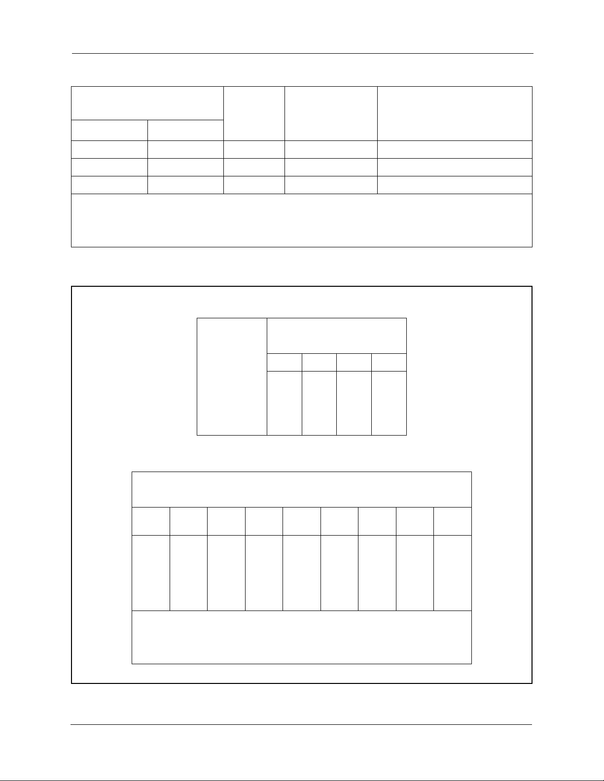
Figure 1. Slot usage for two-cabinet systems, DBS 40 + DBS 824
DBS 824 (Slave
Built-In TRK Ports 9-12
Built-In EXT Ports 25-32
208 208 CPC AUX
TRK 13-14
DBS 40 (Master)
TRK1 EC1 EC2 EC3 EC/
TRK
)
EXT 33-40
TRK 15-16
EXT 41-48
MFR
SCC CPC AUX1 AUX2
CBL-S
TRK 1-8
DBS-2.3/9.2-320 DBS Manual - Revised April 2000 3
EXT 1-8
EXT 9-16
EXT 17-24
N/A
SCC-B
CPC-B
API
CBL-M

Guidelines Section 320 - DBS 824 to DBS Interconnection Supplement
Figure 2. Slot usage for two-cabinet systems, DBS 72 + DBS 824
DBS 824 (Slave
)
Built-In TRK Ports 17-20
Built-In EXT Ports 49-56
208 208 CPC AUX
TRK 21-22
EXT 57-64
TRK 23-24
EXT 65-72
MFR
CBL-S
DBS 72 (Master)
TRK1TRK2TRK 3EC1 EC2 EC3 EC4 EC5 EC6 EC7 EC8 EC/
TRK
SCC CPC AUX1AUX
2
TRK 1-8
TRK 9-16
N/A
EXT 1-8
EXT 9-16
EXT 17-24
EXT 25-32
EXT 33-40
EXT 41-48
N/A
N/A
N/A
SCC-B
CPC-B
API
CBL-M
4 DBS Manual - Revised April 2000 DBS-2.3/9.2-320
Section 320 - DBS 824 to DBS Interconnection Supplement Guidelines
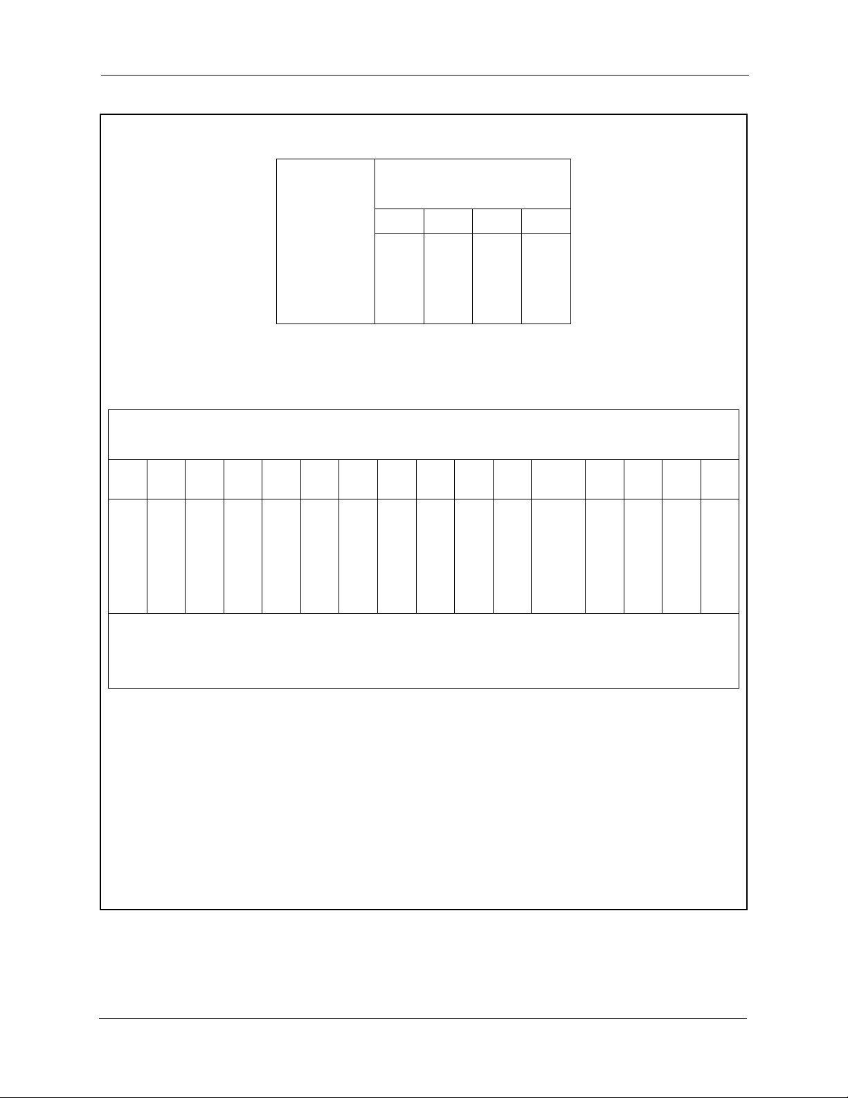
Figure 3. Slot usage for two-cabinet systems, DBS 96 + DBS 824
DBS 824 (Slave
)
Built-In TRK Ports 33-36
Built-In EXT Ports 73-80
208 208 CPC AUX
TRK 37-38
EXT 81-88
TRK 39-40
EXT 89-96
MFR
CBL-S
DBS 96 (Master)
TRK1TRK2TRK 3EC1 EC2 EC3 EC4 EC5 EC6 EC7 EC8 EC/
TRK
SCC CPC AUX 1AUX
2
TRK 1-8
TRK 9-16
TRK 17-24
EXT 1-8
EXT 9-16
EXT 17-24
EXT 25-32
EXT 33-40
EXT 41-48
EXT 49-56
EXT 57-64
TRK 25-32 or
EXT 65-72
SCC-B
CPC-B
API
Notes:
*See “T1 Interface” in Chapter 4 of the DBS Installation Manual Section 300 for EC/TRK
port numbers for a T1 installed in the DBS 96.
CBL-M
DBS-2.3/9.2-320 DBS Manual - Revised April 2000 5

Installation Section 320 - DBS 824 to DBS Interconnection Supplement
Installation
1. Set SW1 on the CBL-M card according to the following table.
Table 3. CBL-M switch settings
System
Combinations
MasterSlave 12345678
DBS 40 DBS 824 ON ON ON ON ON ON OFF ON
DBS 72 DBS 824 ON OFF ON ON ON ON OFF OFF
DBS 96 DBS 824 OFF ON OFF ON ON OFF OFF OFF
2. Install the circuit cards according to the layouts shown in the Figures 1
through 3.
Note:
3. Using the cables provided, connect the CBL-M card in the master cabinet
The port numbers for each slot are fixed.
to the CBL-S card installed in the slave cabinet. The cables should be
connected with the green ground cables located at the CBL-M card.
Note:
as shown in Figure 4 on page 7.
The EMI filter must be installed as close to the cabinet as possible,
Switch
Settings
4. Connect the green ground lead on each of the DBS cables to a side frame
screw on the DBS cabinet.
6 DBS Manual - Revised April 2000 DBS-2.3/9.2-320
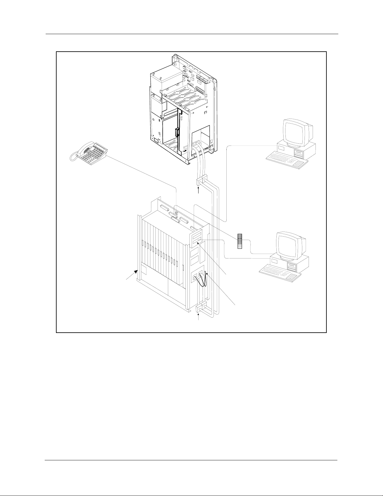
Section 320 - DBS 824 to DBS Interconnection Supplement Installation
l
Figure 4. DBS to DBS 824 cabinet installation
2
0
8
2
0
8
C
P
C
A
U
X
Slave Cabinet
RS-232C
Digital Deskset
Programming Phone
Master Cabinet
EMI
Filters
EMI
Filters
MDF
RS-232C
RS-232C
Adapter
Grounding
Wires
Programming Termina
or
SMDR Printer
SLT
Lines
PC
(VM, TSAPI, etc.)
DBS-2.3/9.2-320 DBS Manual - Revised April 2000 7

Installation Section 320 - DBS 824 to DBS Interconnection Supplement
Caution:
DO NOT connect the Red and Black wires from the CBL-S card
to the DBS 824 Power Supply. Connecting the wires may
damage the equipment.
5. If the Red and Black wires on the CBL-S card have exposed conductors,
separate the wires and cover the exposed conductors on each wire with
electrical tape.
6. Secure the Red and Black wires out of the way.
Figure 5. CBL-S Red and Black Wire Location
208 208 CPC AU X
CBL -S
Power
Supply
Power
Switch
GND
+24V
Black
Wire
Red
Wire
CAUTION:
DO NOT CONNECT THE
RED AND BLACK WIRES TO
THE DBS 824 POWER SUPPLY.
Connecting these wires may
damage the equipment.
8 DBS Manual - Revised April 2000 DBS-2.3/9.2-320
 Loading...