

nnnnn
. .
Panasonic”
x-411
WmsII
Digital Business System
Section 700
Feature
Operation
Technical Manuals Online! - http://www.tech-man.com
III
‘DOG
Issued
Part No.
rl
L
l/95
.8/
\0605Z
71
r-l
I
9DJ
I
A
FCC Warning
Warning:
cians only and is not designed for use by
warnings or cautions to advise non-technical individuals of potential dangers in
attempting to service a product. Products powered by electricity should be serviced or repaired only by experienced professional
service or repair
by anyone else could result in serious injury or death.
This service information is designed for experienced repair tecbni-
the
general public. It does not contain
the
product or products dealt with in
technicians.
this
Any attempt to
service information
This equipment generates,
uses, and can radiate radio frequency energy, and, if not installed
and used in accordance with the instruction manual, may cause interference to radio communications. This equipment has been tested and found to comply with the limits for a Class A
digital device pursuant to Part 15 of FCC Rules, which are designed to provide reasonable
protection against such interference when operated in a commercial environment. Operation
of this equipment in a residential area is likely to cause interference, in which case the user
at his own expense will be required to take necessary measures to correct the interference.
Battery Recycling Statement
The following statement applies if you purchased backup batteries with your system.
The product you have purchased contains rechargeable batteries. The batteries are recycla-
ble. At the end of their useful life, under various state and local laws, it may be illegal to dis-
pose of these batteries into the municipal waste stream.. Check with your local solid waste
officials for details on recycling options or proper disposal.
The information contained in this document is subject to change without notice and should not be
construed as a commitment by the Panasonic Communications & Systems Company (PCSC).
PCSC reserves the right, without notice; to make changes to equipment design as advances in
engineering and manufacturing methods warrant.
The software and hardware described in this document may be used or copied only in accordance
with the terms of the license pertaining to said software or hardware.
Reproduction, publication, or duplication of this manual, or any part thereof, in any manner,
mechanically, electronically, or photographically, is prohibited without permission of the
Panasonic Communications & Systems Company (PCSC).
@Copyright 1995 by Panasonic Communications & Systems Company
All rights reserved.
Technical Manuals Online! - http://www.tech-man.com
.
About This Manual
Chapter 1. List of Features
Chapter 2. System Features
Contents
Account Codes
Non-Verified Account Codes
Verified Account Codes
Answer Supervision for Voice Mail
Auto Day Mode
Auto Day
Auto Set Relocation
Background Music
Battery Backup
Call Forward ID Code for Voice Mail
Caller ID
Caller ID
Centrex/PBX
Direct Inward Dialing (DID)
DID Night Ringing Assignment
DID Delayed Ringing
DID/DNIS
DID/DNIS
DlD/DNIS
Direct Inward System Access‘(DISA)
Direct Trunk Access
Distinctive Ringing
Door
Box
Door Box (Using Trunk Adaptor)
Sensor..
DP/DTMF
DP to DTMF Signal Conversion
Hunting Priority for VAUs
Independent Timers
Internal Hold Tone
Least Cost
Music-on-Hold
Night Service
........................................................................................................................
...........................................................................................
....................................................................................................
.......................................................................................
......................................................................................................................
Mode
...............................................................................................................................
nut0
Flexible Ring Assignments
Text Name Assignment
to a Voice Mailbox
(Using Extension Adaptor)
Stations
......................................................................................................................
................................................................................................................
................................................................................................................
.....................................................................................................................
..................................................................................
DISA
Compatibility
............................................................................................................................
Routing
......................................................................................................................
........................................................................................................................
............................................................................................................
...................................................................................................
................................................................................................
.....................................................................................
.....................................................................................................
...................................................................................... 2-19
.............................................................................................
..................................................................................
.............................................................................................................
...............................................................................................................
..................................................................................
........................................................................................
...............................................................................................................
.......................................................................................... 2-29
...................................................................................................
..............................................................................................................
................................................................................................................
(LCR)
....................................................................................................
2-3
2-3
2-4
2-6
2-7
2-8
2-9
2-11
2-12
2-13
2-14
2-15
2-16
2-16
2-17
2-18
................................................................................
2-18
2-20
2-22
2-24
2-24
2-25
2-27
2-28
2-29
2-30
2-32
2-32
2-33
2-34
2-35
DBS-70-700 DBS Manual - Issued
Technical Manuals Online! - http://www.tech-man.com
8/l/95
. . .
III

Contents Section 700 - Operation
Night Service
Off-Premises Extension
Paging
Power Failure Transfer
Remote Maintenance
Station Class of Service
Station Hunting
Station Message Detail Recording (SMDR)
Tl
Telephony Services
Toll Restriction
Trunk Groups
Trunk Name Assignment
Trunk Queuing
Universal Night Answer
Voice
VAU
VAU Port Assignment
Walking TRS Class of Service
...................................................................................................................................
Remote Programming Mode
Remote Programming Using PCAS or DBS Manager
Terminal and Circular Hunting
Terminal, Distributed and Longest Idle Hunting
Interface
Mail Ringing
......................................................................................................................................
Recording
........................................................................................................................ 2-37
........................................................................................................
.........................................................................................................
............................................................................................................
........................................................................................... 2-42
...................................................
........................................................................................................ 2-45
.....................................................................................................................
.......................................................................................
............................................................
.........................................................................
...........................................................................................................................
...............................................................................................................
.....................................................................................................................
........................................................................................................................
......................................................................................................
......................................................................................................................
.......................................................................................................
..............................................................................................................
and
Playing Messages
.......................................................................................................... 2-67
...................................................................................
............................................................................................. 2-69
2-39
2-39
2-41
2-42
2-44
2-46
2-47
2-49
2-51
2,54
2-56
2-58
2-61
2-62
2-63
2-64
2-65
2-66
2-66
.
Chapter 3. Attendant Features
Alternate Attendant
Attendant Assignment of Speed Dialing
Attendant Busy Override
Attendant Call Park
Attendant Control of Absence Messages
Attendant-Controlled Text Assignment,
Attendant Feature Package
Attendant Groups
Dial Tone Disable
DSS/72
Headset Operation
Key Bank Hold
One-Touch VM Transfer
Station Lockout Code Assignment
System Time and Date Control
Traffic Measurement
Walking COS Confirmation
.................................................................................................................................. 3-13
.................................................................................................................
................................................................................
........................................................................................................
.................................................................................................................
,
............................................................................... 3-7
.................................................................................. 3-a
................................................................................................... 3-10
.................................................................................................................. 3-11
.................................................................................................................
................................................................................................................. 3-17
..................................................................................................................... 3-18
......................................................................................................
.......................................................................................
.............................................................................................
.............................................................................................................
................................................................................................. 3-25
3-3
3-3
3-4
3-5
3-12
3-18
3-21
3-22
3-24
iv
Technical Manuals Online! - http://www.tech-man.com
DBS Manual - Issued
8/l/95
DBS-70-700
Section 700 - Operation
Contents
Chapter
Key Phone
Absence Message
Auto Redial
Barge-In for Direct Lines
Busy
Override
Call
Coverage Groups..
Call
D,uration
Call
Forwarding
Call Hold
Exclusive Hold..
System Hold
Call Park
Call Pickup
Group Call Pickup
Call Transfer
Blind
Screened Transfer
Call Waiting
Call
Waiting/OHVA Text Reply
CallerIDCall Log
Camp- on
CO
Line
Conference Calls
Delayed Ringing
Dial
“0”
for Attendant
Dial Tone Disable
Do-Not-Disturb (DND)
EM/24 Console
Flexible Function (FF) Keys
Handsfree Answerback
Handsfree Operation
Headset Operation
Hot Dial Pad
Considerations
Intercom Calling
Last Number Redial
Line Appearances
DSS/BLF
Mu1
ti-CO (MCO) Appearances
Mu1
ti-Line
ML/MC0 Separation
Meet-Me Answer
Message Waiting/Callback Request
Non-Appearing Outside Lines
4.
Key Telephone Features
...............................................................................................................................
....................................................................................................................
.............................................................................................................................
........................................................................................................
......................................................................................................................... 4-7
...........................................................................................................
Display
...............................................................................................................................
...............................................................................................................................
............................................................................................................................
.........................................................................................................................
Transfer..
..........................................................................................................................
................................................................................................................................
Key
Trunk Access..
..................................................................................................................... 4-46
..........................................................................................................................
Appearances
(ML)
.............................................................................................................
....................................................................................................................
..............................................................................................................
....................................................................................................................
..........................................................................................................
...............................................................................................................
...........................................................................................................
..........................................................................................
................................................................................................................
................................................................................................
...................................................................................................................
...................................................................................................................
...........................................................................................................
.................................................................................................................
..........................................................................................................
.................................................................................................
.........................................................................................................
..............................................................................................................
.................................................................................................................
................................................................................................................
...................................................................................................................
..............................................................................................................
.................................................................................................................
.........................................................................................................
......................................................................................
Appearances..
............................................................................................................
..................................................................................................................
......................................................................................
.....................................................................................
..............................................................................................
4-3
4-3
4-6
4-6
4-8
4-9
4-10
4-16
4-
16
4-17
4-20
4-2 1
4-23
4-24
4-24
4-26
4-28
4-31
4-32
4-36
.4-37
4-38
4-41
441
4-43
4-44
4-46
4-53
4-54
4-54
4-55
4-55
4-55
4-58
4-59
4-60
4-62
4-64
4-65
4-66
4-67
4-69
DES-70-700
Technical Manuals Online! - http://www.tech-man.com
DBS Manual - issued
8/l/95
V
Contents
Offhook
Offhook
One-Touch
One-Touch VM
Onhook
Pooled
Prime Line Preference
Private Line.. .........................................................................................................................
Reminder
Ringing
Saved Number Redial
SpeedDialing
Station Lockout
Trunk-to-Trunk Transfer
Voice Mail Transfer Key
Signaling..
Voice Announce (OHVA)
Keys
Dialing
Trunk Access
C,all
Line
System Speed
Speed Dial Linking
.....................................................................................................
......................................................................................
...................................................................................................................
Access ........................................................................................................
.....................................................................................................................
............................................................................................................
..........................................................................................................
.......................................................................................................................
Preference
........................................................................................................................
Dial
.....................................................................................................................
.......................................................................................................
...........................................................................................................
..........................................................................................................
.........................................................................................................
.......................................................................................................
......................................................................................................
Section 700 - Operation
.;.
....... 4-70
4-7 1
4-73
4-77
4-80
4-80
4-82
4-83
4-84
4-86
4-86
4-87
4-91
4-93
4-95
4-96
4-97
Chapter 5. DSLT Features
DSLT ......................................................................................................................................
Absence Message
Auto Redial
Busy
Ove,ride
Call
Forwarding
Call
Hold................................................................................
Call
Park ...............................................................................................................................
Call Pickup............................................................................................................................
Direct Call Pickup
Group Call Pickup
Call
Transfer.........................................................................................................................
Blind Transfer
Screened Transfer
Call
Waiting..........................................................................................................................
Camp-on
Conference Calls..
Dial
Dial Tone Disable
Direct Trunk Access
Do-Not-Disturb (DND)
Intercom Calling
Last Number Redial
Meet-Me Answer
Message Waiting/Callback
Off-Hook Voice
................................................................................................................................
“0” for Attendant..
....................................................................................................................
.............................................................................................................................
.........................................................................................................................
......................................................................................................................
............................................. 5-l
.‘.
...........................................................................................................
..........................................................................................................
.................................................................................................................
...........................................................................................................
.................................................................................................................
.........................................................................................................
.................................................................................................................
.............................................................................................................
.........................................................................................................
...................................................................................................................
..............................................................................................................
..................................................................................................................
Request .....................................................................................
Announce (OHVA)....................................................................................
5-3
5-4
5-6
5-6
5-7
5-12
5-14
5-14
5-15
5-16
5-16
5-
17
5-19
5-21
5-22
5-23
5-24
5-24
5-25
5-26
5-27
5-28
5-29
5-30
1
Vi
DBS Manual - Issued
Technical Manuals Online! - http://www.tech-man.com
8/l/95
DBS-70-700
Section 700 - Operation Contents
Onhook Dialing..
Pooled Trunk
Reminder
Saved
CalI
Number
Speed Dialing
Personal Speed Dialing
Station Lockout
System
Speed Dial
...................................................................................................................
Access
............................................................................................................
.......................................................................................................................
Redial
...........................................................................................................
........................................................................................................................ 5-35
...................................................................................................
.....................................................................................................................
..........................................................................................................
Chapter 6. SLT Features
Absence Message
Busy
Override..
Call Forwarding
Call Hold
Call Park
Call Pickup
...............................................................................................................................
...............................................................................................................................
............................................................................................................................
Direct Call Pickup
Group Call Pickup
Call Transfer
Blind Transfer
Screened Transfer
Call Waiting
Camp-on
................................................................................................................................
Conference Calls
Dial “0” for Attendant
Dial Tone Disable
Direct Trunk Access
Do-Not-Disturb (DND)
Intercom
Calling
Last Number Redial
Meet-Me Answer
Message Waiting/Callback Request
Off-Hook Voice Announce (OHVA)
Pooled Trunk Access
Speed Dialing
Personal Speed Dialing
Station Lockout
....................................................................................................................
....................................................................................
......................................................................................................................
...........................................................................................................
..........................................................................................................
.......................................................................................................................... 6-14
.................................................................................................................
...........................................................................................................
..........................................................................................................................
...................................................................................................................
...........................................................................................................
.................................................................................................................
.............................................................................................................
.........................................................................................................
...................................................................................................................
..............................................................................................................
..................................................................................................................
.....................................................................................
....................................................................................
............................................................................................................
........................................................................................................................
...................................................................................................
.....................................................................................................................
.;.
................................ 6-5
5-32
5-32
5-33
5-34
5-35
5-37
5-38
6-3
6-6
6-10
6-11
6-12
6-12
6-13
6-14
6-15
6-17
6-19
6-20
6-21
6-22
6-23
6-23
6-25
6-26
6-27
6-28
6-29
6-30
6-31
6-3
1
6-33
DBS-70-700
Technical Manuals Online! - http://www.tech-man.com
DBS Manual - Issued
8/l/95
vii

Contents Section 700 - Operation
. . .
VIII
DBS Manual - Issued
Technical Manuals Online! - http://www.tech-man.com
8/l/95
DBS-70-700
Section 700 - Operation
About This Manual
Software Versions Covered by This Manual
This manual covers all versions of CPC-A, all versions of CPC-AII software
through Version 7.0 and CPC-B software through Version 7.0.
Differences in feature availability or operation are noted within each feature
description.
If you are using this manual for a single DBS system, make note of its
software version in the following table. This note may be referenced by
technicians or owners of the system.
Software version information for systems shipped with this
document
1
CPC Model:
I
Software Version:
Introduction
Organization
This manual contains detailed descriptions of DBS features. The feature
descriptions are organized according to the following categories:
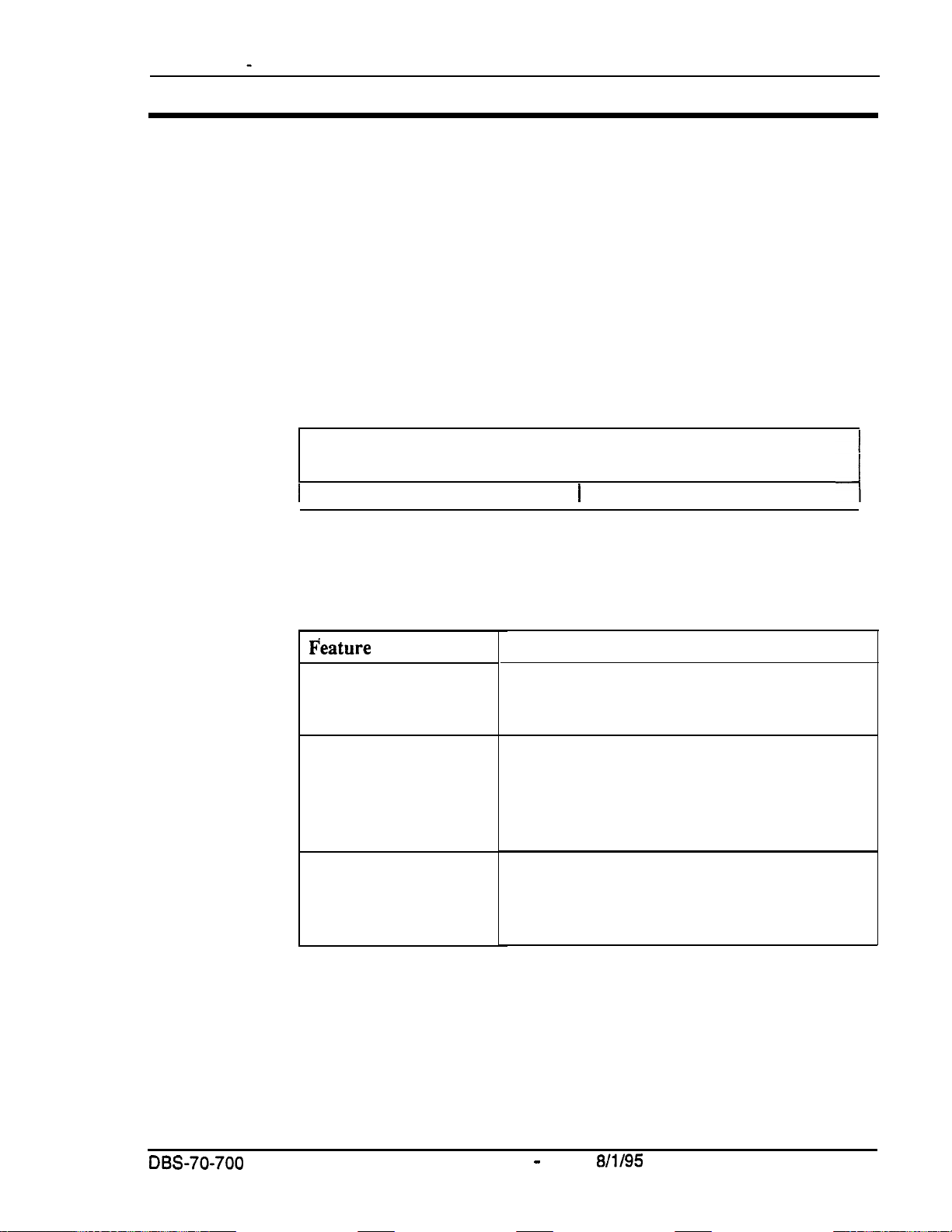
F’eature
System Features
Attendant Features
Key Telephone Features
Categories
Description
System Features are either available on a
system-wide basis or aid in the overall
administration of the DBS.
Attendant Features assist the attendant in
serving as a central answering point. In addition,
attendant features also provide special
capabilities for monitoring and programming
extensions.
Key Telephone Features are available to DBS
key phones. DBS key phones are proprietary
digital sets that provide feature access through a
combination of feature keys and access codes.
DES-70-700
Technical Manuals Online! - http://www.tech-man.com
DBS Manual
-
Issued
8/l/95
ix
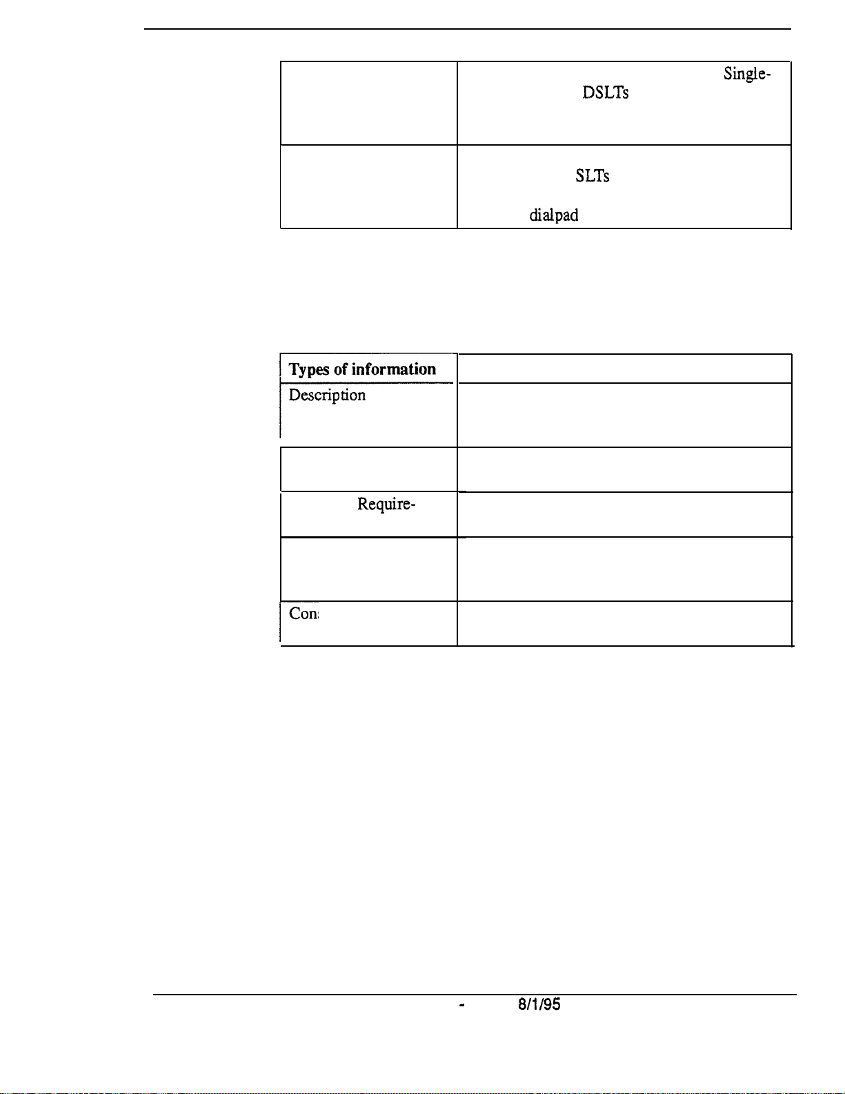
Digital Single-Line
Telephone
(DSLT) Features
DSLT Features are available to Digital
Line Telephones.
DSLTs
provide digital audio
Single-
quality and limited feature key access in a
single-line set.
Purpose
Single Line Telephone
Features
SLT Features
are available
2500 sets. Since
to industry-standard
SLTs
are not equipped with
feature keys, most features are accessed by
using the dialpad and/or the switchhook.
The purpose of this manual is to provide an overview of feature operation and
requirements. Where applicable, the following types of information are
provided for each feature.
Purpose
The Description section provides an overview
of how the feature works and, in some cases,
what it is typically used for.
Operation
The Operation section includes step-by-step
instructions on how to use the feature,
Hardware
Require-
men ts
Related Programming
This section lists any special hardware that is
required to use the feature.
The Related Programming section lists the pro-
gramming subsystems associated with the feature.
Considerations
/--
X
DBS Manual - Issued
This section provides details on feature interac-
tions and limitations.
8/l/95
DBS-70-700
Technical Manuals Online! - http://www.tech-man.com
Chapter 1. List of Features
DBS-70-700
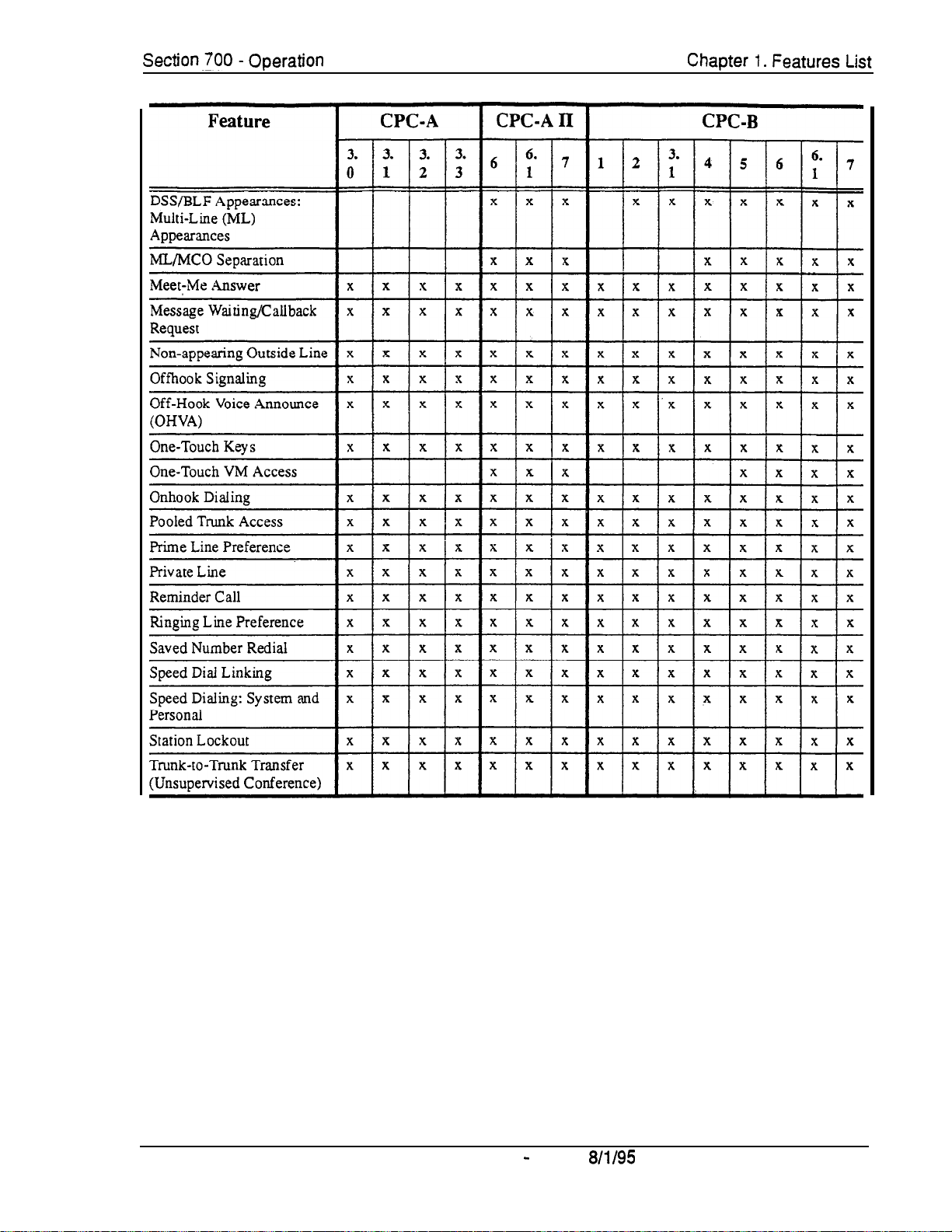
The following tables list the features available with the DBS.
The following tables are included in this chapter:
Topic Page
System Features
1
Attendant Features
1
Extension Features
I
1
l-3
l-5
l-6
1
1
DBS Manual - Issued
Technical Manuals Online! - http://www.tech-man.com
8/l/95
.
l-l

Chapter 1. Features List
Section 700 - Operation
l-2
DBS Manual - Issued
Technical Manuals Online! - http://www.tech-man.com
8/l/95
DBS-7d-700
Section 700 - Operation
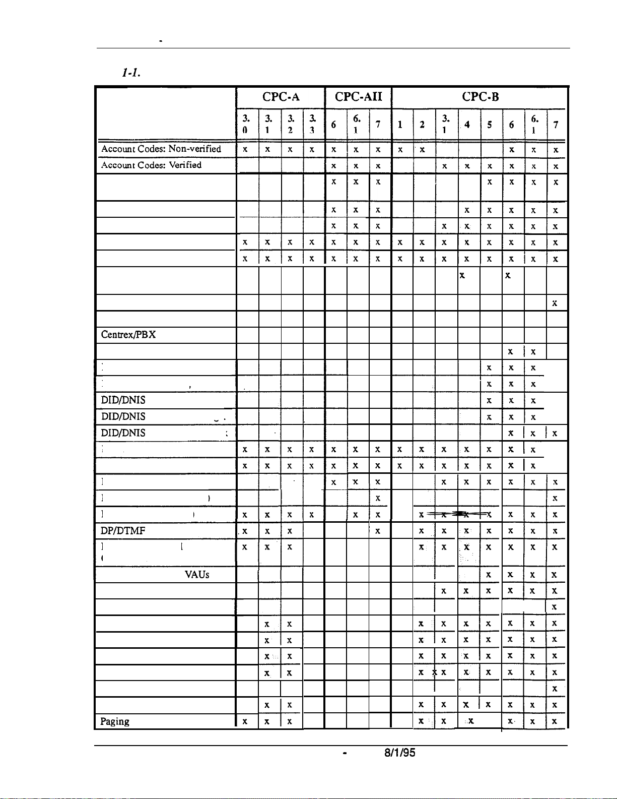
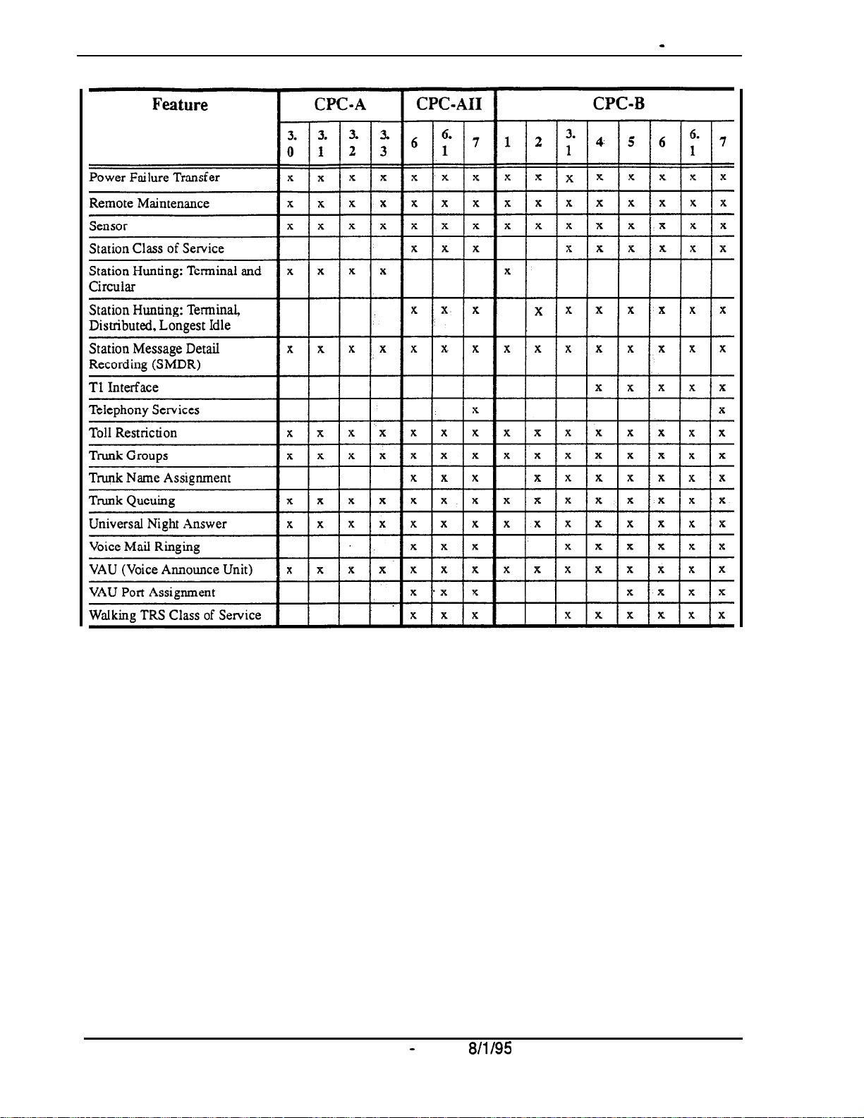
Chapter 1. Features List
Table 1
-I. System Features
~-
Feature
Answer Supervision for Voice
Mail
Auto Day Mode
Auto Set Relocation
Background Music
Battery Backup
Call Forward ID Code for
Voice Mail
Caller ID
Caller ID Auto DISA
Centrex/PBX
DID (Direct Inward Dialing)
DID Night Ringing Assignment
DID Delayed Ringing
DID/DNIS
DID/DNIS Text Name Assign.
DID/DNIS
DISA
Direct Trunk Access
Distinctive Ringing
Door Box (Extension Port)
Door Box (Trunk Port)
DP/DTMF
DP to DTMF Signal
Conversion
Hunting Priority for
Independent Timers
Internal Hold Tone
Key Bank Hold
Least Cost Routing
Music-on-Hold
Night Service
Night Service (2 Modes)
Off-Premises Extension
Compatibility
Flex. Ring Assign.
To a Voice Mailbox
Stations
VAUs
x x
x x
x x
~
X
X
X
X
+
X
+
IX
x x x x x x x.x x x x x x x
x x x x x
x x x
+
x x x
x x x
x x
x x
x x x
x x x
x x
x x
x x
x x
x x x
x x x
x x x
x x x
x x
x x
x x
x x
x x
X
x x
T
‘x
x
x x
X
X
X
x x
x x
x x
x x
X
x x
x x
x x x x x x x
x x x x
x x x
X
x x x
x x
x x
z
X
+
x x
x x
+
x x
X
x
*
x x
,x
k
Ix
x x
x x
x x
x x
8
x. x
+
x
x
x Ix
.
..x
I x
X
x x
XIX
x
x Ix
x Ix-
x Ix
x x
x x
x x x
x x x
x x x
x x x
2
I
t
t
IX
t
i
Ix
x
X
X
X
X
X
X
X
x
X
DBS-70-700
DBS Manual - issued
Technical Manuals Online! - http://www.tech-man.com
8/l/95
1-3
Chapter 1. Features List
Section 700 - Operation
l-4
DBS Manual - Issued
Technical Manuals Online! - http://www.tech-man.com
8/l/95
DBS-70-700
Section 700 - Operation Chapter 1. Features List
DBS-70-700
DBS Manual
-
Issued
8/l/95
1-5
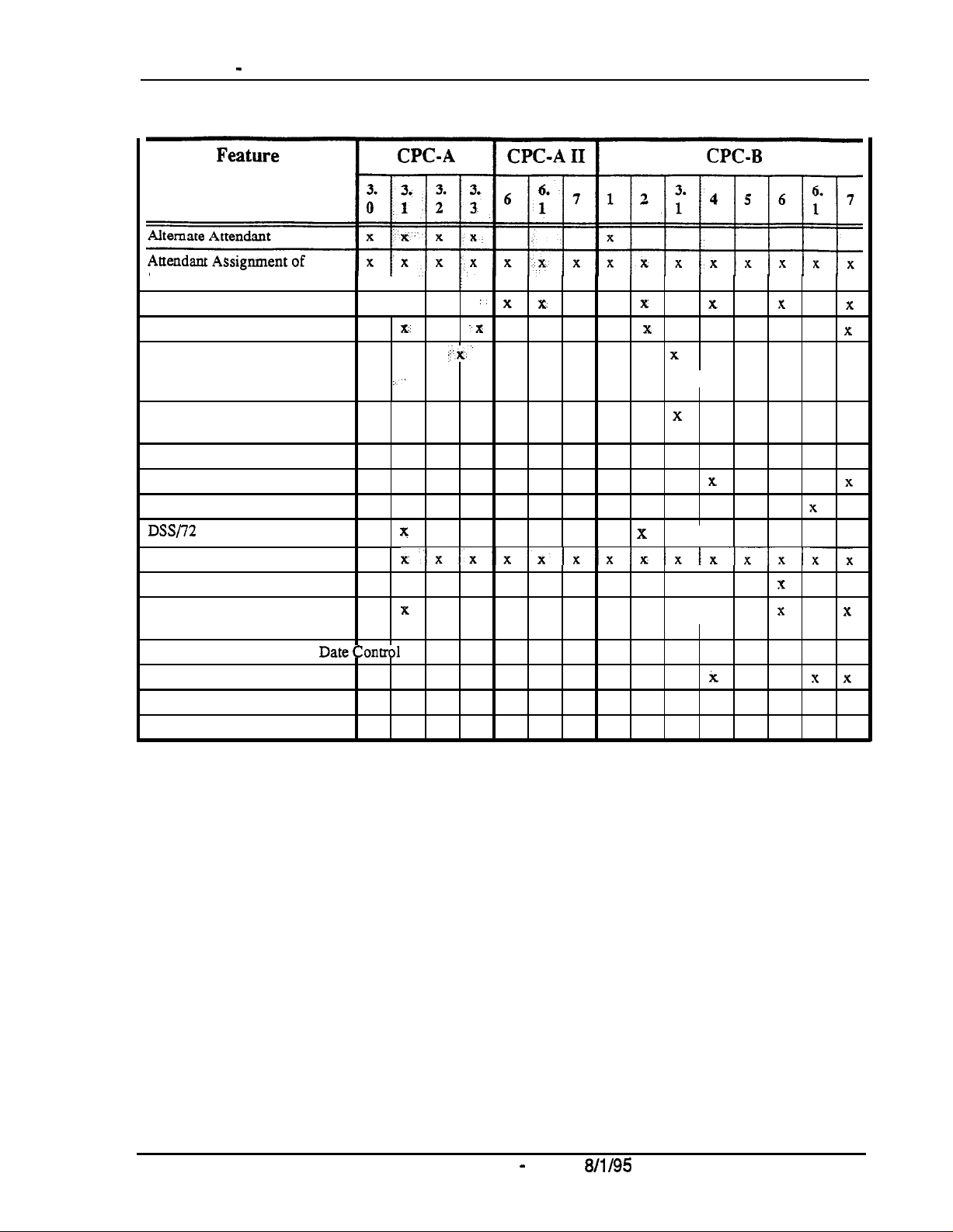
Table l-2. Attendant Features
Speed Dialing
Attendant Busy Override
Attendant Call Park
I
X
x.
x
Attendant Control of Absence x
Messages, Call Forwarding,
and DND
Attendant-Controlled Text
,:
X
.x x x x x x x x x x x x x x
Assignment
Attendant Feature Package
Attendant Groups
Dial Tone Disable
DSS/72
x x x x x x x x x x x x x x x
x & x x x x x x x x x x x x x
:. x
.x
x x x x x x x x x x
ji.x.’
x x x x x x x x x x x x x
x-
x
x
x x x x x
I
x x x
x ‘x x x x x x x x
x
x
x
Headset Operation
One-Touch VM Transfer
Station Lockout Code
Assignment
System Time and
DateConuol
Traffic Measurement
Voice Mail Transfer Key
Walking COS Confirmation
xxxxxxxxx~xxxxx
X
x x x
I
x
X
x x x x x x x x x x x x x x
x x x x x x x x x x x x x x x
x x x x x x x x x x i x x x
x x x
x x x
x x x x x x x x x
x x
x
x
Technical Manuals Online! - http://www.tech-man.com

Chapter 1. Features List Section 700 - Operation
Table l-3. Extension Features
Feature
Absence
Auto Redial
Barge-In for Direct Lines
Busy
Call Coverage Groups
Call Duration Display
Call Forwarding
Call Hold: Exclusive and
System
Call Park
Call Pickup: Direct and
Group
Call Transfer: Blind and
Screened
Call Waiting
Call
Reply
Caller ID Call Log
Camp-on
CO Line Key
Conference Calls
Delayed Ringing
Dial
Direct Trunk Access
Do-Not-Disturb (DND)
EM/24
Flexible Function
Handsfree Answerback
Handsfree Operation
Headset Operation
Hot Dial Pad
Intercom Calling
Last Number Redial
Line
DSS/BLF
Direct Line
DSS/BLF
Multi-CO (MCO)
Message
Overrid’e
WaitinglOHVA
Trunk
Access
“0”
for Attendant
Console
(FF)
Appearauces
Appearances:
(DL)
Appearances:
Text
Keys
CPC-A
CPC-A II
I
I I I IxIxlx
x x
x x x
X
x-
x
x. x
X
I
x x’x x x
x x x x x
x x x x-x
x x
x x x ‘X x x x
x x x x x x x
x x x x x x x
x x x x x x x
.x.x
.x.x
X..’
x
X
x
x x
x x
x x
x x
-t+
DBS
1-6
Manual - Issued
Technical Manuals Online! - http://www.tech-man.com
8/l/95
DBS-70-700
DBS-70-700
DBS Manual - Issued
Technical Manuals Online! - http://www.tech-man.com
8/l/95
1-7
,Chapter
2. System Features
This chapter contains detailed descriptions of DBS System Features. System
Features are either available on a system-wide basis or aid in the overall
administration of the DBS.
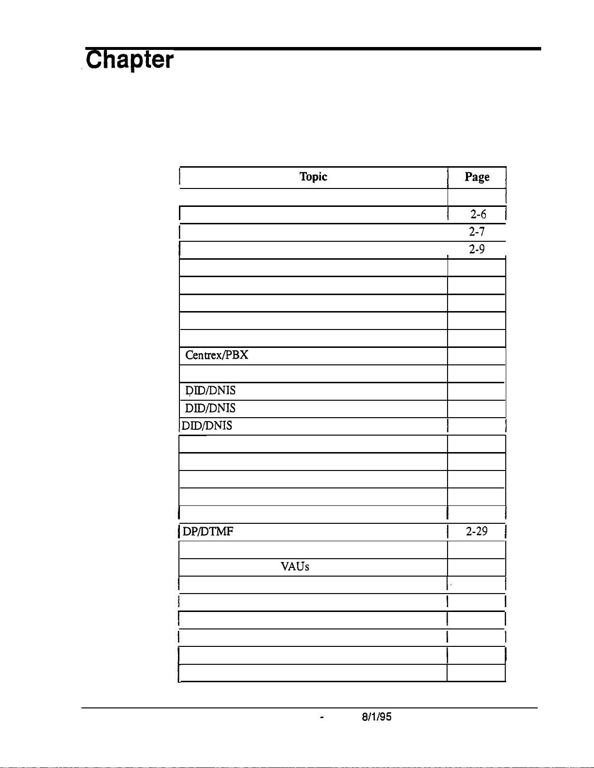
This chapter covers the following topics:
I page I
I
Account Codes
1
Answer Supervision for Voice Mail
1
Auto Day Mode
I
Auto Set Relocation
Background Music
f
I
I
I
2-3
2-6
2-7
2-g
2-11
1
1
I
I
Battery Backup
Call Forward ID Code for Voice Mail
Caller ID
Caller ID Auto DISA
Centrex/PBX
Direct Inward Dialing (DID)
DID/DNIS
DID/DNIS Text Name Assignment
I DlD/DNIS
Direct Inward System Access (DISA)
Direct Trunk Access
Distinctive Ringing
Door Box (Using Extension Adaptor)
I
Door Box (Using Trunk Adaptor)
1 DP/DTMF
DP to DTMF Signal Conversion
Compatibility
Flexible Ring Assignments
to a Voice Mailbox
Stations
2-12
2-13
2-14
2-15
2-16
2-16
2-18
2-19
1
2-20
2-22
2-24
2-24
2-25
1
2-27
1
2-29 1
2-29
1
1
Hunting Priority for
I
Independent Timers
1
Internal Hold Tone
1
Least Cost Routing (LCR)
1
Music-on-Hold
I
Night Service
Off-Premises Extension
DBS-70-700
Technical Manuals Online! - http://www.tech-man.com
VAUs
DBS Manual - Issued
8/l/95
2-30
1.
2-32
1
2-32
1
2-33
1
2-34
1
2-35
I
2-39
1
1
1
1
1
Page 2-1
Chapter 2. System Features Section 700 - Operation
Topic
Paging
Power Failure Transfe;
Page
2-39
2-41
Remote Maintenance 2-42
Station Class of Service
Station Hunting
Station Message Detail Recording (SMDR)
Tl
Interface
Telephony Services
Toll Restriction
Trunk Groups
Trunk Name Assignment
Trunk Queuing
Universal Night Answer
Voice Mail Ringing
VAU
2-45
2-46
2-51
2-54
2-56
2-58
2-61
2-62
2-63
2-64
2-65
2-66
VAU Port Assignment
Walking TRS Class of Service
2-67
2-69
Page 2-2
Technical Manuals Online! - http://www.tech-man.com
DBS Manual - Issued
8/l/95
DBS-70-700
Section 700 - Operation
Chapter 2. System Features
Account Codes
YOU
can assign account codes to clients to facilitate billing and to
dates and times, numbers called, and outside line numbers used. This
information is printed for each account on the SMDR record.
Non-Verified Account Codes
(CPC-A, CPC-AII, and CPC-B Versions prior to 3.1 and 6.0 and higher)
Description
In CPC-A and CPC-B Versions prior to 3.1, account codes are not verified.
With
CPC-AI1
be verified or non-verified depending on system programming.
and with CPC-B Versions 6.0 and higher, account codes may
track
call
Non-verified account codes can
beforced
or
voluntary,
depending on
extension programming.
With voluntary account codes, the user is not forced to enter an account
code
before making a call. With forced account codes, the user must enter an
account
code
before accessing an outside line.
Non-verified accountcodes can be assigned to incoming and outgoing calls.
To assign an account code to an outgoing call, the user enters the account
code before making the call or during the call. To assign an account code to
an incoming call, the user enters the account code during the call.
To enter an Account Code before dialing:
1.
Press the
l
The phone issues intercom dial tone.
l
The
2.
Press the
ON/OFF
ON/OFF
AUTO
key.
LED lights.
key, then press “#.”
l
“Enter Account
l
If you are using a Single Line Telephone (SLT) or Digital Single Line
##”
appears on the display.
Telephone (DSLT), dial “#7.”
3.
Enter the Account Code (up to 10 digits).
4. Press
DBS-70-700
Technical Manuals Online! - http://www.tech-man.com
“#.”
DBS Manual - Issued
8/l 195.
Page 2-3

Chapter 2. System Features
Section 700 - Operation
“Entered Account
5.
Press a vacant CO key or dial a trunk access code.
6. Dial the telephone number.
To enter an Account Code during an outside call:
1.
Press the AUTO
2. Press
“#.”
“Enter Account
3.
Enter the Account Code (up to 10 digits).
The Account Code entered appears on the display.
4. Press
Y.”
Hardware Requirements
##‘*
appears on the display.
key.
#I”
appears on the display.
l
An SMDR printer or external call accounting system is required to collect
account code records.
Related Programming
l
FF3 (Extension): Forced Account Codes
Considerations
l
SLTs
cannot assign account codes during a call.
Verified Account Codes
(CPC-AI1
Description
and CPC-B, Version 3.1 or higher)
Extensions with the Verified Account Codes feature
from making outside calls without the user first entering a valid Account
Code. After a valid Account Code is entered, the Toll Restriction Service
(TRS) type assigned to the code is substituted for the extension TRS type,
thus temporarily allowing calls based on the new TRS type.
enabled
are restricted
Page 2-4
Technical Manuals Online! - http://www.tech-man.com
DBS Manual - Issued
8/l/95
DBS-70-700

Section 700 - Operation
Chapter 2. System Features
Operation
Extensions with
the
Verified Account Codes feature
disabled
can place
outside calls based on the TRS type assigned to the extension. If a user wishes
to place a call that would normally be restricted at the extension, the user can
enter a valid Verified Account Code to upgrade the TRS type assigned to the
extension.
1.
Pick up the handset.
The phone issues intercom dial tone.
2. Dial
3.
4. Press
“#ll.”
Enter the four-digit Account Code.
“#.”
The phone issues intercom dial tone.
5.
Press an available CO key or dial a trunk access code.
The phone issues outside dial tone.
6.
Dial the telephone number.
The Verified Account Code TRS type remains in effect until the call is
completed. .
Related Programming
l
FFl
(System): Verified Forced Account Codes
l
FFl
(System): Toll Restriction for Verified Forced Account Codes
l
FF3 (Extension): Verified Forced Account Codes
l
FF7 (TRS): Toll Restrictions
Hardware Requirements
l
An SMDR printer or external call accounting system is required to collect
account code records.
Considerations
’
l
Verified account codes are for outgoing calls only.
DBS-70-700
DBS Manual - issued
Technical Manuals Online! - http://www.tech-man.com
8/l/95
Page 2-5
Chapter 2. System Features
Page 2-6
DES
Manual
-
issued
8/l/95
DBS-70-700
l
The maximum number of verified account codes is 100.
l
Each verified account code must consist of 4 digits.
l
“0000” cannot be used for a verified account code.
l
Verified account codes do not override station lockout.
l
Verified account codes do not override Least Cost Routing (LCR) settings.
l
With CPC-AlI and CPC-B Version 3.1 to 5.04, non-verified account codes
Section 700 - Operation
can be used. However, they can only be used on a voluntary basis. Forced
non-verified
account codes are not available with CPC-B 3.1 to 5.04.
Answer Supervision for Voice Mail
(CPC-AII and CPC-B Version 5.0 or higher)
Description
Operation
This feature allows the DBS to send an answer signal to third-party voice
mail systems.
In previous releases, a third-party voice mail did not receive a signal to
indicate that a DBS extension had answered. To determine that the extension
had answered, the voice mail system had to wait until it stopped receiving
ringback tone. Waiting for the ringback to stop often delayed connection
times for calls from voice mail to extensions. Sending an answer signal
provides quicker response time between the DBS and the voice mail system.
The following programming can be performed from an attendant phone or
any other phone that has entered the programming access code.
To assign an answer signal code:
1.
Press the ON/OFF key.
l
The phone issues intercom dial tone.
l
The ON/OFF LED lights.
2.
Press the PROG key.
3. Dial
‘W4.”
Technical Manuals Online! - http://www.tech-man.com

Section 700 - Operation
4.
5.
To view an answer signal code:
1.
2. Press the CONF key.
Chapter 2. System Features
Enter the Answer Signal Code (1 to 5 digits).
Press the HOLD key.
Press the ON/OFF key.
3. Dial
“#94.”
Considerations
l
The digits used for the answer signal code are determined by the
requirements of the voice mail system.
l
If the called extension does not answer and is forwarded to voice mail, the
DBS sends a call forward ID code back to the voice mail system.
l
During transmission of the answer signai code, other DTMF digits and
functions from the DBS extension are ignored.
Auto Day Mode
(Cl$-AII
Description
prior to 7.0 and CPC-B Version 4.0 to 6.11)
Auto Day Mode allows the DBS to go into day mode automatically.
The DBS can also be programmed to go into night mode automatically (see
“Night Service,” page 2-35).
If only one of the auto modes is turned on, the NIGHT key is used to turn off
the auto mode. For instance, if night mode has been activated automatically,
the attendant must press the NIGHT key to go into day mode.
If only one of the auto modes is turned on, the NIGHT key can also be used
to go into an
auto
mode before the scheduled time.
If both auto day and auto night modes are turned on, the attendant NIGHT
key cannot be used.
DBS-70-700
Technical Manuals Online! - http://www.tech-man.com
DBS Manual - Issued
8/l/95
Page 2-7
Chapter 2. System Features
Related Programming
l
FFl
(System): Automatic Day Mode Start Time
l
FFl
(System): Automatic Night Mode Start Time
Considerations
l
If both auto modes are set, the starting times must differ by at least one
hour.
l
When one auto mode is turned on, the mode cannot be reset by the
key until 3 minutes after the auto mode is activated. (When both auto
modes are set, the
l
If a
NIGHT
Section 700 - Operation
NIGHT
NIGHT
key cannot be used.)
key is not assigned, the access code #52 can be used instead.
Auto Day Mode
(CPC-B Version 7.0 or higher and CPC-A II Version 7.0 and higher)
Description
Auto Day Mode allows the DBS to go into day mode automatically.
The DBS can also be programmed to go into night mode automatically (see
“Night Service,” page 2-37).
If only one of
toggle key or the
mode. For instance, if
attendant must press the
to go into day mode. (Note: You must wait at least 3 minutes after the
automatic mode is activated before manually changing the mode. Otherwise
the system will immediately revert back to the automatic mode.)
If
only one of the
toggle key or the
an auto mode before the scheduled time. If auto day and both auto night
modes are turned on, the manual mode keys
.the
auto modes is turned on, the
DAY,
auto
DAY,
NIGHTl,
NIGHT1
DAY/NIGHTl/NIGHT2 toggle
or
NIGHT2
mode has been activated automatically, the
modes is turned on, the
NIGHTl,
or
NIGHT2
DAYMGHTUNIGHT2
is used to turn off the auto
DAYINIGHTlINIGHT2
key can also be used to go into
can
be used,
key or the
DAY
key
Related Programming
l
FFl
(System): Auto Day Mode Start Timer
l
FFl
(System): Auto Night1 Mode Start Timer
Page 2-8
Technical Manuals Online! - http://www.tech-man.com
DBS Manual - Issued
8/l/95
DBS-70-700

Section 700 - Operation
Background Music
(All Versions)
Description
If your system is set up to provide Background Music, music can be played
from the speakers of idle telephones. If a call is made to an extension
receiving Background Music, the music stops and the phone rings.
Background Music is also interrupted when the phone goes
The system can also provide music-on-hold using the Background Music
source or a separate music source. If Music-on-Hold is provided, callers
automatically hear music when they are placed
more information on Music-on-Hold.)
Operation
Chapter 2. System Features
offhook.
.on
hold. (See page 2-34 for
To turn Background Music on:
1.
Press the ON/OFF key.
l
The phone issues intercom dial tone.
l
The ON/OFF LED lights.
2. Dial
“#53.”
“BGM ON” appears on the display.
3.
Press the ON/OFF key.
The ON/OFF LED goes off.
To turn Background Music off:
1.
Press the ON/OFF key.
l
The phone issues intercom dial tone.
l
The ON/OFF LED lights.
2. Dial
“#53.”
“BGM OFF’ appears on the display.
3.
Press the ON/OFF key.
DBS-70-700
Technical Manuals Online! - http://www.tech-man.com
DBS Manual - Issued
8/l/95
Page 2-11
Chapter 2. System Features
l
The ON/OFF LED goes off.
l
The date and time appear on the display.
Related Programming
l
FFl
(System) Extension Class of Service Setting
or higher)
l
FF3 (Extension) Extension Class of Service Assignment (CPC-AlI CPC-B
3.1 or higher)
Hardware Requirements
The music source must be purchased separately. It is not provided with the
DBS.
If a single music source is used for both Music-on-Hold and Background
Music, the music source connects to the CN5 on the DBS. If a separate
music source is used for background music, it connects directly to the SCC
card. See
set the-option straps.
Installation (Section 300)
Section 700 - Operation
(CPC-AI1
for instructions. Be sure to
and CPC-B 3.1
corrrectly
The input impedance for the music source is
The maximum input level is 10
.
A
Important:
Composers, Authors, and Publishers (ASCAP) or similar organizations to
transmit radio or recorded music through the Music-On-Hold feature.
Panasonic Communications & Systems Company, its distributors, and
affiliates assume no liability should users of Panasonic equipment fail to
obtain such a license.
A license may be required from the American Society of
Battery Backup
(All Versions)
Description
The DBS two
systems use four older-style 6-volt batteries.) The backup batteries are
connected in a series circuit, using cables provided with the DBS. With
maximum traffic, the backup batteries last up to 40 minutes for the DBS
and 72, and up to 30 minutes for the DBS 96. The backup batteries should be
replaced about every 3 years.
1Zvolt
10k
ohms.
dB.
batteries for battery backup. (Some DBS 72 and 96
40
Page
2-l
2
Technical Manuals Online! - http://www.tech-man.com
DBS Manual - Issued
8/l/95
DBS-70-700

Sectron /uu -
uperatron
c;napter L. sysrem
Call Forward ID Code for Voice Mail
(CPC-A Version 3.1. CPC-AII, and all CPC-B Versions)
Descriptim
.
Call Forward ID Code for Voice Mail allows users to call forward to a
party voice mail system. The ID Code sends the digits that are required by the
voice mail to identify the DBS extension and allow it to retrieve messages.
With CPC-A or CPC-B Version 1 .O, you can only set the ID Code from the
phone to be forwarded. Beginning with CPC-B Version 2.0, ID Codes can be
set from any key phone; this is also true of CPC-AII.
Operation
To set a Call Forward ID Code for Voice Mail:
Features
third-
1.
Press the
2.
Press the
3. Press
4.
If you are using
PROG
AUTO
‘&*.”
key.
key.
CPC-AI1
extension number to be forwarded. If you are using CPC-A or CPC-B
Version 1.0, go to Step 5.
5.
Enter up to 16 digits (O-9) for the mail box ID code. (Press the
key to insert a pause.)
6.
Press the
HOLD
key.
To clear the ID Code:
1.
Press the
2.
Press the
3. Press
“*.”
PROG
AUTO
key.
key.
or CPC-B Version 2.0 or later, enter the
REDIAL
4.
Enter the extension number.
5.
Press the
DBS-70-700
Technical Manuals Online! - http://www.tech-man.com
HOLD
key.
DBS Manual - Issued
8/l/95
Page 2-13

Considerations
l
In CPC-A 3.1 and CPC-B Versions prior to 5.0, callers could hear the tones
as the ID code was transmitted to the voice mail system. Beginning with
CPC-A Version 3.3,
CPC-AI1
and CPC-B Version 5.0, external callers do
not hear the tones.
l
The Extension Copy program (FF9 2# 1 -
144#1 - 144##)
used to copy extension settings that include a Call Forward ID Code.
Copying extension settings in this manner allows the copy “destination” to
retrieve the messages of the copy “source.” For example, if you copy
extension settings
from
extension 200 to extension 300, extension 300 can
retrieve 200’s messages. Extension 300 can retrieve 200’s messages
because the Call Forward ID Code for 200 is also assigned to 300.
Caller ID
(CPC-A II Version 6.1 or higher and CPC-B Version 6.1 or higher)
Description
should not be
A properly equipped DBS supports Caller ID (CID), a service offered by the
network telephone service provider. The CO sends calling number
information to the DBS after the first ring. Users who have display telephones
can see CID information as incoming calls ring at their extension and can
have access to previous calls via the Caller ID Call Log feature. The CID
number is recorded in SMDR.
Related Programming
l
FFl (System Programming): Call Duration Display
l
FFl (System Programming): Call Duration Timer
l
FF5
(Key Assignments): FF Key Assignments for Extensions
l
FF2 (Trunk): Trunk Type
Hardware Requirements
l
Loop-start trunk card (VB-435
11A)
l
Caller ID circuit card (VB-435 11)
l
MFR card (for Caller ID Auto DISA)
Page 2-14
DBS Manual- issued
Technical Manuals Online! - http://www.tech-man.com
8/l/95
DBS-70-700
“““IIVII
*
.syv.w..*v*.
“Y
Considerations
-..- r.-’ -. -, ---... . --.-.
l
Caller ID service must be ordered from the local telephone operating
company or the interexchange carrier.
_”
Caller ID’ Auto
DISA
(CPC-A II Version 6.1 or higher and CPC-B Version 6.1 or higher)
Descfip
tion
A DBS equipped for Caller ID (CID) can provide automatic DISA dial tone
based on Caller ID information. This allows up to 10 predetermined users to
access the DISA feature without requiring a trunk be
When a CID call is sent to the DBS, the CID number is checked against the
table. If the number is found, the caller will automatically be connected to
DISA dial tone.
Related Programming
. FFl (System Programming): Automatic DISA
Hardware Requirements
left
in the DISA mode.
Considerations
DBS-70-700
l
Loop-start trunk card (VB-435 11.4)
l
Caller ID circuit card (VB-435 11)
l
MFR card (Caller ID Auto DISA)
l
Caller ID feature must be enabled.
DBS Manual - Issued
8/l/95
Page 2-15
Technical Manuals Online! - http://www.tech-man.com
Centrex/PBX Compatibility
(CPC-A Version 3.2 or higher. CPC-AII, and CPC-B Version 2.1 or higher)
Description
Centrex/PBX Compatibility allows the DBS to be connected to centrex or
PBX lines.
The DBS supports up to 8 access codes for dialing centrex or a PBX. These
access codes allow the DBS SMDR output to exclude the number dialed to
reach a centrex or PBX line.
The DBS also supports transmission of a flash signal over the centrex or PBX
link.
Related Programming
l
FFl (System): PBX Access Code(s)
l
FF2 (Trunks): Trunk Type
l
FF8 (Least Cost Routing): LCR Add Tables
Considerations
l
The LCR Add Table can be used to prefix digits for outgoing calls through
Centrex.
Direct Inward Dialing (DID)
(CPC-B Version 2.0 or higher)
Description
The Direct Inward Dialing (DID) feature allows an extension to have a
dedicated direct number. The dedicated number allows calls to be made
directly to the extension, without the caller going through the attendant.
Prior to CPC-B Version 3.1, only one DID number could be assigned to an
extension. Beginning with CPC-B Version 3.1, one DID number can be
assigned to several extensions, and one extension can have more than one
DID number; this is also true of CPC-AII.
If a DID number is assigned to more than one extension, incoming calls to the
DID number ring at all the assigned extensions simultaneously.
Page 2-16
Technical Manuals Online! - http://www.tech-man.com
DBS Manual - Issued
8/l/95
DBS-70-700
Section 700 - Operation
Related Programming
l
FFl
(System):
l
FF3
(Extension): Inbound DID Dial Number (CPC-B Version 2.0 to 2.16)
l
FF4 (Ring): DID, Delayed, Night , Delayed Night, Night 2, and Delayed
Night 2 Ring Assignments
Hardware Requirements
l
Either the T-l Card or DID trunk card is required. Each DID trunk card
provides 8 ports.
l
The DID trunk card requires an external 48V power supply. See
Installation (Section
Considerations
Chapter 2.
System
Multiple DID (CPC-B Version 3.1 or higher)
300) for instructions.
teatures
l
The DID Trunk card supports 4-digit, dial-pulse DID.
.
The Tl card supports 4-digit, dial-pulse or DTMF DID.
l
DID numbers must be between 0000 and 9999.
l
Beginning with CPC-B Version 3.1, a maximum of 500 DID/extension
settings is allowed.
DID Night Ringing Assignment
(CPC-B Version 5.0 or higher)
Description
For a description of this feature, see “DlWDNIS Flexible Ring Assignments”
on page 2- 18.
DBS-70-700
DBS Manual - Issued
Technical Manuals Online! - http://www.tech-man.com
8/l/95
Page 2-17

c;naprer L. bysrem reaIures
DID Delayed Ringing
(CPC-B Version 5.0 or higher)
Descripfioht
3ecvon Iuu - uperarlon
For a description of this feature, see
on page 2-18.
DID/DNIS
Flexible Ring Assignments
(CPC-B Version 5.0 or higher)
Description
DID/DMS Flexible Ring Assignments allow night ringing and delayed
ringing for specific
Related Programming
l
FFl (System): Delayed Ring
l
FFl (System): Central Office Delayed Ring Timer
l
FFl (System): Inbound DID Dial Numbers
DIIYDNIS
“DIDDNIS
numbers.
Flexible Ring
Assi,onments”
Considerations
Page 2-l 8
l
FFl (System): DMS Number Setting
l
Timing for DID/DMS delayed ringing is controlled by the Central Office
Delayed Ring Timer.
l
The system uses a DID Numbers Table for DID assignment.
The
DID
Numbers Table allows up to 500 DID assignments. Each assignment
consists of the DID number and an associated extension.
l
The system uses a separate DMS Numbers Table for DMS assignment.
The DMS Numbers Table allows up to 500 DMS assignments, with each
assignment consisting of the DNIS number and an associated extension.
l
When multiple extensions are assigned delayed ringing for the same DID/
DMS number, unanswered delay ringing forwards based on the extension
with the lowest port number.
For example, if port numbers
DBS Manual - Issued
125
and
126
both have delayed ringing for the
8/l/95
DBS-70-700
Technical Manuals Online! - http://www.tech-man.com

sectton IUU - uperarlon
*.= .-
b~~apiar L. 3y3te111 raaiuras
same DNIS number and both ports do not answer a delayed ringing call, the
call follows the call forwarding settings of port 125.
OS Text
(CPC-B Version 5.0 or higher)
Description
DID/DNIS
specific
Text name assignments are especially useikl when multiple DID or DNIS
lines terminate to the same extension or group. For example, a call center may
handle inquiries for three different companies. To easily identify which
customer is being called, individual DID or DNIS numbers can be assigned
for each customer, and then corresponding text names can be assigned to the
DID or
Up to 200 DID text names and 200 DNIS text names can be assigned.
Related Programming
FFl
Text Name Assignment allows the assignment of text names to
DID/DNIS
DNIS
(System): Inbound DID Dial Numbers
Name Assignment
numbers. The text name can include up to six characters.
trunks.
Considerations
FFl (System):
A
DSS/72
If text is assigned to a
all of the extensions will receive the text display.
The text display follows forwarded calls and transferred calls.
If text is not assigned to a DIDiDNIS line, the number will display.
DNIS
Number Setting
is required to assign text names to
DWDNIS
number that rings at multiple extensions,
DIIYDNIS
trunks.
DBS-70-700
Technical Manuals Online! - http://www.tech-man.com
DBS Manual - Issued
8/l/95
Page 2-19

-..-I---.
--
-a
_ .-.. --
- - I- -.--.-”
DIDIDNIS
to a Voice Mailbox
(CPC-B Version 6.0 and higher)
Description
DID/DNIS
mailbox that is not connected to a physical extension.
To implement this feature, the
the voice mail system. Once voice mail answers, the DBS sends a
Answer Code required by the voice mail system plus the final DID/DNIS
digits to the voice mail system. The
voice mail system to open with a greeting and the DID/DNIS digits specify
the appropriate mailbox.
to a voice mailbox allows DWDNIS calls to be routed to a voice
Operation
To assign a
1.
Pick up the receiver or press the ON/OFF key.
DIDIDNIS
DIDDKIS
DIDDNIS
Answer Code:
trunks must be assigned to ring at
DID/DNIS
Answer Code signals the
2. Press PROG.
3. Dial
#95.
4. Enter the
6 digits).
5. Press HOLD.
6.
Press the
The
ON/OFF
To display a
1.
Pick up the receiver or press the
2. Press CONF.
3. Dial
4.
#95.
Press the ON/OFF key.
DIDiDNIS
ON/OFF
key.
LED goes off.
DIDIDNIS
Answer code
Answer Code:
ret
ON/OFF
.
uired ‘by the voice mail system (1 to
key.
The ON/OFF LED goes off.
Page 2-20
Technical Manuals Online! - http://www.tech-man.com
DBS Manual - Issued
8/l/95
DBS-70-700

Section 700 - Operation
Chapter 2. System Features
To delete a
1.
Pick up the receiver or press the ON/OFF key.
2. Press PROG.
3. Dial
#95.
4. Press HOLD.
5.
Press the ON/OFF key.
The ON/OFF LED goes off.
Related Programming
l
FFl
(System): Number of DID/DNIS Digits to Voice Mail
l
FFl (System):
Considerations
DIDIDNIS
that are assigned as voice mail.
DID/DNIS
digit transmission. The
Answer Code:
DID/DNIS
Flexible Ringing Assignments
DID/DNIS
digits are only sent to ports
Answer code
enby. The
DIDPNIS
Answer Code can be entered from an
attendant phone or a key phone that has entered the programming access
code.
VM ports and hunt groups.
The DID/DNIS digits can be sent to a specific
voice mail port or a. voice mail hunt group.
Second hunt group.
If the DID/DNIS call rings into a hunt group that in turn
transfers the call to a second hunt group, the DID/DNIS calls are not
transmitted to the second hunt group.
Third-par@ VM.
This feature can be used third-party voice mail systems. If
the feature is used with third-party voice mail systems, the voice mail can be
connected through analog extension ports or OPX ports.
Callforward
ID.
When DID/DNIS calls are forwarded to voice
mai 1,
the Call
Forward ID Code is transmitted to the voice mail. The DID/DNIS digits are
not.
DIDIDNZS
data transmission.
The DID/DNIS digits are transmitted over the
API link using the existing API key code packet.
DBS-70-700
Technical Manuals Online! - http://www.tech-man.com
DBS Manual - Issued
8/l/95
Page 2-21

Lriapter 2. system teatures
Secnon /UO
Direct Inward System Access (DISA)
(All Versions)
Description
Direct Inward System Access (DISA) gives off-site users dial-in access to the
DBS. Users access DISA by dialing a ‘I-digit number assigned to a DISA
trunk.
For security reasons, one incoming DISA code and two outgoing DISA codes
can be assigned. If an incoming code is assigned, it must be entered as soon as
the DISA trunk answers. An outgoing code must be entered before the user
dials an outgoing call.
Operation
-
Uperation
To make a
1.
Dial the DISA trunk number.
2.
Once you hear DISA dial tone from the DBS, enter the 4-digit DISA code
(if an incoming DISA code is assigned). If the incoming DISA code is not
programmed, you can proceed to the next step.
3.
Dial the extension number.’
To make a
1.
Dial the DISA trunk number.
2.
Once you hear DISA dial tone from the DBS, enter the 4-digit DISA code
(if an incoming DISA code is assigned). If the incoming DISA code is not
programmed, you can proceed to the next step.
3.
Dial #7 plus the 4-digit Outgoing DISA Code.
Two outgoing DISA codes are assigned. Either may be used after the
DISA
call to an extension:
DISA
call to an outside number:
#7.
4.
Dial the trunk group number you want to use (81-86 or 9).
5.
Dial the desired telephone number.
Related Programming
l
FFl
(System): Direct Inward System Access (DISA) ID Code
Page 2-22
Technical Manuals Online! - http://www.tech-man.com
DBS Manual - Issued
8/l/95
DBS-70-700

Section 700 - Operation
l
FF1
l
FFl
l
FF2 (Trunk): DISA Auto Answer
l
FF2 (Trunk): DISA Start
l
FF2 (Trunk):
To program an incoming code from an attendant phone:
Chapter 2. System Features
(System): DISA Outbound Call ID Code 1
(System): DISA Outbound Call ID Code 2
Tie
DISA
End Time
In addition to the DISA ID Setting in
used to program an incoming code.
1.
Press the ON/OFF key.
l
The phone issues intercom dial tone.
l
The ON/OFF LED lights.
2.
Press the CONF key.
3. Dial
4.
“#7.”
Enter the DISA code.
5. Press the HOLD key.
6.
Press the ON/OFF key.
The ON/OFF LED goes off.
Hard ware Requirements
FFl,
the following procedure can be
l
An MFR card is required for DISA. The
DTMF tones entered via the DISA connection.
Considerations
.
DISA can be used to access extensions as well as outside numbers.
.
Once an incoming DISA code is entered, you cannot blank it out without
entering the programming mode.
l
Busy override cannot be used for a DISA line.
.
With CPC-A and CPC-I3 Versions 2.0 to 2.1, DISA calls cannot access
hunt groups.
DBS-70-700
Technical Manuals Online! - http://www.tech-man.com
DBS Manual - Issued
MFR
8/l/95
card is required to detect
Page 2-23

Chapter 2. System Features
Direct Trunk Access
(All Versions)
Description
Extensions can access a specific trunk for outgoing calls. Extensions can also
use Direct Trunk Access to test trunks or to access data trunks.
Operation
1.
Press the ON/OFF key:
l The phone issues intercom dial tone.
l The ON/OFF LED lights.
2.
Dial “88,” then enter the desired line number (01-64).
Section 700 - Operation
l The phone issues outside dial tone.
l “CO TALK #XX” (where “XX” is the line number) appears on the
display.
3. Dial the telephone number.
The number appears on the display.
4.
Complete the call and replace the handset.
Distinctive Ringing
(CPC-All
Description
and CPC-B Version 3.1 or higher)
Distinctive trunk call ringing patterns can be set up for each extension using
the Distinctive
which extension is ringing
distinctive ringing pattern is set, the extension rings based on the incoming
ring pattern assigned to the trunk.
Ringing
feature. Distinctive Ringing allows users to determine
when
several telephones are in the same area. If no
Related Programming
l FF3 (Extension): Extension Ring Pattern
Page 2-24
Technical Manuals Online! - http://www.tech-man.com
DBS Manual - Issued
8/l/95
DBS-70-700

Section 700 - Operation
Chapter 2. System Features
Hardware Requirements
l
SCC-B Version 1.2 or higher is required for this feature.
Considerations
l
One of ten ringing patterns can be selected.
l
The ringing patterns are different for key phones and
SLT/OPX
phones.
Door Box (Using Extension Adaptor)
(CPC-B Version 7.0 and higher and CPC-A II Version 7.0 and higher)
Description
Door boxes (also called door phones) and door openers work together. The
door box is an intercom that allows visitors to announce their presence from
the
office
door. The door opener enables a user to unlock the door using a
telephone. Door openers are not sold by Panasonic; they can be purchased
separately from an electronics dealer.
Operation
There are two types of door phone adaptors available for the DBS. The first
type (VB-43701) 1
Door Box- (Using Trunk Adaptof)
uti izes
a trunk connection to connect to the door box. See
for more information. The second type
(VB-437 11) utilizes a digital port extension to connect to the door box and
door opener and is described below.
To Open a Door When Talking to the Door Box:
1.
Answer the Door Box.
2.
While still connected to the call, dial:
##3
NNNN * (where NNNN is the Door Opener Access Code, if required
9999 by default)
3.
The door will unlock. Listen for the person to enter the building before
hanging up.
-
To Open the Door When Not Talking to the Door Box:
1.
Press the ON/OFF key (or pick up the handset).
DBS-70-700
Technical Manuals Online! - http://www.tech-man.com
DBS Manual - Issued
8/l/95
Page 2-25
Chapter 2. System Features
2.
While still connected to the call, dial:
#3 XXX NNNN * (where XXX is the Door Box extension number and
NNNN is the Door Opener Access Code, if required - 9999 by default)
3.
The door will unlock. Listen for the person to enter the building before
hanging up.
Related programming
l
FF4 (Ringing and Hunt Groups): Ringing Assignments (all)
l
FFl
(System Programming): Door Phone Assignments (all)
l
FFl
(System Programming): Door Opener ID Requirement
Section 700 - Operation
Hardware
Requirements
l
l
l
l
Considerations
l
l
l
The Door Box feature requires a Door Box Adaptor
Box (Door Phone)
(VA-43705),
and door opener. The door opener can be
(VB-43711),
Door
purchased from an electronics dealer.
One Door Box can be connected to a Door Box Adaptor.
Each Door Box Adaptor uses one digital extension port.
Up to 4 Door Boxes may be connected.
The Door Box extension cannot take part in conference calls or be
overridden.
Door Box calls cannot be call forwarded or be hunting or coverage group
members.
The Door Opener can be set to open for 2 to 12 seconds.
Page 2-26
DBS Manual - Issued
Technical Manuals Online! - http://www.tech-man.com
8/l/95
DBS-70-700

Section 700 - Operation
Chapter 2. System Features
Door Box (Using Trunk Adaptor)
(All Versions)
Description
Door Boxes (also called door phones) and door openers work together. The
door box is an intercom that allows visitors to announce their presence from
the office door. The door opener enables a user to unlock the door using a
telephone. Door openers are not sold by Panasonic: they can be purchased
separately from an electronics dealer.
There are two types of door box adaptors available for the DBS. The first type
(VB-43701) utilizes a trunk connection to connect to the door box and is
described below. The second type (VB-437 1 I) utilizes a
to connect to the door phone and door opener. See “Door Box (Using
Extension Adaptor)” on page 2-25 for more information.
Operation
distal
port extension
1.
Answer the door box. (Door Box calls ring in on a dedicated FF key.)
2.
Press “3” while connected to the door box extension.
The door opens automatically.
Related Programming
l
FF4 (Ringing and Hunt Groups): Ringing Assignments (all)
l
FF2 (Trunk Programming):
Hardware Requirements
l
The Door Box requires a Door Box Adaptor
43709,
electronics dealer.
l
Up to two Door boxes can be connected to a Door Box Adaptor and utilize
the same trunk.
l
The Door Box extension cannot take part in conference calls.
and door opener. The door opener can be purchased from an
DTMF/Pulse
Dialing for Trunks
(VB-43701),
Door Box
(VA-
l
The Door Opener can. be set to open for 15 seconds, 30 seconds, or one
minute.
Technical Manuals Online! - http://www.tech-man.com
DBS Manual -
k&d A/l/M
Pnnc?
3-37

Chaoter
_--_-
-.
2. Svstem Features
Considerations
Sensor
(All Versions)
Description
Section 700 -
l While the Door Opener is functioning, a call from another Door Box on the
Ooeration
same door box adaptor cannot be answered.
l The trunk connected to the Door Box Adaptor must be set to dial pulse.
The sensor is a device that detects when a circuit is opened or closed. Sensors
can be used to detect events such
as the opening of windows or doors. When
the sensor is tripped, a tone sounds at a designated extension. Sensors are not
sold by Panasonic; they can be purchased separately from an electronics
dealer.
Hard ware Requirements
The sensor is attached to the Door Box Adaptor (VB-43701).
Trunk lines connected to the Door Box Adaptor signal the designated
extension when the sensor is tripped.
Related Programming
l FF2 (Trunks):
l FF4 (Ring Assignments): CO Day Ring Assignments
l FF4 (Ring Assignments): CO Night Ring Assignments
Considerations
l The trunk connected to the sensor must be a dial-pulse trunk.
DTMF/Pulse
Dialing for Trunks
Technical Manuals Online! - http://www.tech-man.com

Section 700 - Operation
Chapter 2. System Features
DPIDTMF
(All Versions)
Stations
Description
The DBS allows both dial pulse and DTMF extension types.
Related Programming
l FF2 (Trunk):
DTMF/Pulse
Dialing for Trunks
Considerations
l
DP to DTMF Signal Conversion allows DTMF extensions to use either
dial pulse or DTMF trunks.
DP to DTMF Signal Conversion
(All Versions)
Description
This feature allows an extension user to switch from DP to DTMF signaling
when using a DP trunk.
For instance, if a user dials into a voice mail system using a DP trunk, the user
can switch to DTMF signaling to communicate with the voice mail system.
DTMF tones can be sent either during the call or while the call is being
dialed.
Operation
To switch from dial pulse to DTMF dialing, press
Related Programming
l
FF2 (Trunk): DTMF/Puise Dialing for ‘Trunks
Considerations
“*”
or
‘W.”
l
DTMF dialing remains in effect for the duration of the call. Pulse dialing is
restored when the handset is replaced.
Technical Manuals Online! - http://www.tech-man.com

Chapter 2. System Features
*
Once DTMF dialing is invoked, the user cannot switch back to pulse
dialing without disconnecting the call.
Section 700 - Operation
l Changing from dial pulse to DTMF is possible even if the
programmed for speed dialing.
Hunting Priority for
(CPC-AI1
Description
and CPC-B Version 5.0 or higher)
This feature allows hunting priority to be assigned to calls that overflow from
the hunt group to the VAU. If the caller hears the VAU message and then
decides to dial back into the hunt group, he or she is placed before other calls
that have just entered the hunt group queue. For an illustration of the flow of
calls, see Figure 2-l on page 2-3 1.
To further improve VAU operation, DID,
routed to the first VAU message.
to the second VAU message.)
In addition, a digital port can now
programming. In previous releases,
ports. Using the standard digital port assignment required the installer to
make the following program changes:
VAUs
(In
previous releases, these calls were routed
be.assigned
VAUs
“*”
or
“#”
key is
DISA,
and transferred calls are now
as a VAU through system
were assigned as standard digital
l The CO
l The Call Waiting Notification
(FF3 l-
l Auto Pickup had to be set to “on” (FF3
l All FF keys for the extension port had to be cleared.
Offhook
144 8#).
Signal option had to be set to “on”
Tone/OHVA
option had to be set to “off’
l-14&# 12#).
(FF3 l-144#I 7#).
The VAU assignment now eliminates the need to make these program
changes. Once a port is assigned as a VAU, the system treats that port as if
these changes have been made.
Note: Though the VAU assignment treats the VAU port as if the program
settings have been made, it does not actually change the settings. If the port is
later assigned as a standard digital port, the original program settings will still
be in effect.
Technical Manuals Online! - http://www.tech-man.com

Section 700 - Operation
Timre
2-1.
t
VAU Izuntin~
Chapter 2. System Features
orioritv
Direct
Direct
Trunk CallTrunk Call
to the Hunt Groupto the Hunt Group
Pilot NumberPilot Number
----+
----+
00
00
r
r
HuntHunt
GroupGroup
QueueQueue
00
00
00
Hunt GroupHunt Group
Related Programming
Calls that transferCalls that transfer
back into the hunt groupback into the hunt group
are placed at the topare placed at the top
of the queue.of the queue.
VAUVAU
..
l
FF3 (Extension): VAU Port Assignment
l FF3 (Extension): VAU Hunting Priority
Considerations
l
The following call types are routed to the first VAU message:
-
Trunk calls (including DID and DNIS calls)
-
Transferred trunk calls
-
Intercom calls
-
Transferred intercom calls.
All recalls are routed to the second VAU message.
Technical Manuals Online! - http://www.tech-man.com

Chapter 2. System Features
Independent Timers
(CPC-AI1
and CPC-B, Version 3.1 or higher)
Section 700 - Operation
Descri’
tion
Beginning with CPC-B Version 3.1, the DBS provides separate timers for
Call Forwarding-No Answer, CO Delayed Ring, Extension Delayed Ring,
and Hunt Group--No Answer.
The Call Forwarding-No Answer timer determines how long a call will ring
an extension before forwarding.
The CO Delayed Ring and Extension Delayed Ring timers determine how
long a call will ring an extension before ringing other extensions assigned to
delayed ringing.
The Hunt Group-No Answer timer determines how long a call will ring an
idle member of a hunt group before hunting to the next idle group member.
Related Programming
l
FFI
(System): Call Forward--No Answer Timer
l
FFI
(System): Central Office Delayed Ring Timer
l
FFI
(System): Extension Delayed Ring Timer
l
FFl
(System): Hunt Group.No Answer Timer
Internal Hold
(CPC-ALI
Description
Related Programming
Version 7.0 and higher and CPC-B Version 7.0 and higher)
If a music-on-hold sound source is unavailable, a periodic hold tone
generated in the DBS can be provided to caller.
l
FFl
(System): Internal Hold Tone
Tqne
Technical Manuals Online! - http://www.tech-man.com

Section 700 - Operation
Least Cost Routing (LCR)
(All Versions)
Description
Least cost routing (LCR) automatically selects the least expensive route
available for toll calls.
LCR is accessed by dialing “9” before placing a call.
Related Programming
Primary Program Areas:
l
FFl
(System): Least Cost Routing (LCR) Access
l
FF3 (Extension): Forced Least Cost Routing
Chapter 2. System Features
l FF8 (LCR): Time Priority Tables
l FF8
l
l
l
l
Other Program Areas:
l FF8
l FF8 (LCR): LCR Delete Tables
Considerations
l If LCR is enabled, ML and
(LCR):
LCR Trunk Group Tables
FF8 (LCR): Least Cost Routing Area Codes
FF8 (LCR): Special LCR Area Codes
FF8 (LCR): Least Cost Routing (LCR) Office Codes
FF8 (LCR): Special LCR Office Codes Tables
(LCR):
LCR Add Tables
MC0
keys can be assigned for trunk group 89.
However, the FF keys will not light.
l
If the LCR feature is deactivated, Pooled Trunk Access is selected
automatically.
l Your system can be programmed to use the LCR feature for all outgoing
calls.
Technical Manuals Online! - http://www.tech-man.com

ChaDter
2. Svstem Features
Music-on-Hold
(All Versions)
Des&p tion
The DBS can provide Music-on-Hold to parties on hold on a CO line. The
Music-on-Hold feature can also be used to play announcements or
advertisements if desired.
The system can provide Music-on-Hold using the background music source
or a separate music source. See “Background Music” on page 2-l 1 for more
information.
Section 700 -
ODeration
Beginning with
hold sound source is available, an internally generated periodic hold tone can
be supplied to calls on hold.
information,
Hardware Requirements
l The music source must be purchased separately.
DBS.
l If a single music source is used for both Music-on-Hold and background
music, the music source connects to the
music source is used for background music, it is connected directly to the
SCC
card.
See Installation (Section 300)
option
l The input impedance for the music source is
l The maximum input level is 10
straps.are
CPC-AII
Version 7.0 and CPC-B Version 7.0, if no
correctly set.
See“Intemal
d.B.
music-on-
Hold Tone” on page 2-32 for more
It
is not provided with the
CN5
on the DBS. Jf a separate
for instructions. Make sure the
10k
ohms.
Important: A license may be required from the American Society of
.
A
Technical Manuals Online! - http://www.tech-man.com
Composers, Authors, and Publishers (ASCAP) or similar organizations to
transmit radio or recorded music through the Music-On-Hold feature.
Panasonic Communications & Systems Company, its distributors, and
affiliates assume no liability should users of Panasonic equipment fail to
obtain such a license.

Section 700 - Operation
Chapter 2. System Features
Night
(CPC-Ail
Service
prior to Version 7.0 and CPC-B Prior to Version 7.0)
Description
The Attendant can switch the system between Day and Night Modes for
answering outside calls. It is also possible to program the system to
automatically switch between night and day modes.
(CPC-AI1
or CPC-B
Version 4.0 or higher is required for automatic day mode settings.)
While in Night Mode (generally used at night or any time when your office is
closed), incoming calls can ring at selected extensions (a night watchman’s
extension, for example), an extension connected to an answering machine. or
to a Universal Night Answer point. Universal Night Answer
(UNA)
is used to
allow calls to be picked up from any extension.
See page 2-64 for information on setting a UNA point.
See “Auto Day Mode” (page 2-6) for information on a CPC-B Version 4.0
enhancement (also available in CPC-AII) that allows automatic switching
between day and night modes.
Operation
To switch to Night Mode:
1.
Press the ON/OFF key.
l The phone issues intercom dial tone.
l The ON/OFF LED lights.
2.
Dial “#52.”
3.
Press the ON/OFF key.
l The ON/OFF LED goes off.
l “NIGHT MODE” appears on the display.
To switch to Day Mode:
1.
Press the ON/OFF key.
l The phone issues intercom dial tone.
Technical Manuals Online! - http://www.tech-man.com

Chapter 2. System Features
l The ON/OFF LED lights.
Section 700 - Operation
2. Dial
“#52.”
3. Press the ON/OFF key.
l The ON/OFF LED goes off.
l “DAY MODE” appears on the display.
Related Programming
l
FFl
(System): Ring Patterns for UNA Terminals (M, C, & B)
l FF4 (Ringing and
l FF4 (Ringing and Hunt Groups): CO Night Ring Assignment
Hardware Requirements
l Calls during Night Mode are often directed to external paging speakers or
to an external ringing device, such as a night bell. External paging and
ringing devices are not provided with the DBS; they must be purchased
separately.
Hunt
Groups): CO Day Ring Assignment
Considerations
l If
l If there are two Attendant Phones and both DSS consoles have a NIGHT
l If the system is programmed to switch between night and day modes
“#52”
is assigned to an FF key on an attendant phone, the attendant can
switch between Day and Night Modes simply by pressing the key. The FF
key lights red when the system is in night mode.
key (programmed on a FF key), both NIGHT indicators will light red
when Night Mode is
automatically, you cannot switch between modes by using
activated.
“#52.”
Technical Manuals Online! - http://www.tech-man.com

Section 700 - Operation
Night Service
(CPC-AII Version 7.0 and higher and CPC-B Version 7.0 and higher)
Description
The Attendant can switch the system between Day and two Night Modes for
answering outside calls. It is also possible to program the system to
automatically switch between night and day modes.
Chapter 2. System Features
Operation
While in a Night Mode (generally used at night or any time when your
is closed), incoming calls can ring at selected extensions (a night watchman’s
extension, for example), an extension connected to an answering machine, or
to a Universal Night Answer point. Universal Night Answer (UNA) is used to
allow calls to be picked up from any extension.
See page 2-64 for information on setting a UNA point.
See “Auto Day Mode”-(page 2-8) for information that allows automatic
switching between day and night modes.
To switch to a Night Mode:
1.
Press the
l The phone issues intercom dial tone.
l
The
Dial “#522”
2.
can be used to toggle between Day, Night1 and Night2 modes.)
ON/OFF
ON/OFF
key.
LED lights.
for Night1 mode or
YS23”
for Night 2 mode. (Note:
office
#520
Press the ON/OFF
3.
l
The
ON/OFF
l “NIGHT MODE” or “NIGHT2 MODE” appears on the display.
key.
LED goes off.
To switch to Day Mode:
1.
Press the
l The phone issues intercom dial tone.
Technical Manuals Online! - http://www.tech-man.com
ON/OFF
key.

Chapter 2. System Features
l
The
2.
Dial
“#521.”
3.
Press the
l
The
l “DAY MODE” appears on the display.
Related Programming
l
FFl
(System): Ring Patterns for UNA Terminals (M,
l FF4 (Ringing and Hunt Groups): CO Day Ring Assignments
l FF4 (Ringing and Hunt Groups): CO Night Ring Assignments
l FF4 (Ringing and Hunt Groups): CO Night2 Ring Assignments
ON/OFF
(Note:
ON/OFF
ON/OFF
LED lights.
#520
can be used to toggle between modes.)
key.
LED goes off.
Section 700 - Operation
C;&
B)
Hardware Requirements
.
Calls during a Night Mode are often indicated by external paging speakers
or an external ringing device, such as a night bell. External paging and
ringing devices are not provided with the DBS; they must be purchased
separately.
Considerations
.
Day, Night and Night 2 modes can be assigned to FF keys on an attendant
phone. The attendant can switch between Day, Night and Night 2 modes
simply by pressing the appropriate key. The FF key lights red when the
system is in the assigned mode. Alternatively a
toggle mode key can be assigned. Pressing the key toggles between modes.
When in Day mode, the FF key LED is not lit. When in NIGHT1 mode, the
LED lights red. When in NIGHT2 mode, the LED lights green.
If the same mode key is assigned on different attendant positions, each key
indicates the current mode. For instance, if a NIGHT1 key is assigned for
two attendants, both light when in
If the system is programmed to switch between night and day modes
automatically, you
“#520/#521/#522/#523.”
software.)
DAY/NIGHTl/NIGHT2
NIGHT1
can manually switch
mode.
between modes by using the
(This is different than earlier versions of
Technical Manuals Online! - http://www.tech-man.com

Section 700 - Operation
Off-Premises Extension
(All Versions)
Description
SLTs
that are located in remote locations can be connected to the DBS
through the Off-Premises Extension (OPX) Adaptor.
Off-premise phones can be connected through a direct line to the DBS or
through the central office, depending on how far they are from the main
cabinet. For specifications, see
Operation
Installation (Section 300).
Chapter 2. System Features
Feature operation for OPX extensions is the same as for local
to the DBS.
Related Programming
l
FF3 (Extension): Terminal Type
Hardware Requirements
l
One OPX Adaptor (VB-43702) is required for each OPX extension.
l
When OPX extensions are connected through the central office, an
external ringer supply may be required. Tf required, the ringing supply is
connected to the OPX Adaptor.
Considerations
l
Up to 8 OPX extensions can be connected to a system.
l
The DBS side of the OPX Adaptor is connected to a
digital
SLTs
connected
estension port.
.
Paging
(All Versions)
Description
Internal paging is accomplished through the speakers of your system’s key
phones. The Paging feature allows you to contact someone temporarily away
DBS-70-700
Technical Manuals Online! - http://www.tech-man.com
DBS Manual - issued
8/l/95.
Page 2-39

Chapter 2. System Features
Section 700 -
OpefaikTr.
Operation
from an extension, give instructions to an entire group, or Communicate
wi&
several people at once. If an external paging system is connected to your
system, pages can also be sent through its speakers.
Beginning with CPC-B Version 3.1, the Paging feature can also be
programmed to time out after sixty seconds. When a page call times out, a
busy tone is sent to the extension that initiated the page.
To use the Paging feature:
1.
Pick up the handset.
2.
Press “#,” then enter the number of the desired Paging Group (00-07).
The
EXT
LED lights.
3. Make your announcement.
4.
Replace the handset,
Related Programming
0
FFl
(System): Page Duration (CPC AII and CPC-B Version 3.1 or higher)
l
FFl
(System): External Page Interface Control for Paging Groups
l
FF3 (Extension): Extension Page Group
Hardware Requirements
l
External relays and an amplifier are required for external paging.
Considerations
l
If an external paging system has been connected to Paging Groups
pages can be made through the external speakers. Voice Paging can also be
heard over the extensions in groups 00-07.
l
An extension can belong to more than one paging group.
l
A maximum of eight Paging Groups can be assigned to a system.
00-07,
l
Only one page may be performed at a time with one exception. Pages to
group 00 always take priority. If you page group 00 while another
extension is paging group
pager receives busy and “Page Overridden” displays on the telephone.
Page 2-40
Technical Manuals Online! - http://www.tech-man.com
DBS Manual - issued
01-07,
the other page terminates. The other
8/l/95
DBS-70-700

Section 700 - Operation
l
Paging cannot be heard at busy extensions or at extensions for which the
Do Not Disturb, Call Forwarding, or Absence Message feature is activated.
l
You can answer Paging from an idle extension by dialing the Meet-Me
Answer code (“77”) during a page or if in a call, placing the call on hold
and dialing “77.”
Chapter 2. System Features
Power
Failtire
Transfer
(All Versions)
Description
This feature provides telephone service to a limited number of
power failure. The
PW.
In the event of a power failure, the power failure extensions have dial tone
directly from the CO; system features and restrictions do not apply.
Hardware Requirements
l
Power Failure Unit (VA-43703)
l
An SLT that will be connected to the PFU.
Considerations
SLTs
SLTs
are connected to the CO via a Power Failure Unit
during a
l
Up to four
l
If a call is in progress through the PFU when the power is restored, the call
SLTs
can be connected to one Power Failure Unit.
will be disconnected.
l
For added protection against power outages, backup batteries can be
installed in the DBS. Backup batteries provide full telephone service and
system features to all DBS extensions for a limited amount of time.
With maximum traffic, the backup batteries last up to 40 minutes for the
DBS 40 and 72, and up to 30 minutes for the DBS 96.
DBS-70-700 DBS Manual - Issued
Technical Manuals Online! - http://www.tech-man.com
8/l/95
Page 2-41

Chapter 2. System Features
Remote Maintenance
(All Versions)
Section 700 - Operation
Des&p
tion
The DBS can be programmed from a remote terminal or from a remote PC.
Remote programming can be accomplished using the Remote Programming
Mode or by using Panasonic’s PCAS (Personal Computer Administration
System) or DBS Manager software.
Remote Programming Mode
(All Versions)
Description
Remote Programming Mode uses a “dumb” terminal or a PC to access the
DBS. This method of remote maintenance is less sophisticated and more
difficult than using PCAS or DBS Manager.
You can enter the Remote Programming Mode through any of these three
methods:
l
By using a local PC and communications package to connect directly to
the DBS serial port
.
Operation
l
By dialing into the system through a direct DISA trunk
l
By dialing into the system.through a regular CO trunk, then requesting the
operator to enter the Remote Programming ID Code.
Terminal Programming Through a Direct Connection
When programming from a terminal connected to the RS-232C (SMDR) port,
perform the following steps:
1. Make certain the cables are configured and connected as outlined in
Section 300.
2. Make certain the DBS is in the SMDR mode by entering the following
code from the attendant port:
ON/OFF
#93
3. Enter your terminal communications program and make sure your PC’s
data communications settings match those of the DBS.
Page 2-42
Technical Manuals Online! - http://www.tech-man.com
DBS Manual - Issued
8/l/95
DBS-70-700
Section 700 - Operation
4. From your terminal communications program, type the following
Chapter 2. System Features
command:
##99xxxx
(where xxxx = the site’s password)
5. After the DBS responds, type P and then press Enter.
Follow the directions on the screen to access the desired program. (See
“Terminal Programming Commands.“)
Terminal Programming Through
Note: The DBS must be equipped with an MFR card and a
BISA
RAI
card to
terminal programming using this method.
When programming through a DISA trunk, perform the following steps:
I.
Dial into the DBS through a
2. Once you are connected, type
DISA
#69999
trunk.
from your terminal communications
program.
3. After the DBS responds with
REMT>,
type P and then press Enter.
Follow the directions on the screen to access the desired program. (See
“Terminal Programming Commands.“)
a!low
Terminal Programming Through a CO Trunk and Operator Transfer
Note: The DBS must be equipped with an MFR card and a RAI card to allow
terminal programming using this method.
When programming through a normal trunk, perform the
I. Dial into the DB S through a normal trunk.
2. Ask the operator to place you on hold and dial
#69999
remote programming.
3. After the DBS responds with
REMT>,
type P and then press Enter.
Follow the directions on the screen to access the desired program. (See
“Terminal Programming Commands.“)
folloiving
steps:
to transfer you into
DBS
ManuaT-ksued 8/l I95
Technical Manuals Online! - http://www.tech-man.com
Page 2-43
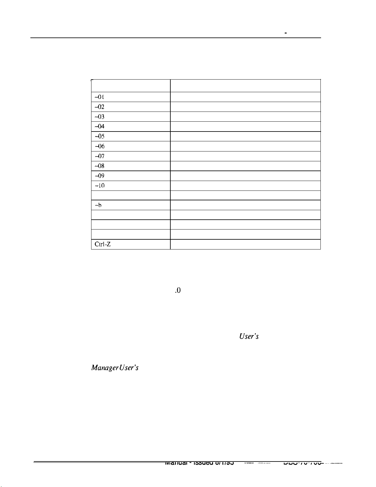
Chapter 2. System Features
..-.. ~--.-..
-.~..uBs~,o~/oo
~.~~__.
Terminal Programming Commands
Use the following commands to navigate terminal programming:
Section 700 - Operation
Command
-01
-02
-03
-04
-0s
-06
-07
48
-09
-10
-B
-b
-F
-t
-R Return IO provide mode
Crrl-Z
Description
Access System parameters
Access Trunk parameters
Access Extension parameters
Access Ring assignments
Access FF-key assignments
Access Name assignments
Access Toll Restriction data
Access Least Cost Routing data
Access Copy mode
Access Speed Dial data
Back to previous address
Back to previous port
Forward to next address
Forward to next port
Quit
Remote Programming Using PCAS or DBS Manager
(CPC-A 3.1 and higher, CPC-A II, and CPC-B 1 .O and higher)
Description
PCAS provides a menu-driven interface for remote maintenance. For
complete details about using PCAS, see the
Very similar to PCAS but more enhanced is the Windows-based program
DBS Manager. For complete details of using DBS Manager, see the DBS
Manuger tiser’s
Guide.
The primary function of these programs is to allow you to set up and maintain
DBS settings using a PC. Their communications capabilities allow you to
maintain the DBS settings while you are on-site with the DBS, or while you
are off-site at a remote location.
These programs enable you to perform tasks such as:
l Setting up communications information
PCAS
User-S
Guide.
Technical Manuals Online! - http://www.tech-man.com

Section 700 - Operation
l
Connecting
l Maintaining DBS parameters
l Backing up and restoring customer databases.
your PC with a customer’s DBS
Station Class of Service
Chapter 2. System Features
(CPC-AII
and CPC-B Version 3.1 or higher)
Description
Station Class of Service provides a way to restrict access to certain extension
features. Station Class of Service 0 provides access to all features. By default,
all extensions are assigned to this class of service. Classes of Service l-8 can
be modified to allow and restrict access to specific features. The following
table shows the features that can be enabled/disabled for station classes of
service.
Table 2-l. Station Classes of Service
Class of Service Features
Number
1
2
3
4 Absence Message Set/Reset (7 1)
5
6
7
8
9
10
11
12
13
14
15
16
17
18
19
Feature
Dial Tone On/Off
Head/Handset Exchange
BGM On/Off
Call Forward Set/Reset (72)
Do Not Disturb (73)
Station Lockout (74)
Park Hold (75)
Park Pick Up (76)
Meet Me Answer (77)
UNA Pickup (78)
Direct Pickup (79)
Group Pickup (70)
Tone/Voice Mode ( 1)
Message Waiting Set (2)
Busy Override (4)
Call Waiting (3)
Offhook
Central Office Call Queuing (2)
Voice Announce (5)
(#50)
(#IS
(#53)
1)
Technical Manuals Online! - http://www.tech-man.com

Chapter
2.
System Features
Section 700 - Operation
20
21
SLT Transfer (8)
Call Forwarding--Outside (720, 721, 722. 724) (CPC
higher)
Call Forwarding--External (723) ( CPC-A and
Note: Call forwarding -- External (723) only allows external call forwarding for
calls.
Related Programming
l
FFl
(System): Extension Class Of Service Setting
l
FF3 (Extension): Extension Class of Service Assignment
Considerations
l
Some features that are in use at the time they are disabled from the Class of
Service cannot be cancelled. For instance, if background music is turned
on at a phone at the time background music is disabled from the class of
service, the background music at the phone cannot be turned off. Make
certain that features are not
(If a feature is
class of service and turn off the feature.)
accidentially
AI1
and CPC-B Version 7.0 or
CPC-AII/CPC-B
iri
use when removed from a class of service.
Versions prior to 7.0)
internal
left active, simply reenable the feature in the
Station Hunting
(All Versions)
Station hunting allows calls to be automatically transferred among a
preselected group, of phones.
When a call terminates to a busy extension in a hunt group, the call
automatically transfers to another extension in the group. If the second
extension is busy, the call automatically transfers to another member of the
group.
Several methods of station hunting are available. The CPC version
determines which methods are available.
Technical Manuals Online! - http://www.tech-man.com
Page 2-46
DBS Manual - Issued
8/l/95
DBS-70-700

Section 700 - Operation
Terminal and Circular Hunting
(CPC-A: CPC-B Versions Prior to 2.0)
Description
CPC-A and CPC-B Versions prior to 2.0 provide terminal and circular hunt
groups.
Terminal Hunt Groups
With terminal hunt groups, a call must ring at the first extension in the group
in order for hunting to be invoked.
if the first extension of the hunt group is busy, the call automatically transfers
to the next extension in the group. If that extension is busy, the
to hunt through the group. The order in which the call hunts is determined by
how the group is programmed. Up to eight extensions can be placed in the
group, and calls will always hunt from member 1, to member 2, to member 3,
and so on.
Chapter 2. System Features
tail
continues
If desired, another hunt group can be designated to receive calls should ail the
members of the original group be busy or not answer.
A pilot number must be designated as the first extension in a terminal hunt
group. A pilot number is a fictitious extension number that, when dialed,
starts the hunting process through the group. In CPC-A and CPC-B Versions
prior to 2.0, a pilot number can be provided by adding a resistor to an analog
port. See “Hardware Requirements” for details.
Circular Hunt Groups
With circular hunting, hunting is initiated by calling any extension in the
group. If the called extension is busy, the call will hunt through the next
members of the group until the end of the hunt group is reached. If the call
reaches the end of the group without reaching an idle extension, it will
transfer back to the first member of the group until one full circle is
completed.
If desired, another hunt group can be designated to receive calls should all the
members of the original group be busy.
Related Programming
l
FF4 (Ringing and Hunt Groups): Hunt Group Member Table
l
FF4 (Ringing and Hunt Group): Call Next Hunt Group
u$STwanuat - Issuea WV93
Technical Manuals Online! - http://www.tech-man.com
rage
Z-41 -

Chapter 2, System Features
l FF4 (Ringing and Hunt Groups): Terminal/Circular Hunt Groups
l FF4 (Ringing and Hunt Groups): Ringing Assignments (all)
Hardware Requirements
l A pilot number can be provided by installing a 2 watt 450 Ohm resistor on
the analog port that will be dialed to initiate station hunting. The resistor is
placed across the tip and ring of the designated analog port.
The resistor will “busy” the port. When the busy pilot number is called, the
call will hunt through the other extensions in the group..
Considerations
Eight Station Hunt Groups can be programmed; a single Hunt Group can
contain up to eight extensions, including the pilot extension.
If all extensions in a group are busy and an alternate group has not been
designated, CO calls will queue, and intercom calls will receive busy tone.
Section 700 - Operation
If the first extension within a hunt group activates an absence message, call
forwarding, or DND, the hunt feature will not work.
If an extension other than the first extension activates an absence message,
call forwarding, or DND, the hunt feature will skip that extension, and
proceed to the next extension within the group.
The amount of time a call rings at a hunt group member before transferring
to another hunt group member is determined by the Call Forward--No
Answer Timer.
An SLT hunt group member that places a call on hold and then replaces the
handset will not receive additional hunt group calls until the held
call
is
released.
An extension that is a member of a hunt group cannot be a member of
another hunt group or a member of call coverage group.
The
offhook
signaling option should be removed from members in a hunt
group.
Technical Manuals Online! - http://www.tech-man.com

Section 700 - Operation
Chapter 2. System Features
Terminal, Distributed and Longest Idle Hunting
(CPC-AI1
and CPC-B Version 2.0 or higher)
Beginning with CPC-B Version 2.0, three types of hunt groups are available:
Terminal, Distributed, and Longest Idle. In addition,
Version 2.0 and higher also provide a software-defined pilot extension
number. The software-defined pilot number eliminates the need for the 2 W
450 Ohm resistor required for a pilot number in CPC-A and CPC-B Versions
prior to 2.0.
CPC-AI1
and CPC-B Versions 2.0 or higher also allow calls from busy hunt‘
groups to overflow to a transfer extension. The transfer extension can be the
pilot of another hunt group, the pilot (0) of the attendant group, or a single
extension number.
Terminal Hunt Groups
When the Terminal method is selected, a call to the pilot number will
repeatedly search hunt group members until the Transfer Timer expires. If
none of the members is free when the timer expires, the call is transferred to
the transfer extension.
Distributed Hunt Groups .
CPC-Al1
and CPC-B
*
When the Distributed method is selected, calls are distributed through the
pilot number based on which extension in the group received a call in the last
search. The incoming call begins its search at the next available extension in
the group and then repeatedly searches the group, in sequence, until the
Transfer Timer expires. If none of the members is free when the timer expires,
the call is transferred to the transfer extension.
Longest Idle Hunt Groups
With Longest Idle hunting, a call to the pilot number rings the extension in
the group that has been available the longest.
As with the other two methods, the search then continues through the Hunt
Group until the Transfer Timer expires. If a member does not become
available before the timer expires, the call is transferred to the transfer
extension.
An extension is not considered idle if it rings.
Related Programming
l
FF4 (Ringing and Hunt Groups): Hunt Group Search Method
l
FF4 (Ringing and Hunt Groups): Pilot Extension Number
Technical Manuals Online! - http://www.tech-man.com

Chapter 2. System Features
l
FF4 (Ringing and Hunt Groups): Hunt
l
FF4 (Ringing and Hunt Groups): Hunt Group Extension Number
l
FF4 (Ringing and Hunt Groups): Transfer Extension Number
l
FF4 (Ringing and Hunt Groups): CO Delayed Day Ring Assignments for
Hunt Group Pilot Numbers
l
FF4 (Ringing and Hunt Groups): CO Delayed Night Ring Assignments for
Hunt Group Pilot Numbers
l
FF4 (Ringing and Hunt Groups): Central Office Day Ring Assignment for
Hunt Group Pilot Numbers
l
FF4 (Ringing and Hunt Groups): Central Office Night Ring Assignment
for Hunt Group Pilot Numbers
l
FF4 (Ringing and Hunt Groups): Ringing Assignments (all)
l
FFl
Version 3.1 or higher)
.Group
(System): Hunt Group No Answer Timer
Section 700 - Operation
Transfer Timer
(CPC-AI1
and CPC-B
Considerations
l
l
l
l
l
Eight Station Hunt Groups can be programmed. A single Hunt Group can
contain up to sixteen extensions (CPC-AII and CPC-B Version 6.0 or
higher) or eight extensions (CPC-B Version 2.0 to 5.04) plus a pilot
extension number.
The transfer destination of any Hunt Group can be set to the pilot number
of the next group, the pilot number (0) of the Attendant Group, the pilot
number of the same group, or a real extension. The transfer destination
cannot be voice mail.
A Transfer Timer adjusts the transfer time between hunt groups. The
transfer time can be set from 0 to 32 seconds. If the timer is set to 0
seconds, CO calls will be queued at the hunt group until a member is
available. Intercom calls will also queue.
Central office trunks can be set to terminate to different hunt group pilot
numbers during day and night mode operation.
With CPC-AII and beginning with CPC-B 3.1, the Hunt Group No Answer
Timer determines how long a hunt group member rings before the call is
transferred to the next hunt group member. In previous releases, this time
was determined by the Call Forwarding--No Answer Timer.
l
With CPC-AI1 and beginning with CPC-B Version 4.0, a call arriving at
the the pilot number of a hunt group will hunt to a member that has call
Technical Manuals Online! - http://www.tech-man.com
Section 700 - Operation Chapter 2. System Features
forwarding set, unless call forwarding is set to an outside number. In
previous versions, hunting would skip an extension with call forwarding
set. The following call types will hunt to a member that has call forwarding
set:
-
Intercom calls
-
Transferred intercom
-
Incoming CO calls (including DID calls)
-
Transferred CO calls
-
DISA calls
cal
Is
Station Message Detail Recording (SMDR)
(All
Versions)
Description
Station Message
outgoing calls. SMDR records can be output to a printer or an external
accounting system.
Figure 2-2 shows the SMDR format for
higher. Figure 2-3 shows the SMDR format for CPC-A and CPC-B Versions
prior to 3.1.
DetaiLRecording
(SMDR) provides detailed call records of
call
CPC-AI1
and CPC-B Version 3.1 or
Technical Manuals Online! - http://www.tech-man.com
___-___-..
Page 2-51
--
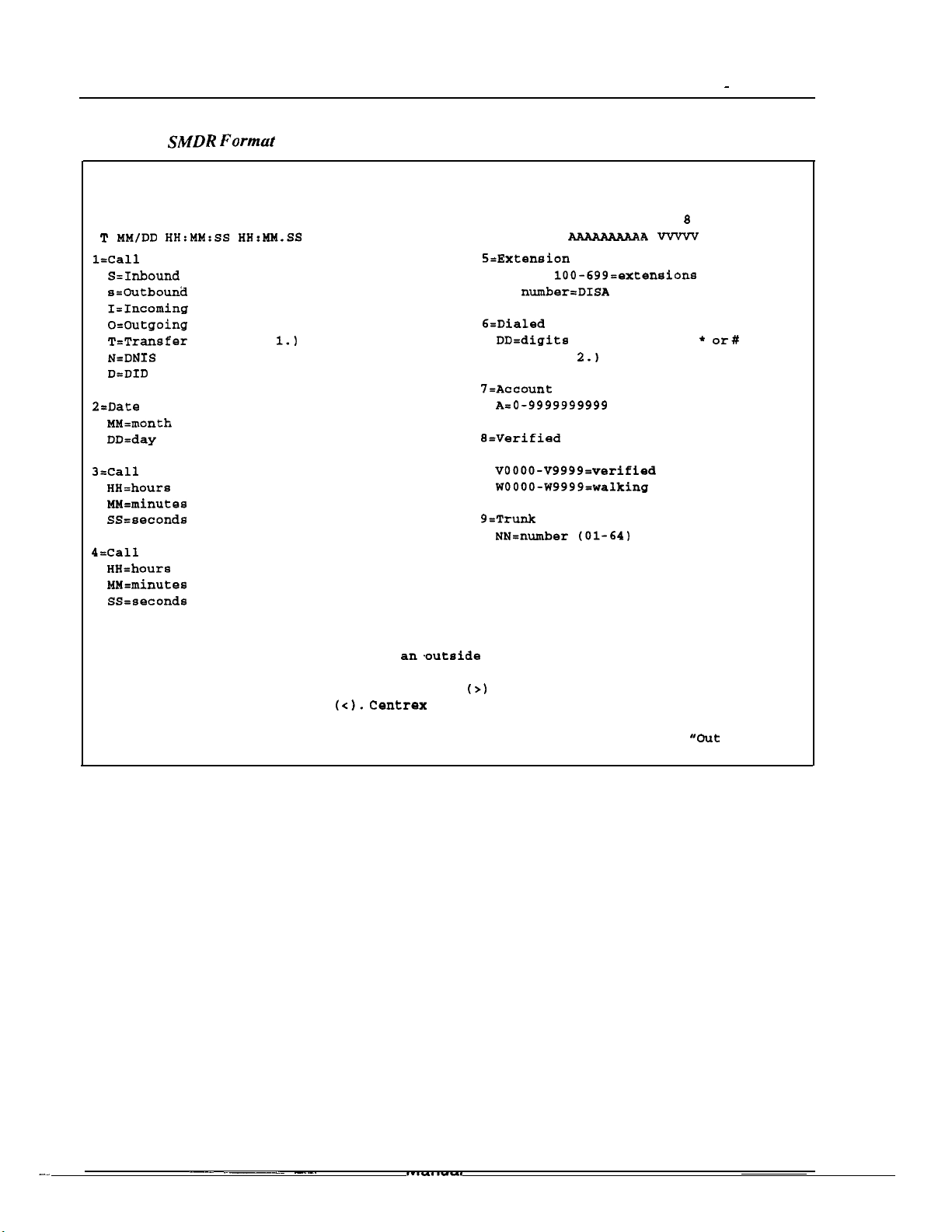
Chapter 2. System Features
-_
--- .~~--
-..-.
Section 700 - Operation
Figure 2-2.
0
01234567890123456789012345678901234567~901234567~9012345679901234567
1
T MM/DD
l=Call
S=Inbound DISA
s=Outbound DISA
I=Incoming
o=Outgoing
T=Transfer
N=DNXS
D=DID
2=Date
MM=month
DD=day
3=Call
HH=hours
M&minutes
SS=seconds
4=Call
HH=hours
MM=minutes
SS=seconds
Notes :
1. Transferred calls include direct and group call pickups and conference calls.
If a station call is transferred to an.outside number, an SMDR record is
also created for the station that is transferred.
2. The
appears as a less-than sign
not appear as dialed digits.
"Private" appears with calls that have restricted Caller ID display and
with long distance calls that do not provide Caller ID information.
SMDR Formut
1
2
type
start time
duration
l
3
HH:NM:SS
(See Note
symbol appears as a greater-than sign
for CPC-AII and CPC-B Version 3.1 or higher
2
4
HH:MM.SS
1.1
3
5
NNN DDDDDDDDDDDDDDDDDDDDDDDDDDDD AAAAAAAAAA
(<I.
Centrex and PBX codes, as well as LCR access codes, do
If the Caller ID Feature is installed and enabled,
4
6 7
5 6
5=Extension number
10-69,
CO number=DISA
C=Dialed
DD=digits
(See Note
7I=Account
A=O-9999999999
9=Verified
COS code
VOOOO-V9999=verified account codes
WOOOO-W9999=walking COS codes
9=Trunk
NN=number (01-64)
(>I
on the SMDR printout; the # symbol
100-699=exteneions
digits or Caller ID
O-9 or symbols +
code
account code or walking
Number
2.1
7
VVWV
8
9
NN
or#
"Out
of Area"
Technical Manuals Online! - http://www.tech-man.com

Section 700 - Operation
Figure 2-3. SMDR Format for CPC-A and CPC-B Versions Prior to 3.1
Chapter 2. System Features
0
0~234567890123456789012345678901234567890123456789012345678901234567890
1
Ml4
DD
l=Date
M&month
bD=day
2=Call
H&hour
MM=minute
3=Call
&hour
MM=minutes
X=l/lOth of a minute (O-9)
4=Call
I=incoming
i=DISA
O=DISA
D=Call
1
2
HH:MM H:MM.X
start time
duration
(O-9)
condition
incoming
outgoing
longer than 10 hours
2
3 4 5
C NN
3
DDDDD-DDD-DDD-DDDD
4
6
S=Trunk
NN=number (01-64)
C=Dialed
DD=digits
7=Extension
10-73,
#01-#64=DISA
B=Account
A=digits
Note: The
greater-than sign
printout;
less-than sign
5
number
digits
(See the Note following item 8.)
lOO-699=extenaions
code
O-9 or symbols l or
7
NNNAAAAAAzlAAA
O-9 or symbols l or#
number or DISA number
l
symbol appears as a
the # symbol appears as a
6
a
numbers
(>)
on the SMDR
(<).
7
Related Programming
#
l
FFl
(System): Parity Check
l
FFl
(System): Odd/Even Parity
l FFI (System): Baud Rate
l
FFI
(System): Stop Bit Length
l
FFl
(System): Data Length
l
FFl
(System): Serial Port Flow Control (X On/ X Off)
l
FFl
(System): SMDR Display Start Timer for CO Calls
l
FFl
(System): SMDR Printing Mode 1: Outbound and Inbound
l
FFl
(System): SMDR Printing Mode 2: Long Distance and Local Calls
l
FFl
(System): SMDR Printing Mode 3: Header Title
l
FF3 (Extension) Station Message Detail Recorder (SMDR) Report
Hardware Requirements
l
A printer or external call accounting system is required to receive SMDR
data.
_
.___ ~- .-----.
.-.
___.. -.-_ ..-- ----___--
‘1183;
Manual - Issued
Technical Manuals Online! - http://www.tech-man.com
8/l/95
-
Page
2-53-

Chapter 2. System Features
Tl
Interface
(CPC-B Version 4.0 or higher)
Description
The Tl Interface is a digital trunk card that provides twenty-four 64 kbps
channels, for a total transmission rate of 1.544 Mbps. Tl lines can be leased
from local exchange carriers and long-distance carriers.
The DBS Tl Interface supports the following options:
SF or ESF Framing Formats
Either super frame (SF) or extended super frame (ESF) formats can be used
with the DBS
Section 700 - Operation
Tl.
The superframe consists of 12 frames, with each
Each frame is separated by a framing bit.
An extended super frame consists of 24 frames, double the length of the super
frame (SF) format. ESF also supports monitoring and maintenance
capabilities that are not available with the SF format.
Flexible Trunk Signaling Modes
The Tl Interface provides the following
signaling modes can be assigned on a per-channel basis:
l Loop start
l Ground start
l E&M.
Related Programming
l
FFl
(System): Tl Settings (all)
l FF2 (Trunks): Trunk Type
frame
including 193 bits.
punk
signaling modes. The
l
FF2 (Trunks): Trunk Port Class
l
FF3 (Extension): Station Port Class
Hardware Requirements
l
The following hardware is required to install a Tl in a single cabinet:
Technical Manuals Online! - http://www.tech-man.com
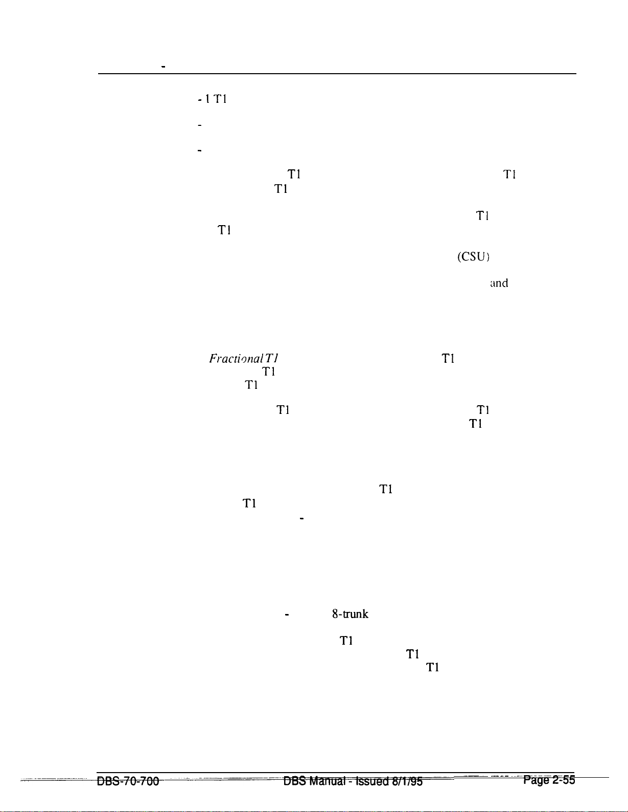
Section 700 - Operation Chapter 2. System Features
- 1 Tl
Trunk Card (VB-43561
-
1 Tl MDF Card (VB-43562)
-
1 Sync Card (VB-43563).
In addition, one Tl Cable (VB-43564) is required to install a Tl in a double
cabinet if the Tl card is located in the slave cabinet.
To install two Tls in a double cabinet, you must have 2 Tl Trunk Cards and
2 T1 MDF Cards.
Considerations
l The installer must provide a Channel Service Unit
(CSU)
that complies
with FCC Part 1.5 and Part 68. The CSU is installed between the DBS and
the public network. The CSU provides alarm, diagnostic.
:tnd
monitoring
functions. as well as network protection.
l
Fractimal Tl
can be used when fewer than 24 Tl trunks are needed.
Fractional Tl allows you to use only a portion of the 24 channels provided
on the Tl card.
l Though each
Tl
Interface provides 24 trunk channels, Tl trunks do not
increase the overall trunk capacity of the DBS. Each Tl channel subtracts
from the total number of analog trunks that can be installed. Furthermore.
the number of analog trunks that can be used may be decremented in
quantities of 1 or 8.
For instance, if you are installing a Tl in a DBS 96 and you only want to
use 12 Tl channels, the logical number of analog trunks that would be
available is 20 (32 - 12 = 20).
With CPC-B 5.00 and later, the number of analog trunks available are
decremented in quantities of 1. With CPC-B earlier than 5.00, the number
of analog trunks must be decremented in quantities of 8; the actual number
of analog trunks that can be used is 16:
(32 total trunks - 16 (two
l The current version of the
can be transmitted only if it reaches the Tl in analog form. Examples of
analog data that can be transmitted over the Tl include fax transmissions
and PC files that have been converted into analog form using a modem.
Technical Manuals Online! - http://www.tech-man.com
g-trunk
increments) = 16.j
Tl
supports voice communications only. Data
~
..---- .--..
---
rzifp2-33

Chapter
2.
System Features
Telephony Services
(CPC-AI1
Description
Version 7.0 and higher and CPC-B Version7.0 and higher)
Computer Telephony Integration (CTI) provides communication and
coordination of operation behveen computers and the telephone system. One
of the most significant emerging standards in
Appiication
Telephony Services is basically a third party call controller. Applications
designed for Telephony Services act on behalf of a group of users.
group orientation, Telephony Services provides easy operation, distribution
and transfer of calls and reporting of call handling among other features.
The DBS talks with the Telephony Server using a serial link from a specially
designed Panasonic API Card. There is no physical link between the
telephones and the networked computers. However, a logical link is
established on the Tserver to relate a telephone to a networked computer.
Programming Interface from Novell@.
Section 700 - Operation
CTI
is the Telephony Services
With
its
New applications are currently being developed that will work with DBS
Telephony Services. The possibilities for applications are unlimited. For
example:
-
inbound callers may be routed to the most appropriate customer
representative based on the caller’s phone number. As the call is
answered, the representative’s computer screen automatically
displays the customer’s information.
-
a computer-based phone directory may be used to not only look
up a phone number but also initiate a call. A corresponding
called party database may be automatically accessed when the
call is initiated.
-
the vast array of PBX features may be more easily utilized using
computer screen icons and prompting instead of complicated
telephone feature access codes and procedures
In
addition to general Telephony Services applications, since the DBS
Telephony Services meets a published standard, customized applications may
be developed to meet specific needs.
For more information on DBS Telephony Services, see the “DBS
Services Installation and Feature Description”
application used in conjunction with Telephony Services provides its own
user documentation.
in the DBS Section 520. Each
Teiephony
Technical Manuals Online! - http://www.tech-man.com

Section 700 - Operation
Chapter 2. System Features
Telephony
Outslde CO
Trunk Lines
4
DBS
Novell
Server
Novell Network
Serial
Communication
Line
API Port
Telephone Extensions
Related Programming
l
FFl
(System): API Port Type
l
FFl
(System): API Baud Rate
Hard ware Requirements
l
VB-43941 Telephony Services Kit. This kit includes a Panasonic API
Card, the API Serial Connector (two ports) and one 3
containing the Telephony Services DBS Driver
l A Novell 3.12 (or later), 486 (or greater) server with at least 8 megabytes
of RAM and equipped with an available serial port of at least 9600 baud
capacity (16550 UART required).
l
One customized serial cable (provided). The RS232 limits should not be
exceeded (50 feet).
__----..---.--
___-
..-- -.
Y
Technical Manuals Online! - http://www.tech-man.com
-_.-_-.--.-
l/2”
“Panadivr.”
__. -
floppy disk
.-..-
raw
_--
-

Chaoter
2.
Svstem Features
Toll Restriction
(All Versions)
Section 700 -
ODeration
Des&p
tion
Access levels, including the prohibition of long distance calls or after-hours
calls, can be assigned to specific extensions or CO lines using the Toll
Restriction feature. This minimizes non-business related calls and reduces
phone bills by only allowing long distance calls over designated lines.
The following access levels are available:
Table 2-2. Toll Restriction Types
Toil
Restriction
Characteristics
Type
0
Restriction of outbound dialing. (911 Calls allowed with
Version 6.0 only.)
Inbound ringing trunks can be-answered by or transferred to Type 0 extensions.
intercom
calls are allowed.
Group Call Pickup (intercom calls only)
1
Full restriction of outbound dialing (911 Calls allowed with
CPC-B Version 6.0 only)
CPC-AII/CPC-B
--
CPC-AIL’
Inbound trunk calls to all phones can be answered and/or transferred.
Intercom calls are allowed.
Group call pickup is allowed.
2
Local calls allowed
l-800 calls
al.lo.wed
Inbound trunk calls can be answered and transferred from a Type 2 phone.
Full restriction of international calls.
Full restriction of operator calls (old numbering plan)
Selectable restriction of operator calls (new NANP) - see Notes.
Selectable restriction of Speed dial numbers.
Selectable restriction of Nl 1 codes (see Notes for 911).
Restriction of up to 10 three-digit
office
codes (new NANP).
Restriction of up to 50 seven-digit numbers.
Inter-digit timing is set to 6 seconds.
. ..-
---__
Technical Manuals Online! - http://www.tech-man.com
Paae 2-58 -~
-.
_-.-.---
DBS Manual - issued
_... ---.--._.-
..-
8/l/95
.._-
.--- ~-.-.-
DBS-70-700
Section 700 - Operation
Chapter 2. System Features
3
Full restriction of operator calls (old dialing plan).
Selectable restriction of operator calls (new NANP).
Selectable restriction of international calls (defaulted to full restriction
ssee
Notes)
Selectable restriction of
Nil
codes (211-911) (see Notes for 91
I).
-
Selectable restriction of Speed dial numbers.
Restriction of up to 50 seven-digit numbers.
Trunk calls can be answered and transferred.
Defaulted to full restriction of area-code dialing (see Notes).
Defaulted to full restriction of office-code dialing (see Notes).
Inter-digit timing is set to 6 seconds.
4
Identical to Type 3, except that office-code dialing is allowed by default:
type 4 also allows Operator Calls (old dialing plan) (See Notes).
5
6
7
Programmable TRS Type; defaulted to no restrictions (see Notes).
Programmable TRS Type: defaulted to no restrictions (see Notes).
No restriction of outbound dialing.
Notes:
For TRS types 3-6 and the old numbering plan, operator calls are allowed if FF7 1# I# is set to
“on.” The office code tables are used to restrict all 0 plus dialing; the next two digits will also
be analyzed.
,
For TRS types 2 to 6 and the new NANP
(CPC-AWCPC-B
Version 6.0 and later). operator
access is determined by an extension-based operator access switch. TRS Types 0 and 1 are fully
restricted and TRS Type 7 is not restricted.
For TRS types 2 to 6 beginning with
CPC-AII/CPC-B
Version
6.0,9
11 is always allowed.
For TRS types 3-6, area code and office code restrictions can be changed using “Area Code
”
Table For TRS Types 3-6,
For TRS Types 3-6,” and “Special Office Code Table For TRS Types
“Office Code Table For TRS Types 3-6,” “Special Area Code Table
3-6,“explained
in Chap-
ter 8 of Programming (Section 400).
For TRS types 3-6. area and office code restrictions can be further managed using “Special
Area Code Table For TRS Types
3-6”
and “Special Office Code Table For TRS Types 3-6”
found in Chapter 8 of Programming (Section 400). Four area codes can be associated with special area code tables l-4 (one area code per table). Within each of these tables, the entire range
of valid office codes can be individually allowed or restricted. Thus, the Special Area and
Office Codes work together to provide specific toll restrictions.
Technical Manuals Online! - http://www.tech-man.com

Chapter 2. System Features
The following calling restrictions are also available:
l Station Lockout Key Code Restriction
A key code must be entered before calling out when the Station Lockout
feature is
l Account Code Restriction
An Account Code must be entered before calling out.
l Forced LCR Restriction
The LCR feature controls outside calls.
Related Programming
l
FFl
(System): Override Toll Restrictions with SSD Numbers
l FF3 (Extension) Extension Lockout Code
Section 700 - Operation
activated.
Considerations
l FF7 (Toll Restriction): Toll Restriction Settings (all)
l FF8 (LCR): Least Cost Routing
l The dialing restrictions included in this feature help prevent unauthorized
.
outgoing calls. It is possible, however, to program your system to allow
System Speed Dialing to override Toil Restrictions.
Technical Manuals Online! - http://www.tech-man.com

Section 700 - Operation
Trunk Groups
(All Versions)
Description
Trunks can be placed in trunk groups. When a trunk group is accessed, the
DBS automatically selects an open trunk from the group.
Operation
To access a trunk group, do one of the following:
l
Dial a trunk group access code before dialing the telephone number. Trunk
group access codes are 9, 8
l Press an FF key that is assigned as a pooled trunk key.
Related Programming
1,82, 83,84,85,
Chapter 2. System Features
and 86.
Considerations
l FF2 (Trunks): Pooled Trunk Access for Group “9”
l
FF2 (Trunks): Pooled Trunk Access for Groups “8 l-86”
l
Trunks can appear in more than one trunk group.
l
If Least Cost Routing is enabled. the trunk group
accesses the LCR features.
“9”
automatically
Technical Manuals Online! - http://www.tech-man.com

Chapter 2. System Features
Trunk Name Assignment
(CPC-All
Description
and
CPC-I3
Version 2.0 or higher)
You can display a name, number, or message of up to six characters on the
LCD in place of your CO trunk line number. The name will appear when a
CO call is ringing or connected.
For example, you can assign specific CO lines to different individuals or
departments. Then, when an extension rings, the individual’s name or the
department’s name will appear on the display, immediately identifying the
person for whom the call is intended.
While you are speaking on the extension, “CO TALK XXXXXX” will appear
on the LCD. (XXXXXX represents the six characters of the Trunk Name.)
While the extension is ringing,
“rNCOMING
the extension is ringing and you are speaking on the extension at the same
time, “INCOMING XXXXXX” will appear on the second line of the display.
Section 700 - Operation
XXXXXX” will appear. While
Related Programming
l
FF6
(Name and Message): Trunk Name Assignment
Considerations
l Trunk names can be assigned with a DSS.
l If a text name is assigned to a CO trunk, the trunk number does not appear
on the display.
Technical Manuals Online! - http://www.tech-man.com

Section 700 - Operation
Trunk Queuing
(All Versions)
Description
If all
outside lines in a Trunk Group are busy, the system can call you when a
line becomes free. Simply pick up the handset and dial the telephone number
when the Trunk Callback alert tone rings.
Operation
To set Trunk Queuing:
1.
Press the ON/OFF key.
2.
Press the CO line key or
dial
a trunk access code.
Chapter 2. System Features
The phone issues
3. Press
“In CO Queuing” appears on the display.
4.
Press the ON/OFF key.
5.
Wait for the Trunk Callback alert tone.
To respond to the Trunk Callback alert tone:
Pick up the handset.
l
The outside line is automatically accessed.
l
The phone issues dial tone.
l
“CO TALK #XX” (where “XX” is the line number) appears on the display.
Related Programming
busy tone.
“2.”
l
FFI (System): Extension Class of Service Setting
l
FF3 (Extension): Extension Class of Service Assignment
---
DES-
DBS-70-700
.--
--- -- ----
Manual -
Technical Manuals Online! - http://www.tech-man.com
l&u&d 8/j /~5----------.-----~~~-Z~~
Chapter 2. System Features
Considerations
l Response to the Trunk Callback alert tone must be within sixteen seconds
or Trunk Queuing will be canceled.
l If a call arrives from an outside line while the Trunk Queuing feature is
activated, Trunk Queuing will be suspended for the duration of the
incoming call.
l If you are engaged in another call on a different line for more than twenty
minutes after the desired outside line becomes available, that outside line’s
assignment to you will be canceled.
Section 700 - Operation
l The Trunk Queuing feature may
trying to make a call using the Pooled Trunk Access feature.
l Trunk Queuing can be used by all telephone types including
DSLTs.
Universal Night Answer
iAll
Versionsj
Description
During night mode, Universal
an external ringer, such as a night bell.
As an alternative to using a night bell,
external paging speakers.
Iiniversal
the extension’s
Night
Anstier
Ciahs
calls can be picked up from any extension, provided
of Service allows
Nght
also
be used if you hear a busy tone when
SLTs
Answer
WA
(UNA)
sends
incoming
can also be configured to ring
UNA
answer.
and
calls to
Operation
To answer a UNA call:
1. Pick up the handset.
The phone issues intercom dial tone.
2. Dial “78.”
-03
TALK #XX” appears on the display
number).
Technical Manuals Online! - http://www.tech-man.com
(where
“XX” = the trunk

Section 700 - Operation
Related Programming
l
FFI
(System): Extension Class of Service Setting
l
FFl
(System): Ring Patterns for UNA Terminals (M, C, & B)
l
FF3 (Extension): Extension Class of Service Assignment
l
FF4 (Ringing and Hunt Groups): CO Day Ring Assignment
l
FF4 (Ringing and Hunt Groups): CO Night Ring Assignment
Hard ware Requirements
l
An external ringing device is not provided with the DBS. It can be
purchased separately from an electronics dealer.
l
External paging speakers are not provided with the DBS; they must be
purchased separately.
Chapter 2. System Features
Considerations
l
With CPC-A and CPC-AII, extension port 73 is used to assign ringing to
an external
l
With CPC-B, extension port 145 is used to assign ringing to an external
page/UNA
page/UNA
interface.
Voice Mail Ringing
(CPC-AII and CPC-B Version 3.1 or higher)
Description
The Voice Mail Ringing feature allows calls from a DBS Automated
Attendant or from an ACD port to ring an extension with the same ring tone
as a CO trunk. The ring pattern is selected in the Extension Distinctive
Ringing program. Lf a distinctive ringing pattern is not specified, the ringing
pattern will be two seconds on/two seconds off.
interface.
Related Programming
l
FF3 (Extension): Extension Ring Pattern
DBS-70-700
Technical Manuals Online! - http://www.tech-man.com
DBS Manual - issued
8/l/95
Page 2-65
Chapter 2. System Features
VAU
(All Versions)
Description
The Voice Announce Unit (VAU) is a digital answering device that can be
connected to the DBS. It provides for the recording and playback of up to two
voice messages, along with the ability to transfer incoming calls.
When a call reaches the VAU, it plays a prerecorded voice message. The
caller is then allowed to dial a number or is automatically transferred to a
predetermined extension.
The VAU is often used to back up operators or hunt groups. Callers
overflowing from either of these positions hear a message and can then dial a
number or wait to be transferred back to the operator or hunt group.
Section 700 - Operation
The VAU can be
a menu of dialing options or transfer to an answering machine.
useci
to provide a variety of other services to callers, such as
Recording and Playing Messages
You can record the VAU messages from either an extension or a trunk.
Notes:
l
You must use a DTMF telephone to record and play VAU messages.
l
To change existing messages, record over them.
To record and play messages, complete the following steps.
1.
Do one of the following:
If...
You are recording or playing from an extension
Then. . .
Take your phone off hook.
Dial the VAU extension number. (If the intercom is set for Voice, dial 1 to change from
Voice to Tone.)
You are recording or playing from a trunk
Technical Manuals Online! - http://www.tech-man.com
Paae 2-66
DBS Manual - Issued
Dial the phone number of the VAU, or call in
and have the operator transfer you to the VAU
extension.
8/l/95
DBS-70-700
’

Section 700 - Operation
2.
Chapter 2. System Features
After the VAU answers, do one of the following:
. . .
I
If
You want to record the
first message
You want to record the
second message
You want to play the first
message
You want to
second message
Notes:
l You can enter the
your call.
l You can only record one message at a time. To record another
you must end your call and
play the
*97
Then. . .
I
Dial * 98 1
Wait for a beep. After the beep. record the
message.
Dial * 98 2
Wait for a beep. After the beep. record the
message.
Dial * 97 1
The VAU plays
Dial
“972
The VAU plays the message.
codes again to replay messages without ending
redial
the VAU.
thC
message.
I
i
message,
3.
When the operation is complete, put the phone on hook.
Considerations
l For more information on the VAU and its operation, see Section 770,
“Voice Announce Unit User Guide.”
VAU Port Assignment
(CPC-ALI
Operation
and CPC-B Version 5.0 or higher, CPC-A Version 3.3 and higher)
A digital port can now be assigned as a VAU through system programming.
In previous releases,
standard digital port assignment required the installer to make the following
program changes:
VAUs
were assigned as standard digital ports. Using the
*The
CO
DBS-70-700
Offhook
-
Signal option had to be set to “off’ (FF3
DBS
Manual--
Technical Manuals Online! - http://www.tech-man.com
issued
8/l/95
l-144/ 7#).
Page
2-67

Section 700 - Operation
Chapter 2. System Features
*The Call
*Auto Pickup had to be set tc “on” (FF3
*All
FF keys for the extension port had to be cleared.
Waiting/OHVA
option had to be set to “off.” (FF3 l-
l-144# 12#).
144# 8#).
The VAU assignment now eliminates the need to make these program
changes. Once a port is assigned as a VAU, the system treats that port as if
these changes have been made.
Note: Though the VAU assignment treats the VAU port as if the program
settings have been made, it does not actually change the settings. If the port is
later assigned as a standard digital port, the original program settings will still
be in effect.
To further improve VAU operation, the following call types are now routed to
the first VAU message:
*DID calls
l
DNIS calls
l
DISA calls
Programming
*Transferred trunk calls
*Transferred intercom calls.
In previous releases, only intercom and CO trunk calls were routed to the first
VAU message.
All recalls are routed to the second
message.
. FF3 (Extension): VAU Port Assignment
l FF3 (Extension): VAU Hunting Priority
Technical Manuals Online! - http://www.tech-man.com

Section 700 - Operation
Chapter 2. System Features
Walking TRS Class of Service
(CPC-AII
and CPC-B Version 3.1 or higher)
Description
Operation
Walking TRS Class of Service allows an extension user to “carry” his or her
toll restrictions to another phone.
Before the Walking TRS Class of Service feature can be used, a Walking
Class of Service code must be entered at your extension before using dialing
privileges at another extension.
To enter a Walking Class of Service code:
1.
Pick up the handset.
The phone issues intercom dial tone.
2. Dial
“#12.”
3..
Enter the four-digit Walking Class of Service code (0001-9999).
4. Press
5. Replace the handset.
“#.”
To use a Walking Class of Service code:
1.
Pick up the handset of an extension other than your own.
The phone issues intercom dial tone.
2. Dial
3.
4.
5. Press
6.
“#13.”
Enter your extension number.
Enter your Walking Class of Service code.
“#I.”
Enter a trunk access code
The phone issues outside dial tone.
(88Xx, 9,81-86).
7.
Dial the telephone number.
Technical Manuals Online! - http://www.tech-man.com
DBS-m-700-
--.--

Section 700 - Operation
To clear a Walking Class of Service code:
1. Pick up the handset.
Chapter 2. System Features
The Walking Class of Service remains in effect until you replace the
handset.
The phone issues intercom dial tone.
2. Dial
“#12.”
3. Enter the original Walking Class of Service code.
4. Press
“#.”
5. Replace the handset.
To confirm a Walking Class of Service code (Attendant Phone only):
1. Pick up the handset.
The
phone issues intercom dial tone.
2.
Press the CONF key.
3. Dial
4.
“#12.”
Enter the extension number.
The Walking Class of Service code for that extension appears on the
display.
Considerations
l
Walking Class of Service can be used by
l
The same Walking Class of Service code can be used on more than one
extension.
l
If an extension is locked out, the Walking Class of Service feature will
override the lockout.
l
LCR and TRS dialing privileges follow the Walking Class of Service.
l
Before entering a new walking COS code, you must first clear the existing
code.
Technical Manuals Online! - http://www.tech-man.com
KTELs, DSLTs,
and
SLTs.

Chapter 3. Attendant Features
This chapter describes features that are available to an attendant phone.
In addition to functioning as a central answering point, an attendant phone
also has special capabilities for monitoring and programming other phones.
This chapter covers the following topics:
1
Alternate Attendant
1
Attendant Assignment of Speed Dialing
Attendant Busy Override
1
Attendant Call Park
1
Attendant Control of Absence Messages,
I
Attendant-Controlled Text Assignment
1
Attendant Feature Package
I
Attendant Groups
Dial Tone Disable
Page
I
I
3-5
3-7
I
I
3-S
I
1
3-10
/
3-11
I
3-12
I
I
I
(
I
1 DSS/72
I
Headset Operation
Key Bank Hold
I
One-Touch VM Transfer
Station Lockout Code Assignment
System Time and Date Control
j
Traffic Measurement
Walking COS Confirmation
I
3-13
1
3-17
I
3-18
1
3-18
3-21
3-22
j
3-24
,
3-25
I
(
I
1
1
1
Technical Manuals Online! - http://www.tech-man.com

Technical Manuals Online! - http://www.tech-man.com

Section 700 - Operation
Alternate Attendant
(CPC-A and CPC-B Versions Prior to 2.0)
Description
The alternate attendant receives intercom calls directed to the primary
attendant if the primary attendant is busy or out of service.
In addition to receiving overflow intercom calls, the alternate attendant has
full access to attendant features.
With CPC-B 2.0 and above, the “Alternate Attendant” program is replaced by
the Second, Third, and Fourth Attendant Positions.
Considerations
Alternate Attendant Extension Number. The alternate attendant is always
extension number 11 or 101. By default, extension 11 or 101 is assigned to
port 2. To assign another port as an alternate attendant, you must assign
extension number 11 or 101 to that port
Chapter 3. Attendant Features
Attendant Assignment of Speed Dialing
(All Versions)
Description
The attendant can assign system speed dialing numbers. System speed dialing
numbers are shared by all DBS extensions.
Operation
1.
Press the
l The phone issues intercom dial tone.
l The ON/OFF LED lights.
2.
Press the PROG
“F’ appears on the display.
3. Press AUTO.
ON/OFF
key.
key.
“FA” appears on the display.
Technical Manuals Online! - http://www.tech-man.com
728s ManUal - Issued 8/1/YS

Chapter 3. Attendant Features
4.
Enter the Speed Dial code (00-89 or 000-199).
“Enter SSD XX” appears on the display (where “XX’ is the System
Speed Dial code).
To select pooled trunk access, press CONF followed by the last digit of
5.
the pooled trunk number (9, 1-6).
Dial the telephone number to be stored.
6.
For each pause required, press REDIAL. (An R appears on the display
when REDIAL is pressed . If the Speed Dial number is later displayed, a
P appears.)
The number appears on the display.
Section 700 - Operation
7.
Press the
HOLD
key.
“SSD XX” (where “XX” is the Speed Dial code) and the stored telephone
number appear on the display.
Repeat steps 2 to 7 to store additional numbers.
8.
Considerations
l
Storing a new
l
To delete a System Speed Dial number, perform the programming steps,
number.erases
any previously stored data.
but do not enter a number before pressing HOLD.
l
Names for System Speed Dialing can also be stored using a DSS console
connected to the attendant phone.
Attendant Busy Override
(CPC-AI1
and CPC-B Version 2.0 or higher)
Description
The Attendant Busy Override feature allows the attendant to break in on an
Intercom Call or a CO Call that is already in progress.
Attendant Busy Override can break into any extension, even if the extension
has “Busy Overridden” turned off. (The extension feature “Busy Override”
cannot break into an extension that has “Busy Overridden” turned off.)
System programming determines whether the override is preceded by an alert
tone. By default, Attendant Override does not sound an alert tone.
_---
Technical Manuals Online! - http://www.tech-man.com
3-4
DBS Manual - Issued
8/l/95
DBS-70-700
Section 700 - Operation
Operation
To override a busy extension:
Press “4.”
Chapter 3. Attendant Features
“CONF XXX YYY” (where “XXX” and
appears on the display.
Related Programming
l FFI (System): Attendant Override
l
FFl
(System): Alert Tone for Busy Override & OHVA
Considerations
l Replace the handset to exit the three-party conference call.
l The alert tone can be turned on or off through system programming.
Attendant Call Park
(All Versions)
“YYY”
are the extension numbers)
Description
Using the, Attendant
until the called party can be found. The attendant can then use the Paging
feature to inform the called party of the call’s Park Number. The parked call
can then be retrieved from any extension by dialing the Park Number.
The attendant phone is equipped with ten outside line Park Numbers (00-09).
Programming a Call Park key into an FF key on a telephone or a DSS console
makes one-touch Call Park possible.
Call
Park feature, the Attendant may park an outside call
Operation
To park an outside call:
1.
Press the
Technical Manuals Online! - http://www.tech-man.com
HOLD
key.

Chapter 3. Attendant Features
_.--..
l The outside call is placed on hold.
Section 700 - Operation
l “CO HOLD #XX” (where “XX” is the
frunk
number) appears on the
display.
2. Dial
“75.”
“PARK HOLD” appears on the display.
3.
Enter desired Park Number
“PARK HOLD
01”
appears on the display if you selected Park Number
(00-09).
01.
To retrieve a call parked by the attendant (after receiving the Park
Number from the Attendant):
1.
Pick up the handset.
The phone issues intercom dial toned.
2.
Dial “76.”
Enter the Park Number assigned to the call.
3.
“PARK PICK XX” (where “XX” is the park number) appears, and then
“CO TALK ##XX” (where “XX” is the trunk number of the call) appears.
Related Programming
l
FFl
(System): Attendant Park Hold Recall Timer
Considerations
l With CPC-A and CPC-B Versions prior to 3.1, an FF key assigned to Call
Park does not indicate when a call is parked. Beginning with CPC-B
Version 3.1, the FF key lights red to indicate a call is parked.
l If a parked call is not answered before the Attendant Park Hold Recall
Timer expires, the parked call recalls to the attendant.
l
Intercom calls cannot be parked.
Technical Manuals Online! - http://www.tech-man.com

Section 700 - Operation
Chapter 3. Attendant
Features
Attendant Control of Absence Messages,
Call Forwarding, and DND
(All Versions)
Description
An attendant phone can cancel the Absence Message, Call Forwarding, and
Do-Not-Disturb (DND) features activated on any extension.
Operation
To cancel an Absence Message, Call Forwarding, or DND:
Press the ON/OFF key.
1.
l The phone issues intercom dial tone.
2.
3. Dial the extension number.
4. Press
5.
Considerations
l On DSS consoles equipped with DSS keys, the indicator for an extension
l The ON/OFF LED lights.
Press the CONF key.
“*.”
Press the ON/OFF key.
The ON/OFF LED goes off.
that has Absence Message, Call Forwarding, or DND activated lights
green. This indicator goes off when the feature is canceled. The indicator
does not light for Permanent Call Forwarding.
Technical Manuals Online! - http://www.tech-man.com
Issued
8/l /95
_-. -
3-7
Chapter 3. Attendant Features
Section 700 - Operation
Attendant-Controlled Text Assignment
(All Versions)
Description
The attendant can assign text to extensions, system speed dial numbers, and
Call
Waiting/OHVA
programming mode.
Text is assigned through the dial pad on the attendant phone.
Operation
To assign names to extensions:
text replies without using a
DSS/72
or entering the
Pick up the receiver or press the
1.
2.
Press,
YKOG.
3.
Dial
#2.
4.
Enter the extension’s port number. (This must be entered as a 3-digit
number if CPC-B is used or a
used. If necessary add leading zeros.)
5.
Press AUTO to backspace and erase the existing name.
Use the
6.
letters and/or numbers.
Press FLASH after each letter or number.
Press CONF to switch between numbers and letters.
7.
To store your entry, press HOLD.
dialpad
sequences shown in Table 3-l on page 3-10 to enter
ON/OFF
2-digit
number if CPC-A or
key.
To assign names to System Speed Dial numbers:
CPC-AII
is
1.
Pick up the receiver or press the
2. Press
3.
4. Press AUTO.
5.
--
Technical Manuals Online! - http://www.tech-man.com
3-8
PROG.
Dial#l
Dial the desired of system speed dial number
._
DBS Manual - Issued
ON/OFF
.- .
___-...
-.~
8/l/95
key.
(00-89).
.-.- ----
--._----.--
DBS-70-700
Section 700 - Operation
6.
7.
8.
Note: The name does not change on the extension until the extension goes off
hook.
Chapter 3. Attendant Features
Press AUTO to backspace and erase the existing name.
Use the
letters and/or numbers.
Press FLASH after each letter or number.
Press CONF to switch between numbers and letters.
To store your entry, press HOLD.
dialpad
sequences shown
iri
Table 3-l on page
3-10
to enter
To assign text to Call Waiting/OHVA Text Replies
(CPC-Ail
B Version 4.0 or higher):
1.
Pick up the handset or press ON/OFF.
2. Press PROG.
3. Dial
4.
5:
Press AUTO to backspace and erase the existing name.
6.
7.
#5
Dial l-5, depending on which text message you want to change.
Use the
letters and/or numbers.
Press FLASH after each letter.
Press CONF to switch between numbers and letters.
To store your entry, press HOLD.
dialpad
sequences shown in Table 3-l on page 3-10 to enter
and
CPC-
Technical Manuals Online! - http://www.tech-man.com
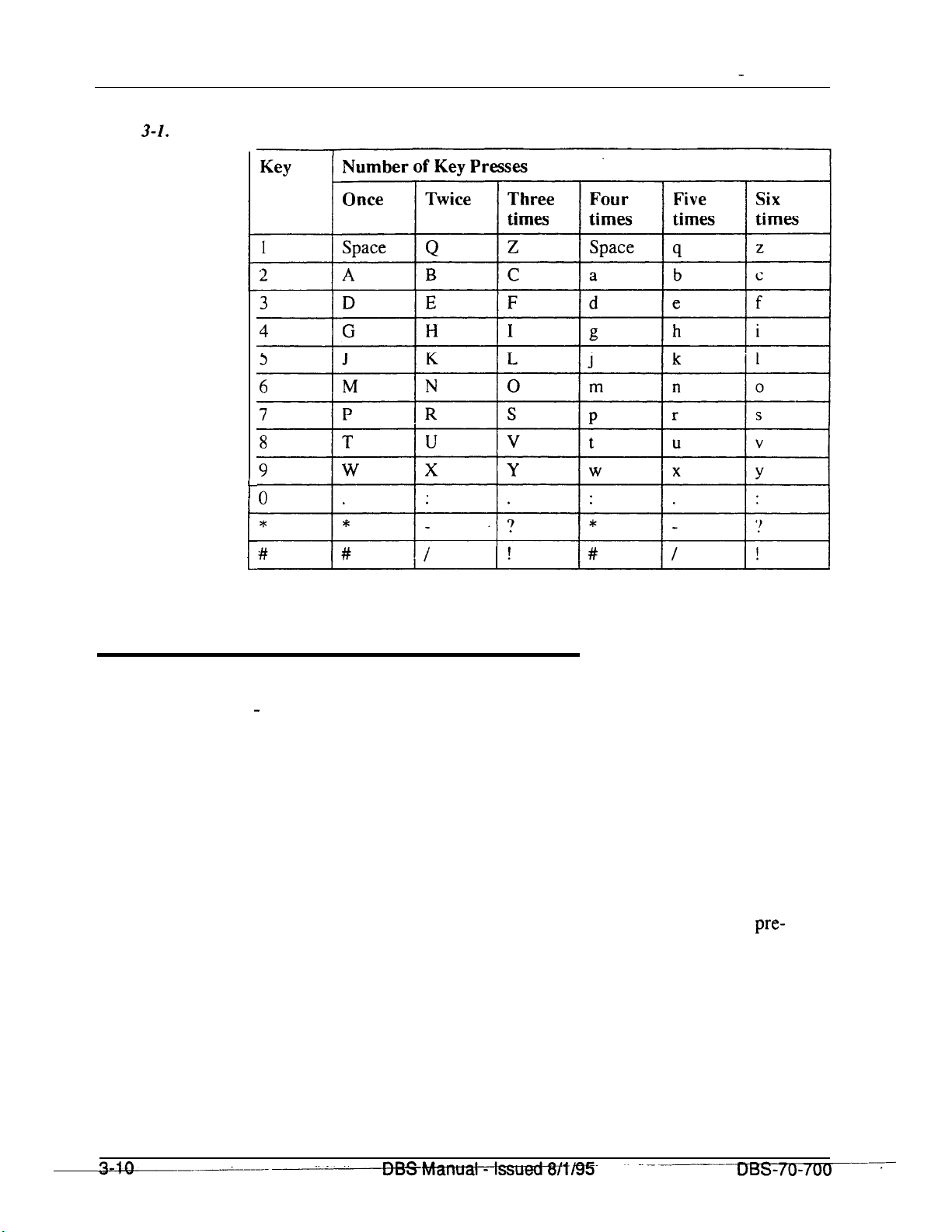
Chapter 3. Attendant Features
Section 700 - Operation
Table 3-1.
Key sequences for text assignment.
I-
i-
I
lt
Attendant Feature Package
(CPC-B Version 2.0 - 4.0)
Description
The Attendant Feature Package (AFP) software affects the attendant’s DSS
console.
Note: The Attendant Feature Package was discontinued in CPC-B Version
5.0.
When the AFP is installed, the DSS console provides the following
configured features:
l Z O-7 (Paging Zones)
l
P O-9 (Park keys)
l NIGHT key
l BUSY key
pre-
Technical Manuals Online! - http://www.tech-man.com

Section 700
-
Operation
l WAIT key
l OHVA key
l EXT key
l SSD key
l STATE key
l RESET key
l ALM key
l MSG key
l CNCT (connect) key
l CNCL (Cancel) key
l
Chapter 3. Attendant
Configuration of line/loop keys on large display as multiline
Features
l
Ability to assign line/loop keys to FF keys
l
26 search keys for extensions
l 2 arrow keys.
Attendant Groups
(CPC-AIL
Description
and CPC-B Version 2.0 or higher)
The DBS can accommodate up to four attendant positions. The first attendant
is fixed at port 1, extension 100. The other Attendants can be set to any port
or extension. When there is more than one attendant in a system, you can
create an Attendant Group with a pilot number of 0.
When all Multi-Line keys on the first attendant phone are busy, internal calls
are forwarded to the second, third, and fourth attendant phones, in that order.
Related Programming
l
FFl
(System): Second Attendant Position
l
FFl
(System): Third Attendant Position
Technical Manuals Online! - http://www.tech-man.com
DESIvIanual -
Issued
8/l/95
3-11

ChaDter
3. Attendant Features
Considerations
Section 700 - Operation
l
FFl
(System): Fourth Attendant Position
l
FFl
(System): Attendant Transfer Extension
l If all ML keys on all attendants are busy, internal calls are transferred to a
preset destination, which must be a real extension number. The forwarding
destination cannot be the pilot number of a hunt group.
c
l The third and fourth attendants cannot have a
l Prior to CPC-B Version 2.0, the DBS supported a maximum of two
DSS/72.
attendant positions.
l In previous software releases, if a user dialed “0” for the attendant group
but the first attendant had call forwarding activated, the call would skip to
the next attendant in the group. For example, if the first attendant activated
call forwarding--busy/no answer. the dial “0” call would skip to the second
attendant. If
ai:
attendants in the group activated call forwarding, dial “0”
calls did not reach the group.
Beginning with CPC-B Version 5.0, dial
“0”
calls ring the first attendant,
even if the first attendant has call forwarding activated. However, if a call is
unanswered, it does not skip to the next attendant. The call continues to
ring the first attendant until the caller hangs up.
l
DSLTs and
l Ringing assignments will be required for all attendants other than
Attendant Position 1 (Port 1) and Attendant
SLTs
cannot
be used for attendant positions.
Postion
2 (when assigned to
port 2).
*
Dial Tone Disable
(All Versions)
Description
The intercom dial tone can be turned off at an attendant phone. Dial tone is
turned off when a headset is used.
--
Technical Manuals Online! - http://www.tech-man.com
DBS Manual - Issued
8/l/95
-
DBS-70-700

Section 700 - Operation
Operation
To disable the intercom dial tone:
1.
Press the ON/OFF key.
l The phone issues intercom dial tone.
l
The
ON/OFF
LED lights.
Chapter 3. Attendant Features
DSSl72
(All Versions)
Description
2. Press
3.
To reactivate dial tone:
The
‘Y/50.”
Press the
The
Repeat the preceding steps.
DSS/72
ON/OFF
ON/OFF
is a 72-key console that can be attached to the attendant phone.
key.
LED goes off.
The 72 keys of the DSS can be programmed as Direct Station Select (DSS)
keys for internal lines, in addition to providing direct station selection, the
DSS keys also provide busy lamp fields to assist the attendant in monitoring
the status of extensions.
The attendant can perform a simplified call transfer by pressing a DSS key
while connected to an outside line. The outside line is placed on hold and the
extension is dialed automatically.
When the attendant is placed in the programming mode, the DSS can be used
for inputting text names. Figure 3-l shows which keys are pressed for text
input.
Technical Manuals Online! - http://www.tech-man.com

Chapter 3. Attendant Features
Section 700 - Operation
Figure 3-1. VB-43225
OL
0)
,
,
I
,
,
,
,
,
,
I
with
a
DW72
?%fz20
John
PERSONAL
SYSTEM DIAL
EXTENSION
FUNCTION
HELP
Sun AUG 21
DI,?
I
can be used as an Attendant Console. The attendant console provides station
monitoring and call transfer by name for large systems, even if a large display
phone is not used.
Note: Beginning with CPC-B Version 5.0, the Attendant Feature Package
(AFP)
is no longer available.
As Figure 3-2 illustrates, the Attendant Console includes preassigned keys for
attendant functions, such as Call Park, Zone Paging, and alarm monitoring.
For a detailed description of the Attendant Console, see the
Console User’s
Guiak
(Section 760).
Technical Manuals Online! - http://www.tech-man.com
l? (VR-4
3_730‘)
. .
the
DSS/72
,
Attendant
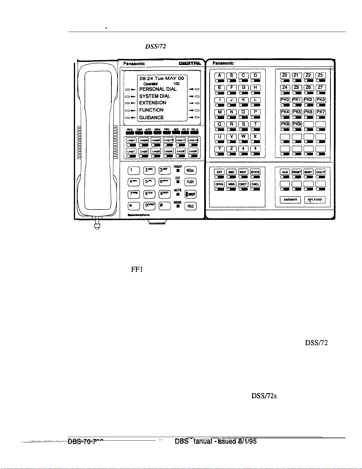
Section 700 - Operation
Chapter 3. Attendant Features
Figure 3-2. VB-43225 with a DSS/72 configured as an Attendant Console
Related Programming
l
FFl
(System): Attendant Feature Package Settings
Note: Beginning with CPC-B Version 5.0, the Attendant Feature Package
(AFP) is no longer provided.
l FF3 (Extensions): Terminal Type
Hardware Requirements
l
The “Attendant Feature Package” is required to configure the
Attendant Console. The “Attendant Feature Package” is contained on a
special EPROM chip that replaces an EPROM on the CPC-B card.
Note: Beginning with CPC-B Version 5.0, the Attendant Feature Package
(AFP) is no longer provided.
l
The following table shows the number of
Consoles that can be used.
DSS/72s
DSW72
and or Attendant
as an
nn--
.~.
Technical Manuals Online! - http://www.tech-man.com
_ -a”ua.. _ ~~~---
M
I
I
---
8/l I95
3-15
 Loading...