

Panasonic”
x-v
Mama=
Digital Business System
Section 400
Programming
Technical Manuals Online! - http://www.tech-man.com
Dot.
Iss
Part
1
ued 8/l
No.
7Ll
I
J
I
I95
3182A2
I
IDJ

The contents of this manual are subject to change without notice and do not constitute a
commitment on the part of Panasonic Communications & Systems Company (PCSC). Every
effort has been made to ensure the accuracy of this document. However, due to ongoing product
improvements and revisions, Panasonic cannot guarantee the accuracy of printed material after
the date of publication nor can it accept responsibility for errors or omissions. Panasonic will
update and revise this document as needed.
The software and hardware described in this document may be used or copied only in accordance
with the terms of the license pertaining to said software or hardware.
Reproduction, publication, or duplication of this manual, or any part thereof, in any manner,
mechanically, electronically, or photographically, is prohibited without permission of the
Panasonic Communications & Systems Company (PCSC).
@Copyright 1995 by Panasonic Communications dr Systems Company
All rights reserved.
Technical Manuals Online! - http://www.tech-man.com

Section
About This Section
400-Table
of Contents
Structure
FF Key Programming
Program Sequence
..........................................................................................................................
.....................................................................................................
.......................................................................................................... xvii
Introduction to DBS Programming
Before You Begin
Preparations for Programming
Initializing
Upgrading CPC-B Software (New Function Reset)
Understanding FF Key Programming
Program
HowtoEnter
Example Programming
Structure ......................................................................................................
Default Program Settings
................................................................................................
...................................................................................
DBS
Systems
(RAMCLR)
......................................................................
..................................................
..............................................................
the
Programming
Entry
Mode.. .....................................................................
....................................................................................
. . . . . . . . . . . . . . . . . . . . . . . . . . . . . . . . . . . . . . . . . . . . . . . . . . . . . . . . . . . . ..*....................
xvii
xvii
Intro-3
Inuo-3
Intro-4
Intro-5
Intro-6
Intro-6
Intro-7
Intro-9
Intro-9
Chapter 1. System Programming
Date and Time Settings
Day/Date Setting
Time Setting
....................................................................................................................
General System Settings
Call Duration Display
SMDR Display Start Tier for CO Calls
Least Cost Routing
Override Toll Restriction With SSD Numbers
SSD Display Restriction
Auto Flash Redial
One Touch Dial
Onhook
Key Bank Hold
Non-Appearing Trunk Hold
SLT Flash Control
Extension Number Digits
DBS-70-400
Transfer
.............................................................................................
.............................................................................................................
............................................................................................
......................................................................................................
........................................................................
(LCR)
Access
..................................................................................................
..........................................................................................................
..............................................................................................................
............................................................................................................
..............................................................................................................
.........................................................................................................
...............................................................................................
...................................................................................
................................................................
...........................................................................................
DBS Manual - Issued
(FFI)
8/l/95
1-3
l-3
l-4
l-5
l-5
l-6
1-7
l-8
l-9
l-10
1-11
1-12
1-13
1-14
1-15
1-17
- III -
. . .
Technical Manuals Online! - http://www.tech-man.com
Table of Contents
Section
400-Programming
Alternate Attendant
Attendant Intercom Calling
Extension Intercom Calling
Alert Tone for Voice Calls
........................................................................................................
...........................................................................................
...........................................................................................
.............................................................................................
Alert Tone for Busy Override&OHVA
System Installation Area Code
SSD Name Display
APVAEC
Slot Assignment
Voice Mail Busy Tone
........................................................................................................
...................................................................................................
Analog Transfer Ring Pattern
Attendant Overflow for
Delayed Ring
.................................................................................................................
Primary
AEC Disconnect Signal Duration..
Second Attendant Position
Third Attendant Position
................................................................................................
Fourth Attendant Position
Attendant Transfer Extension
Attendant Override
........................................................................................................
Attendant LED Alarm Indication
Extension (BLF) Delayed Ring
Analog Transfer Ring Pattern
Mu! tiple DID/DNIS
Page Duration
SLT DISA Ring Pattern
.......................................................................................................
................................................................................................................
.................................................................................................
AEC Disconnect Signal Duration
DID/DNIS to a Voice Mailbox
DID/DNIS
Answer Code
LCD Timer for Caller ID
Internal Hold Tone
..........................................................................................................
Door Opener Access Code Required
................................................................................................................
API Port
API
Baud Rate
Type
”
.........................
......................................................................................
............................................................................................
........................................................................................
Attendant..
................................................................................
.............................................................................................
..............................................................................................
........................................................................................
..................................................................................
.....................................................................................
........................................................................................
..................................................................................
......................................................................................
...............................................................................................
...............................................................................................
.............................................................................
....................................................................................
.:
1-18
1-19
I-20
1-21
.......................................................................
l-22
l-23
l-24
l-2.5
l-26
l-27
.................................................................
l-28
l-29
l-30
1-31
l-32
l-33
l-34
l-35
l-36
l-37
l-38
1-39
1-41
1-32
l-43
l-44
l-46
1-48
l-49
l-50
1-51
1-52
Serial Port Parameters (TTY Settings)
Parity Check
Odd/Even Parity
Baud Rate
Stop Bit Length
Data Length
SMDR Printing Mode 1: Outbound and Inbound
...................................................................................................................
.............................................................................................................
.......................................................................................................................
..............................................................................................................
....................................................................................................................
...................................................................
..........................................................
SMDR Printing Mode 2: Long-Di stance and Local Calls
3:
SMDR Printing Mode
Serial
RAI Baud Rate
-
iv
-
Technical Manuals Online! - http://www.tech-man.com
Port Flow Control (XON / XOFF)
...............................................................................................................
Header Title..
DBS Manual - Issued
.........................................................................
......................................................................
.............................................
8/l/95
1-53
l-53
1-54
l-55
l-56
l-57
l-58
l-59
l-60
1-61
1-62
DBS-70-400
Section
400~Programming
Table of Contents
PBX Settings
PBX Access Code(s)
Automatic Pause Position for PBX Access Codes
External (UNA) Relay Control
Ring Patterns for UNA Terminals (M, C and B)
External Page Interface Control for Paging Groups
Class of Service
Extension Class of Service
Account Codes
Verified Forced Account Codes
Toll Restriction for Verified Forced Account Codes
Flexible Function Screens
Flexible Function Screen Soft-Key Assignment
Flexible
Flexible Function Screen Default
Flexible Function Screens Default (All)
Caller ID Automatic DISA
Automatic DISA Callers..
..............................................................................................................
......................................................................................................
.................................................................................
.........................................................................................................
............................................................................................
...........................................................................................................
...................................................................................
........................................................................................
Function Screen Text..
.....................................................................................
..................................................................................
........................................................................
.......................................................................................
..............................................................................................
1-63
1-63
........................................................
l-64
l-66
...........................................................
......................................................
l-66
l-67
l-68
l-68
l-70
l-70
.....................................................
l-72
l-73
...........................................................
l-73
1-78
l-79
I-80
i-81
1-8 1
Door Phones
Door Phone Extensions
Door Phone Ring Assignments..
Door Opener Access Code
Door Phone Tone Type..
Door Phone Ring Timeout Timer
Door Phone Ring Pattern
Door Opener Relay Timer
System Timers
Automatic Night
Attendant Hold Recall Timer for CO Calls
Extension Hold Recall Timer for CO Calls
Attendant Transfer Recall Timer for CO Calls
Extension Transfer Recall Timer for CO Calls
Attendant Hunt Group Recall Timer
Extension Hunt Group Recall Timer
Attendant Park Hold Recall Timer
Extension Park
Attendant Call Reversion Timer for CO Calls
Unsupervised Conference Timer
Automatic Pause Timer
..............................................................................................................
..................................................................................................
....................................................................................
.............................................................................................
................................................................................................
..................................................................................
...............................................................................................
.............................................................................................
............................................................................................................
Mode
Hold
Start Time
Recall Timer
...............................................................................................
................................................................................
.............................................................................
.............................................................................
................................................................................
..............................................................................I- 100
.................................................................................
1-82
1-82
l-84
1-86
l-87
1-88
l-89
l-90
1-91
1-91
...................................................................
...................................................................
..............................................................
.............................................................
.............................................................
1-93
1-94
1-95
l-96
1-97
1-98
1-99
l-101
l-102
l-103
DBS-70-400
Technical Manuals Online! - http://www.tech-man.com
DBS Manual - issued
8/l/95
-V-
3ec;w
I
4uu-rrogrammlng
CO Flash Timer
SLT
Onhook
CO Ring Cycle Detection Timer
Inbound Ring Cycle Expansion Timer
Dial Pause Timer
PBX Flash Timer
Call Forward-No Answer Timer
Outbound Ground
Inbound Ground Start Detection Timer
...........................................................................................................
Flash Timer
............................................................................................
.................................................................................
........................................................................
.........................................................................................................
.........................................................................................................
..................................................................................
Start Detection
Timer
....................................................................
.......................................................................
Attendant Hold Recall Timer for Intercom Calls
Extension Hold Recall Timer for Intercom Calls
Attendant Transfer Recall Timer for Intercom Calls
Extension Transfer Recall Timer for Intercom Calls
CO Delayed Ring Timer
Extension (DSQBLF) Delayed Ring Timer
Hunt Group No Answer Timer
Automatic
Day Mode
Automatic Night 2 Mode Start Time
Programming and DISA Codes
Remote Programming ID Code
DISA Inbound Call ID Code
DISA Outbound Call ID Code 1
DISA Outbound Call ID Code 2
ID Code for System Programming
..............................................................................................
................................................................
....................................................................................
Start Time..
...............................................................................
...........................................................................
. . . . . . . . . . . . . . . . . . . . . . . . . . . . . . . . . . . . . . . . . . . . . . . . . . . . . . . . . . . . . . . . . . . . . . . . . . . . .
. . . . . . . . . . . . . . . . . . . . . . . . . . . . . . . . . . . . . . . . . . . . . . . . . . . . . . . . . . . . . . . . . . . . . . . . . . . . . . . . . . .
. . . . . . . . . . . . . . . . . . . . . . . . . . . . . . . . . . . . . . . . . . . . . . . . . . . . . . . . . . . . . . . . . . . . . . . . . . . . . . . . . . . . . . .
. . . . . . . . . . . . . . . . . . . . . . . . . . . . . . . . . . . . . . . . . . . . . . . . . . . . . . . . . . . . . . . . . . . . . . . . . . . . . . . . . .
. . . . . . . . . . . . . . . . . . . . . . . . . . . . . . . . . . . . . . . . . . . . . . . . . . . . . . . . . . . . . . . . . . . . . . . . . . . . . . . . . .
. . . . . . . . . . . . . . . . . . . . . . . . . . . . . . . . . . . . . . . . . . . . . . . . . . . . . . . . . . . . . . . . . . . . . . . . . . . . . .
l-104
l-
l-107
l-108
l-
l-110
l-111
l-l 12
1-113
........................................................
........................................................
...................................................
...................................................
1-114
1-115
1-116
1-117
1-118
l-120
1-122
1-123
1-125
1-127
1-127
1-128
1-129
l-130
1-131
106
109
New Function Reset
New Function Reset
. . . . . . . . . . . . . . . . . . . . . . . . . . . . . . . . . . . . . . . . . . . . . . . . . . . . . . . . . . . . . . . . . . . . . . . . . . . . . . . . . . . . . . . . . . . . . . . .
. . . . . . . . . . . . . . . . . . . . . . . . . . . . . . . . . . . . . . . . . . . . . . . . . . . . . . . . . . . . . . . . . . . . . . . . . . . . . . . . . . . . . . . . . . . . . . . . . . . . .
Confirm New Function Reset
DID/DNIS and Tl Settings
Inbound
System Configuration
Sync Source 1
Sync Source 2
Sync Source 3
Network Re-Sync Timer
Disconnect Timer
Guard Timer
Release Acknowledge Timer
Outpulse
Wink Timeout Timer
Incoming Detection Timer
Answer Supervision Timer
Immediate Glare Timer
DID
Dial Numbers
..................................................................................................
..............................................................................................................
..............................................................................................................
..............................................................................................................
..........................................................................................................
.................................................................................................................
Delay Timer
..................................................................................................
...................................................................................................
................................................................................................
1-132
1-132
. . . . . . . . . . . . . . . . . . . . . . . . . . . . . . . . . . . . . . . . . . . . . . . . . . . . . . . . . . . . . . . . . . . . . . . . . . . . . . . . . . . . . .
1-132
..................................................................................... 1-133
........................................................................................
..............................................................................................
.......................................................................................
...........................................................................................
..........................................................................................
1-133
1-135
1-141
1-143
1-144
1-145
1-146
1-147
1-148
1-149
l-150
1-151
1-152
1-153
-
vi
-
Technical Manuals Online! - http://www.tech-man.com
DBS Manual - Issued
8/l/95
DBS-70-400
Wink Glare Timer.. ......................................................................................................
Digital Pad Settings
Trunk Configuration
.....................................................................................................
....................................................................................................
Number of TlChannels.. .............................................................................................
Frame Format
Line Coding
Failure Mode
Remote
Yellow Alarm
Flash Key Operation
Red Alarm Detection
Yellow Alarm Detection
Yellow Alarm Recovery
Other Alarms Detection
Other Alarms Recovery
Frame Loss Counter
Slip Counter
Red Alarm Counter
Loss of Signal Counter
Sync Loss Counter
Yellow
Alarm
Yellow Alarm
Red Alarm Relay
Sync Loss
Frame Loss Relay
AIS
Relay
Relay Reset
Tl
Trunk Type Emulation
DID/DNIS
Outgoing Signaling Type
Incoming SignalingType..
Trunk Mode
Robbed Bit Setting
Incoming Dialing Method
Dial Tone Transmission
Busy Tone Transmission
Dial Tone Receive
Ringback Tone Transmission
DNIS
DID/DNTS
Tl
Number Setting..
Trunk Closure
...............................................................................................................
.................................................................................................................
................................................................................................................ 1-162
Loopback
........................................................................................................
Send .....................................................................................................
....................................................................................................
...................................................................................................
..............................................................................................
..............................................................................................
...............................................................................................
...............................................................................................
.....................................................................................................
.................................................................................................................
......................................................................................................
................................................................................................
.......................................................................................................
Counter.................................................................................................
Relay ....................................................................................................
.........................................................................................................
Relay..
........................................
.
................................................................
........................................................................................................
.....................................................................................................................
..................................................................................................................
...........................................................................................
....................................................................................................................
.............................................................................................
...........................................................................................
.................................................................................................................
....................................................................................................... l-191
............................................................................................
...............................................................................................
.............................................................................................
.......................................................................................................
......................................................................................
................................................................................................
Flexible
Ringing Assignments
..................................................................
.........................................................................................................
l-154
l-155
l-
I-159
l-160
1-161
1-163
l-164
1-165
1-166
1-167
l-169
l-171
l-i73
1-174
l-175
1-176
1-177
1-178
l-179
l-180
l-181
I-
1-183
1-184
l-185
l-186
1-187
1-188
l-189
l-190
1-192
l-193
1-194
l-195
1-196
1-197
1-198
l-200
158
.
182
DBS-70-400
Technical Manuals Online! - http://www.tech-man.com
DBS Manual - Issued
8/l/95
-
vii
-
Chapter 2. Trunk Programming (FF2)
Trunk Port Operation
DTMF/Pulse Dialing for Trunks
Pooled Trunk Access for Group
Pooled Trunk Access for Groups
Trunk Port Type
DISA Auto
Answer..
Private Trunk Line
Automatic
Dial
Tone Detection..
Pause for
.......................................................................................................
......................................................................................
................................................................................
“9”
“8
l-86”
....................................................................... 2-6
...............................................................................................................
........................................................................................................
...........................................................................................................
PBX Line .....................................................................................
.....................................................................................................
Outbound DTMF Signal Duration for Auto-Dialed Digits
Unsupervised
Trunk
Inbound Ring Pattern
Trunk Disconnect Detection Timer
DISA Start Time
DISA
.
Trunk Circuit
..
DID
End
Time
Type
Immediate or Wink Start
Wink Start Timer
Time Out for
Dialed
DID Interdigit Timeout
.
Trunk Port Class
Conference ...................................................................................
.....................................................................................................
............................................................................... 2-15
............................................................................................................
.............................................................................................................
........................................................................................................
.......................................................................................
...........................................................................................................
DID
Digits..
..................................................................................
..................................................................................................
............................................................................................................. 2-25
22- 11
...........................................
2-12
2- 13
2-14
2-16
2-17
2- 18
2-21
2-22
2-23
2-24
2-3
2-4
2-5
A
3-7
2-8
2-9
10
.
Chapter 3. Extension Programming (FF3)
Extension Numbers
Terminal Type..
EM/24 Port Assignment
Forced
Least
Cost
Forced Account
Extension Lockout Code..
Offhook
Call
Signal (CO)
Waiting/OHVA
Busy Override Send
Busy Override Receive
Prime Line
Pickup
Auto Pickup (Ringing Line)
Unsupervised Conference
Station Message Detail Recorder (SMDR) Report
Offhook
Offhook
Signal Volume
Signal Pattern
PSD Name Display on Large-Sized LCD Phones
. . .
- VIII -
..........................................................................................................
................................................................................................................
...................................................................................................
Routing ...............................................................................................
Codes..
...................................................................................................
..............................................................................................
.....................................................................................................
......................................................................................................
....................................................................................................... 3-13
..................................................................................................
.........................................................................................................
.......................................................................................... 3-16
.............................................................................................. 3-17
........................................................
.................................................................................................
..................................................................................................
.........................................................
DBS
Manual -
Issued
8/l/95
3-3
3-5
3-7
3-8
3-9
3-10
3-11
3- 12
3-14
3-
15
3-18
3-19
3-20
3-21
DBS-70-400
.
Technical Manuals Online! - http://www.tech-man.com
. --.-
-.
I--
“J’U”
. . . . . . .
--W..“..
J
-1....,...w
Page Group Extensions..
Display When
Idle
Display During Intercom Dial Tone
Display When Calling an Extension
Display
Display
When Accessing
When Conversingona
Display When Receiving a Page
Display After Receiving a Call Waiting Tone
Display When Dialing a Busy Extension
Extension Directory Display
Extension
Class
of Service Assignment
Inbound DID Dial Numbers
AEC Disconnect
............................................................................................................
Ringback Tone From ML Keys
Station
SLT Hookflash
Port Class..
...............................................................................................................
Extension Ring Pattern
Digital SLT Receiving Volume
Auto Set Relocation Code
Permanent Call Forward Type
Permanent Call Forward Extension
ML/MC0 Separation
VAU Hunting Priority
AEC Disconnect
VAU
Port Assignment..
Hot
Dial Pad.. .................................................................................................................
............................................................................................................ 3-55
Auto-Redial on Extensions
................................................................................................
.........................................................................................................
..............................................................................
..............................................................................
CO Dial Tone .......................................................................
CO
Trunk..
..................................................................
....................................................................................
...............................................................
......................................................................
..........................................................................................
........................................................................ 3-40
..........................................................................................
.............................................
.....................................
i..
.........................................................................................................
..................................................................................................
.....................................................................................
.............................................................................................. 3-49
.......................................................................................
............................................................................... 3-52
.....................................................................................................
.................................................................................................... 3-54
..................................................................................................
............................................................................................ 3-58
3-22
3-23
3-25
3-27
3-29
3-3 1
3-33
3-35
3-37
3-39
3-41
3-41
3-42
3-43
3-45
3-46
3-48
3-51
3-53
3-56
3-57
Chapter 4. Ringing and Hunt Groups (FF4)
CO Day Ring Assignments
CO Day Ring Assignments for Hunt Groups
CO Night Ring Assignments
CO Night Ring Assignments for
Hunt Group Pilot Numbers
Terminal/Circular Hunt Groups
Hunt Group Type
...........................................................................................................
Call Next Hunt Group
Hunt Group Members
Transfer Extension
.........................................................................................................
Hunt Group Transfer Timer..
Hunt Group Members
Call Coverage Group Members
DBS-70-400
Technical Manuals Online! - http://www.tech-man.com
..............................................................................................
........................................................................................... 4-5
Hunt
..............................................................................................
.......................................................................................
....................................................................................................
....................................................................................................
......................................................................................... 4-
..................................................................................... 4-18
DBS Manual - Issued
..................................................................
Groups..
4-3
4-4
.............................................................. 4-6
4-7
4-9
4-11
4-13
4-14
4-15
16
4-17....................................................................................................
-
8/l/95
ix
-
CO Delayed Day Ring Assignments
CO Delayed Day Ring Assignments for Hunt Groups
CO Delayed Night Ring Assignments
CO Delayed Night Ring Assignments for Hunt Groups
Extension Ring Table
.....................................................................................................
Extension Delayed Ring Table
CO Night 2 Ring Assignments
CO Night 2 Ring Assignments for Hunt Groups
CO Delayed Night 2 Ring Assignments
CO Delayed Night 2 Ring Assignments for Hunt Groups
.............................................................................
..................................................
...........................................................................
................................................
......................................................................................
......................................................................................
...........................................................
........................................................................ 4-29
.............................................
Chapter 5. FF Key Programming (FF5)
4-20
4-2
4-22
4-23
4-25
4-26
4-27
4-28
4-30
1
FF Key Assignments for Extensions
FF Key Assignments for DSS Consoles
Attendant Feature Package Key Assignments
...............................................................................
..........................................................................
...............................................................
5-3
5-8
5-10
Chapter 6. Name and Message Assignments (FF6)
General Notes
Extension Name
System Speed Dial Names
Personal Speed Dial Names
Absence Messages
Trunk Name Assignment
Hunt Group
Call
Waiting/OHVA
DID/DNIS
..................................................................................................................
...............................................................................................................
...............................................................................................
.............................................................................................
.
...........................................................................................................
.................................................................................................
Name Assignment..
Text Reply
...............
...................................................................................
Text Name Assignment
...............................................................................
......................................................................
.
Chapter 7. Toll Restrictions (FF7)
.
6-2
6-3
6-4
6-5
6-6
6-8
6-9
6-10
6-11
An Overview of Toll Restrictions
International Calling For TRS Types 3-6
....................................................................................
........................................................................
DTMF Signaling During Incoming Calls for TRS Types O-6
Maximum Dialed Digits For TRS Types 3-6
3-Digit
Toll
Restriction
7-Digit Toll Restriction For TRS
Dialing Plan Switch
Operator Access
.............................................................................................................
International Calling on Extensions
-X-
Technical Manuals Online! - http://www.tech-man.com
For TRS
Types
Types
.......................................................................................................
...............................................................................
DBS Manual - Issued
..................................................................
..................................................................
2-6..
..................................................................
2-6..
8/l/95
7-2
7-5
.........................................
7-6
7-7
7-8
7-9
7-10
7-11
7-12
DBS-70-400
Section
400-Programming
Table of Contents
Country Code Table..
Equal Access Code Format
Office Code Restriction Table For TRS Types 2-6
Area Code Table
Office
Special
Special Office Code Table For TRS Types 3-6
Special
Day TRS
Night TRS Types
Area Code Table
Office
Area &Office
Special
Code
Table
Area
Code
7-Digit Table
Types
Code Table
Code Table for TRS
Office Code Table For TRS
.........................................................................
............................................................................................
....................................................... 7-15
For TRS
For TRS
Table For TRS
O-7
O-7
For TRS Types 3-6 (Global
For TRS
Types
For
TRS Types
for
Trunks
for Trunks..
3-6 ............................................................................
Types
Types
3-6..........................................................................
Types 3-6 ...............................................................
.............................................................
2-6..
...................................................................
.....................................................................................
.................................................................................
Copy).
3-6
(Global
Types
3-6 (Global Copy).
Types 3-6 (Global
................................................... 7-23
Copyj
.................................................
Copy). ...................................
Chapter 8. Least Cost Routing (FF8)
An Overview of Least Cost Routing
Before Programming
LCR Setup
Activating LCR
LCR Call Processing
Using LCR With
LCR Area Codes
LCR Office Codes
Special LCR Area Codes
Special LCR Office Code Tables
Time Priority
LCR Trunk Groups
LCR Delete Tables
LCR Add Tables
...................................................................................................................
..............................................................................................................
Route
............................................................................................................
LCR..
...........................................................................................................
...................................................................................................
a
PBX
System..
.........................................
.................................................................................................
Tables..
........................................................................................................
.........................................................................................................
..........................................................................................
................................................................................
........................................................................................
...............................................................................
.
.................................................................
.....................................................................................
......................... 7-
.:.
....................................
.7-25
.7-26
13
7-14
7-16
7-
17
7- 18
7-19
7-20
7-2
7-22
7-24
8-3
8-3
8-2
8-4
8-4
8-5
8-6
8-7
8-S
8-9
8- 10
8-
12
S-13
8-14
1
Chapter 9. Copy Program Settings
Trunk Copy
Extension Copy
FF Key Copy
DBS-70-400
Technical Manuals Online! - http://www.tech-man.com
......................................................................................................................
................................................................................................................
....................................................................................................................
DBS Manual - Issued
8/l/95
(FF9)
9-3
9-4
9-5
-
xi
-
JGLLIUII wuu-riuyldlillliii~y
Chapter
System Speed Dial Numbers
Personai Speed Dial Numbers
IO.
Speed Dial Programming
.........................................................................................
.......................................................................................
Appendix A. Large-Screen Displays
Menu Screens During Different Call States (FF3
Appendix
Terminal Programming
Terminal Programming Through a CO or DISA Trunk
Terminal Programming Commands
Resuming
B.
Terminal Programming
Through a
SMDR or Bus
Monitor
Direct Connection..
................................................................................. B-2
Mode
ExtPor# 26-33#)
..................................................
..................................................
After Terminal Programming..
(FFIO)
. . . . . . . . . . . . . . . . . . Al thru
.......................
IO-3
10-5
A5
B- 1
B-2
B-3
Section
400~Index
-
xii
-
Technical Manuals Online! - http://www.tech-man.com
DBS Manual - Issued
8/l/95
DBS-70-400
sectron 4owrrogrammlng
1 acie ot Lontents
List of Figures
Figure 1. CPC memory clear switch
Figure 2. Phone keys used in programming mode
l-l.
Figure
Figure I-2.
Figure I-3.
Figure 5-I.
Figure 5-2. FF key layout on an
Figure 5-3.
Figure 6-I.
Sofi key numberingonlarge-display phones..
Example
Trunk Closure Example in a DBS 96
FF key
FF key
Key layout
of
a CO Ring Cycle and its Detection Timer
layout on
layout on a DSSl72
a 34-button phone..
of a DSSi72
.................................................................................
............................................................
(32~trunk
.................................................................
EM124
console
..........................................................................
unit
console..
..................................................................
for text
...................................................
....................................
system)
name assignment
..................................
. . . . . . . . . . . . . . . . . . . . . . . . . . . . . . . . . .
Intro-4
Intro-7
I-73
I -I
07
I-200
.5-4
5-4
.5-9
6-2
DBS-70-400
DBS Manual - issued
Technical Manuals Online! - http://www.tech-man.com
8/l/95
*..
- XIII -
Table of Contents
I.
Table
Table 2. Default program settings
DBS program
structure
. . . . . . . . . . . . . . . . . . . . . . . . . . . . . . . . . . . . . . . . . . . . . . . . . . . . . . . . . . . . . . . . . . . . . . . . . . . . . . . . . . . . . . .
Section 400-Programming
List of Tables
Intro-6
. . . . . . . . . . . . . . . . . . . . . . . . . . . . . . . . . . . . . . . . . . . . . . . . . . . . . . . . . . . . . . . . . . . . . . . . . . . . . . . . . . . . .
Intro-9
I-l.
SLT
Table
Table I-2. Analog Transfer Ring Patterns
Table l-3. AEC Disconnect Signal Duration values
Table
Table I-5.
Table I-6. Feature codes for Flexible Function Screen soft keys
Table
Table l-8.
Table I-9.
Table
Table I-11.
Table I-12. Attendant Hunt Group Recall Timer values for CO calls
Table I-13.
Table I-14.
Table I - 15.
Table I-1 6.
Table I -I 7.
.
Table
Table
Table
Table
Table
Table I-23. PBX Flash Timer values
Table I-24. Ring Control for Call Forward-No Answer Timer
Table I-25. Call Forward-No Answer Timer values
Table
Table I-27. Inbound Ground Start Detection Timer values
Table l-28. Attendant Hold Recall Timer values for intercom calls
Table l-29.
Table
Table I-3 I.
Table l-33.
Table I-34. Hunt Group No Answer Timer values
Table l-35. System Configuration for Tl installation
Table
Table I-37. TI Disconnect Timer values
I-4.
I-7.
I-IO. Attendant Transfer Recall Timer values for CO
I-18.
I -I 9. CO
I-20.
I-2 I. Inbound Ring Cycle Expansion Timer values..
I-22.
l-26.
I-30.
I-32.
Table
I-36.
Table I-38. TI Guard Timer values
Hookflash
RAI Modem
Class of Service features
Door phone
Attendant Hold Recall Timer values for CO calls
Extension Hold Recall Timer values for CO calls
Extension Transfer Recall Timer values for CO
Extension Hunt Group Recall Timer values for CO
Attendant Park Hold Recall Timer values
Extension Park Hold Recall Timer values
Attendant Call Reversion Timer values
Unsupervised Conference Timer values
Automatic Pause
Flash
SLT
Onhook
Dial Pause
Outbound Ground Start Detection
Extension Hold Recall Timer values for intercom calls
Attendant Transfer Recall Timer values for intercom calls
Extension Transfer Recall Timer values for intercom calls
CO Delayed Ring
Extension Delayed Ring Timer values
MinimumTlprogramming..
Control Settings..
Compatibility
Card
......................................................................................
timer values..
ring
Timer values..
Timer values
Flash
Timer values
....................................................................................
Timer values..
Timer values
....................................................................................
..................................................................................
...................................................................................
.........................................................................
............................................................................ I-38
.............................................................
..........................................................................
....................................................
calls..
calls..
.........................................................
....................................................... I-100
...........................................................
...........................................................
.......................................................................
....................................................................
................................................
............................................................
Timer values
.................................................
........................................................................
.............................................................
..............................................................
.........................................................
............................................................................ l-136
.............................................................................
.........................................
.
......................
...............................................
...............................................
...................................... I-95
......................................
..................................
calls..
............................................
..............................................
................................
....................................
....................................
..............................
.............................. l-117
I-15
I-43
l-62
I-68
I-74
I-88
I-93
I-94
I-96
I-97
I-98
I-99
I-IOI
l-102
I-103
I-l 04
l-l 06
I -
IO8
I-109
I-110
l-111
I-111
I -II2
l-113
I-114
l-11.5
I-116
l-118
I-120
1-122
l-135
I-146
I-147
-
xiv
-
DBS Manual - Issued
Technical Manuals Online! - http://www.tech-man.com
8/l/95
DBS-70-400
secrlon 4uwrrogrammlng
Table
I-39.
Table
l-40.
Table
l-41.
Table
I-42.
Table
I-43.
Table
I-44.
Table
l-45.
Table
l-46.
Table I-47. Digital Pad Settings - pad numbers
Table
l-48.
Table
I-49.
Table
l-50.
Table
I-51.
Table
I-52.
Table I-53. DIDIDNIS Flexible Ring settings in
Release Acknowledge Timer values
Outpulse
Wink Timeout Timer values
Incoming
Delay Timer values..
...........................;..................................................
Detection Timer values
Answer Supervision Timer values..
Immediate
Wink Glare Timer
Glare Timer values..
values..
................................................................................
Digital Pad Settings-circuit types
Digital Pad Settings
Yellow Alarm Detection
Yellow
Alarm Recovery
Other Alarms Detection
Other Alarms Recovery
-
default values
timer values..
timer values
timer values
timer values
.................................................................
......................................................................... l-149
....................................................................
..................................................................
....................................................................... l-153
.................................................................. l-155
and
...............................................................
...............................................................I - I69
...............................................................
...............................................................
diferent
I
ama
OT
related dB levels
..............................
.............................................................
CPC-B versions
.......................
c;ontenrs
I-148
I-150
I-151
I-152
I-154
I- 156
I-156
I-167
l-171
I -I 73
I-l 98
Table 2 -1.
Table 2-2. Trunk Disconnect Detection
Table 2 -3.
Table 2-4. DID Dialed Digit Timer values
Table 2 -5.
Table 2-6.
Table 3-1. Terminal. Types
Table 3-2.
Table 3-3.
Table 3-4.
Table 3-5. Soft key menus when accessing CO dial tone..
Table 3-6.
Table 3-7.
Table 3-8.
Table 3-9.
Table 3-10. Station Port Class - circuit types
Table
Table 5-I. Feature codes for FF key assignment
Ring Patterns for inbound trunk calls..
Wink Start Timer settings
........:...........................................................................
DID Interdigit Timer values..
Trunk Port Class-circuit types
.......................................................................................................
Sof
key menus
Soft key menus
Soft key menus
Soft key menus
Soft key menus
Sofr
key menus after receiving a call waiting tone
Soft key menus
3-11. Extension ring patterns
during idle mode
during
when
intercom
calling
duringatrunk call..
when receiving
when dialing
.....................................................................................
...............................................................
Timer values
...........................................................
...........................................................................
..............................................................................-2 -24
...........................................................................
........................................................................
dial tone..
an
e.utension
.........................................................
..........................................................
...................................................
.....................................................................
a page..
a busy
...............................................................
exten.sion
...................................................
.......................................................................
,...................................................:...............
..............................................
.2
-I 4
2-15
.2
-22
.2
-23
2-25
3-5
.3-23
.3-25
.3-2 7
.3-29
3-3
3-33
3-35
.3-37
3-43
.3-46
5-5
I
Table
6-1. Preset Absence Messages
Table 6-2.
Table
Table
Table
Table 7-4.
Default call
7-I.
Toll restriction
7-2.
NANP
7-3.
h4aximum
Diferences
waitinglOHVA
changes
number of dialed digits for TRS types 3-6
between. old and
DBS-70-400
types..
.......................................................................................................
O-4
text reply messages..
.............................................................................................
DBS Manual - Issued
Technical Manuals Online! - http://www.tech-man.com
................................................................................
................................................
............................................
..t
new dialing plans
........................................
.......
8/l/95
6-6
6-10
7-2
7-3
7-7
7-10
-
xv
-
Table
8-1.
Table
8-2.
Table
8-3. LCR
Table
Table 8-5. LCR trunk selection
8-4.
LCR time periods and positions used
Priority Route
Time
Priority Route
Time
table
........................................................................
Table format..
Table format..
.............................................................................................
........................................................................
......................................................................
.;.
....................................
...................................................................
8-3
8-10
8-5
S-11
8-13
Table1 O-I.
Table
Table B-l.
Table B-2. Codes for switching
DSS key filnctions
IO-2.
QSS key
Terminal programming
finctions
in System
in Personal Speed Dial programming
SMDRIBus
Speed Dial programming..
commands..
......................................................................
Monitor modes..
...................................I O-4
.................................
.................................................
IO-4
B-2
B-3
-
xvi
-
DBS Manual - issued
Technical Manuals Online! - http://www.tech-man.com
8/l/95
DBS-70-400
,About
This
Section
FF keys on a DBS key phone. (Other programming methods are described in Appendix B of this
section.)
This Section
400 is intended for use as a technical reference manual for DBS programming via the
Structure
Section
Chapter 1 covers
The FF keys categorize the programs by subject -- each FF key represents a
group of related programs as follows:
Chapter 1
Chapter 2
Chapter 3
Chapter 4
Chapter 5
Chapter 6
Chapter 7
Chapter 8
Chapter 9
Chapter 10
400 is structured according to FF key numbering. For example,
FF Key Programming
FF key programming is accomplished by entering programming mode, then
punching in each program’s address (press the FF key, then enter a string of
numbers that are separated by the pound #key). The phone’s LCD display
will show prompts while you are punching in the string, to guide you through
the programming. Within each address string (usually at the end of it), you
have a choice of numbers to press in order to set the program; the number you
press determines the program setting.
FFl
programs; Chapter 2 covers FF2 programs; and so on.
FFl
-- System
FF2 -- Trunks
FF3 -- Extensions
FF4 -- Ring Assignments & Hunt/Call Coverage Groups
FF5 -- FF Key Features
FF6 -- Displayed Names & Messages
FF7 -- Toll Restriction
FFS
-- Least Cost Routing
FFP
-- Program Copy
FFlO
-- Speed Dial Numbers
.
Once you’ve entered programming mode and punched in an FF key address,
you do not have to keep pressing the FF key to go to the next [sequential]
address -- the DBS will automatically display the next prompt after you set
the
fust
one (or press # to accept the displayed setting).
address in another FF key, simply press that FF key while still in
programming mode.
Program Sequence
Although FF key programming separates DBS programs into groups, it is
important to note that the numerical sequence of the FF keys and the
addresses within them, does not necessarily represent a logical progression
for programming a particular feature or application. For example, some DID
settings are in
(Extensions) and FF6 (Names and Messages).
In Section 400,
the feature or application it affects (if any). Also, the forms in
the DBS Manual provide a more concise view of programming DBS features.
DBS-70-400 DBS Manual - Issued
FFl
(System), while others are in FF2 (Trunks), FF3
each program explanation includes related information about
8/l/95
To jump to an
Section 450
-
xvii
of
-
Technical Manuals Online! - http://www.tech-man.com
Introduction to DBS Programming
This introduction provides an overview of DBS programming from a phone.
For descriptions of other DBS programming methods. see Appendix B of this
manual.
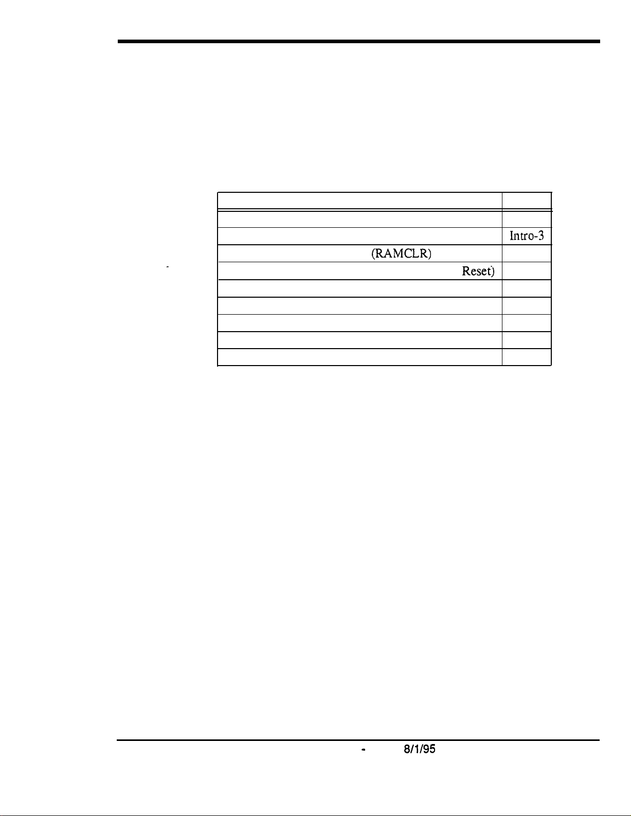
The following table summarizes the topics contained in this introduction.
Topic
Before You Begin
Preparations for Programming
Initializing DBS Systems
Upgrading CPC-B Software (New Function
Understanding FF Key Programming
Program Structure
How to Enter the Programming Mode
Example Programming Entry
Default Program Settings
(RAMCLR)
Reset)
Page
Intro-3
IllUO-3
Intro-4
Intro-5
Intro-6
Intro-6
Intro-7
Intro-9
Intro-9
DBS-70-400
Technical Manuals Online! - http://www.tech-man.com
DBS Manual - Issued
8/l/95
Intro-l

Intro-2 DBS Manual - Issued
Technical Manuals Online! - http://www.tech-man.com
8/l/95
DBS-70400
Section
400~Programming
Before You Begin
Introduction to DES Programming
This section describes preparations that should be completed
programming.
If you are familiar with FF key programming for DBS
systems, you may begin programming as soon as these preparations have
been made.
If you are new to DBS programming, be sure to read
Key Programming”
on page Intro-5 before you begin.
Preparations for Programming
Prior to programming the DBS system, make sure you have completed the
following steps:
1. Confirm that the DBS features meet customer requirements. See Section
700-Feature Operation
2. Confirm that you have the DBS hardware required for the end user. See
Section 300-Installation
3.
Use
Forms and Tables (Section 450)
Use the following guidelines when completing
l
Be sure to record
all
for DBS feature descriptions.
for details.
to record the customer’s site data.
Forms and Tables:
program entries.
before you start
“Understanding FF
l
Leave the default values for equipment that is not connected.
l
Pay careful attention to program items that require a power-down to take
effect. Be sure to complete the necessary programming in these areas
before you make the system operational.
4. To program a new DBS system, you must first initialize the software to
default values (see
“Initializing DBS Systems”,
next page). If you are
performing an upgrade and the system is using a CPC-B card, you must
first
perform
Softtiare”
Once these steps are completed, use the site data in
the New
Function Reset procedure
on page Intro-5).
(see “Upgrading CPC-B
Forms and Tables
to
program the system.
D BS-70-400
Technical Manuals Online! - http://www.tech-man.com
DBS Manual - issued
8/l/95
Intro-3
Initializing DBS Systems (RAMCLR)
After installing a new DBS system, or when upgrading to Version 7.0, you
must initialize the CPC (Central Processing Card) before programming the
system.
IMPORTANT:
This procedure
must
be performed before you program
the DBS system. Failure to initialize the CPC before programming may
cause operational problems.
The procedure described below re-initializes the entire DBS memory, and
resets all programs to their default values. This means that all programs used,
as well as features set on individual extensions, must be reprogrammed. If
you have PCAS, you can download existing settings (thru CPC Version 4.0)
and upload them to the new version. The new features introduced in CPC
Versions 5.0
thru
6. lx. as well as the Permanent Call Forwarding feature,
must be manually reprogrammed.
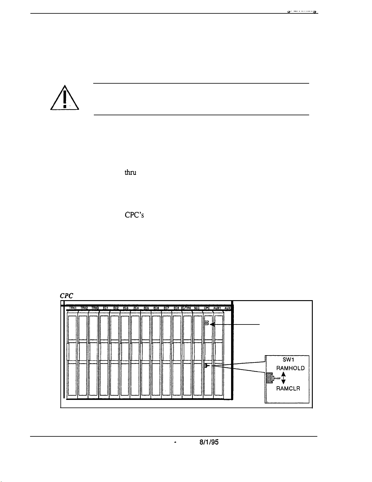
1.
Power-off the DBS (set power switch to OFF).
2.
Slide the
3.
Power-on the DBS. Wait until the bottom status LED on the CPC card
CPC’s
SW1 switch to “RAMCLR”.
stops flashing (this takes less than a minute).
4.
Slide SW 1 back to “RAMHOLD”.
Figure 1.
Intro-4
5.
From any display phone, verify the software version by pressing
ON/OFF. CONF 7777
T
memory clear switch
DBS Manual - Issued
8/l/95
STATUS
LED
DBS-70-400
Technical Manuals Online! - http://www.tech-man.com
Section 400-Programming
Introduction to DBS Programming
Upgrading CPC-B Software (New Function Reset)
Perform the following procedure when upgrading CPC-B software to a new
version.
initialized instead: see
page.
Exception:
If upgrading to Version 7.0, the system must be
“‘Initializing DBS Systems (RAMCLR)“.
previous
IMPORTANT:
Perform New Function Reset if upgrading
to a new
release -- from 5.0 to 6.0, for example. It is not necessary for a “point”
release (e.g., from 5.0 to 5.2).
New Function Reset clears unused registers and adds new programs, but
retains all current DBS settings. If you are upgrading from a CPC-B version
prior to 3.1, New Function Reset will also clear any existing DID numbers
that are
extension-based.
1. Power-off the DBS. Remove the CPC-B card.
2. Replace the existing EPROMs l-4 with new EPROMs.
3. Re-install the CPC-B card, then power the system back on.
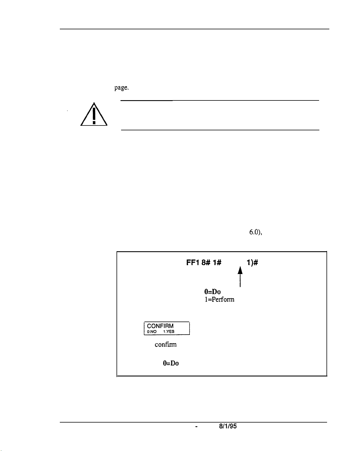
4. If upgrading to a new release (e.g., from 5.0 to
6.0),
perform New Function
Reset as shown below:
FFl 8# I#
(0 or
l)#
NOTE:
This is to
If you enter “1” (to reset), the following displays:
confirm
that you want to reset the data before the DBS
actually performs the reset. Press one of the following:
O=Do
not complete the reset.
l=Complete the reset.
5. Power-off the system, wait at least 3 seconds, then power it back on.
DBS-70-400
Technical Manuals Online! - http://www.tech-man.com
DBS Manual - Issued
t
O=Do
not perform New Function Reset.
l=Perfonn
New Function Reset.
8/l/95
Intro-5
Introduction to
DBS
Programming
Section 400-Programming
Understanding FF Key Programming
Program Structure
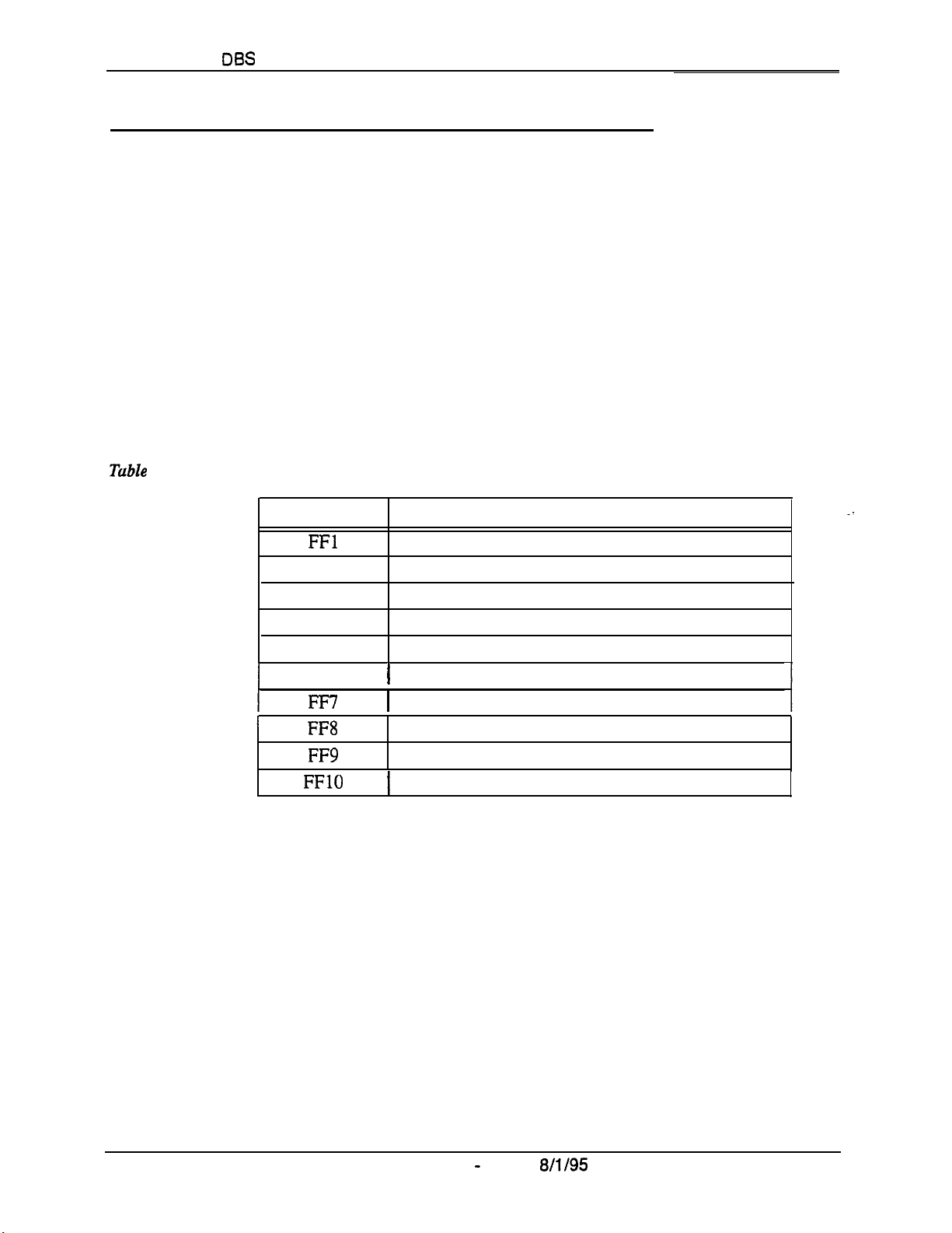
Program entries for the DBS are organized into 10 primary groups, which are
listed in Table 1 below. Each group has its own Flexible Function (FF) key
on the phone. These keys can be identified by the LED on the left side of the
key. On key telephones, the FF keys are numbered left-to-right, starting on
the bottom row.
Tuble
After you enter the programming mode
Programming Mode”,
programming the entries (“addresses”) of the group.
display will prompt you through the addresses.
1.
JIBS program structure
I
FF Key
FFl
FF2
FF3
FF4
FF5
FF6
FF7
FF8
FF9
FFlO
(see “How to Enter the
next page), press the desired
FE key to start
The phone’s LCD
Programming Group
System settings
CO Trunk settings
Extension settings
Ring Assignments and Hunt Groups
FF Key Assignments
1
Names and Messages on LCD Display
1
Toll Restrictions (TRS)
Least Cost Routing (LCR)
Copy Program Settings
1
Speed-Dialing (system and personal)
In the programming mode, some of the phone keys can be used to store your
settings and move forward or backward through the program addresses.
Figure 2 (next page) identifies these keys and what they do in programming
mode.
intro-6 DBS Manual - Issued
Technical Manuals Online! - http://www.tech-man.com
8/l/95
D BS-70-400
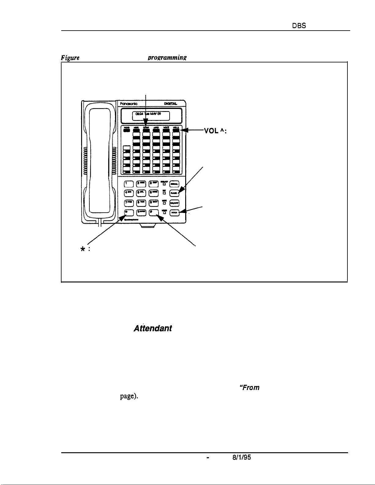
Section 400-Programming
‘imrre
2.
Phone kevs used in womamming mode
Introduction to
DES
Programming
CONF:
to default setting.
Stores your entry and
*:
moves backward (decrements
program address number).
Resets entry
VOL “:
programming level.
FLASH:
backward (decrements port number in
the same address; or decrements program
address number).
HOLD:
forward (increments port number in
the same address; or increments program
address number).
# : Stores your entry and
moves forward (increments
program address number).
Moves backward to the previous
Stores your entry and moves
Stores your entry and moves
How to Enter the Programming Mode
From the
DBS-70-400
Technical Manuals Online! - http://www.tech-man.com
Atiendant
port...
Programming can be performed from an Attendant display phone. The phone
connected to extension port 1, assigned extension number 100 is
automatically the Primary Attendant phone. By default, extension port 2
(extension number 101) is the Second Attendant phone (although this
extension assignment can be reprogrammed). Up to two other phones can
also be programmed as Third and Fourth Attendant phones. Programming is
also possible from other extensions (see
page).
To enter the programming mode from any Attendant phone, press:
ON/OFF PROG ## [desired FF key]
DBS Manual - Issued
‘%rom
8/l/95
a Non-Attendant Port”,
Intro-7
next
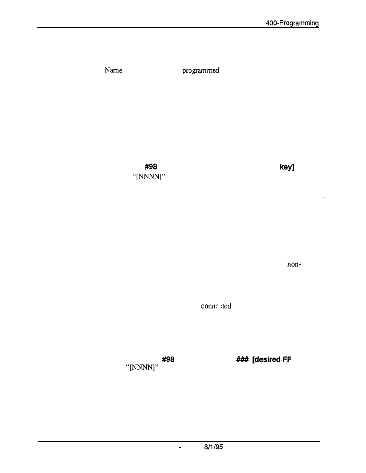
introduction to DBS Programming
Notes:
l
Name settings can only be
DSS console connected to it.
l
When you enter the programming mode on the Attendant phone -- and the
DBS is set for only one Attendant -to the “Night” mode. After you exit the programming mode (by pressing
ON/OFF), the system will return to the appropriate mode according to the
system clock and the mode’s start time.
From a non-Attendant port . . .
When programming from a display phone other than an Attendant, press:
progammed
the system will automatically change
Section
400-Programming
from the Attendant phone or a
ON/OFF
(where
#98
“[NW”
[NNNN] PROG ## [desired FF
is the programming authorization code -- “9999” by
default)
Notes:
l
In CPC-A versions prior to 3.3, if a non-Attendant phone is used for
programming, you must enter the programming authorization code twice -once to begin programming, and once to exit programming. Otherwise,
other non-Attendant extensions cannot enter the programming mode.
l
Beginning with CPC-A Version 3.3, and CPC-B versions, a non-Attendant
phone only has to enter the authorization code once, to begin
programming. As soon as programming is complete, any other non-
Attendant phone can enter the programming mode.
From the Test Terminal port . . .
You can also program from a phone connr
the main DBS cabinet:
1. Slide the SW1 switch on the cabinet to ‘Test” mode. This will provide a
direct connection to ports 7 and 8 (if the DBS is already in service, make
sure beforehand that placing ports 7 and 8 out of service is acceptable).
keyJ
.:ted
to the test terminal (CN3) of
.
i
2.
Press:
ON/OFF
#98
[NNNN] PROG
(where “[NNNNJ” is the programming authorization code -- “9999” by
default)
When you are finished programming, be sure to return SW1 to the “ST”
position.
Intro-8
Technical Manuals Online! - http://www.tech-man.com
DBS Manual - Issued
8/l/95
##### [desired.FF
DBS-70-400
key]
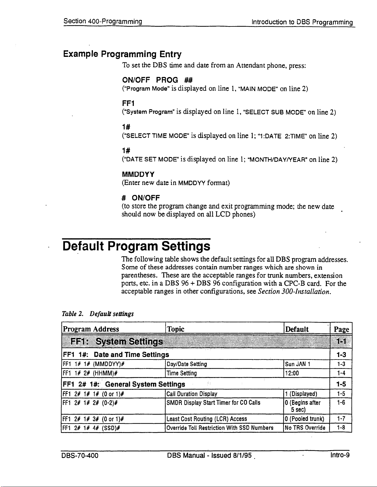
Technical Manuals Online! - http://www.tech-man.com
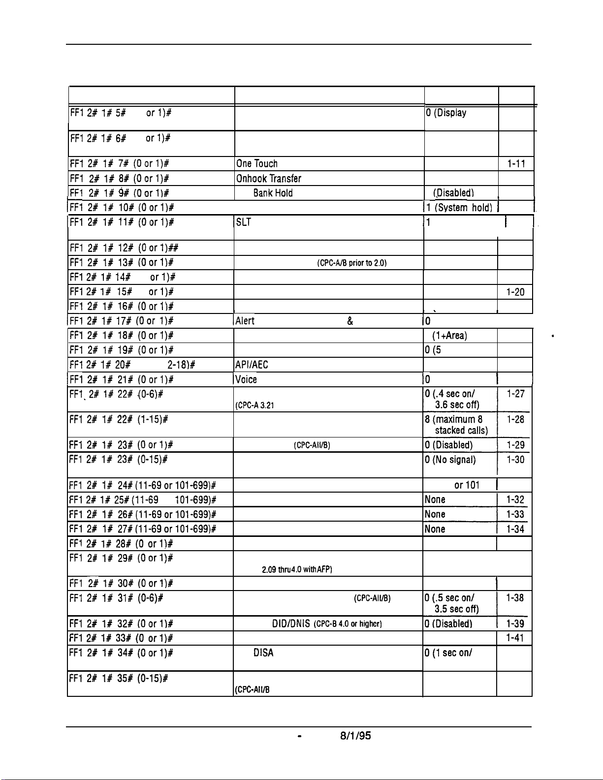
Introduction to DBS Programming Section 400-Programming
Program Address
ITI 2# I# 5#
FFl 2# 1# 6P
FFl 2f 1P 7# (Oorl)#
FFl
2#188#
FFl 2#
hi 2Rc iRc
IFFi 2# i# li# (Oorl)#
FFl 2# l# 12# (Oorl)##
FFl 2# l# 13# (Oorlj#
FFl 2# l# 14f
FFl 2#
FFl 2# l# 16# (Oorlj#
IFFi 2# i# 17# (oar I)#
FFI 2# l# 18# (Oorl)#
FFl 2# l# 19# (Oorl)#
FFl 2# l# 20#
1~~1 2# I# 21# (Oorl)#
FF1.2# l# 22# .(O-6)f
FFl 2# l# 22# (l-15)#
FFl 2# l# 23# (Oorl)#
FFl 2# l# 23f (O-15)8
FFl 2# l# 24#(11-69orlOl-699)#
FFl 2# l# 25#(11-69
FFl 2# l# 26#(11-69orlOl-699)#
FFl 2# l# 27#(11-69orlOl-699)P
FFl 2W l# 28# (0 orlj#
FFl 2# l# 29# (Oorlj#
FFl 2# l# 30# (Oorl)#
FFl 2# l# 31# (0-6)#
l#
l#
155
(0
(0
(Oorl)#
9#
(Oorlj#
io#
(0
(0
(2-9 or
orl)#
orl)#
(Oorlj#
orl)f
orl)P
2-18)#
or
101-699)#
Topic
SSD Display Restriction
Auto Flash Redial
OneTouch
OnhookTransfer
Kev
I I
/Non-Appearing Trunk Hold
ISLT
Extension Number Digits
Alternate Attendant
Attendant Intercom Calling
Extension Intercom Calling
Alert Tone for Voice Calls
I
/Alert
System Installation Area Code 1
SSD Name Display
APVAEC
IVoice Mail Busy Tone
Analog Transfer Ring Pattern
(CPGA3.21
Attendant Overflow for Primary Attendant
(CPC-B 1.0 only)
Delayed Ring
AEC Disconnect Signal Duration
(CPC-A 3.3 or higher)
Second Attendant Position
Third Attendant Position
Fourth Attendant Position
Attendant Transfer Extension
Attendant Override
Attendant LED Alarm Indication
(CPC-B
Extension (BLF) Delayed Ring
Analog Transfer Ring Pattern
Dial
BankHold
Flash Control
Tone for
B
USY
Slot Assianment
or higher)
(CPC-AIIIB)
2.09thru 4.0with AFP)
(CPWBpriorto2.0)
Override & OHVA
(CPC-Ail/B)
Default
O(Display
DBS- l-9
Page
dialed digits)
1
(REDIAL
l-10
sends flash)
1 (Enabled)
1
(Enabled)
0
(Disabledj
11 &tern hold) 1
11
(Retrieves held ) l-15
call)
!
I
l-11
1-12
1-13
1-14
1 (3 digits) l-17
1 (Enabled)
l-18
1 (Voice) 1-19
1 (Voice)
1 (Enabled)
I -
10
(Disabled)
(1tArea)
O(5
names) l-24
Noassianment
IO
(Silence)
Ext.11
or101
1 (Enabled)
1 (can assign
alarm)
0 (Disabled)
l-20
1-21
I
I l-22
l-23
l-25
t
l-26
I
l-31
1
1-35
l-36
I
1
l-37
1.
1,
0
1
FFl 2C l# 32# (Oorl)#
FFl 2# l# 33# (0 orl)#
FFl 2# l# 34# (Oorl)#
FFl 2# l# 35# (0-15j#
Intro-l 0
Multiple
Page Duration
SLT
AEC Disconnect Signal Duration
(CPC-All/B
DBS Manual - Issued
DID/DNIS
DISA
Ring Pattern
5.0 or higher)
Technical Manuals Online! - http://www.tech-man.com
(CPC-84.0orhighcr)
8/i/95
0 (Unlimited)
O(1 secon/
3 secoff)
0 (No signal sent)
.
DBS-70-400
l-41
1-42
1-43
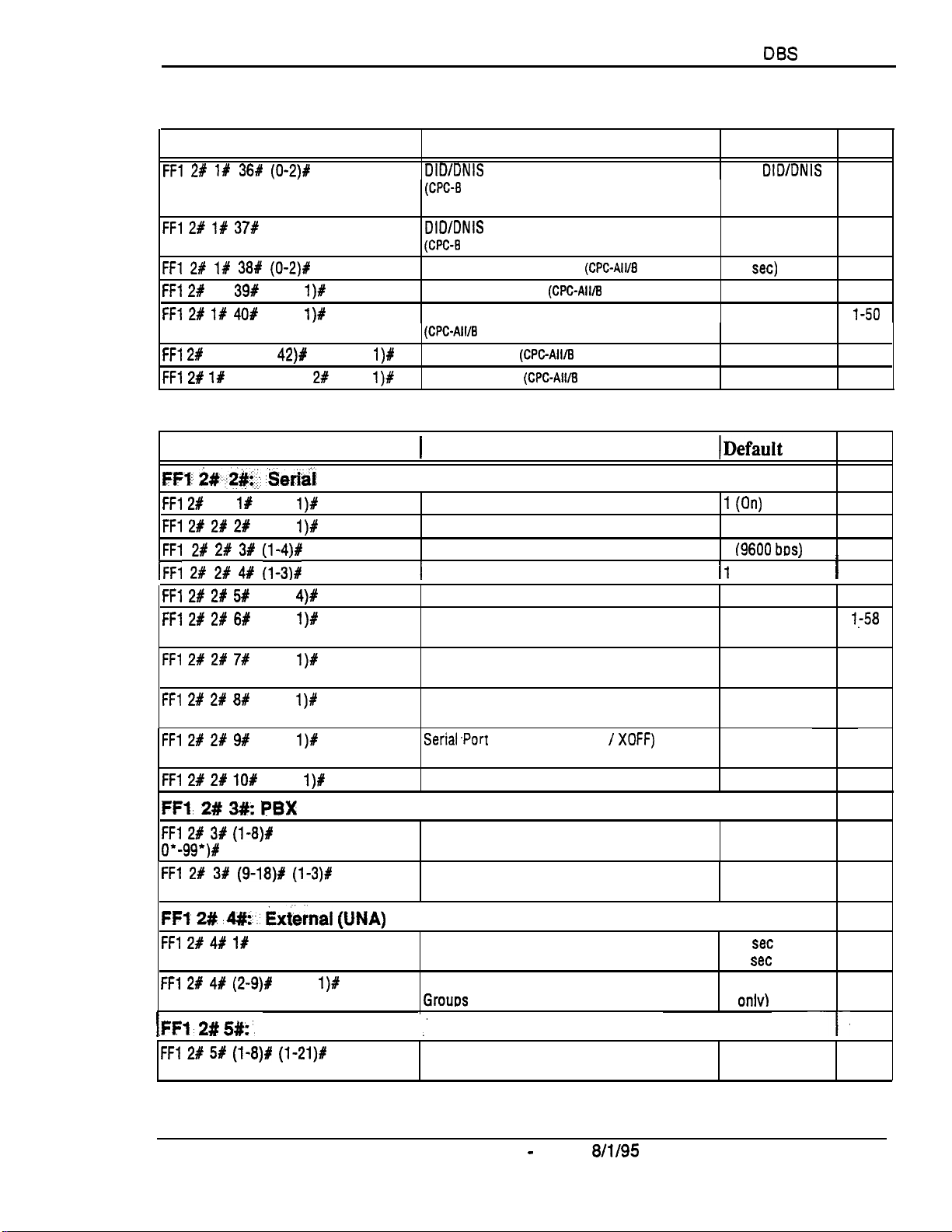
Section 400-Programming
Introduction to
DBS
Programming
Program Address
FFl 2# l# 36# (O-2)P
FFl 2P l# 37#
FFl 2t l# 38P (0-2)#
FFl 28
1X
FFl 2# If 4OP
FFl 2#
1X (41 or
FFl 2P l#
(6 char.)#
39#
(0 or
(0 or
42)#
(41 or 42)P 2f (0 or
Program Address
FFl:- *#,.2*!. ,8erid
FFl 2#
2% 1Y (0 or
FFl 2# 2f 2#
FFl
28
hi 2t 2# 4,dc ii-sir
FFl 2# 2# 51
FFl 21 2# 6#
FFl 2# 2# 7#
FFl 2# 2# 8P
FFl 2# 2# 9#
FFl 2# 2# lO#
2#
(0 or
3#
(3 or
(0 or
(0 or
(0 or
(0 or
l)#
l)#
(l-4)#
4)#
l)#
l)#
l)#
1)X
(0 or
Topic
l)#
1)P
1X (0 or
l)#
l)#
DID/DNIS
(CPC-8
DID/DNIS Answer Code
(CPC-8
LCD Timer for Caller ID
Internal Hold Tone
Door Opener Access Code Required
(CPC-AWE
API Port Type
API Baud Rate
1
Topic
to a Voice Mailbox
6.0 or higher)
6.0 or higher)
(CPC-All/l3
7.0 or higher)
(CPCAWE
(CPC-All/B
Port Parameters (TTY Settings)
Parity Check
Odd/Even Parity
Baud
Rate
1
Stop Bit Length
Data Length
SMDR Printing Mode 1: Outbound and Inbound 1 (Outbound and
SMDR Printing Mode 2: Long-Distance and 1 (Long-distance
Local Calls and local)
SMDR Printing Mode 3: Header Title 0 (No header
Serial.Port Flow Control (XON /
l)#
RAI Baud Rate
(CPC-AH/B
7.0 or higher)
7.0 or higher)
7.0 or higher)
XOFF)
6.1 or higher)
Default
0 (No
DIDIDNIS
digits transmitted)
None
0 (5
set)
0 (Disabled)
0 (Not required)
0 (Standard API)
0 (9600 bps)
IDefault
1 (On)
1 (Even)
4
19600
bos)
.
I .
11
(1 bit)
4 (8 bits)
Inbound)
titles)
1 (No DBS flow
control)
0 (300 bps)
I
Page
1-44
l-46
1-48
1-49
l-50
1-51
1-52
Page
1-53
l-53
l-54
l-55
I
1
l-56
l-57
l,-58
l-59
l-60
1-61
l-62
FFl, 2# 3#: PBX
FFl 2P 3f (l-8)1%
o*-99ya
FFl 2# 3P (9-18)# (l -3)#
FF1
2#
d#z-.: Exknal (UNA)
FFl 28 4# 1Y
FFl 2# 4# (2-9)Y
,FFl- 2# 5#:.
I
FFl 2# 5P (l-8)# (l-21)W
(0 or 1)#
D BS-70-400
Settings
(O-999 or
Relay Control
(0 or
l)#
Class of Service
(0 or 1)#
PBX Access Code(s)
Automatic Pause Position for PBX Access
Codes
Ring Patterns for UNA Terminals (M, C and B)
External Page Interface Control for Paging
Grouts
,’
Extension Class of Service
DBS Manual - issued
Technical Manuals Online! - http://www.tech-man.com
8/l/95
1-63
None
None
1-63
l-64
1-66
0 (1
set
on/ l-66
3
set
off)
0 (Internal paging l-67
onlv)
1-68
1
0 (All features
disabled)
1-68
Intro-11
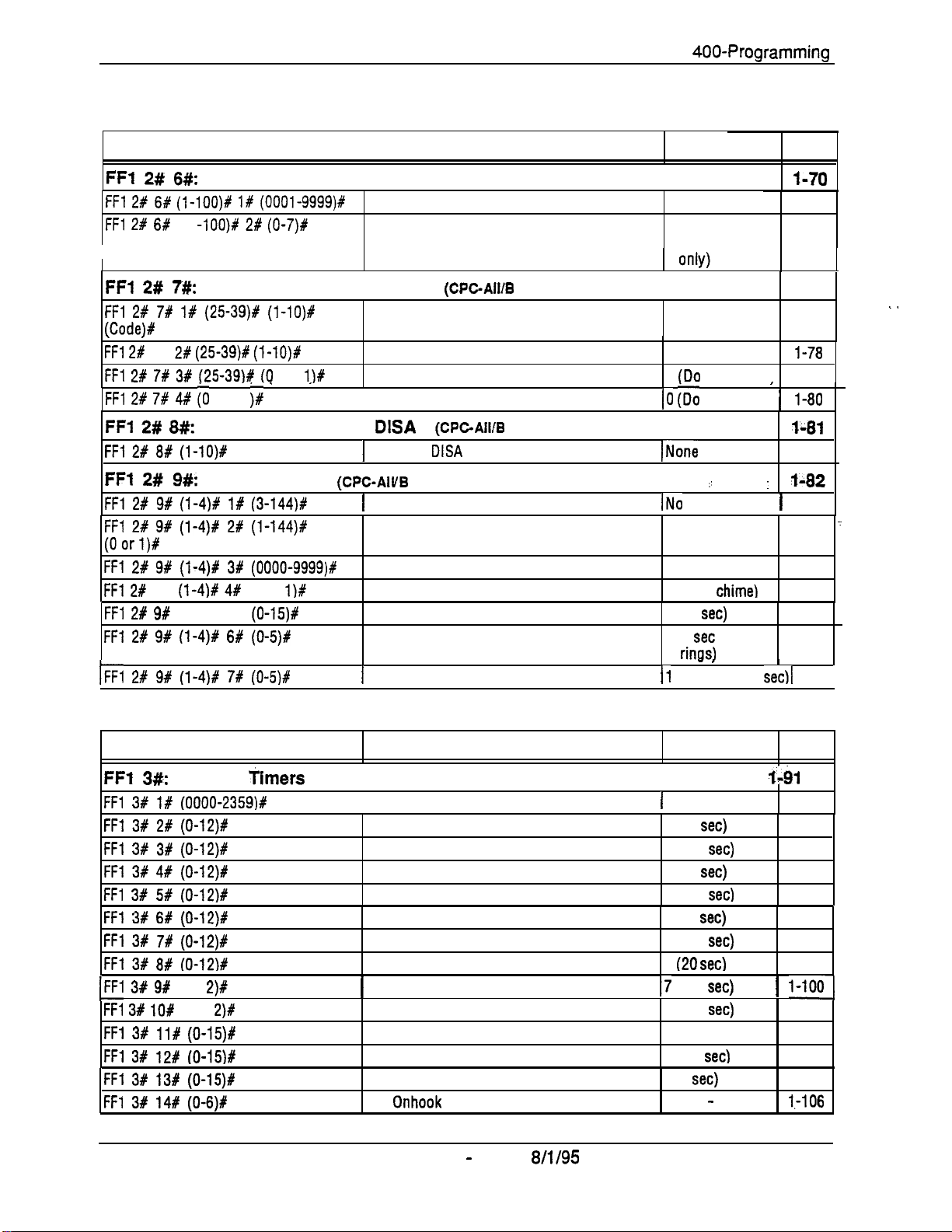
introduction to DBS Programming Section
400-Programming
Program Address
FFl
2#
6#:
Account Codes
FFl 2t 6# (l-1OO)P 1# (OOOl-9999)#
FFl 2# 6#
FFI 2# ?#:
FFl 2# 7# 1# (2539)# (I-lO)#
ICodeI#
,
FFl 2#
FFl 2# 7# 3# (2539)# (0
FFl 2# 7# 4# i0
FFl 2# 8#:
FFl 2# 8# (l-lO)#
FFt 2# 9#:
FFl 2# 9# (l-4)% l# (3-144)#
FFl 2# 9# (l-4)# 2# (1-144)X
(Oorl)#
FFl 2# 9# (i-4)# 3# (OOOO-9999)f
FFl 2#
FFl 2# 9#
FFl 2# 9# (l-4)# 6# (0-5)#
1~~1 2~ 9# (i-4)ry 7# (0-514~
(1
I
7% 2#
9%
(l-4)# 4#
(1-4)# 5%
-lOO)# 2# (0-7)#
Flexible Function Screens
(2539)# (l-lO)#
or 1 j#
(Text)# Flexible Function Screen Text
or
lI#
’
~
Caller ID Automatic
(PhoneNo.)#
Door Phones
(0 or
l)#
(O-15)8
Topic
Verified Forced Account Codes
Toll Restriction for Verified Forced Account
Codes
(CPGAIIB 6.0 or higher)
Flexible Function Screen Soft-Key Assignment
Flexible Function Screen Default
(Flexible Function Screens Default (All)
DISA
1
Automatic
(WC-AIVB
1
Door Phone Extensions
(CPGAIIIB
DISA
7.0
higher)
or
Door Phone Ring Assignments
Door Opener Access Code
Door Phone Tone Type
Door Phone Ring Timeout Timer
Door Phone Ring Pattern
1
Door Opener Relay Timer
6.1 or higher)
Callers
Default
None set
0 (TRS type 0 --
intercom calls
None
None
0
(Do
not default) 1-79
(0 ~DO
not default) 1l-80
INone
.’
. .
/No
assignment 1 1-82
0 (Do not ring)
9999
0 (Slow
3 (20
1 (4
I1
(Open for 4
set)
set
rinas)
- I
chime1
between
secll
Page
l-70
l-70
1-72
t-73
1-73
l-78
r
,
I-81
1-81
:
t-82
1-84
’
1-86
l-87
l-88
1-89 .
I
l-90 I
,’
Program Address
FFI 3#:
FFl 3# 1# (OOOO-2359)#
FFl 3# 2# (0-12)#
FFl 3# 3# (0-12)#
FFl 3# 4# (0-12)#
FFl 3# 5# (0-12)#
FFl 3# 6# (O-12)t
FFl 3# 7# (0-12)#
FFl 3# 8# (O-12)#
1~~1 3# 9#
FFl 38 lO#
FFl 3# ll# (0-15)#
FFl 3# 12# IO-15)f
FFl 3# 13# (0-15)P
FFl 3# 14# (O-6)8
Intro-l 2
System
(o-l
2)~
(O-1
2)#
Timers
Topic
[Automatic Night Mode Start Time
Attendant Hold Recall Timer for CO Calls
Extension Hold Recall Timer for CO Calls
Attendant Transfer Recall Timer for CO Calls
Extension Transfer Recall Timer for CO Calls
Attendant Hunt Group Recall Timer
Extension Hunt Group Recall Timer
Attendant Park Hold Recall Timer
1
Extension Park Hold Recall Timer
Attendant Call Reversion Timer for CO Calls
Unsupervised Conference Timer
Automatic Pause Timer
CO Flash Timer
SLT Onhook Flash Timer
DBS Manual - Issued
Technical Manuals Online! - http://www.tech-man.com
8/l/95
Default
1
Not set
1 (20
set)
7 (140
set)
1 (20
set)
7 (140
secl
1 (20
set)
7 (140
set)
1
(20 set)
17
(140
set)
9 (180
set)
2 (10 min)
7 (3.5
set)
9 (1
set)
4 (200 - 1500 ms)
DBS-70-400
Page
1-h
l-91
1-93
1-94
l-95
1-96
l-97
1-98
1-99
1 l-1001
l-101
l-102
l-103
l-104
I-106
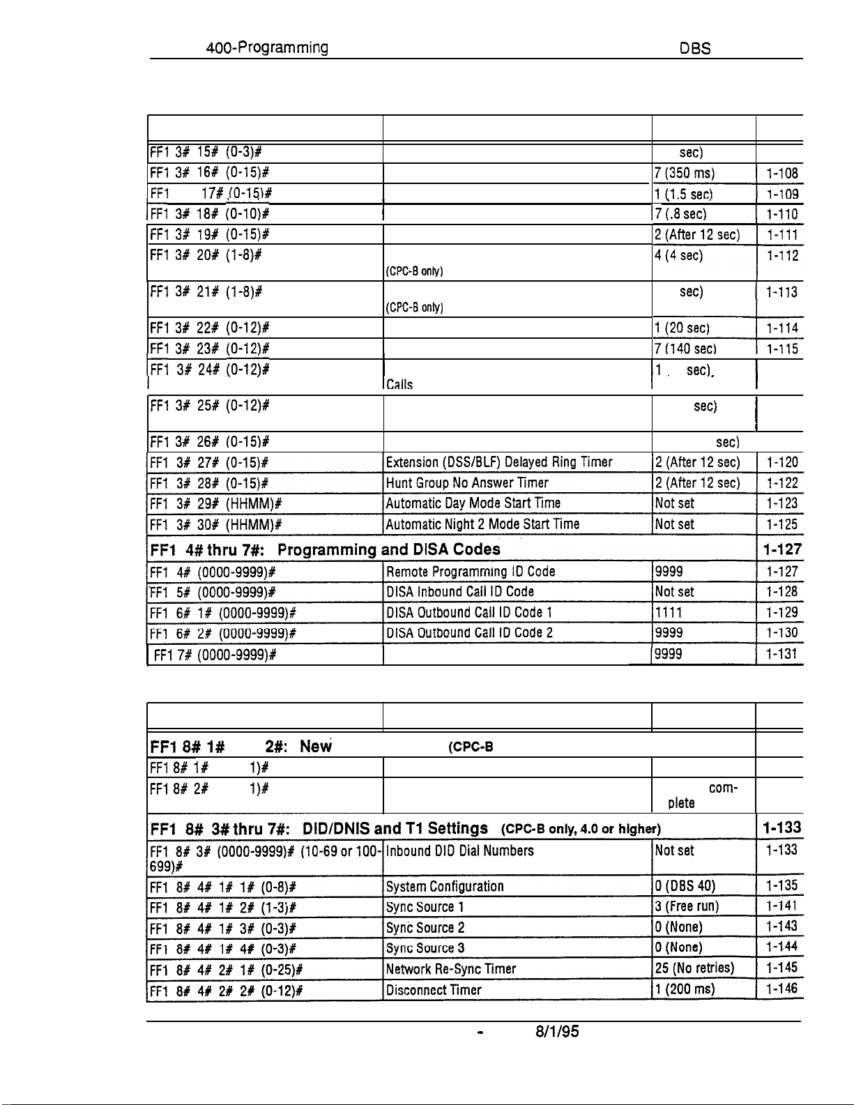
Section
Programming
400-Programming
Introduction to
DES
Program Address
FFl 3# 15# (O-3)#
FFl 38 16# (0-15)#
FF1
3X
17# (O-15M
l~Fl 3Rc la#
FFl 3f 19# (0-15)#
FFl 3# 20# (l -8)#
FFl 3# 21# (l-8)#
FFl 3P 22# (0-12)#
FFl 3# 23# fO-12)#
1~~13#
FFl 3# 25# (0-12)#
FFl 3# 26# (O-15)8
;o-lob
24# ;o-12k
. ,
Topic
CO Ring Cycle Detection Timer
Inbound Ring Cycle Expansion Timer
Dial Pause Timer
i
1
PBX Flash Timer
Call Forward-No Answer Timer
Outbound Ground Start Detection Timer
(CPC-8only)
Inbound Ground Start Detection Timer
(CPC-Bonly)
Attendant Hold Recall Timer for Intercom Calls
Extension Hold Recall Timer for Intercom Calls
I
1
Attendant Transfer
Extension Transfer Recall Timer for Intercom
Calls
CO Delayed Ring Timer
Recall
Timer
for Intercom
Default
1 (6
set)
I
*
I7 (.I3 set)
4 (4
set)
11
(20
set)
I‘
7 (140
set)
2 (After 12
’
set)
Page
l-107
I
1
1-116
I
l-117
/
I
1-118
1 FF~ 7# (oooo-9999)#
Program Address
FFl 8# I#
FF1 8# l#
FFl 8# 2#
DBS-70-400
and
(0 or
(0 or
2#:
l)#
l)#
Neti
Function Reset
1
ID Code for System Programming
Topic
@PC-B
New Function Reset
Confirm New Function Reset
DBS Manual - Issued
only, 4.0 or higher)
8/l/95
Default
0 (Do not reset)
0 (Do not
plete
com-
reset)
Page
l-132
l-132
1-132
Intro-l 3
Technical Manuals Online! - http://www.tech-man.com

Introduction to DBS Programming
Section
400-Programming
Intio-14
DBS Manual - Issued
Technical Manuals Online! - http://www.tech-man.com
8/l/95
D BS-70-400
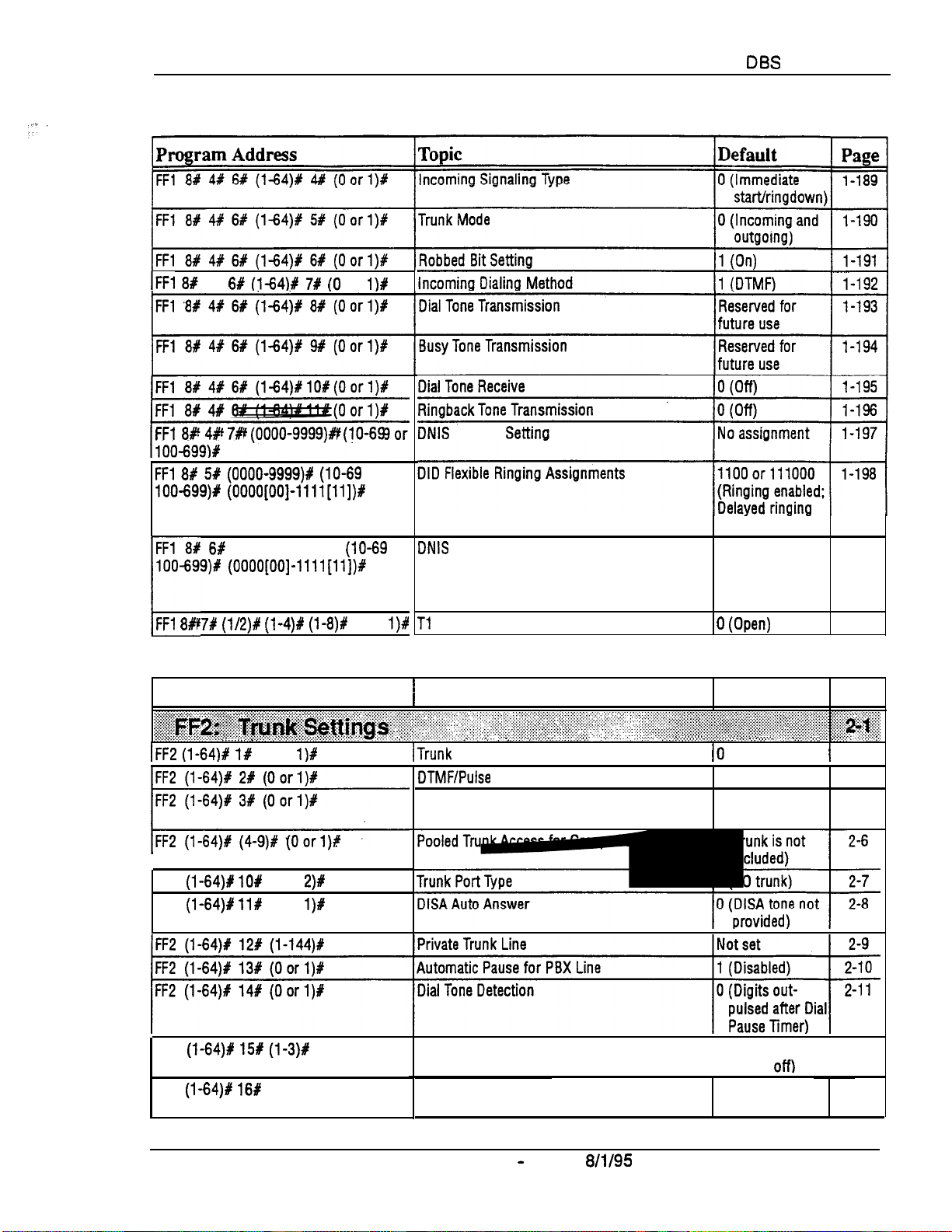
Section 400-Programming
1~~1 8f
48 6#
FFl 8# 4P 7# (0000-9999)# (lo-69
(i-64)1 7# (0
or
l)#
or
DNIS
Number
Settin
Introduction to
DBS
Programming
FFl 8P 51 (0000-9999)# (lo-69
100-699)# (0000[00]-llll[ll])P
r
6P (0000-9999)P
100-699)P (0000[00]-llll[ll])#
FFl 8# 7# (1/2)# (l-4)# (1-8)#
Program Address
~~~~~~~~~~B~~~~~~:~~~~~~~~~~~~~~~~~.~~~~~~~~~~~~~~~~~
IFF2 (l-64)# l#
FF2
FF2
,,...,(
(1-64)X lO#
(l-64)# ll#
;:.:... . . . . . . . .
,,
(0 or
(1 or
(0 or
l)#
2)#
l)#
or
DNIS
(lo-69
or
(0 or
l)#
‘...:.:..‘.:...:,‘:~:~,..
. . . .. .._.
Flexible Ringing Assignments
Tl
Trunk Closure
1
Topic
. . . . . . . . . . . . .
/Trunk Port Operation
,. ., ., _, .,.
DTMF/Pulse
Pooled Trunk
Pooled Trunk Access for Groups
.,
. . .
.:..
::.:.:.;...
.~.~.~.~.~.~.~.~.~.:
Dialing for Trunks
Access
._,.,.j,...,.,.
.:,:._ :,:: :,:,::::.,
. .
.,.,
for Group “9”
“81-86”
:
..,/,,,,,,,
..___..,,,
,. .:.:.::‘::.:::.:.:.:.~~;~~.~.~.~.:~::~:~~:.~:
,. .,...,_:
_,.,.,.,,,.,i.
disabled)
1100 or 111000
(Ringing enabled:
Delayed ringing
disabled)
0 (Own)
Default
:.......,.....
..,.,
. . . . . . . . . . . .
:,...,....
:.:.:.~.:.:.:.:.:.:.:.:.:.:.:.:.:.~.~
. . . . . . . . . . . .
.._.
. . . . . .
10
(In service)
0 (DTMF)
1 (Trunk is
included)
:.:.:.:.:.:.:,~:,:,:.~:.:..
,:.:. ~~ C.,.,.,.,.r,,
..,,. :..,I....
. .
.,.,. . . . . .
l-198
l-200
Page
:::i:i:I:i::.:~~:::‘:::~~:~:
:,:.:
. . . . .
.:.:.:.:.:
. .
. . . . . . . . . . . . .
:.
1
2-3
2-4
2-5
FF2
(1-64)X 15# (l-3)#
FF2
(l-64)P 16Y
DBS-70-400
(0 or 1)#
Outbound DTMF Signal Duration for Auto-Dialed 1 (75 ms on/
Dioits
Unsupervised Trunk Conference 0 (Disabled on
DBS Manual - Issued
Technical Manuals Online! - http://www.tech-man.com
8/l/95
I I
50 ms
off)
trunk)
2-l 2
2-13
Intro-l 5
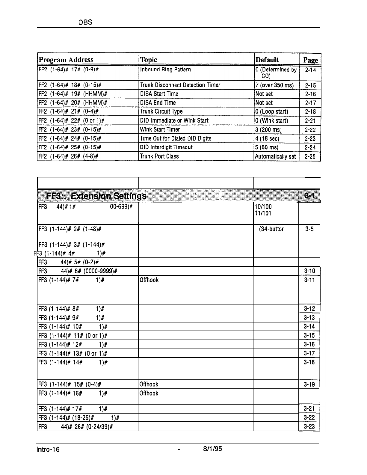
Introduction to
DBS
Programming
Section 400-Programming
Program Address
::::;:::;:::;;.:.:
:y.:.
. . . . . . . . . . .
..i..........~...~....
. . . . . . . . . . . .
. . . .
~ia:s~~~~~~~~~~~~~~,
. . . . . . . > . . . . . . . . . . . . . . . . . . . . . .
FF3
FF3 (I-144)f 2# (I-48)#
FF3 (l-144)# 3# (l-144)#
FF3 (l-144)# 4#
FF3
FF3
FF3 (l-144)f 7#
FF3 (l-144)# 8#
FF3 (l-144)+! 9#
FF3 (l-144)f lO#
FF3 (l-144)# ll# (Oorl)#
FF3 (I-144)# 12#
FF3 (I-144)t 135 (Oar I)#
FF3 (I-144)# 14#
FF3 (l-144)# 15# (O-4)#
FF3 (i-144)# 16f
FF3 (I-144)# 17#
FF3 (l-144)P (Ia-25)#
FF3
5 ::.
.:,.:.
(l-l
44)k: I#
(1-l
44)# 5# (O-2)#
(l-l
44)# 6# (OOOO-9999)#
(l-l
44)# 26W (0-24/39)#
:...~:.:.:i.:.~::.::.:;:~.~:~::::::::.~~~:~;,:.::‘.~~:~:~:
. . . . . . . .
.._............
,...........~....,.......~..... . . . . . . . . . . .
(1 O-69 or 1
(0 or
(0 or
(0 or
(0 or
(Oor
(0 or
(Oor
(Oor
(0 or
I)#
I)#
l)#
l)#
l)#
l)#
I)#
l)#
l)#
(0 or
OO-699)#
l)#
Topic
.,. : ‘..: :.,,:: :.:.:..:
. .
,. ,.
..:. :.:.. :...
. ..:
. . . :, .:
~~~~~~~~ili:;:.:i:i:;:‘.ii.:::.i::i~~:,
. . . .
Terminal Type
Call Waiting/OHVA
Auto Pickup (Ringing Line)
Station Message Detail Recorder (SMDR)
Report
Offhook Signal Volume
Offhook Signal Pattern 0 (Repeated tone
PSD Name Display on Large-Sized LCD Phones 0 (5 PSD names)
Page Group Extensions 0 (None)
Display When Idle
_...
Extension Numbers .
EM/24 Port Assignment
Forced Least Cost Routing
Forced Account Codes
Extension Lockout Code
Offhook Signal (CO)
Busy Override Send
Busy Override Receive
Prime Line Pickup
Unsupervised Conference
;.
,::~~~~~~~~
Default
.A..
lO/lOO
(Port 1)
1lM0l
(Port 2)
. . .
etc.
4
(34-button
phone)
No assignment 3-7
0 (Disabled) 3-8
0 (Voluntary)
Not set
0 (Disabled)
1 (Enabled for
Primary Atten-
dant only)
1 (Enabled)
0 (Disabled)
1 (Enabled)
0 (Disabled)
1 (Enabled)
0 (Disabled)
1 (Extension is
included in
SMDR report)
2 (Mid-level)
burst)
0 (Prev. menu)
Page
. . . . . . . . . . . . . . . . . . . . . . . . . . . . . . . . . . . . . . . . . . . .
key
. . . . . . . . .
.
3-3
3-5
3-9
3-20
I
Intio-16
DBS Manual - Issued
Technical Manuals Online! - http://www.tech-man.com
8/l/95
D BS-70-400
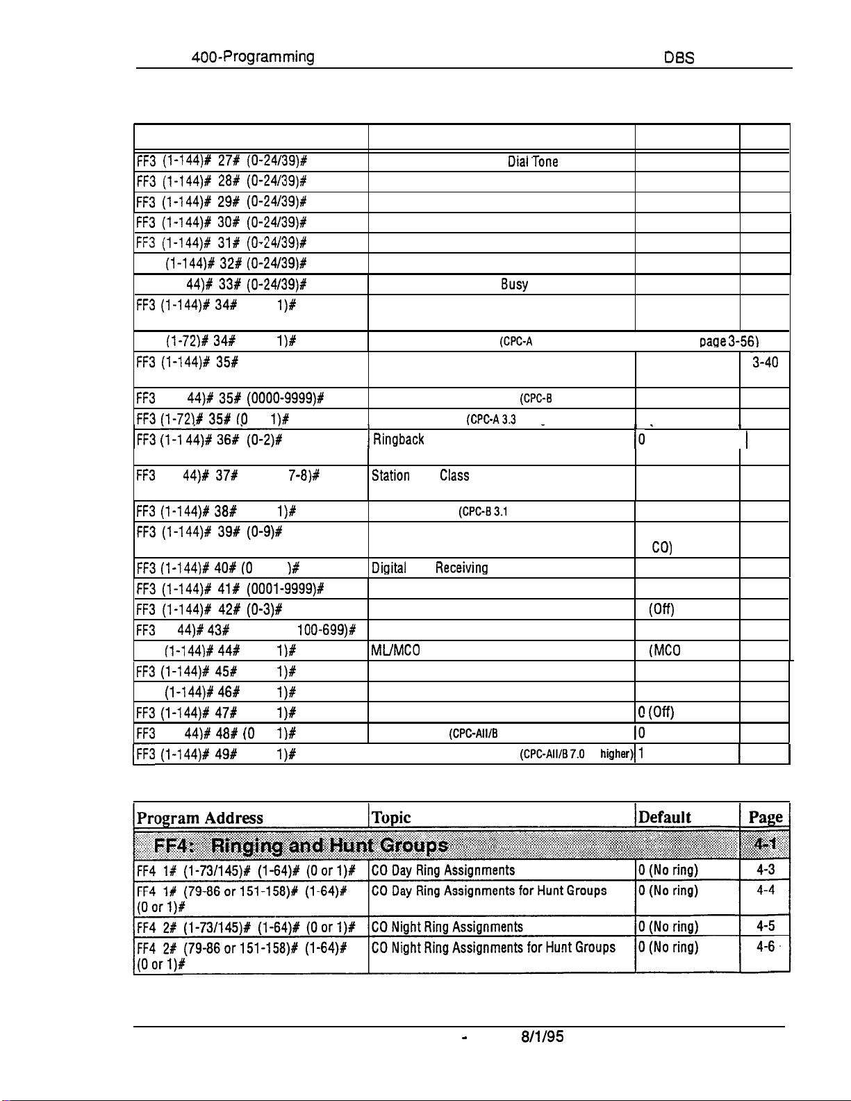
Section
400-Programming
Introduction to
DBS
Programming
Program Address
FF3 (l-144)# 27# (0-24/39)#
FF3 (l-144)# 28# (0-24/39)#
FF3 (l-144)# 29# (0-24/39)#
FF3 (l-144)# 30t (0-24/39)#
FF3 (l-144)P 31# (O-24/39)8
FF3
(l-144)# 32# (0-24/39)#
FF3 (l-l
FF3 (l-144)# 34#
FF3
FF3 (l-144)# 35#
FF3
FF3 (l-72)# 35# (0
FF3 (l-1 4b)# 36#‘ (0-2)c
FF3
FF3 (l-144)# 38#
FF3 (l-144)8 39# (0-9)#
FF3 (l-144)# 40# (0
FF3 (l-144)# 418 (OOOl-9999)#
FF3 (l-144)# 42# (0-3)#
FF3
FF3
FF3 (l-144)# 456
FF3
FF3 (l-144)# 47#
FF3
(FF3 (l-144)# 49#
44)# 33# (0-24/39)#
(0 or
(l-72)# 34#
(0 or
(0-8)#
(l-1
44)# 35# (0000-9999)#
(l-l
44)# 37#
(l-2 or
(0 or
(l-l
44)# 43#
(l-144)# 44#
(1 O-69 or
(0 or
(0 or
(l-144)# 46#
(0 or
(0 or
(1-l
44)# 48# (0
(0 or
or
or 1
or
l)#
l)#
l)#
7-8)#
l)#
)#
l OO-699)#
l)#
l)#
l)#
1)#
l)#
l)#
Topic
Display During Intercom
Display When Calling an Extension
Display When Accessing CO Dial Tone
Display When Conversing on a CO Trunk
Display When Receiving a Page
Display After Receiving a Call Waiting Tone
Display When Dialing a
Extension Directory Display
(CPC-Ail; CPC-B 2.0
VAU Port Assignment
Extension Class of Service Assignment
(CPC-All; CPC-B 3.1 or higher)
Inbound DID Dial Numbers
AEC Disconnect
I
1
Ringback Tone From ML Keys
Busy
or higher)
@PC-A
(CPGA3.3
Dial’Tone
Extension
3.3 or higher)
(cPc-B
or higher)
_
2.0 only)
Default
0 (Prev. menu)
0 (Prev. menu)
0 (Prev. menu)
0 (Prev. menu)
0 (Prev. menu)
0 (Prev. menu)
0 (Prev. menu)
0 (5 names)
(see
paQe 3-56)
0 (Class 0; all
features allowed)
No assignment
0 (Disabled)
I *
10
(Ringback, then 1 3-42
busy tone)
Station
Port
CkiSS
(CPC-84.0 or higher)
Automatically
assianed
SLT Hookflash
Extension Ring Pattern
(CPGB3.1
or higher)
0 (Broker’s hold)
0 (Determined by 3-46
CO)
DiQitaf
SLT
ReceivinQ
Auto Set Relocation Code
Permanent Call Forward Type
Permanent Call Forward Extension
ML/MC0
Separation
Volume
0 (Normal)
Not set 3-49
cl (Off)
No assignment
0
(MC0
keys) 3-53
VAU Hunting Priority 0 (No priority)
AEC Disconnect 0 (Disabled) 3-55
VAU Port Assignment
Hot Dial Pad
(CPC-All/B
7.0
[Auto-Redial on Extensions
or higher)
(CPC-AIuB7.0
or
IO
higher)/1
0 (Off)
(Disabled) 3-57
(Enabled)
Page
3-25
3-27
3-29
3-31
3-33
3-35
3-37
3-39
3-40
3-41
3-41
I
3-43
3-45
3-48
3-51
3-52
3-54
3-56
1
3-58
1
DBS-70-400
DBS Manual - Issued
Technical Manuals Online! - http://www.tech-man.com
8/l/95
Intro-l 7
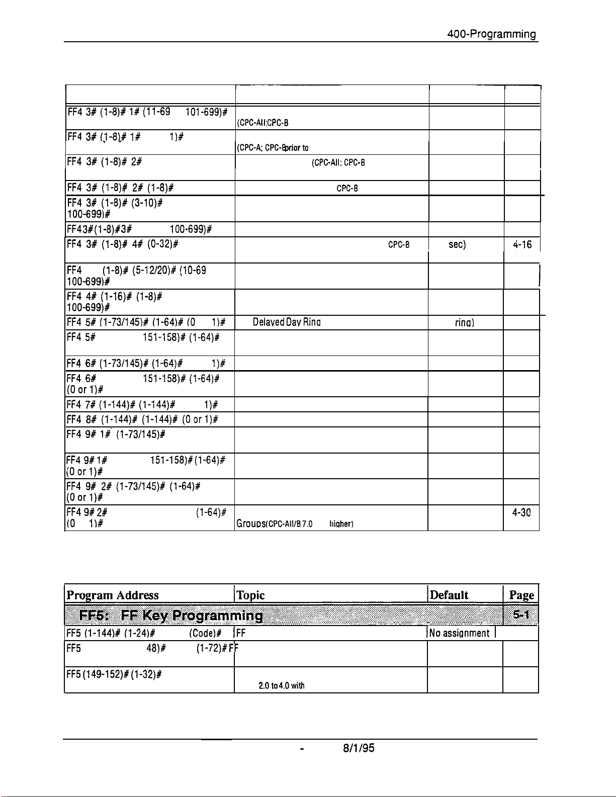
introduction to DBS Programming Section
400-Programming
Program Address
FF4 3# (l-8)# I# (11-69
FF4 3# (I-8)P I#
. ,
FF4 3# (l-8)# 2#
FF4 3# (1-8)# 2# (l-8)1
FF4 3# (l-8)# (3-lO)#
l OO-699)#
FF4
3#
(I-8)# 3#
(1 O-69 or l OO-699)# Transfer Extension
FF4 3# (l-S)# 4# (0-32)#
FF4
3%
(l-8)P (5-12/20)# (lo-69
100-699)#
FF4 4# (1-16)# (l-8)#
IOO-699)#
FF4 5# (l-73/145)# (l-64)% (0
FF4 5#
(79-86 or
(Oorl)#
FF4 6# (l-73/145)# (l-64)#
FF4 6#
(79-86 or
(Oorl)#
FF4 7# (l-144)# (l-144)#
FF4 8# (l-144)# (1-144)f (Oorl)#
FF4 9# l# (l-73/145)#
(Oorl)#
FF4 9# l#
(79-86 or
(Oorl)#
FF4 9# 2# (1-73/145)# (l-64)#
(Oorl)#
FF4 9# 2#
(0
or
(79-86 or 151-158)X
1)#
or
101-699)#
(0 or
l)#
(0-2)#
(IO-690r
(IO-690r
or
151-158)# (l-64)#
(0 or
151-158)# (l-64)#
(0 or
(l-64)f
151-158)# (i-64),+
(l-64)$
Topic
Hunt Group Pilot Numbers
(CPC-All: CPC-8
Terminal/Circular Hunt Groups
(CPC-A;CPC-B priorto
Hunt Group Type
Call Next Hunt Group
Hunt Group Members
Hunt Group Transfer Timer
higher)
or
Hunt Group Members
Call Coverage Group Members
CO
1)P
Delaved Dav Rino
CO Delayed Day Ring Assignments for Hunt
Groups
l)#
CO Delayed Night Ring Assignments
CO Delayed Night Ring Assignments for Hunt
Groups
l)#
Extension Ring Table
Extension Delayed Ring Table
CO Night 2 Ring Assignments
(CPC-All/B 7.0 or higher)
CO Night 2 Ring Assignments for Hunt Groups 0 (No ring)
(CPC-All/B 7.0 or higher)
CO Delayed Night 2 Ring Assignments
(CPC-All/B 7.0 or higher)
CO Delayed Night 2 Ring Assignments for Hunt 0 (No ring)
Grouos
2.0 or higher)
2.0)
(CPC-Ak CPC-B 2.0 or higher)
(CPC-A;
(CPC-A; CPC-B prior to 2.0)
(CPC-All; CPC-B 2.0 or higher)
CPC-I3
prior to 2.0)
(CPC-All; CPC-B 2.0 or
(CPC-All; CPC-B 2.0 or higher) No assignment
Assionments
(CPC-AIVB7.0
or
higher)
Default
Page
No assignment 4-7
0 (Terminal
4-9
‘hunting)
0 (Terminal
4-11
hunting)
No assignment
No assignment
000
2 (2
set)
4-13
4-14
4-15
(i-16
4-l 7
No assignment
0 (No
rina)
0 (No ring)
0 (No ring)
0 (No ring)
0 (No ring)
0 (No ring)
0 (No ring)
4-l 8
4-20
4-21
4-22
4-23
4-25
4-26
4-27
4-28
0 (No ring)
4-29
4-3c
I
I
.,.,..,_,_,...,.,.,.,.,.,.,.,.,.,.,.,.,..i, ..,..:...............,...,.,.,.,...,..,.,
FF5 (l-144)# (l-24)#
FF5
(73-76 or 145-l
CONF
48)#
CONF
(Code)#
(1-72)P FF
(FF
Kev Assignments for Extensions
Key Assignments for DSS Consoles
(Code)#
FF5 (149-152)# (1-32)#
CONF (Code)# Attendant Feature Package Key Assignments
CPC-B
2.0to 4.Owith
AFP
intro-l 8 DBS Manual - Issued
Technical Manuals Online! - http://www.tech-man.com
8/l/95
.,., .,. ., .,.., ,.
,.,_,. ,.,..,
., ,.,.,.,.,.,.,.,. ,_,.,.,,,.,.,. .,.,,,.,.
INoassionment 1
No assignment 5-8
No assignment 5-10
. . .
5-3
D BS-70-400
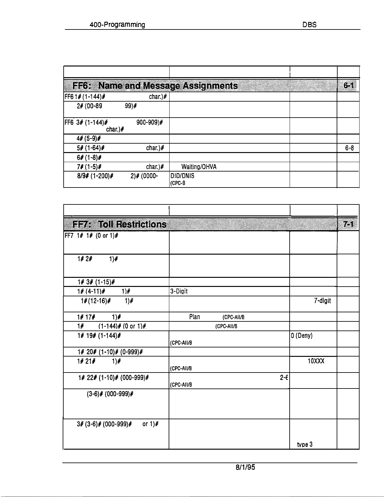
Section
400-Programming
Introduction to
DBS
Programming
Program Address
FF6 1# (l-144)#
FF6 21
(00-89
(up to 16 char.)%
FF6 3# (l-144)P
CONF (up to 16
FF6 4#
FF6 51
FF6 6#
FF6 7#
FF6
(59)P
(l-64)P
(I-@#
(l-5)P
8/9# (l-200)#
9999)R (up to 6 char.)#
CONF (up to 10
or 000-l
(90-99 or
char.)#
CONF (up to 15 char.)%
CONF (up to 6
CONF (up to 10 char.)#
CONF (up to 15
(1 or
Program Address
FF7 1P 21 (0 or
FF7 l# 3#
FF7 l#
FF7 If
FF7 l#
(4-ll)#
(12-16)#
17#
FF7 l# 18X
FF7 l#
FF7 l#
FF7 l#
FF7 l#
FF7 2%
FF7 3#
19# (l-144)#
20# (l-lO)# (0-999)#
21Y
225 (l-lO)# (000-999)#
(3-6)# (000-999)P
(3-6)# (000-999)#
l)#
(l-15)#
(0 or
l)#
(0 or
(0 or
I)#
(l-144)# (Oar l)#.
(Oor 1)#
(0 or
l)#
99)#
CONF
900-909)#
2)# (OOOO-
l)#
(0 or 1)#
(0
orl)#
char.)#
char.)#
char.)#
Topic
Extension Name
System Speed Dial Names
Personal Speed Dial Names
Absence Messages
Trunk Name Assignment
Hunt Group Name Assignment
Call Waiting/OHVA Text Reply
DID/DNIS Text Name Assignment
(CPM
5.0 or higher)
1
Topic
International Calling For TRS Types 3-6
DTMF Signaling During Incoming Calls for TRS
Types O-6
Maximum Dialed Digits For TRS Types 3-6
3-Digit
Toll Restriction For TRS Types 2-6
7-Digit Toll Restriction For TRS Types 2-6
Dialing
Operator Access
international Calling on Extensions
(CPC-All/B
Country Code Table
Equal Access Code Format
(CPC-All/B
Office Code Restriction Table For TRS Types
(CPC-All/B
Area Code Table For TRS Types 3-6
Office Code Table For TRS Types 3-6
Plan
Switch
6.0 or higher)
6.0 or higher)
6.0 or higher)
(CPC-AWE
(CPC-All/B
(CPC-All/B 6.0 or higher)
6.0 or higher)
6.0 or higher)
2-6
1
Default
Page
No assignment 6-3
No assignment 6-4
No assignment 6-5
No assignment 6-6
No assignment
No assignment 6-9
No assignment
No assignment
Default
6-l 0
6-l 1
Page
~~~~:
1..
0 (Deny/Check
Country Code
Table)
1 (Enable DTMF
signaling during
incoming calls)
l * (Unlimited)
0 (Allow)
1 (Check
7-digit
table)
0 (Old dial plan)
0 (Deny)
0 (Dew)
No assignment
0 (Old
10XxX
format)
No assignment
0 (Allow) for TRS
types5and
1 (Deny) for TRS
types3and 4
0 (Allow) for TRS
types 4-6
1 (Deny) for TRS
tvoe3
7-5
7-6
7-7
7-8
7-9
7-l 0
7-l 1
7-l 2
7-13
7-14
7-l 5
7-l 6
6
7-l 7
S-6
DBS
DBS-70-400
Manual- Issued
Technical Manuals Online! - http://www.tech-man.com
8/l/95
.
Intro-19
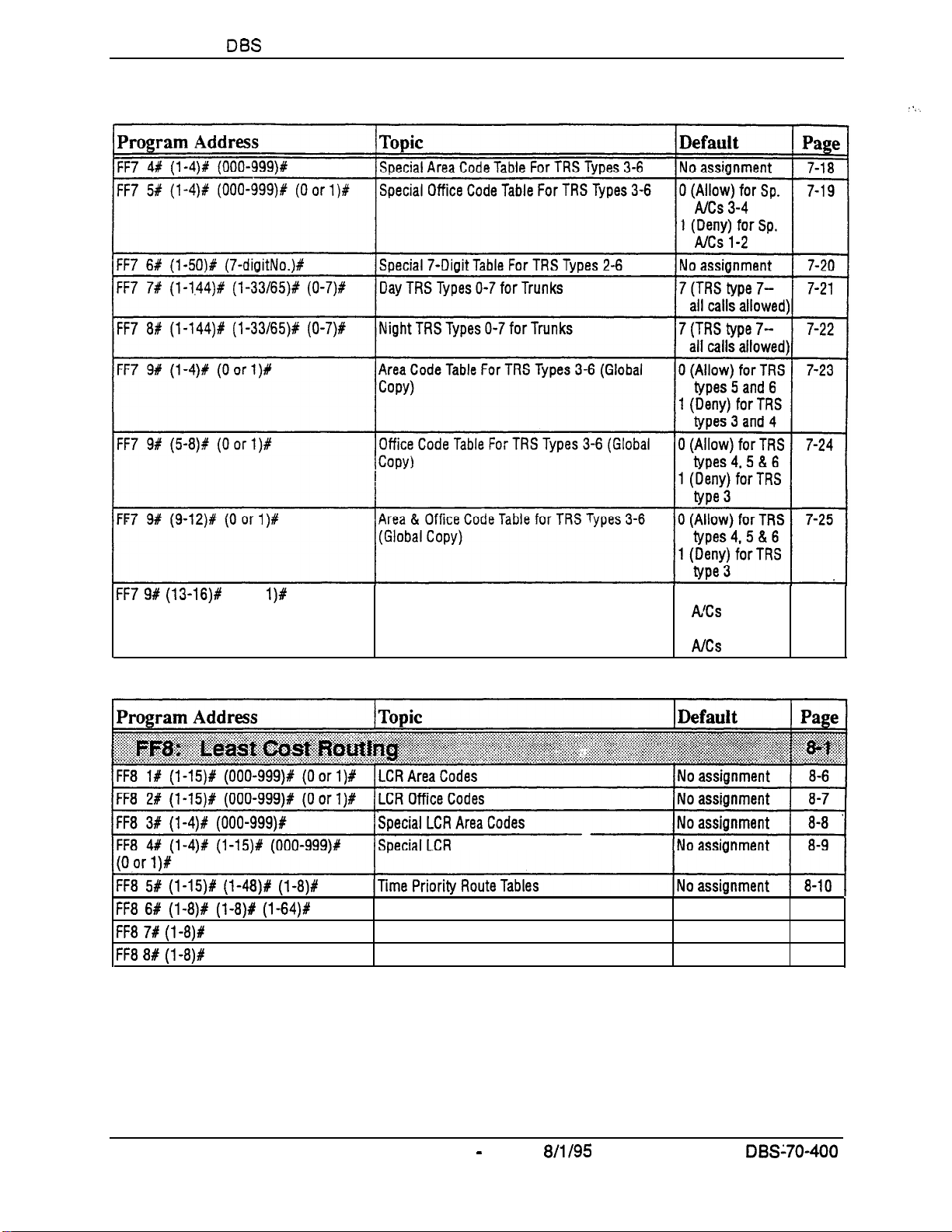
Introduction to
DBS
Programming
Section 400-Programming
K-7 9# (13-16)#
FF85#
FF8 6# (l-8)# (l-8)# (l-64)#
FF8 7# (l-8)P
FF8 8# (l-8)#
(l-15)# (I-48)# (l-8)#
(0 or
l)#
(up to 16 digits)#
(up to 16 digits)#
Special Office Code Table For TRS Types 3-6
(Global Copy) .
Off ice
Code Tables
LCR Trunk Groups No assignment 8-12
LCR Delete Tables
LCR Add Tables
0 (Allow) for Sp.
AlCs 3 and 4
1 (Deny) for Sp.
A/Cs 1 and 2
No assignment 8-13
No assignment 8-14
7-26
Intro-20
DBS Manual - Issued
Technical Manuals Online! - http://www.tech-man.com
8/l/95
.
DBS’70-400
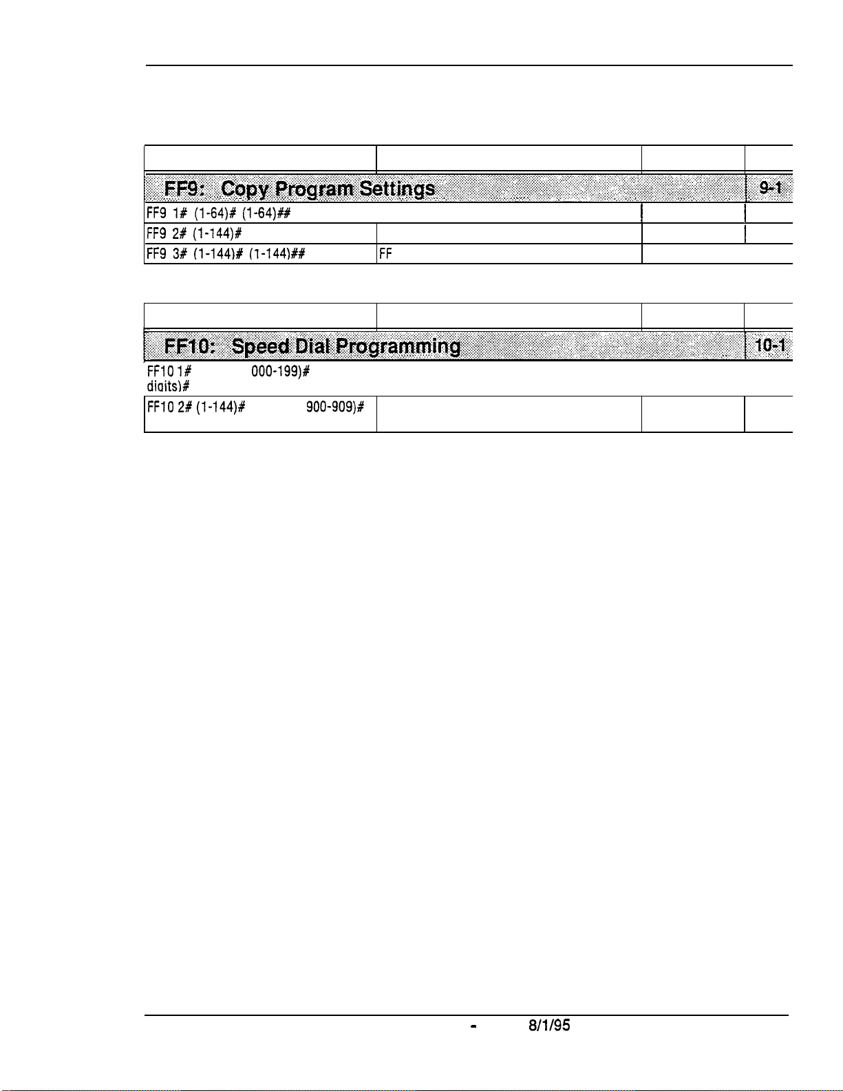
Section 400-Programming
I
Introduction to DBS Programming
Program Address
‘. .‘.‘.A .....
. . . . . . .
..i.. .:+.:.:yy..:::.:.:
. . . . i.\:
:.:.:.:. ~~ .:,:...:.:.:.::
:~~~~~~~:~~~~~a~~~~~~~~~~~~.~~~~~~~~~~~~~~~~~~~~~~~~~~~~~~~l~~~~~~~
. .
.,.
. . .
.,.,.,.,...
. . . . . . . . . . . .
.:.:. .:...: .,.,.,.
. . .
.(. ., .:
.:.:. .,., ..:.:.;,::.:.:.
FF9 1# (l-64)P (l-64)##
FF9 2# (l-144)#
FF9 3# (l-144)# (1-144)##
Program Address
.,.
:‘.
..,. ::.::.:.:..y:,:.:.: . . . . . . . . . . . .:.
;..iia~~~~~~~~~.a~~~~~~~~~,~~~~~~~~~~~~~~~~~~~~~~~~~~~~~~~~~~~~~~~~~~~
FFlO l#
diaitslf
FFlO 2# (l-144)f
(up to 16 digits)#
(00-89 or
(I-144)ft
., ._ ,. ,.
:.:...:.:.:.>>:..:.>
..,:; ,::.:.
.:.:.:.I:.:.‘,
:
000-199)#
(90-99 or
:.:.:::>>::::;
.
..,,..,,.,.
..A..
,.;::.:
:.j :.~:.:::::::...:::.~:‘~.‘-~:.:.~::::.:.~::;~~~:~::::~..
(up to 16 System Speed Dial Numbers
900-909)#
Topic
;>;;:. ‘.:~i$~~~::‘.‘.::
. . .
.::; 5- ..<I :., ~,.i.i.i.:,::,ii:ii~~:~:~:~~~~~::::~~::.~~~~~~:~.~::~::~~:~~:~:~:~~~:::.ii:::::,
., ., .,... .,
. . . .
y:.::.
/Trunk Copy
Extension Copy
FF
. . . . . . .:
.,... :..:
Key COPY
. . . . . .
Topic
. . .
.,.::.:.:.,.:.
.,:.......
. . . . . . .
. . . . . . . . . . . . ._
::.::l.::::.:i,:-j:-;::::::~
.,....., .. . . .
. . .
,..,........
I
Personal Speed Dial Numbers
;
:...y c :::.,::::
‘.’:.‘...:
. .. ..\.
.
‘.‘:‘.‘.‘.“:‘::.:i::
.,.,... ,.,. .,.,. .,. ., ._.
. . . .
., ., ., .,
1
Not set
Not set
Not set
Default Page
~~~~~.~.~.~~~.~.,~~.~
,.,.,...
Default Page
.,.,.,., ,.,.,.,:
.,.,...
.
...:...:: :::+, .:. ‘.
. . . .
. . . . . . . .
. . . . . . . . . . . . . . . . . . .
Not set
I
Not set
. .
2.. .::.:.: .::.
.:, j..: ,::..,..: 3’,:,:::
:.j:;~::::i::::::i.i:::.:. :::;
.,_.
,. .,
. . .
.,, :.
,.. ;. .‘..-:;
. . : (. y..:., .J,
,...
. ,.:+ .:.::::j:j
. .
/
9-3
1
9-4
i 9-5
. . . .
.,....
. . . . .
. . . . . . . .
‘.’ :.
10-3
10-5
DBS-70-400
Technical Manuals Online! - http://www.tech-man.com
DBS Manual - Issued
8/l/95
Intro-21

1. System Programming
(FFl)
This chapter describes DBS system settings using programming key
This chapter covers the following
F’Fl
Address
FFl l#
FFl 2# l#
FFl 2# 2# Serial Port Parameters (TTY Settings)
FFl 2# 3# PBX Settings
FFl 2# 4##
FFl 2# 5#
FFl 2# 6#
FFl 2# 7#
FF1 2# 8#
FF1 2# 9#
FFl 3#
FFl 4##thru7# Programming and DISA Codes
Topic
Date and Time Settings
General System Settings
External (UNA) Relay Control
Class of Service
Account Codes
Flexible Function Screens
Caller ID Automatic DISA
Door Phones
System Timers
FFl
addresses:
(CPC-AII/B
7.0 or higher)
FFl.
Page
l-3
==i
l-5
1-53
-I
l-68
l-70 I
l-73
1-81
I
I
1
FFl 8# l#
FFl 8# 3#
and
thru
2#
New Function Reset
7# DlD/DNTS
and Tl Settings (CPC-B
only)
1-133
1
DBS-70-400 DBS Manual - Issued
Technical Manuals Online! - http://www.tech-man.com
8/t/95
Page l-l

Page l-2
DBS Manual - Issued
Technical Manuals Online! - http://www.tech-man.com
8/l/95
DBS-70-400
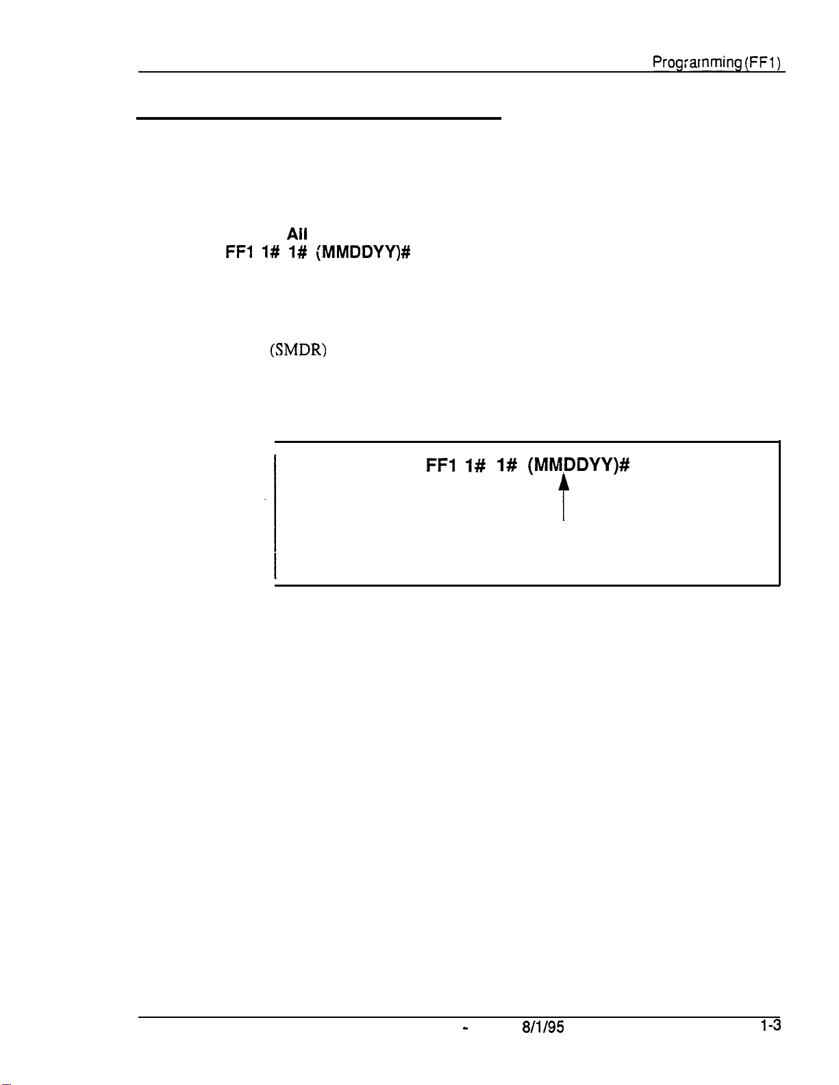
Section
400-Programming
Date and Time Settings
Day/Date Setting
Software Version:
Address:
FFl l# l# (MMDDYY)#
Ail
Versions
Chapter 1. System
Prog;arnming (FFl)
Description
Programming
This program sets the date in the DBS system clock.
The day and date are printed on the Station Message Detail Recording
(SMDRj
correct date settings. Proper operation of peripheral equipment may also
depend on correct date settings.
printout Proper LCR (Least Cost Routing) operation depends on
I
FFl
1# 1# (MM.DDYY)#
t
Month, day, and year in numeric format
(for example, January 1.1995 would be
entered as 010193.
DBS-70-400
Technical Manuals Online! - http://www.tech-man.com
DBS Manual - Issued
8/l/95
Page
l-3

Chapter 1. System Programming
(FFl)
Time Setting
Software Version: All Versions
Address:
FFl 1# 2#
(HHMM)#
Section 400-Programming
Description
Programming
This program sets the time in the DBS system clock. The time appears on key
phones that have LCDs. The time is also recorded in SMDR call records.
Note:
Routing) operation.
Correct time settings are necessary for proper LCR (Least Cost
I
Time setting in 24-hour format
(for example, 3:00 pm would be
entered as 1500).
Page l-4
Technical Manuals Online! - http://www.tech-man.com
DBS Manual - Issued
8/l/95
DBS-70-46?j

Section 400-Programming
Chapter 1. System Programming
General System Settings
Call Duration Display
Software Version: All Versions
Address:
FFl 2# 1# l#
(0 or
l)#
(FFl)
Description
This program determines whether
telephones with LCDs. By default, call duration will display.
Programming
Related Programming
SMDR Display Start Timer for CO Calls:
LCD Timer for Caller ID:
Notes
No Interaction With
record generation.
FFl 2# 1#
FFl 2# l# 38#
SMDR
Records.
call
duration will be displayed on
l#
(0 or
O=Call
l=Call
duration is not displayed.
duration is displayed.
(0, 1 or
This setting does not affect SMDR
t
FFl 2#
l)#
1# 2# (0, 1 or
2)#
2)#
Timing
Caller
the delay before call duration is displayed, so that Caller ID information can
appear first. In versions prior to 6.1, the
CO
D&-70-400
Technical Manuals Online! - http://www.tech-man.com
of
Call Duration Display.
ID,
the
LCD Timer for Caller
Calls
(see next address) controls the delay.
DBS Manual - issued
In
CPC-AH/B
ID address
SMDR Display Start Timer for
8/l/95
Version 6.1 or higher using
(FF12# l# 38#)
determines
Page l-5

Chapter 1. System Programming
(FFl)
Section
400-Programming
SMDR Display Start Timer for CO
Software Version: All Versions
Address:
Description
Programming
FFl 2# l# 2#
This address determines the delay between the start of a call and the
beginning of the SMDR record (5 seconds by default). In CPC-AII/B
versions prior to
displayed on LCD phones.
l
For Incoming Calls:
answers an incoming trunk
ends, the system will not generate an SMDR record for the call.
l
For Outgoing Calls:
the outgoing phone number. This allows time for the CO to connect the
call, or the called party to answer, before beginning the SMDR record.
(0, 1, or
6:1,
2)#
it also controls the delay before call duration is
An incoming call starts when the extension user
calI.
If the user hangs up before the Timer
An outgoing call starts after the extension user dials
FFl 2# I# 2#
O=
SMDR record begins after 5 seconds.
l=
SMDR record begins after 16 seconds.
2=
SMDR record begins after 30 seconds.
Ca!ls
(0, 1, or
+
2)#
Related Programming
Call Duration Display:
SMDR Communications Parameters:
SMDR Report (including the extension in):
Notes
Caller ID Interaction.
the SMDR Display Start Timer does not control when call duration starts
displaying on LCD phones. Instead, the
controls when the display begins.
Settings In Older DBS Versions.
3.1, the SMDR Display Start Timer has only two settings -- “0” (16 seconds)
or “1” (30 seconds).
Page l-6
Technical Manuals Online! - http://www.tech-man.com
DBS Manual - Issued
FFl 2# l# l#
In
CPC-AII/B
(0 or
l)#
FFl 2# 2# (l#
FF3
(ExtPort)# l#
thru
9#)
(0 or
l)#
Version 6.1 or higher using Caller ID,
LCD Timer for Caller ID
address
In CPC-A and CPC-B versions prior to
8/I/95
DBS-70-400 .

Section 400-Programming
Chapter 1. System Programming
Least Cost Routing (LCR) Access
Software Version: All Versions
Address:
FFI 2# l# 3#
(0 or
l)#
(FFI)
Description
This program specifies whether Least Cost Routing (LCR) is used when
is dialed to make an outside call.
Prdgramming
Related Programming
Forced Least Cost Routing: FF3
LCR Settings: all
Notes
Restriction With Call Forward-Outside Feature (in CPC-AII and CPC-B
Version
feature. If LCR is activated (the above address is set to “l”), extensions set to
Call Forward-Outside must
used). See
FFl 2# l# 3#
0=“9”
1=“9’*
(ExtPort)# 4#
FF8
programs
7.0
and above).
Section 700~Feature Operation
LCR will not work with the Call Forward-Outside
use
trunk groups l-6 (trunk group “9” cannot be
(0,or I)#
indicates a pooled-trunk call.
indicates an LCR call.
(0 or
for more information.
l)#
“9”
I
I
Required Hardware Setting.
See Section
FCC
Regktration. If strap S 1 is cut, a different FCC registration number
300~Installation
should be used to identify the DBS
for the DBS as a PBX system (Sl is cut), and one for the DBS as a KSU (Sl
is not cut) -- are printed on a label in the main cabinet. See
Installation
DBS-70-400
Technical Manuals Online! - http://www.tech-man.com
for more information.
DBS Manual - Issued
Cut strap S 1 on the CPC card to enable LCR.
for instructions.
syste,m.
Both registration numbers -- one
8/l/95
Section
.
300-
Page
1-7

Chapter 1. System Programming
Page 1-8
DBS Manual
-
Issued
8/l/95
D&-70-400
(FFl)
Section
400-Programming
Override
Software Version: All Versions
Address:
Description
Toll
Restriction With SSD Numbers
FFl 2# l# 4#
This address allows you to set a range of System Speed Dial (SSD) codes that
will override Toll Restriction Service (TRS) types 2-6.
The number entered in this address is the lower boundary for SSD codes that
will override TRS. In other words, all SSD numbers higher than the one
entered will also override TRS types 2-6.
(SSD)#
Programming
To set a range of SSD numbers to override TRS settings
(enter the lowest SSD code in the range) . . .
FFl 2# l# 4#
(all
(00-89
Lowest
SSDs
SSD Code that will override TRS
above this number will also override TRS)
or
0001199)#
+
To reset to the default value . . .
By default, SSD,numbers do not override TRS types 2-6. To reset to default:
I
Related Programming
TRS Settings: all FF7 programs
SSD Numbers:
Notes
SLT Audio
executed on an SLT phone, there is a
to the receiver.
Delay.
OO-89=SSD
OOO-199=SSD
FFl 2# l#
FFlO l# (SSD)# (PhoneNo.)#
If “Override Toll Restriction
code range for CPC-A (all versions),
CPC-AII and CPC-B versions prior to 7.0
code range for
Version 7.0 or higher
4#
CONF ON/OFF
15-second
delay before audio is passed
CPC-AI1
With
SSD Numbers” is
and CPC-B
I
Technical Manuals Online! - http://www.tech-man.com

Section
400-Programming
SSD Display Restriction
Software Version: All Versions
Address:
FFl 2# I# 5#
(0 or
l)#
Chapter
1.
System Programming
(FFl)
Description
Programming
This address determines whether the telephone’s LCD will display the phone
number actually sent by the DBS when an SSD code is dialed (or redialed
with the REDIAL key). By default, the phone number will display.
This address affects SSD codes 80-89 (or 160-199, in CPC-AR/B Version 7.0
or higher). The phone numbers associated with SSD codes 00-79 (or
OOO-
159) will always display during dialing, regardless of the setting here.
If SSD Display Restriction is enabled (set to “1” in this address), the text
assigned to the SSD code will display, but the dialed digits will not.
FFl
2# l# 5# (0
O=DBS-dialed
1 =DBS-dialed digits are not displayed
cy
l)#
digits of SSD are displayed.
.
(only the SSD name is displayed).
SSD Codes Affected By This Address --
80-89 (all CPC versions prior to 7.0)
or 160-199
(CPC-AH/B
Version 7.0 or higher)
Related Programming
Override TRS With SSD Numbers: FFI 2# 1# # (SSD)#
SSD Name Display:
SSD Names: FF6 2# (SSD)# CONF
SSD Numbers:
DBS-70-400
Technical Manuals Online! - http://www.tech-man.com
DBS Manual - Issued
FFl 2# I# 19#
FFlO l# (SSD)#
(0 or
l)#
(Name)#
(PhoneNo.)#
8/l/95
Page
l-9
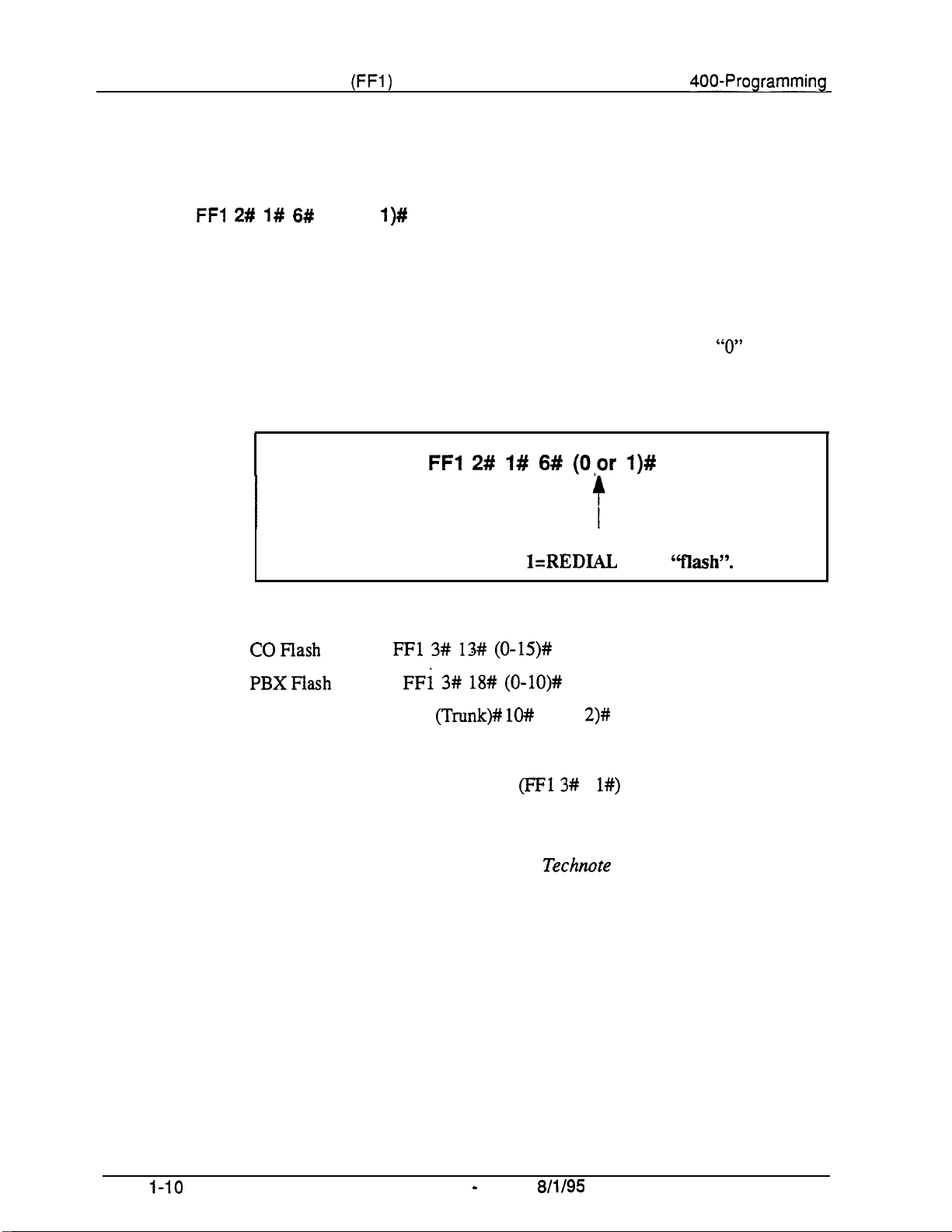
Chapter 1. System Programming
(FFi)
Section
400-Programming
Auto
Software Version: All Versions
Address:
Description
Flash Redial
FFl 2# 1# 6#
This address determines whether the DBS will send a “flash” signal to the CO
on loop-start trunks when the REDIAL key is pressed. By default, the
REDIAL key sends a flash before redialing a number.
If your DBS system is connected to a PBX, set this address to “0” (sending a
flash may place the line to the PBX on hold).
(0 or
l)#
Programming
Related Programming
FFl 2# l# 6# (0,or
O=REDIAL does not send “flash”.
l=REDIAL
l)#
sends
6‘flashy’.
Notes
COFlash
PBXFlash
Trunk Port Type: FF2
Flash Timing.
a flash when REDIAL is pressed.
Ground-Start Trunk Restriction.
functional for ground-start trunks. See
information.
Timer:
Timer:
FFl 3# 13# (0-15)#
FFl 3# 18# (0-lO)#
(Trunk)# lO#
The CO Flash Timer
(1 or
(FF13#
The Flash and Redial features are not
Technote
2)#
1
l#)
determines the duration of
13
(March 1992) for more
Page
Technical Manuals Online! - http://www.tech-man.com
I-10
DBS Manual - Issued
8/l/95
DBS-70-400

Section
400-Programming
One Touch Dial
Software Version: All Versions
Address:
FFl 2# l# 7#
(0 or
l)#
Chapter 1. System Programming
(FFI )
Description
The One-Touch Dial feature enables
single programmable key. This feature is enabled
setting (One-Touch Dial cannot be deactivated).
users
to dial an extension by pressing a
regardicss
of the
program
DBS-70-400
Technical Manuals Online! - http://www.tech-man.com
DBS Manual- Issued
8/l/95
Page l-11
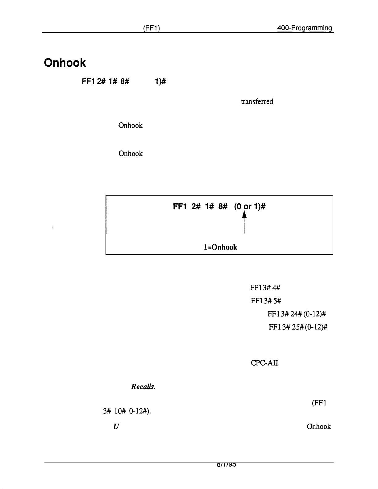
Chapter 1. System Programming
(FFl)
Section
400-Programming
Onhook
Software Version: All Versions
Address:
Description
Transfer
FFl 2# 1# 8#
This address determines whether a call can be
the PROG key.
l
If Onhook Transfer is enabled (default setting), the user can transfer a call
by placing the call on hold, dialing the extension number, and then hanging
UP-
*
If Onhook Transfer is disabled, the user places the call on hold, dials the
extension number, then presses PROG (or “8” if using an SLT or DSLT
phone) and hangs up to transfer the call.
(0 or
l)#
Programming
transferred
O=Onhook Transfer is disabled.
l=Onhook
Transfer is
without pressing
enabled.
Related Programming
Attendant Transfer Recall Timer for CO Calls: FFl 3# 4# (0-12)#
Extension Transfer Recall Timer for CO Calls: FFl 3# 5# (0-12)#
Attendant Transfer Recall Timer for Intercom Calls:
Extension Transfer Recall Timer for Intercom Calls:
Notes
Call Transfer Limitation With CPC-A.
can be onhook-transferred to other extensions. In
trunk and intercom calls can be onhook-transferred.
Transfer
answered, it will automatically transfer to the attendant. Timing for the
attendant transfer is controlled by the Attendant Call Reversion Timer (FFl
3# lO# o-12+9.
VA U Interaction.
Transfer to allow the VAU to transfer calls.
Recalls.
FFl 3# 24# (0-12)#
FFl 3# 25# (0-12)#
In CPC-A versions, only trunk calls
CPC-AI1
If a transferred call recalls to an extension and is not
If a VAU (Voice Announce Unit) is used, enable Onhook
and CPC-B, both
Technical Manuals Online! - http://www.tech-man.com

Section 400-Programming
Key Bank Hold
Software Version: All Versions
Address:
FF1 2# l# 9#
(0 or
l)#
Chapter 1. System Programming
(FFl)
Description
Programming
Use this address to enable or disable the Key Bank Hold feature in the DBS
system.
l
If Key Bank Hold is enabled:
-
a phone user can switch back and forth between trunk calls (by
pressing the FF key for each trunk) without placing the current
trunk on hold.
-
an Attendant phone can press a DSS/BLF key to automatically
transfer a trunk call to an extension without pressing HOLD
first.
In both cases, the DBS will automatically place the current trunk call on
System Hold (anyone can pick up the call) when the phone user presses the
FF key or DSS/BLF key.
l
If Key Bank Hold is disabled (default setting), the phone user must press
HOLD before accessing a second trunk or transferring a call.
L
DBS-70-400
Technical Manuals Online! - http://www.tech-man.com
DBS Manual - Issued
O=Key
l=Key
8/l/95
Bank Hold is disabled.
Bank Hold is enabled.
Page 1-13
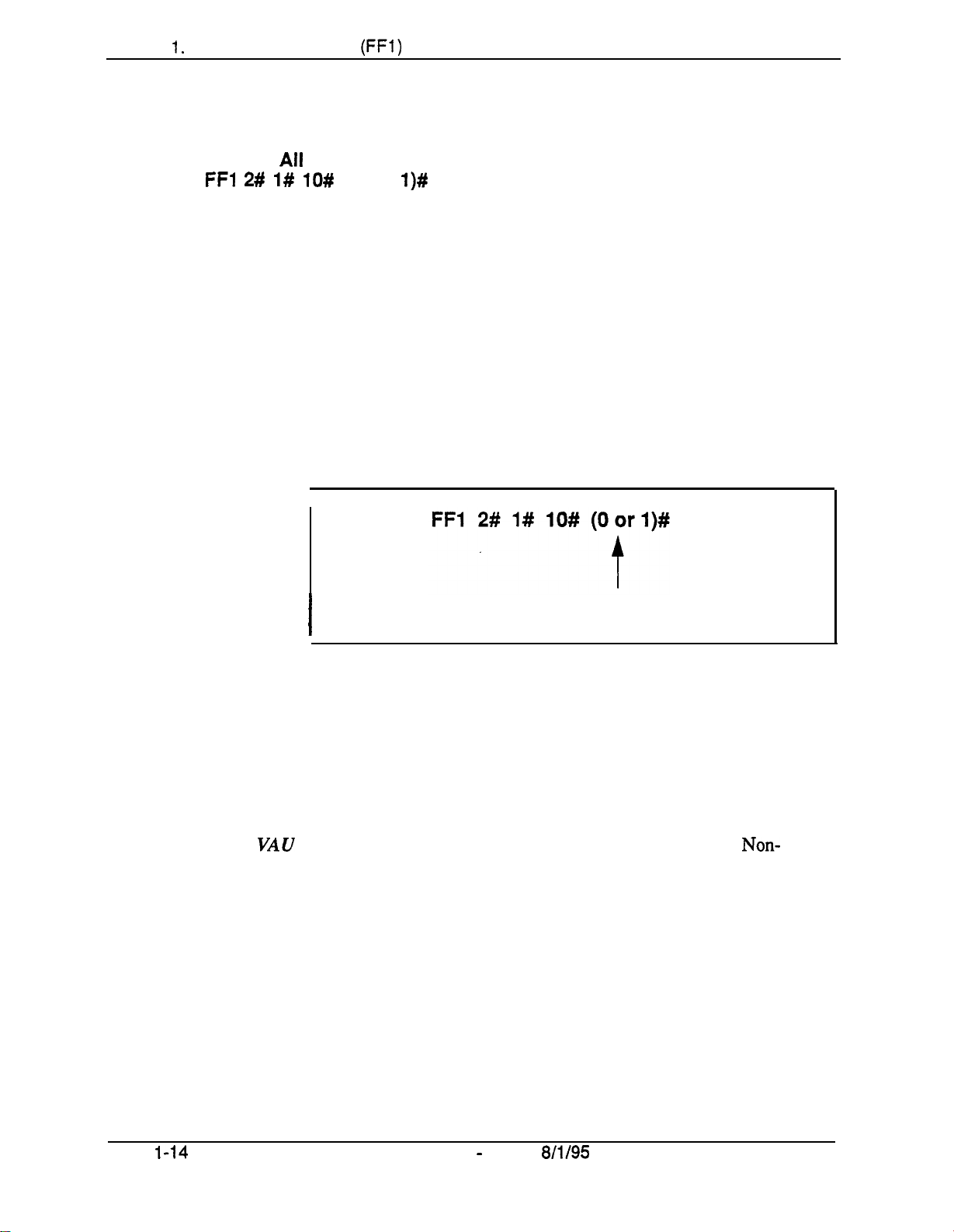
Chapter I. System Programming
(FFl)
Non-Appearing Trunk Hold
Software Version:
Address:
FFl 2# l# lO#
All
Versions
(0 or
l)#
Section 400-Programming
Description
Programming
This address determines who can pick up trunk calls that are on hold. It
applies to DBS phones that don’t have dedicated key appearances for trunk
calls (the phone user can’t tell which trunk is being used for incoming or
outgoing calls).
Choose one of the following:
l
Exclusive Hold:
was placed on hold.
l
System Hold (default setting):
The call can be retrieved only on the extension where it
Any extension can pick up the call.
I
O=Exclusive Hold is used for non-appearing trunk calls.
I
l=System Hold is used for non-appearing trunk calls.
Notes
Page
l-14
Applicable Phone Types.
telephones.
Number
that do not have a key appearance for trunk calls can only hold one trunk at a
time.
VAU Interaction.
Appearing Trunk Hold to “Exclusive Hold” to prevent other extensions from
picking up calls being handled by the VAU.
of
Trunks That Can Be Held Without Key Appearances.
DBS Manual - Issued
This feature applies to both single-line and digital
If a VAU (Voice Announce Unit) is used, set
8/l/95
Non-
DBS-70-400
Phones
Technical Manuals Online! - http://www.tech-man.com

Section 400-Programming
SLT Flash Control
Software Version: All Versions
Address:
FFl 2# 1# 11#
(0 or
l)#
Chapter 1. System Programming
(FFl)
Description
Table l-l. SLT
This address determines how the DBS will respond to a second hookflash
during a call transfer on an SLT (Single-Line Telephone). By default, the
second hookflash will retrieve the held call.
To transfer a call on an SLT, the user
then dials the extension number to transfer the call to. If the extension is busy
or not answered, the SLT user can hookflash again to either
or retrieve the held call. depending on the
this address.
The following table further explains the SLT call transfer process for both
settings:
Hookflash
Control Settings
If SLT Flash Control is Set to “0” . . .
--
;;eh;y;r
hookflashes to place a call
hookflashes
setting.(“O”
to place the call on hold,
returu
to dial tone
or
“l”, respectiveiy)
If SLT Flash Control Is Set to “1” . . .
--
i;eh;y;r
hookflashes to place a call
in
-- The.user dials an extension number to -- The user dials an extension number to
transfer the call. The extension is transfer the call. The extension is
busy or does not answer.
busy.
-- The user hookflashes a second time -- The user hookflashes a second time
to receive dial tone.
-- The user dials another extension*.
to retrieve the held call.
-- The user can then hookflash a third
time to place the call on hold and
-- When the extension rings, the user
receive dial tone.
hangs up to transfer the held call.
-- The user dials another extension.
*
Or, the user can hookflash a third
-- When the extension rings, the user
time to retrieve the held call. hangs up to transfer the held call.
NOTE: This address does not affect how the hookflash functions when the
SLT user is listening to dial tone.
DBS-70-400
Technical Manuals Online! - http://www.tech-man.com
DBS Manual - Issued
8/l/95
Page l-l
5
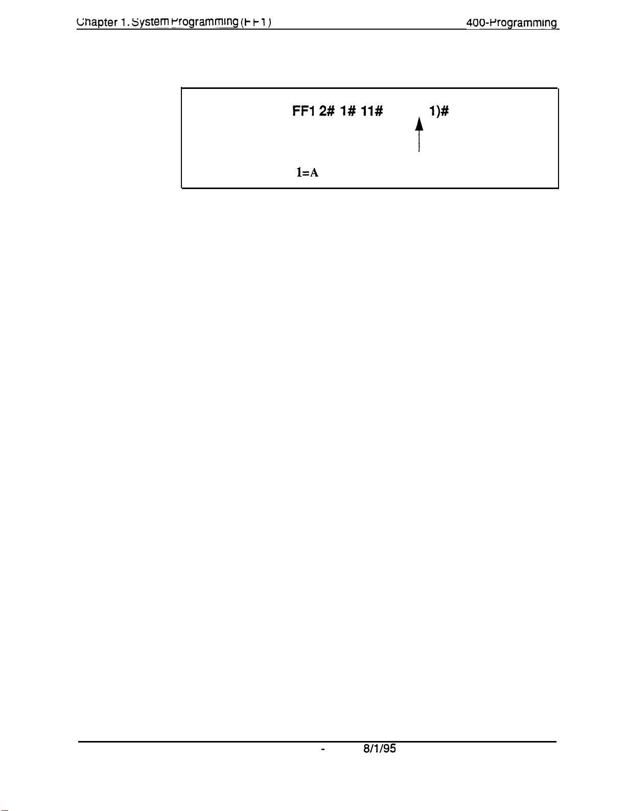
Lnapter 1. system rrogramming (t f- i )
Programming
section
400~Wogrammlng
FFI 2# 1# 11#
O=A
second
l=A
second SLT hookflash retrieves a held call.
(0 or
l)#
t
SLT hookflash results in dial tone.
Page
Technical Manuals Online! - http://www.tech-man.com
1-16
DBS
Manual - Issued
8/l/95
DBS-70-400
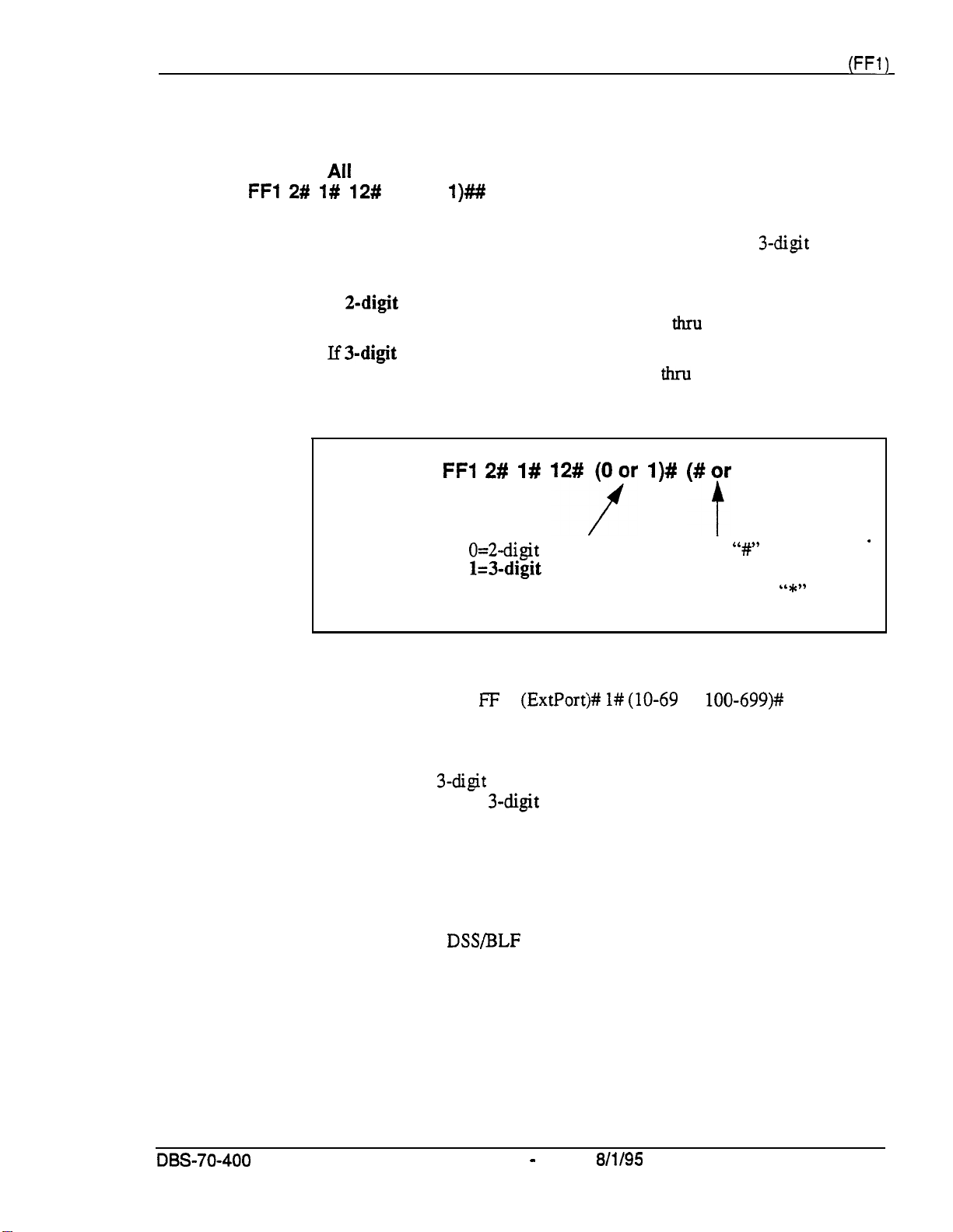
Section 400-Programming Chapter 1. System Programming
(FFl)
Extension Number Digits
Software Version:
Address:
FFl 2# l# 12#
Ail
Versions
(0 or
l)##
Description
This address determines whether the DBS will
numbers.
l
If 2-digit numbers are
available for assignment. Number Range: 10
l
If
3-digit numbers are
numbers are available. Number Range: 100
Programming
Related Programming
used, a maximum of 60 extension numbers are
used (default setting), a maximum of 600 extension
FFl 2# l# 12#qr
0=2-d@
1=3-digit
numbers
numbers
use
2-digit or 3-digit extension
thru
69.
&u-u
699.
l)# (#jr
A second
*)
‘W’
is required to
confirm the new numbering
plan. (Or, enter “*” to cancel
the new numbering plan.)
’
Notes
Extension Numbers: FF 3
Interaction With Larger Systems.
(ExtPortj# l# (lo-69
If more than 60 phones are installed in
or
lOO-699)kt
your system, use 3-digit extension numbers. Sites with fewer than 60 phones
can use either 2-digit or 3-digit extension numbers.
Interaction With Voice Mail.
If your system uses Voice Mail, use 3-digit
numbers in order to match extensions with Voice Mail boxes.
Precaution for Changing Extension Number Digits.
Changing this setting
can adversely affect other DBS settings that are based on extension numbers,
such as entries for
DSWBLF
keys and Call Forwarding.
DES-70-400
Technical Manuals Online! - http://www.tech-man.com
DBS Manual - Issued
8/l/95
.
Page 1-17
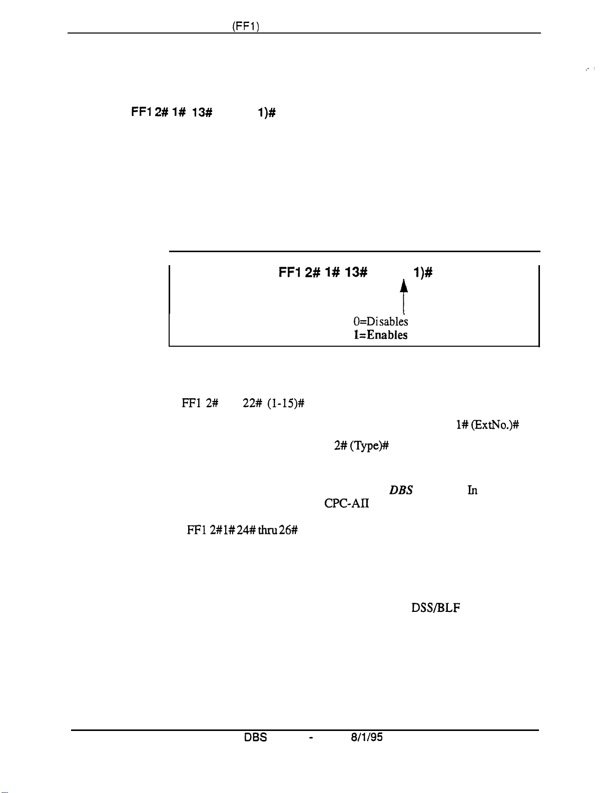
Chapter 1. System Programming
(FFl)
Alternate’ Attendant
Software Version:
Address:
FFl 2#
CPC-A and CPC-B Versions Prior to 2.0
l# 13#
(0 or
Section 400-Programming
l)#
Description
Use this address to enable or disable the use of an Alternate Attendant phone.
By default, the Alternate Attendant is enabled.
When enabled, the Alternate Attendant phone receives overflow intercom
calls from the Primary Attendant. The Alternate Attendant also has full
access to Attendant features.
Programming
I
Related Programming
Attendant Overflow for Primary Attendant (CPC-B Version 1.0 only):
FFl 2#
Extension Numbers (assigning to ports): FF3 (ExtPort)# l#
1#
22# (l-15)#
FFI 2# 1# 13#
O=Disables
l=Enables
(0 or
t
I
l)#
the Alternate Attendant.
the Alternate Attendant.
(ExtNo.)#
.
Notes
Terminal Type: FF3 (ExtPort)# 2#
Alternate Attendant Phone Settings In Later
(Type)#
DBS
Versions.
In
CPC-B
Version 2.0 and above, and in all CPC-AII versions, you can program Second,
Third, and Fourth Attendant phones instead of just one Alternate Attendant.
See
FF12# l# 24# thru 26#
Limitations on Assigning Attendant Phones. The
for more information.
DBS system always
.
recognizes the Primary Attendant location at extension port 1, with extension
number 10 or 100; this cannot be changed. However, you can change the
assignment of the Alternate Attendant -- but it is recommended that you leave
its default extension number at 11 or 101, so that a DSS/BLF console can be
used with it. (The Alternate Attendant is assigned by default to port 2, but it
can be reassigned to another port --
as long as extension 11 or 101 is assigned
to the new port.)
DBS
Page 1-18
Technical Manuals Online! - http://www.tech-man.com
Manual - Issued
8/l/95
,
DBS~70-400
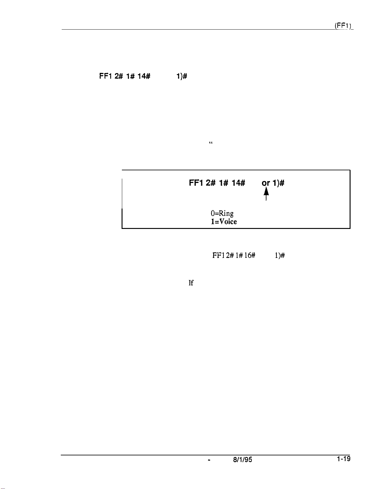
Section 400-Programming
Attendant Intercom Calling
Software Version:
Address:
FFl 2# l# 14#
All
Versions
(0 or
l)#
Chapter 1. System Programming
(FFI)
Description
Use this address to determine how intercom calls from an Attendant phone
are announced at extension phones -- by ringing the extension, or by
immediately establishing a voice path over the extension loudspeaker. By
default, a voice path is established when an Attendant dials an extension.
After the connection is established, the Attendant can change from voice to
ring (or vice versa) by dialing “ 1”.
Programming
I
Related Programming
Alert Tone for Voice Calls:
FFl
2# l#
14#I
(0
O=Ring
l=Voice
FFI 2# l# 16#
tone intercom calling from Attendant.
intercom calling from Attendant.
orl)#
+
I
(0 or
l)#
Notes
DBS-70-400
Interaction With VAU.
VAU is used, the VAU will not answer a call from an Attendant unless the
Attendant dials a “1” after dialing the VAU.
DBS Manual - issued
If this address is set to “Voice intercom calling” and a
Page
8/l/95
1-19
Technical Manuals Online! - http://www.tech-man.com

uapter
1. system rrogrammlng
(t-i- 1)
Extension Intercom Calling
Software Version:
Address:
FFl 2# I# 15#
Ail
Versions
(0 or
l)#
section
400~Wogramming
Description
Use this address to determine how intercom calls from another extension will
be announced at extension phones -- by ringing the extension, or by
imrnediately establishing a voice path over the extension loudspeaker. By
default, a voice path is established when an extension dials another extension
-- the called party can hear and talk to the caller without lifting the handset.
After the connection is established, the caller can switch from voice to ring
(or vice versa) by dialing “1”.
Programming
Related Programming
Alert Tone for Voice Calls:
FFl 2# 1# 15#
O=Tone intercom calling from extension.
l=Voice intercom calling from extension.
FFl 2# 1# 16#
(0 or
4
I
(0 or
I)#
l)#
Notes
Page
l-20
Interaction
With
VAU.
If this address is set to “Voice intercom calling” and a
VAU is used, the VAU will not answer a call from an extension unless the
extension dials a “1” after dialing the VAU.
DES
Manual -
Issued 8/l/95
OBS-70-400
Technical Manuals Online! - http://www.tech-man.com
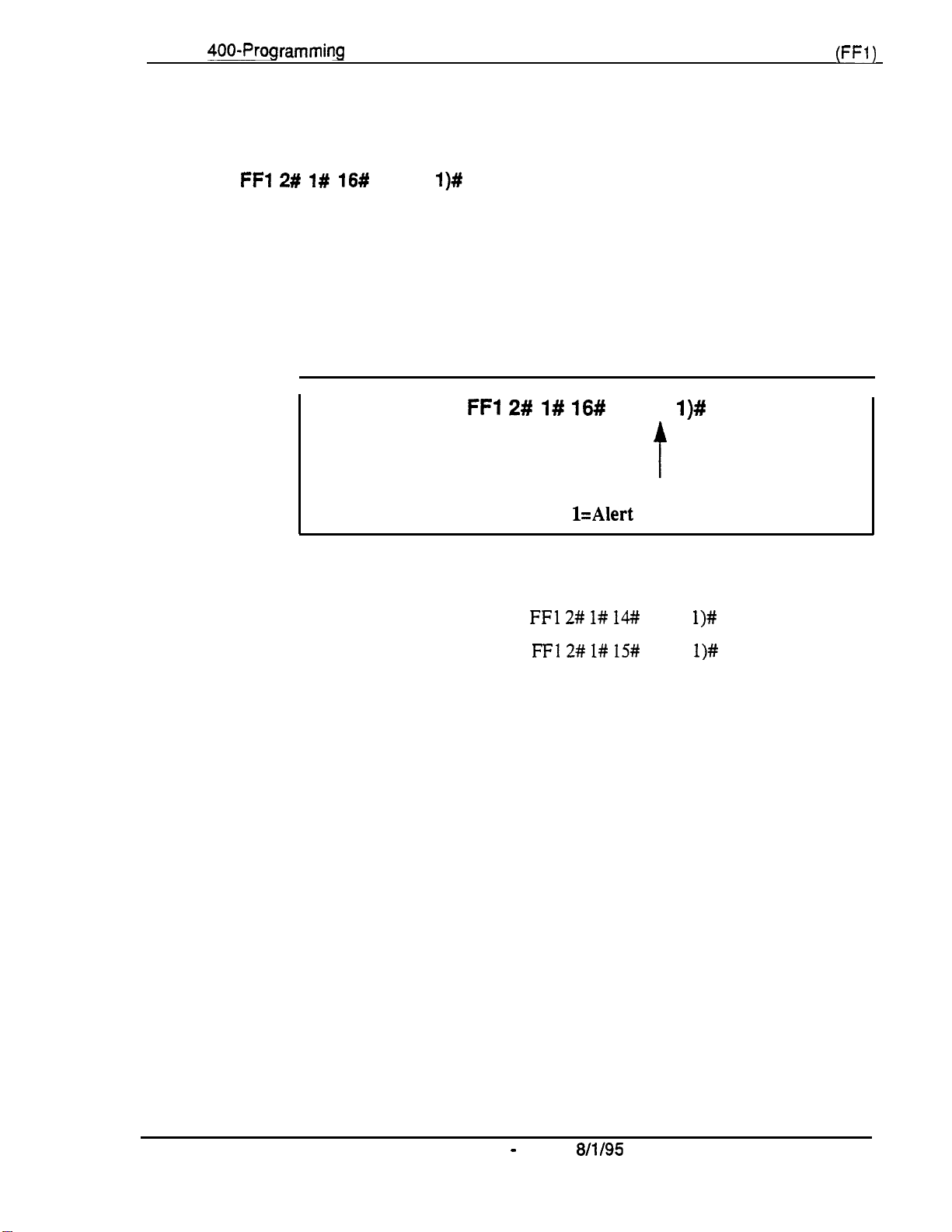
Section
400-Programming
Alert Tone for Voice Calls
Software Version: All Versions
Address:
FFl 2# l# 16#
(0 or
l)#
Chapter 1. System Programming
(FFl)
Description
Use this address to determine whether voice intercom calls are preceded by
an initial alert (“splash”) tone. By default, the alert tone is enabled.
The alert tone (if enabled) will be sounded for
voice path is established.
Programming
I
Related Programming
Attendant Intercom Calling:
Extension Intercom Calling:
FFl 2#
0.5
seconds before the caller’s
l#
16#
(0 or
l)#
f
O=Alert tone is disabled.
l=Alert
FFl 2# l# 143
FFl 2# l# 15#
tone is enabled.
(0 or
(0 or
I
l)#
l)#
DBS-70-400 DBS Manual - Issued
Technical Manuals Online! - http://www.tech-man.com
8/l/95
Page l-21

Chapter 1. System Programming
(FFl)
Alert Tone for Busy Override & OHVA
Software Version: All Versions
Address:
FFI 2# l# 17#
(0 or
l)#
Section 400-Programming
Description
This address determines if Attendant Override, Busy Override, and Offhook
Voice Announce (OHVA) calls are preceded by an alert tone. By default, the
alert tone is disabled.
This feature is governed by state law --
Programming
Related Programming
Busy Override Send: FF3
Busy Override Receive:
Page Group Extensions:
FFl
2# I#
(ExtPort)# 9#
FF3
FF3
some states require the alert tone.
17#
(0
O=Alert
l=Alert tone is enabled.
(0 or
(ExtPort)# lO#
(ExtPort)# 18#
or
l)#
tone is disabled.
l)#
(0 or
thru
l)#
25#
(0 or
l)#
Page 1-22 DBS Manual - Issued
Technical Manuals Online! - http://www.tech-man.com
8/l/95
DBS-70-400

Section
400-Programming
System Installation Area Code
Software Version: All Versions
Address:
FFl 2# 1# 18#
(0 or
l)#
Chapter 1. System Programming
(FFl)
Description
This address determines if the DBS site requires a “1” to be dialed before the
area code to make long-distance calls. This setting will affect the way the
DBS handles Toll Restriction (TRS)
distance calls.
In almost all cases, the default setting (“1” must be dialed) should not be
changed.
Programming
Related Programming
Toll Restrictions: FF7
Least Cost Routing:
and
Least Cost Routing (LCR) for
FFl 2# I# 18#
O=“l” is not required before a long-distance call.
t=“l”
must be dialed before a long-distance call.
FF8
(0 or
t
l)#
long-
Notes
DBS-70-400
Technical Manuals Online! - http://www.tech-man.com
Interaction With TRS and LCR.
before a long-distance call), the system will look at the
number dialed, whether it’s a “1” or not. This would severely limit the
capability of TRS and LCR, which are based on 3-digit area codes.
If “1” is selected (“1”
system will ignore the first dialed digit (could be “0” or “1”) and look at the
next three digits dialed as the area code.
DBS Manual - Issued
is
required before dialing a long-distance call), the
If
“0”
is selected above (,‘l” is
8/l/95
uot
required
fiist
three digits of the
Page 1-23

Chapter
SSD Name Display
DBS
Manual
-
Issued
8/l/95
DBS-70-400
Software Version: AH Versions
Address:
Description
Programming
FFl 2# l# 19#
TJse
this address to determine how many SSD (System Speed Dial) names can
be displayed at a time on large-display phones, whenever an SSD menu is
displayed.
When 5 names are displayed (default setting), the maximum length for each
name is 16 characters. When 10 names are displayed, the maximum length
for each name is 5 characters.
(0 or
l)#
Related Programming
Override TRS with SSD Numbers:
SSD Display Restriction:
SSD Menu display during call states:
System Speed Dial Names:
System Speed
Dial
FFl 2# l# 19#
FFl 2# l# 5#
FF6 2#
Numbers:
FFlO l#
(0
cy l)#
O=Displays
l=Displays 10 SSD names.
FFl 2# l# 3# (SSD)#
FF3
(SSD)#
(SSD)#
5 SSD names.
(0 or
I)#
(ExtPort)# 26# thru 33# 3#
CONF
(Name)++
@ialedNo.)#
Technical Manuals Online! - http://www.tech-man.com

Section 400-Programming
Chapter 1. System Programming
(FFI)
APVAEC
software VetSiOn:
Address:
Slot Assignment
FFl 2# 1# 20#
Description
Programming
CPC-A Version 3.3 or higher; CPC-All; and CPC-B Version 5.0 or higher
(2-9 or
This program is only used with third-party API applications. Its purpose is to
designate which Analog Extension Card (AEC) is used for voice channel
connections to the API product.
2-18)#
1
FFl 2# l# 20#
(2-9
oy
2118)#
t
Analog Extension Slot used for voice
paths to a third-party API product.
NOTE:
must be a digital port).
Valid Ranges --
CPC-A and CPC-AII: 2-9
CPC-B: 2-18
I.
Default:
Do not set this to “1” (slot 1
(no assignment)
**
Related Programming
Voice Mail Busy Tone:
Terminal Type: FF3 (ExtPort)# 2#
Notes
DBS-70-400
Technical Manuals Online! - http://www.tech-man.com
Third-Party Voice Mail Systems Not Integrated With the DBS.
systems, the API card is not required. Set up Call Forward ID codes so that
the DTMF codes will be sent to the appropriate Voice Mail box (ON/OFF
PROG - AUTO - *
Feantre
Operation
DBS Manual - Issued
FFl 2# l# 21#
-
[Ext] - [up to 16 char.] - HOLD). See
for more information.
(0 or
(21-28,31-38
8/l/95
l)#
or
41-48)#
In these
-
Section 700-
Page 1-25
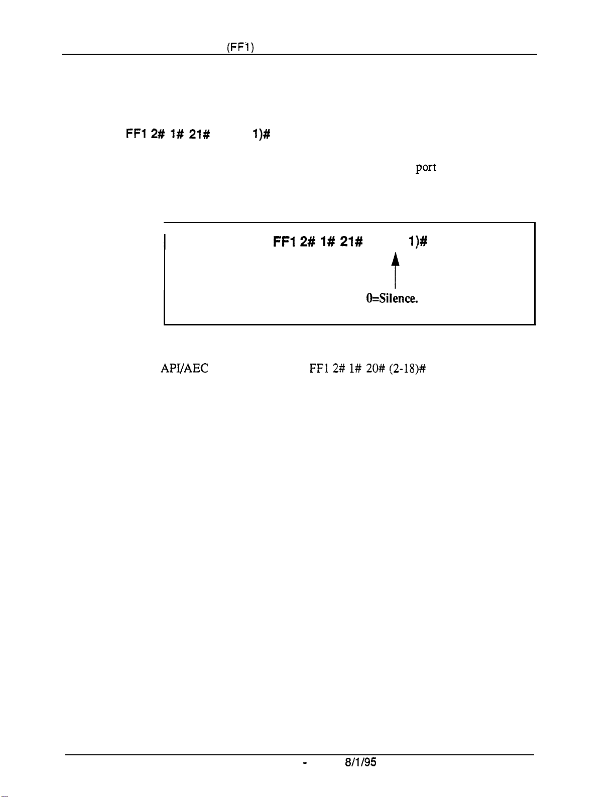
Chapter
1.
System Programming
(FF1)
Voice Mail Busy Tone
Software Version: All-Versions
Address:
FFl 2# 1# 21#
(0 or
l)#
Section
400-Programming
Description
This address determines what is sent to a voice-mail uort at the conclusion of
a call -- either silence or a busy tone. By default, the DBS sends silence.
Programming
I
Related Programming
API/AEC
Slot Assignment:
FFl 2# l# 21#
FF1 2# l# 20# (2-18)#
L
(0 or
l)#
O=Silence.
1 =B usy tone.
Page l-26
Technical Manuals Online! - http://www.tech-man.com
DBS Manual - Issued
8/l/95
DBS-70-400 .
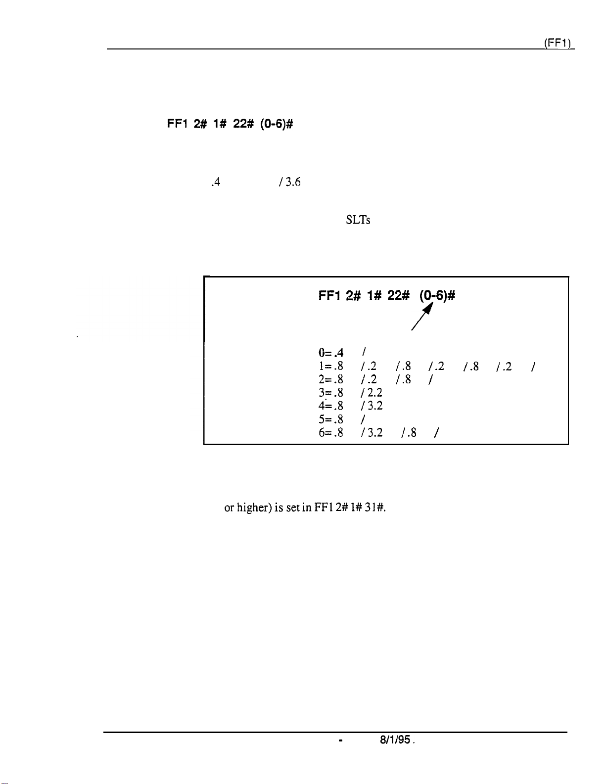
Section 400-Programming
Analog Transfer Ring Pattern
Software Version:
Address:
FFl 2# l# 22# (O-6)#
CPC-A Only (Version 3.21 or higher)
Chapter 1. System Programming
(FFl)
Description
Programming
This address determines which ringing pattern is used for transferred calls to
devices connected to analog extension ports. By default, the ringing pattern
is .4 seconds on
This setting is typically used to assign specific ringing patterns for calls
transferred to a modem, or for
transferred calls.
13.6
seconds off.
SLTs
that require distinctive ringing for
FFl 2# l# 22# (O-6)#
f
Setting (in seconds):
O=.4on/ 3.6 off
l=.8on I .2
2=.8on/ .2 off /.8
3=.8on
4=.8on
5=.8on/ 5.2 off
6=.8on
off /.8
12.2
off
13.2
off
13.2
off/ .8 on/
on /.2
on /2.2 off
off /
7.2
off
.8
on/.2
off/1
off
Notes
DBS-70-400
Technical Manuals Online! - http://www.tech-man.com
Analog Transfer Ring Pattern Setting for CPC-AN and CPC-B.
Analog Transfer Ping Pattern for CPC-AI1 (all versions) and CPC-B (Version
2.11
orhigher)issetinFFl
DBS Manual - Issued
2#
1#31#.
8/l/95.
The
Page l-27
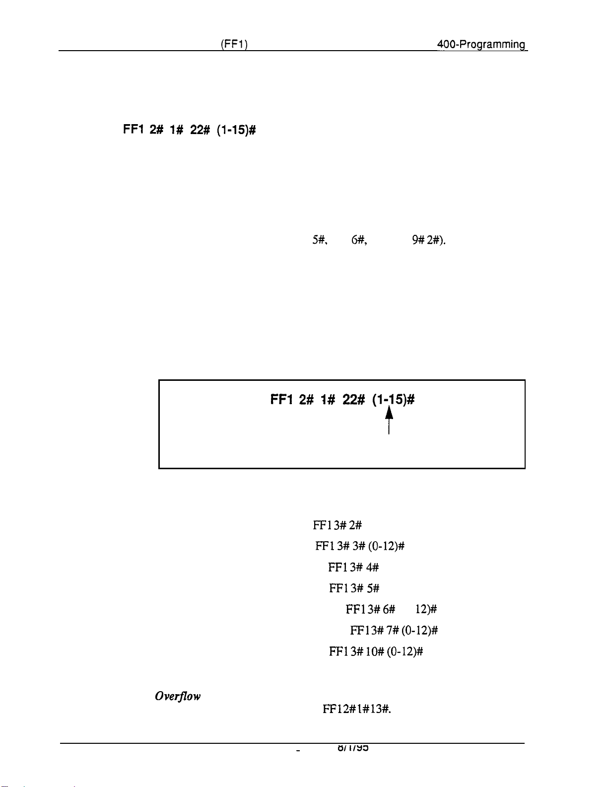
Chapter 1. System Programming
(FFl)
Section
Attendant Overflow for Primary Attendant
Software Version:
Address:
FFl 2# l# 22# (l-15)#
CPC-B Version 1 .O only
400-Programming
Description
Programming
This address determines the maximum number of trunk calls that can be
stacked
at the Primary Attendant phone. By default, up to 8 calls can be
stacked at a time.
Calls exceeding the set limit are automatically transferred to other extensions.
To determine which extensions receive ovefflow trunk calls, use the Day and
Night Delayed Ring tables
(FF4
5#,
FF4
6#,
and FF4 9#
2#).
The following types of calls can be stacked at the Primary Attendant:
l
Incoming trunk calls.
l
Hold recalls.
l
Transferred recalls.
l
Hunt group recalls.
l
Call reversions.
FFl 2# I# 22# (l-15)#
f
Number of Calls That Can Be Stacked
(default: 8)
Related Programming
Attendant Hold Recall Timer:
Extension Hold Recall Timer:
Attendant Transfer Recall Timer: FFl 3# 4# (0-12)#
Extension Transfer Recall Timer: FFl 3# 5# (0-12)#
Attendant Hunt Group Recall Timer:
Extension Hunt Group Recall Timer:
Attendant Call Reversion Timer:
Notes
Overflow Intercom
Calls.
Intercom calls will automatically ovefflow to the
Alternate Attendant, if enabled in FFl 2# I#
Technical Manuals Online! - http://www.tech-man.com
FFl 3# 2#
(0-12)#
FFl 3# 3# (0-12)#
FFl 3# 6#
(0-
FFl 3# 7# (0-12)#
FFl 3# lO# (0-12)#
13#.
12)#
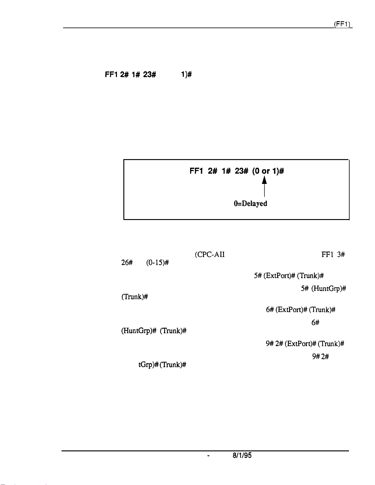
Section 400-Programming Chapter 1. System Programming
(FFl)
Delayed Ring
Software Version:
Address:
FFl 2# l# 23#
CPC-All (all versions) and CPC-B Version 2.0 or higher
(0 or
l)#
Description
This address determines if delayed ringing is allowed for CO trunks. By
default, delayed ringing is disabled.
Delayed ringing is an automatic transfer of unanswered calls -- if an incoming
call is not answered at one extension, the system will send the call to another
extension (the first extension will cease ringing).
Programming
Related Programming
CO Delayed Ring Timer
26#
(O-15)#
(CPC-AI1
O=Delayed
l=Delayed ringing is enabled.
and CPC-B Ver 3.1 or higher):
ringing is disabled.
FFl 3#
CO Delayed Day Ring Assignments: FF4 5#
CO Delayed Day Ring Assignments for Hunt Groups:
(Trunk)#
CO Delayed Night 1 Ring Assignments : FF4 6#
CO Delayed Night 1 Ring Assignments for Hunt Groups:
(HuntGrp)# (Trunk)#
CO Delayed Night 2 Ring Assignments: FF4 9# 2#
CO Delayed Night 2 Ring Assignments for Hunt Groups: FF4 9#
(Hun
tGrp)# (Trunk)#
(ExtPort)# (Trunk)#
FF4 5#
(ExtPort)# (Trunk)#
(ExtPort)# (Trunk)#
(HuntGrp)#
FF4
6#
2#
DBS-70-400 DBS Manual - Issued
Technical Manuals Online! - http://www.tech-man.com
8/l/95
Page 1-29
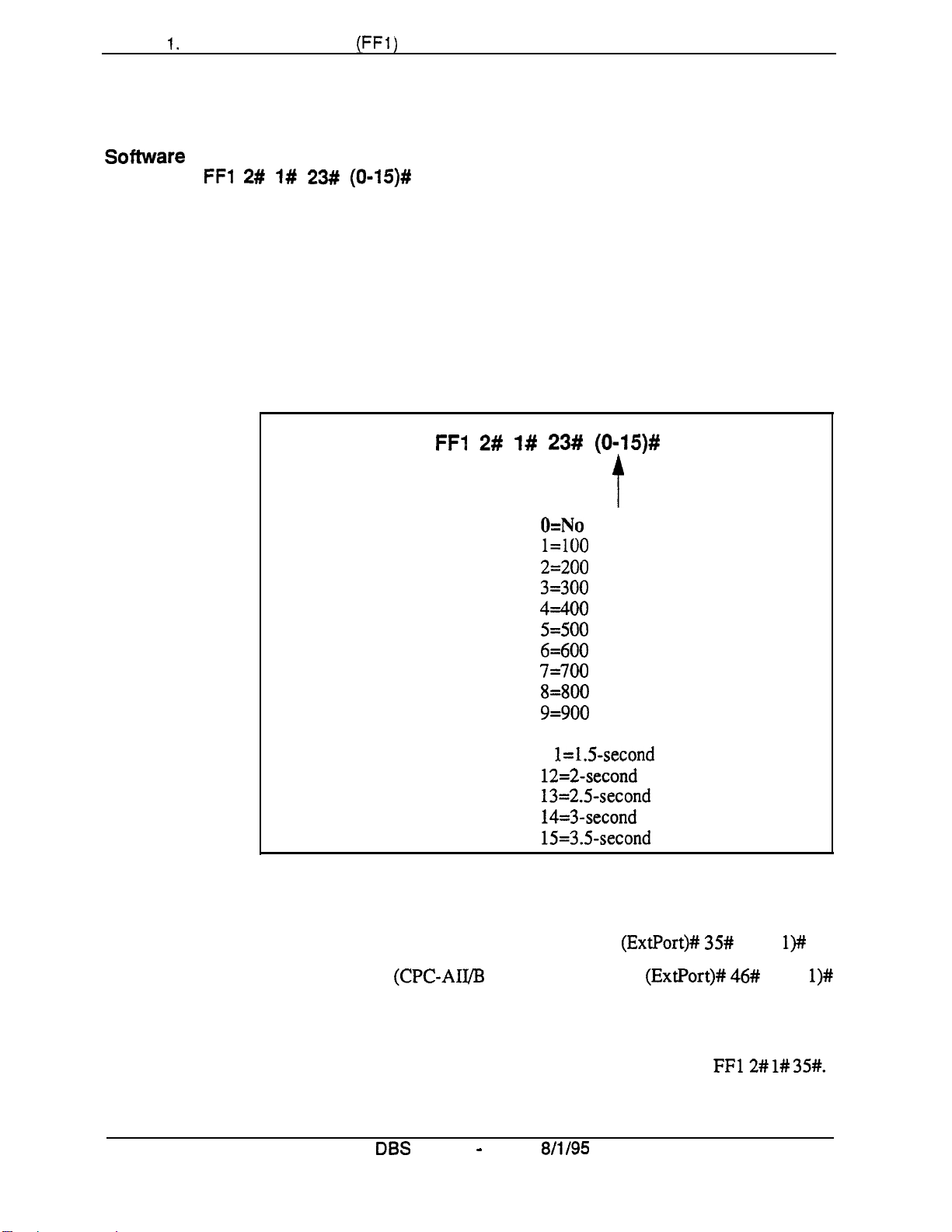
Chapter I. System Programming
(FFI)
AEC Disconnect Signal Duration
Software Version: CPC-A Version 3.3 or higher
Address:
FFl 2# l# 23# (0115)#
Section 400-Programming
Description
Programming
Use this address to set the AEC card (VB-43621A) to provide a positive
disconnect signal, and determine the duration of the signal. By default, the
disconnect signal is not sent.
If set, analog extension ports will provide a disconnect signal (open loop)
upon hangup. Sending this signal allows quick disconnect from third-party
voice mail systems.
FFI 2#
l#
23# (0-15)#
O=No
disconnect signal.
l=lOO
ms signal will be sent.
2=200
3=300
4=400
5=500
6=600
7=700
8=800
t
ms signal will be sent.
ms signal will be sent.
ms signal will be sent.
ms signal will be sent.
ms signal will be sent.
ms signal will be sent.
ms signal will be sent.
9=900 ms signal will be sent.
lO=l-second signal will be sent.
1
l=lS-second
12=2-second
13=2.5-second
14=3-second
15=3.5-second
signal will be sent.
signal will be sent.
signal will be sent.
signal will be sent.
signal will be sent.
Related Programming
AEC Disconnect (CPC-A 3.3 or higher): FF3
AEC Disconnect (CPC-AIIB 5.0 or higher): FF3
Notes
Page l-30
Technical Manuals Online! - http://www.tech-man.com
AEC Disconnect Signal Duration for CPC-B Versions.
5.0 and higher, the AEC Disconnect Signal Duration is set in
DBS
Manual - Issued
8/l/95
(ExtPort)# 35#
(ExtPort)# 46#
For CPC-B Version
FF12# l# 35#.
(0 or l)#
(0 or
DBS-70-400
l)#
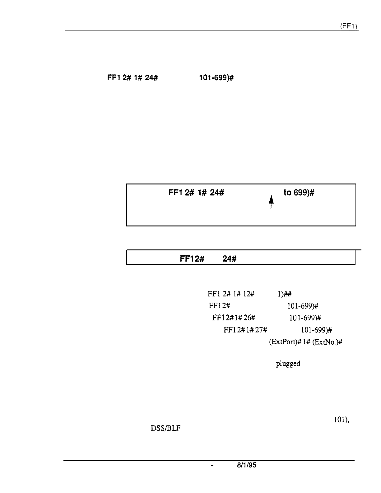
Section 400-Programming
Second Attendant Position
Software Version:
Address:
FFI 2# I#
CPC-All (all versions) and CPC-B Version 2.0 or higher
24#
(11-69 or
10%699)#
Chapter 1. System Programming
(FFl)
Description
Programming
This address assigns an extension number as the
By default, the Second Attendant position is extension 101.
When all line appearances at the Primary Attendant are busy, calls will
transfer in sequence to the Second. Third, and Fourth Attendants. If all line
appearances are busy on all Attendants, calls will transfer to the Attendant
Transfer Extension (if assigned).
To assign a Second Attendant position . . .
FFl
2# 1#
24#
(11-69
or
101
Second
to699)#
Attendant position.
+
Extension Number
(default:
To clear the Second Attendant position . . .
FFl 2#
1#
24#
11
or 101)
CONF ON/OFF
Related Programming
Extension Number Digits:
Third Attendant Position:
Fourth Attendant Position:
Attendant Transfer Extension:
Extension Numbers (assigning to ports): FF3
Notes
Programming Restrictions.
Attendant port before its extension number can be programmed or cleared.
Also, use another phone to program or clear its extension number (e.g., you
can’t use ext. 101’s phone to program ext. 101 as the Second Attendant
position).
Limitations on Assigning Attendant Phones.
leave the Second Attendant at the default assignment (extension 11 or
so that a DSS/BLF console can be used. System default for the Primary
Attendant phone is extension 10 or 100, assigned to port 1 -- and Primary
Attendant assignments cannot be changed.
FFl 2# I# 12#
FFl 2#
1# 2% (11-69 or
FFl 2# l# 26#
FFl 2# l# 27#
A telephone must be plugged into the Second
(0 or
(1 l-69 or IO
l).##
lOl-699)#
1-699)#
(1 l-69 or
(ExtPortj# l# (ExtNo.)#
It is recommended that you
lOl-699)#
lOl>,
DBS-70-400
Technical Manuals Online! - http://www.tech-man.com
DBS Manual - Issued
8/l/95
Page 1-31
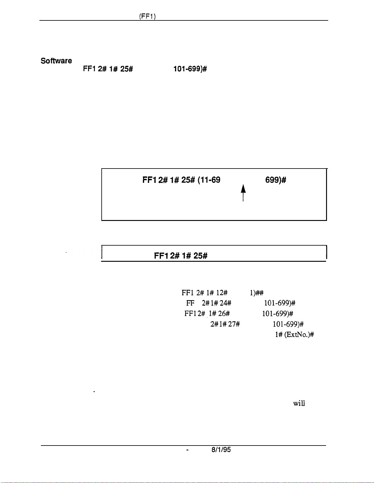
Chapter 1. System Programming
(FFl)
Third Attendant Position
Sofhuare
Address:
Version: CPC-Ail (all versions) and CPC-8 Version 2.0 or higher
FFl 2#
l# 25#
(11-69 or
Section 400-Programming
101-699)#
Description
Programming
This address assigns an extension number as the Third Attendant position.
By default, no extension is assigned as the Third Attendant.
When all line appearances at the Primary Attendant are busy, calls will
transfer in sequence to the Second, Third, and Fourth attendants. If all line
appearances are busy on all Attendants, calls will transfer to the Attendant
Transfer Extension (if assigned).
To assign a Third Attendant position . . .
FFl 2# 1# 25# (11-69
or 101 to
699)#
t
Extension Number
(default:
To clear the Third Attendant position . . .
FFl 2# l# 25#
no Third Attendant assigned)
CONF ON/OFF
Related Programming
Extension Number Digits:
Second Attendant Position: FF 1 2# l#
Fourth Attendant Position: FFl
Attendant Transfer Extension: FFI 2# l#
Extension Numbers (assigning to ports): FF3 (ExtPort)# l#
Notes
Page 1-32
Programming Restrictions.
Attendant port before its extension number can be programmed or cleared.
Also, use another phone to program or clear its extension number (e.g., you
can’t use ext. 102’s phone to program ext. 102 as the Third Attendant
I
position).
Limitation on Assigning the Third Attendant. The
allow you to assign extension 10 or 100 as the Third Attendant position. This
is the system default for the Primary Attendant phone, which cannot be
changed.
FFl 2# l# 12#
2#, l# 26#
A telephone must be plugged into the Third
DBS Manual - Issued
(0 or
24#
(1 l-69 or lOl-699)#
(11-69 or lOl-699)#
27#
8/l/95
l)##
(11-69 or
DBS system
lOl-699)#
(ExtNo.)#
wili
DBS-70-400
not
Technical Manuals Online! - http://www.tech-man.com
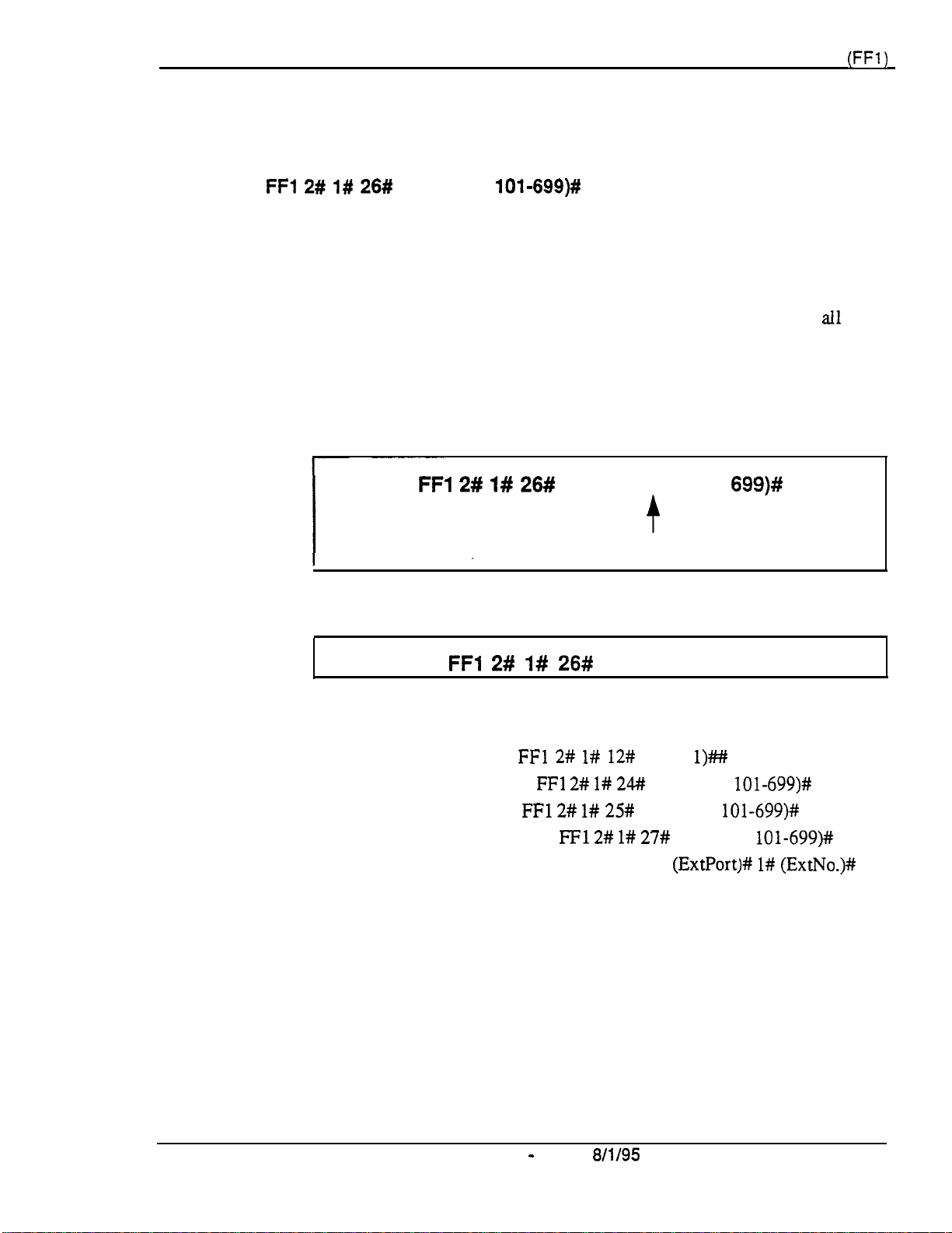
Section 400-Programming
Fourth Attendant Position
Software Version:
Address:
FFl 2# 1# 26#
CPC-All (all versions) and CPC-B Version 2.0 or higher
(11-69 or
10%699)#
Chapter 1. System Programming
(FFl)
Description
Programming
This address assigns an extension number as the Fourth Attendant position.
By default, no extension is assigned as the Fourth Attendant.
When all line appearances at the Primary Attendant are busy, calls will
transfer in sequence to the Second, Third, and Fourth Attendants. If
appearances are busy on all Attendants, calls will transfer to the Attendant
Transfer Extension (if assigned).
To assign a Fourth Attendant position . . .
FFl 2# I# 26#
To clear the Fourth Attendant position . . .
FFl 2# l# 26#
(11-69 or 101 to
Extension Number
(default:
CONF ON/OFF
f
no Fourth Attendant assigned)
699)#
all
line
Related Programming
Extension Number Digits:
Second Attendant Position:
Third Attendant Position:
Attendant Transfer Extension:
Extension Numbers (assigning to ports): FF3
Notes
DBS-70-400
Programming Restrictions.
Attendant port before its extension number can be programmed or cleared.
Also, use another phone to program or clear its extension number (e.g., you
can’t use ext. 103’s phone to program ext. 103 as the Fourth Attendant
position).
Limitation on Assigning the Fourth Attendant.
allow you to assign extension 10 or 100 as the Fourth Attendant position.
This is the system default for the Primary Attendant phone, which cannot be
changed.
FFl 2# l# 12#
FFl 2# 1# 24##
FFl 2# l# 25#
FFl 2# l# 27#
A telephone must be plugged into the Fourth
DBS Manual - Issued
8/l/95
(0 or
(1 l-69 or
(11-69 or
l)#
lOl-699)#
101-699)#
(11-69 or
(ExtPort)# l# (ExtNo.)#
The DBS system will not
lOl-699)#
Page l-33
Technical Manuals Online! - http://www.tech-man.com
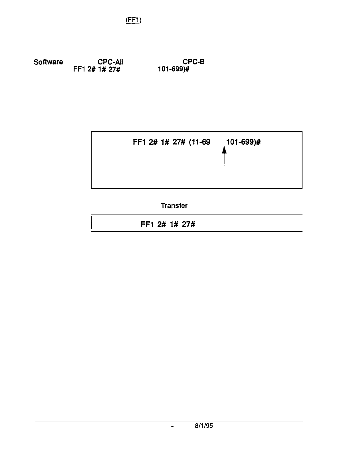
Chapter 1. System Programming
(FFI)
Attendant Transfer Extension
Sofhnrare
Address:
Version:
FFl 2# 1# 27#
CPC-All
(11-69 or
(all versions) and
lOl-699)#
CPC-B
Section 400-Programming
Version 2.09
or
higher
Description
Programming
If all line appearances are busy on all Attendants (Primary, Second, Third and
Fourth), calls will transfer to the extension assigned in this address.
To assign an Attendant Transfer Extension . . .
FFl 2# l# 27# (11-69
To clear the Attendant
I
FFl 2# I# 27#
Tra.nsfer
(default:
Extension . . .
or
10%699)#
t
Extension Number
no Transfer Extension assigned)
CONF ON/OFF
I
Notes
Pilot Number Restriction.
extension --
it cannot be a hunt group pilot number.
The overflow position must be an installed
Page 1-34
Technical Manuals Online! - http://www.tech-man.com
DBS Manual - Issued
8/l/95
DBS-70-400

Section 400-Programming
Attendant Override
Software Version:
Address:
FFl 2# l# 28#
CPC-Ail
(0 or
Chapter 1. System Programming
(all versions) and CPC-B Version 2.09 or higher
l)#
(FFi j
Description
Use this address to enable or disable the Attendant Override feature. which
allows an Attendant phone to “barge into” a trunk or intercom call in progress
on any extension -- even if the extension has been programmed to block
barge-ins. By default, Attendant Override is enabled.
When a barge-in occurs, all three parties can hear and talk to each other.
Programming
Related Programming
klert Tone for Busy Override & OHVA:
FFl
2# l#
28#
(0
O=Disables
l=Enables
FFl 2# l# 178
or
l)#
Attendant Override.
Attendant Override.
(0 or
l)#
DBS-70-400
Technical Manuals Online! - http://www.tech-man.com
DBS Manual - Issued
8/l/95
.
Page l-35

Chapter 1. System Programming
(FFI)
Section
400-Programming
Attendant LED Alarm Indication
Software Version: CPC-B Versions 2.09 to 4.0 (requires Attendant Feature Package)
Address:
FFl 2# l# 29#
(0 or
l)#
Description
Use this address to allow or disallow the Alarm feature (LED lights to
indicate an alarm condition) to be assigned to an FF key on an Attendant
phone. By default, the Alarm feature can be assigned.
NOTE: The Attendant Feature Package (AFP) was discontinued in CPC-B
Version 5.0.
Programming
I
Related Programming
AFP Key Assignn tents:
FFI 2# 1# 29#
O=Alarm
I=Alarm feature
feature cannot be assigned to Attendant FF key.
FF5
( 1 W
152)#
(0 or
I)#
f
can be assigned to Attendant FF
(
1-72)#
(FF 12
4)#
key.
Notes
Page l-36
InstaUing AFZ?
EPROM Chip 1 on the CPC-B card with an AFP chip. Make sure the new
chip is installed in the proper direction. See
complete
infomlation.
Installation of the AFP software requires the replacement of
DBS Manual -
Issued
Technote
8/l/95
4 (September 1991) for
DBS-70-400
Technical Manuals Online! - http://www.tech-man.com

Section
400-Programming
Chapter 1. System Programming
(FFl)
Extension
(BLF) Delayed Ring
Software Version:
Address:
Description
FFI 2# l# 30#
Use this address to enable or disable Delayed Ringing for intercom calls. By
default, Extension
Delayed Ringing is a call-forwarding feature for unanswered calls -- if an
incoming call is not answered at one extension, the system will send the call
to another extension.
NOTE:
key.
Programming
CPC-All (all versions) and CPC-6 Version 2.0 or higher
(0 or
The extension to which the call is forwarded must have a DSS/BLF
l)#
(BLF)
Delayed Ringing is disabled.
FFl
2# 1# 30# (0
O=Extension
l=Extension Delayed Ringing is enabled.
Delayed Ringing is disabled.
or
t
l)#
Related Programming
Extension Delayed Ring Table:
Extension Delayed Ring Timer (CPC-B 2.0 or higher):
Call Forward-No Answer Timer (CPC-B prior to 2.0):
FF4 8#
(ExtPort)# (ExtPort)#
FFl 3# 27# (0-15)#
FFl 3# 19#
(0 or
(0-lS)#
l)#
DBS-70-400
Technical Manuals Online! - http://www.tech-man.com
DBS Manual - Issued
8/l/95
Page l-37

Chapter 1. System Programming
(FFl)
Analog Transfer Ring Pattern
Software Version:
Address:
FFl 2# 1# 31# (016)#
CPC-All (all versions) and
CPC-B
Section
400-Programming
Version 2.11 or higher
Description
Programming
Table
1-2.
Analog Transfer Ring Patterns (vary depending on analog connection)
Address
I
Setting
0
1
Use this address to choose a distinctive ringing pattern for calls transferred to
analog SLT phones. This setting is typically used for calls transferred to a
modem, or for SLT phones requiring distinctive ringing for transferred calls,
There are 7 different patterns (numbered
O-6)
to choose from. The pattern for
each setting depends on the analog connection --
*
an SLT phone connected directly to an AEC card;
l
an SLT phone connected to an OPX Adapter; or
l
an SLT phone connected to an SLT-A
FFl 2# I# 31#
(6port
(0-6)#
Adapter).
Transfer Ring Pattern setting
(see table below)
Ring Pattern (no. of seconds on/off) for SLT phones connected to . . .
I I
AEC Card
son/40ff
lon/.25off/lon/.25off/
OPX Adapter
5on135off
3onlloff
SLT Adapter (SLT-A)
25onI .25
.25onI
offI25onI
3.5
off
3.5
off
2
3
4
5
6
lon/.25off(lon/3off
1
lonl3off
1
onl6off
1
onl4offll
onl2off
onl7off
I I
I
2onl2off
1 on/2
I 1
on/
1
onl5off
1
onl7off
Related Programming
Analog Transfer Ring Pattern (CPC-A 3.21 or higher):
Terminal Type: FF3
Extension Ring Pattern:
Page l-38
Technical Manuals Online! - http://www.tech-man.com
DBS
(ExtPort)# 2# (Type)#
FF3 (ExtPort)#
Manual
-
Issued
off
3.5 off
811195
1
on
I
on/3
I
lonl7off
.50nl7
.25 on I
39# (O-9)#
.
13.5
off
off
off
.25
off/.25
FFI 2# 1#
on I7off
22#
(0-6)#
DBS-70-400

Section 400-Programming Chapter 1. System Programming
(FFl)
Multiple
DID/DNIS
Software Version:
Address:
FFl 2# l# 32#
Description
CPC-B Version 4.0
(0 or
l)#
or higher
Use this address to enable or disable Multiple DID for analog trunks, or
Multiple DID and DNIS for Tl trunks. By default. Multiple DID/DNIS is
disabled.
With Multiple DID/DNIS enabled, one DID or DNIS number can be assigned
to multiple extensions, which will simultaneously ring when an outside caller
dials the DID or DNIS number.
l
DID
stands for “Direct Inward Dialing.” DID can be used only in systems
using analog trunks exclusively (no other types of trunks are used in the
system). Up to 500 DID numbers can be assigned to extension numbers in
FFl 8# 3#
l
DNIS
available only with the Tl Interface. You can use DID and
(0000-9999)#
(ExtNo.)#.
stands for “Dialed Number Identification Service.” DNIS is
DNIS
simultaneously in a Tl system. Up to 500 DNIS numbers can be assigned
to extension numbers in
FFl 8# 4# 7# (0000-9999)#
(lo-69 or
lOO-699)#,
in addition to the 500 DID numbers allowed.
Programming
Related Programming
Inbound DID Dial Numbers:
DID/DNIS
DNIS Number Setting:
DID Flexible Ringing Assignments:
(000000- 11111
DNIS Flexible Ringing Assignments:
(000000-llllll)#
FFl 2# l# 32#
O=Disabies
l=Enables
FFl 8# 3# (0000-9999)# (loo-699)##
(enabling trunks for):
FFl 8# 4# 7# (0000-9999)# (lo-69
l>#
(0
or
l)#
$
Multiple DID/DNIS ringing.
Multiple
FFl 8# 4# 6# (Trunk)# 2#
FFl 8# 5# (DIDNo.)# (ExtNo.)#
FFl 8# 6# (DNISNo.)#
DID/DNIS
ringing.
(0-2)#
or
100-699)#
(ExtNo.)#
Extension Numbers (assigning to ports): FF3 (ExtPort)# l#
DES-70-400
Technical Manuals Online! - http://www.tech-man.com
DBS Manual - Issued
8/l/95
(ExtNo.)#
Page 1-39

Chapter 1. System Programming
(FFl)
Section 400-Programming
Notes
Restrictiun
Version 3.1; however, it only controls Multiple DID (DMS cannot be used
with this version).
DID
Hardware and Power Requirements.
each card provides 8 ports. The card requires dial-pulse dialing and an
external,
instructions.
DZDIDNZS
DMS numbers.
Central
DBS, it
the wink is received, the CO should wait at least 200 ms before sending the
digits.
Trunk Requirement.
(see FP 1 8# 4# 6#
Simultaneous Ringing.
assigned the same
call. If you later disable Multiple
lowest-numbered’port
Far CPC-B Version 3.1.
-48V
power supply. See Section
Digit Length Requirement.
Oj’j?ce
Requirement.
fist
receives a wink from the DBS before sending the digits. Once
Individual trunks must be enabled for DID or DMS
Trunk# 2#).
DID/DNTS
wi!l
When the CO sends a
If Multiple
number will ring for the incoming
ring for the
This address is also present in CPC-B
The DID trunk card is required:
300-Installation
The DBS only supports 4-digit DID/
DID/DNIS
DID/DNIS,
DID/DMS
is enabled, all extensions
only the extension at the
call.
for cabling
DID/DMS
call to the
DlD/DMS
Call Forwarding Interaction..
DID/DXIS
extensions. the simultaneous ringing will also apply to the call-forward
destination extensions. In other words, all call-forward paths will be
followed simultaneously for the same
up. If you later disable Multiple
assigned to the extension at the lowest-numbered port will be followed.
extensions are programmed to call-forward to different
If
Multiple
DID/DNIS
DlD/DNIS,
DID/DMS
only the call-forwarding path
is enabled, and the
call, until someone picks it
Page l-40
DBS Manual - issued
Technical Manuals Online! - http://www.tech-man.com
8/l/95
DBS-70-400

Section
400~Programming
Page Duration
Software
Address:
Version:
FFI 2# l# 33#
CPC-All (all versions) and CPC-B Version 3.1 or higher
(0 or
l)#
Chapter 1. System Programming
(FFI)
Description
Programming
This address determines whether the DBS system will automatically close the
paging circuit 60 seconds after a page is initiated. By default, the paging
circuit is left open indefinitely, until the paging person closes the circuit by
hanging up.
O=The
l=The
page circuit remains open indefinitely.
paging circuit remains open for 60 seconds before
the system closes it.
DBS-70-400
Technical Manuals Online! - http://www.tech-man.com
DBS Manual - Issued
8/l/95
Page 1-41
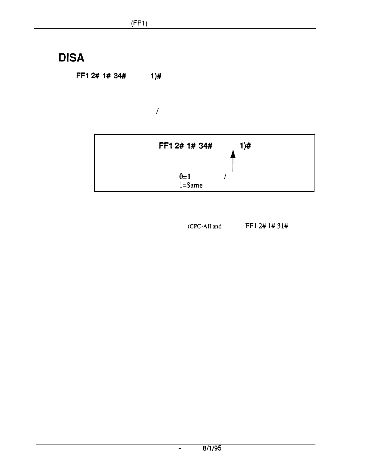
Chapter 1. System Programming
(ITI)
Section 400-Programming
SLT
Software Version:
Address:
Description
DISA
Ring Pattern
FFl 2# l# 34#
CPC-All (all versions) and CPC-B Version 3.1 or higher
Use this address to specify a distinctive ring pattern for DISA calls on SLT
phones, or follow the Analog Transfer Ring Pattern setting. By default, the
pattern is 1 second on / 3 seconds off.
Programming
Related Programming
Analog Transfer Ring Pattern
(0 or
l)#
FFl 2# 1# 34#
kl
i=Same as the Analog Transfer Ring Pattern.
(CPC-AI1 and
(0 or
l)#
1
second on / 3 seconds off.
CPC-B):
FFl 2# l# 31#
(0-6)#
Page 1-42
Technical Manuals Online! - http://www.tech-man.com
DBS Manual - issued
8/l/95
DBS-70-400
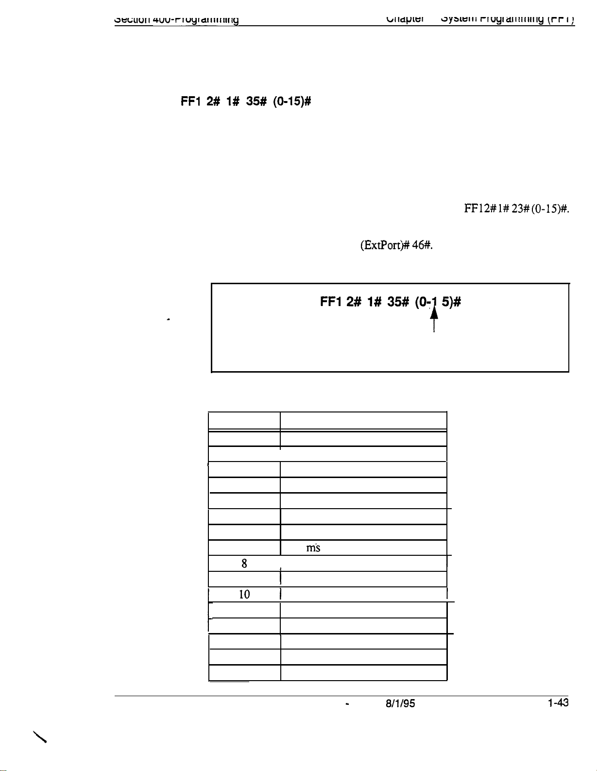
3wau11 4uu-rluylatitiwlg
b11dp3
AEC Disconnect Signal Duration
Software Version:
Address:
FFl 2# 1# 35# (0-15)#
CPC-All (all versions) and CPC-B Version 5.0 or higher
I .
3yaica11 riuyiaii!~iiiiiy
[t-r I;
Description
Programming
Table 1-3.
AEC Disconnect Signal Duration values
Use this address to set the duration of a positive disconnect signal sent from
analog extension ports (VB-43621A version of the AEC card). Sending this
signal allows quick disconnect from third-party voice mail systems. By
default, no disconnect signal is sent.
This address applies to CPC-AI1 and CPC-B. The AEC Disconnect Signal
Duration address for CPC-A (Version 3.3 or higher) is
FFl 2# l#
23#
(0-15)#.
The sending of the AEC disconnect signal can be enabled or disabled on
individual extensions using FF3 (ExtPort)#
46#.
I
FFl 2# l# 35# (O-1 5)#
t
AEC Disconnect Signal Duration setting
Default:
(see table below)
0 (no signal sent)
DBS-70-400
I
Setting
0
1
2
3
4
5
6
7
9
11
12
13
14
15
Value
No disconnect signal sent
I 100 ms
200
ms
300
ms
400
ms
500 ms
600
ms
700
ms
I 800 ms
I
1
900 ms
1
1 second
1.5 seconds
2
seconds
2.5
seconds
3
seconds
3.5
seconds
DBS Manual - Issued
8/l/95
Page
l-43
Technical Manuals Online! - http://www.tech-man.com
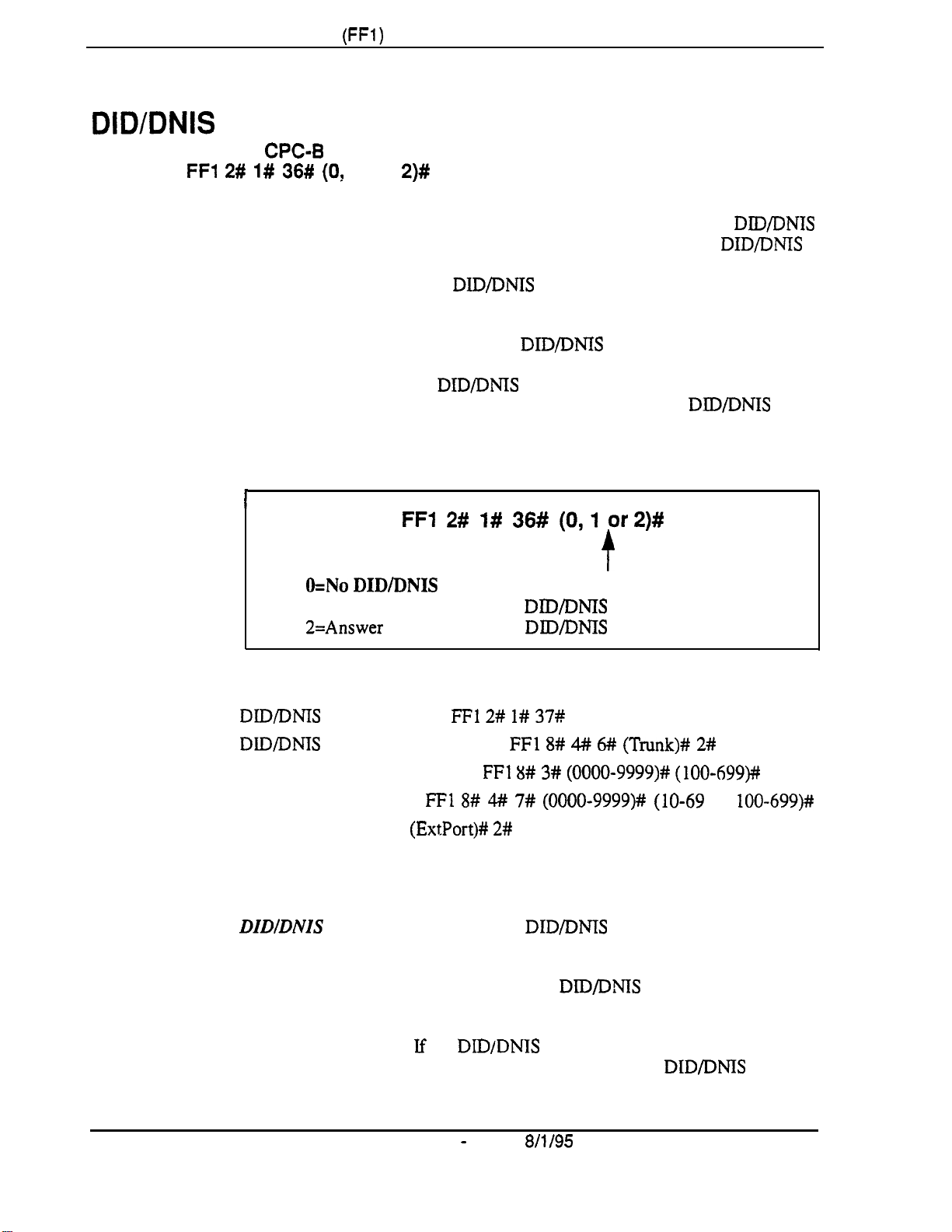
Chapter
1.
System Programming
(FFl)
Section 400-Programming
DIDlDNlS
Software Version:
Address:
Description
to a Voice Mailbox
FFl 2# l# 36# (O!
This address determines whether (and how many) final digits of a
phone number are transmitted to Voice Mail, in cases where the DID/DMS
trunk is assigned to ring directly to Voice Mail (not to a DBS extension
phone). This address allows
system that is not connected to a physical extension.
To implement this feature, assign the DID/DNIS trunks to ring at the Voice
Mail system (using FF4 ring assignment addresses). Once Voice Mail
answers, the DBS sends a DID/DMS Answer Code that signals the Voice
Mail system to open the appropriate mailbox, plus the final DID/DNIS digits
(if any) specified in this address.
Programming
I
CPC-8 Version 6.0 or higher
1 or
O=No
DID/DNIS digits are transmitted (only the Answer Code).
l=Answer Code, then final 4
2=Answer Code, then final 3 DBYDMS digits are transmitted.
2)#
DWDNIS
FFl 2# 1# 36# (0,l or2)#
calls to be routed to a Voice Mailbox
t
DID/DMS
digits are transmitted.
DlD/DNTS
Related Programming
DBXDMS
DlD/DMS
Inbound DID Dial Numbers:
DMS Number Setting:
Terminal Type: FF3
Ringing Assignments (trunks to extensions): FF4 addresses
Notes
DIDIDNIS Digit Transmission.
that are assigned as Voice Mail.
Voice Mail Ports and Hunt Groups.
specific Voice Mail port or a Voice Mail hunt group.
Second Hunt Group.
programmed to transfer calls to a second hunt group, the
not be transferred to the second hunt group.
Answer Code:
(enabling trunks for):
FFl 2# l# 37#
FFl 8# 3# (0000-9999)# (loo-699)#
FFl 8# 4# 7# (0000-9999)# (lo-69
(ExtPort)# 2#
The
If
the DID/DNIS call rings into a hunt group that is
(NNNNNN)#
FFl 8# 4## 6# (Trunk)# 2#
or
(Type)#
DID/DNTS
The
DIDPMS
digits are sent only to ports
digits can be sent to a
DtD/DMS
.
(0-2)#
lOO-699)#
call will
Page 1-44 DBS Manual - Issued
Technical Manuals Online! - http://www.tech-man.com
8/l/95
DBS-70-400
Third-Party
Voice Mail.
This feature can be used with Panasonic’s Voice
Mail system or with third-party Voice Mail systems. If the feature is used
with third-party Voice Mail systems, the Voice Mail can be connected through
analog extension ports or OPX ports.
Call Forward ID Code
DNIS
call is assigned to ring an extension, and the extension is programmed
for
DIDfDNIS
Calls
To An Extension.If
a
DIDI
to forward to Voice Mail, only the Call Forward ID Code will be transmitted
to Voice Mail (the DID/DNIS digits will not).
DZDfDNZS
Data Transmission.
The DID/DNIS digits are transmitted over
the API link using the existing API key code packet.
DBS-70-400
Technical Manuals Online! - http://www.tech-man.com
DBS Manual - issued
8/l/95
Page
l-45
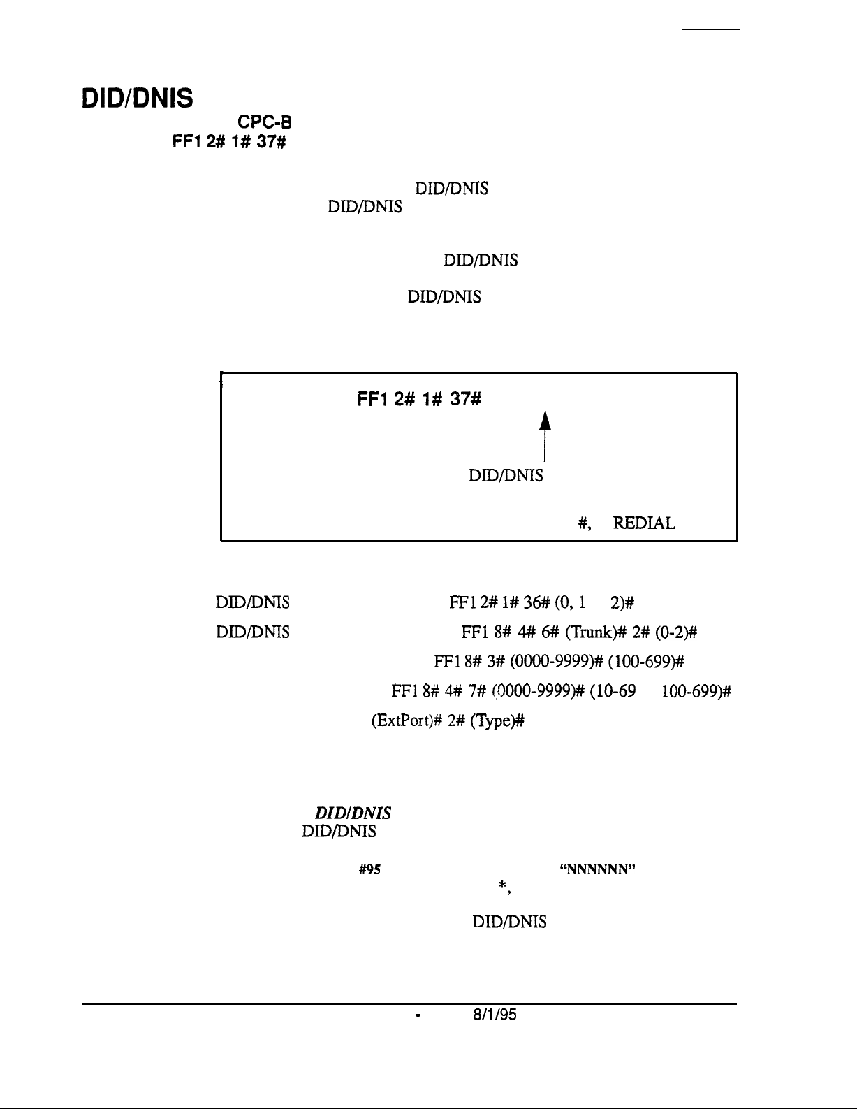
DID/DNIS
Answer Code
Software Version:
Address:
FFl 2# l# 37#
CPC-6
(Code)#
Version 6.0 or higher
Description
Use this address to specify a DID/DNIS Answer Code. The Answer Code is
used for routing DID/DNIS calls to a Voice Mailbox system that is not
connected to a physical extension.
To implement this feature, assign DID/DNIS trunks to ring directly to the
Voice Mail system using FF4 ring assignment addresses. Once Voice Mail
answers, the DBS sends the DID/DNIS Answer Code, which signals the
Voice Mail system to open the appropriate mailbox.
Programming
I
Related Programming
FF1 2# 1# 37#
DID/DNIS
Valid Entries: O-9, *, #, or REDIAL (pause)
(NNNNNN)#
t
Answer Code
(up to 6 characters)
Notes
DID/DMS
DID/DNIS
Inbound DID Dial Numbers:
DNIS Number Setting:
Terminal Type: FF3
Ringing Assignments (trunks to extensions): FF4 addresses
Assigning the
Mode.
phone, or from a key phone where the programming access code has been
entered. Press
Code of up to 6 characters, including O-9, *, #, or REDLAL (for “pause”).
DIDIDNIS Digit Transmission.
that are assigned as Voice Mail.
to a Voice Mailbox:
(enabling trunks for):
FFl 8# 4# 7# (OOOO-9999)## (lo-69
(ExtPort)# 2# (Type)#
DIDIDNIS
The DlD/DNIS Answer Code may be entered from an Attendant
PROG
Answer Code When Not In Programming
##!I5
NNNNNN HOLD
FFl 2# l# 36# (0,l
FFl 8# 4# 6## (Trunk)# 2# (0-2)##
FFl 8# 3# (0000-9999)# (loo-699)##
-- where
The DID/DNIS digits are sent only to ports
or
2)#
“NNNNNN”
or
lOO-699)##
is the Answer
Page 1-46
Technical Manuals Online! - http://www.tech-man.com
DBS Manual - Issued
8/i/95
DBS-70-400
Voice Mail Ports and Hunt Groups.
The DIDIDNIS digits can be sent to a
specific Voice Mail porr or a Voice Mail hunt group.
Second Hunt Group.
programmed to transfer calls to a second hunt group, the
not be transferred to
Third-Party Voice Mail.
If the DID/DNIS call rings into a hum group that is
the
second hunt group.
DID/DNTS
call will
This feature can be used with Panasonic’s Voice
Mail system or with third-party Voice Mail systems. If the feature is used
with third-party Voice Mail systems, the Voice Mail can be connected through
analog extension ports or OPX ports.
Call Forward ID Code for DZDIDNZS Calls To An Extension.Lf
a DID/
DNIS call is assigned to ring an extension, and the extension is programmed
to forward to Voice Mail, only the Call Forward ID Code will be transmitted
to Voice Mail (the DID/DNIS digits will not).
DZDIDNIS
Data Transmission.
The
DIDPNIS
digits are transmitted over
the API link using the existing API key code packet.
DBS-70-400
Technical Manuals Online! - http://www.tech-man.com
DBS Manual - Issued
8/l/95
Page l-47
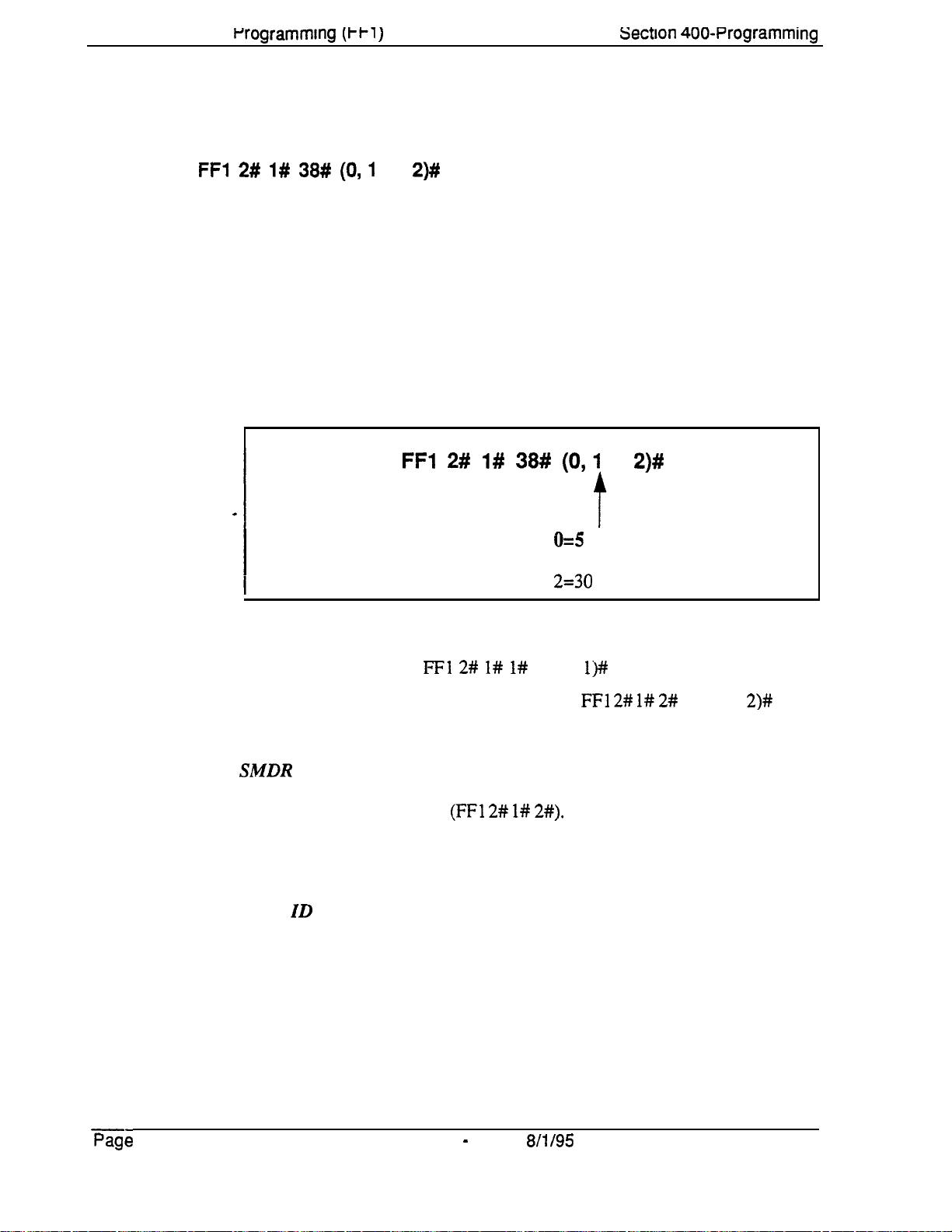
Chapter 1. System
PrOgrammIng
(Wl )
LCD Timer for Caller ID
Software Version:
Address: FFl 2# l# 38# (0,l
CPC-All and CPC-B, Version 6.1 or higher
or
Sectlon 400~Programming
2)#
Description
The LCD Timer determines how long the DBS waits before displaying call
duration timing on the phone’s LCD. This Timer allows Caller ID
information (if available) to appear before the call duration timing is
displayed.
For example, if the LCD Timer is set to 5 seconds (default), call duration
timing will start displaying on the phone’s LCD 5 seconds after an outgoing
number is dialed, or 5 seconds after an incoming call is answered.
Programming
Related Programming
Call Duration Display:
FFl 2# l# 38#
FFl 2# l# l#
(0 or
(0,l
or
2)#
0=5
seconds
1= 16 seconds
2=30 seconds
l)##
SMDR Display Start Timer for CO Calls:
Notes
Page 1-48 DBS Manual - issued
SMDR
The system begins the actual SMDR recording of the call according to the
SMDR Start Timer address (FFl 2# l#
displayed, the LCD Timer has to
means the LCD Timer setting must be equal to or greater than the SMDR
Start Timer.
Caller ID Interaction. The
time that Caller ID information is displayed before the LCD changes to call
duration timing. However, the Timer also controls when call duration display
begins for all types of trunk calls, not just Caller ID calls.
Interaction.
The LCD Timer only affects the
expire
LCD ‘Timer setting will be the actual length of
FFl 2# l# 2#
2#).
In order for call duration to be
after the SMDR Start Timer -- which
8/l/95
(0, 1 or
display
2)#
of call duration.
DBS-70-400
Technical Manuals Online! - http://www.tech-man.com
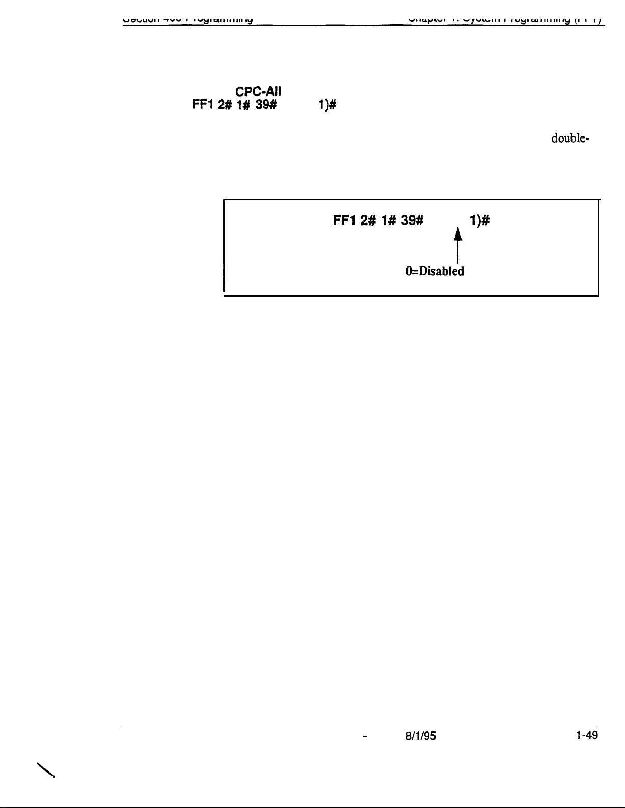
Internal Hold Tone
Software Version:
Address:
FF1 2# l# 39#
CPC-All
and CPC-B, Version 7.0 or higher
(0 or
l)#
Description
Programming
Notes
Use this address to enable or disable Internal Hold Tone, which is a double-
beep heard every 7 seconds by a caller on hold.
FFl 2# l# 39#
MOH
(Music-On-Hold) sound source installed.
Override.
Internal Hold Tone (if enabled) will override any MOH
(0 or
&Disabled
l=Enabled (Internal Hold Tone heard)
I)#
(no Internal Hold Tone)
DBS-70-400
\
Technical Manuals Online! - http://www.tech-man.com
DBS Manual - Issued
8/l/95
Page
l-49
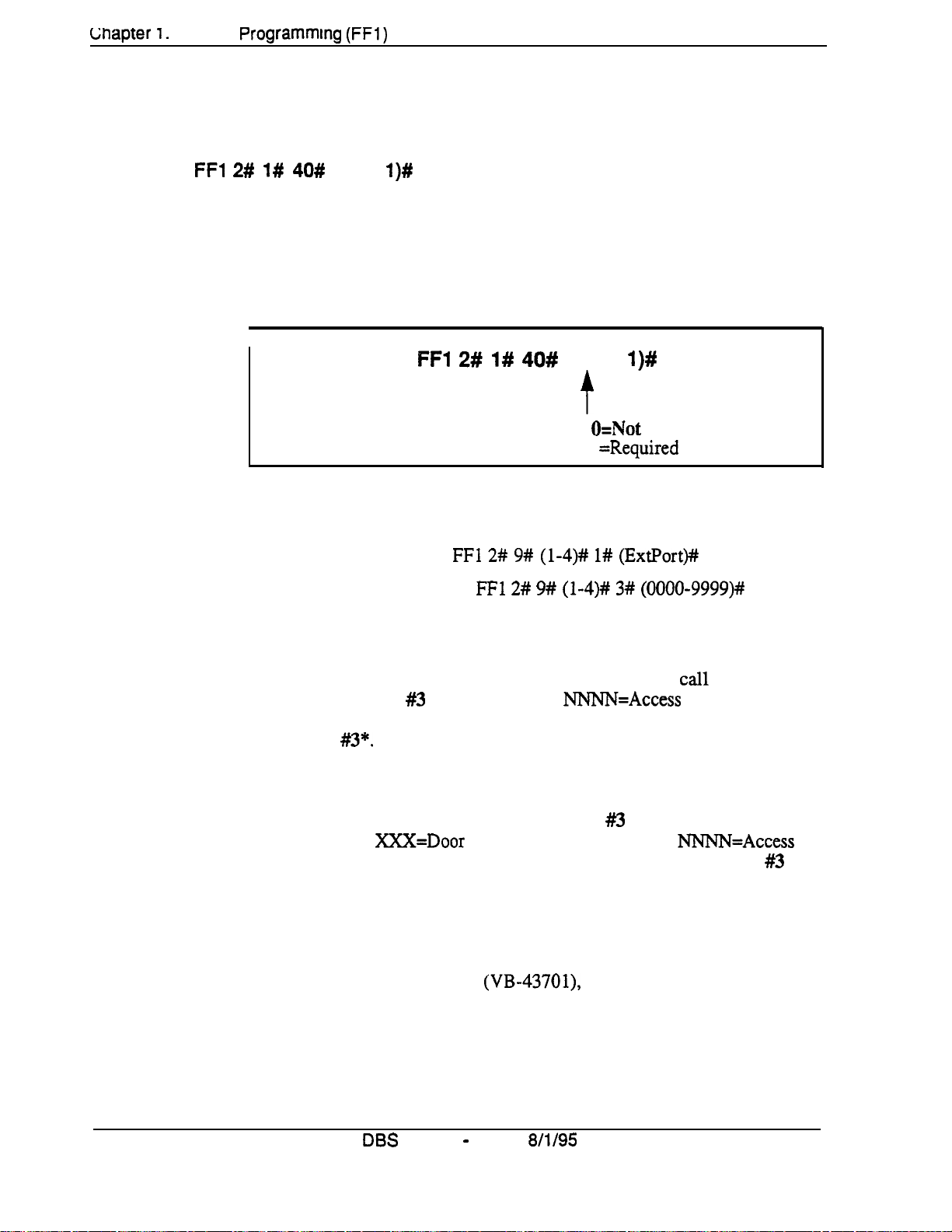
Lnapter 1.
System
Programmtng (FFl)
Door Opener Access Code Required
Software Version:
Address:
FFl 2# l# 40#
CPC-All and CPC-8, Version 7.0 or higher
(0 or
l)#
Section 400-Programming
Description
This address
entered on an extension to unlock the Door Box. This applies to Door Boxes
connected to digital extension ports (not trunk ports).
Programming
I
Related Programming
Door Phone Extensions:
Door Opener Access Code:
Notes
Unlocking the Door Box During a Door Phone
“1” (Required), an extension user answering a door phone call would unlock
the door by pressing #3 NNNN * (where
“0” (Not required), the extension user answering the door phone call would
simply press
determines
FFl 2# l# 40#
#3*.
whether a Door Opener Access Code must be
(0 or
t
FFl 2# 9# (l-4)# l# (ExtPort)##
FFl 2# 9# (l-4)# 3# (0000-9999)#
NNNN=Access
l)#
O=Not
1 =Required
required
Call. If this address is set to
Code). If set to
Unlocking the Door Box From Another Extension. The
unlocked from any other extension not engaged in a door phone call.
address is set to “1” (Required), dial ON/OFF #3 XXX NNNN * on any
extension (where XXX=Door Box extension number, and NNNN=Access
Code) to unlock the door. If set to “0” (Not required), dial ON/OFF #3
XXX * to unlock the door.
Hardware Requirement.
phone devices connected to the VB-437 11 Door Phone Adaptor, which
connects the Door Box to a digital extension port Door Boxes connected to
trunk ports use another Adaptor (VB-43701), and do not utilize the Access
Code.
Page l-50
Technical Manuals Online! - http://www.tech-man.com
DBS
The Door Opener Access Code applies to door
Manual - Issued
8/l/95
door can also be
If this
DBS-70-400
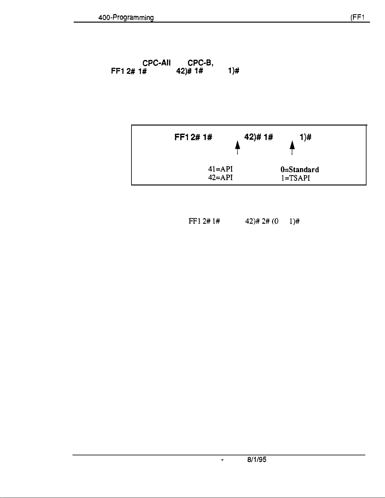
Section
400-Programming
API Port Type
Software Version:
Address:
FFl
2# 1#
CPC-All
(41 or
Chapter 1. System Programming
and CPC-8, Version 7.0 or higher
42)# l#
(0 or
l)#
(FFl
j
Description
Use this address to configure the appropriate API port for TSAPI protocol.
Only one API port should be configured for TSAPI.
Programming
Related Programming
API Baud Rate:
FFI 2# 1#
API Port Number:
41=API Port 1
42=API
FFl 2# I#
(41 or
+
Port 2
(41 or
42)#
1#
42)# 2# (0
(0 or
Port Type:
O=Standard
or
l)#
-r
l=TSAPI protocol
l)#
API
protocol
DBS-70-400
Technical Manuals Online! - http://www.tech-man.com
DBS Manual - Issued
8/l/95
Page l-51

Chapter
1. system rrogrammlng (t t 1)
API Baud Rate
Software Version:
Address:
FFl 2#
CPC-Ail
1# (41 or
section
and CPC-B, Version 7.0 or higher
42)# 2#
(0 or
l)#
400~Programming
Description
The baud rate for the TSAPI port can be set to either 9600 or 19200 bps.
Programming
Related Programming
API Port Type:
Notes
Using
Both
must be set to 9600 bps.
FFl 2# 1#
FFl 2# l#
API Ports.
(41 or
API
Port Number:
41=API Port 1
42=API
(41 or
42)# 2#
Port 2
42)# 1#
(0 qr
Baud Rate:
0=9600
1=19200
(0 or
l)#
bps
bps
l)#
If both API ports are being used, both baud rates
,
Page l-52
Technical Manuals Online! - http://www.tech-man.com
DBS Manual - Issued
8/l/95
DBS-70-400
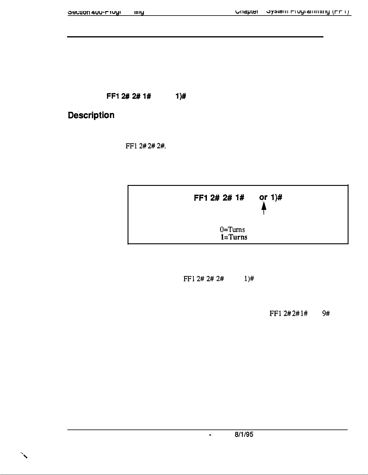
3eGu011 4uu-I-
I uyl
al I I I I
Ill ly
w~apiai
I.
~y3~c111 rluyiaiiiiiwly it-r 11
Serial Port Parameters (TTY Settings)
Parity Check
Software Version: All Versions
Address:
FFl 2# 2# l#
(0 or
l)#
Dbscription
This address determines whether the DBS checks parity over serial port CN6.
By default, parity checking is turned on.
If parity checking is activated, select the parity count -- “Even” or “Odd” -- in
FF12# 2# 2#.
Serial Port CN6 is normally used for SMDR.
Programming
.
Related Programming
Odd/Even Parity:
FFl 2#
FFl 2# 2# 2#
2# 1#
O=Turns
l=Turns
(0 or
(0 qr
l)#
off the parity check.
on the parity check.
l)#
Notes
Checking Communications Parameters.
value, be sure to check all Serial Port addresses -make sure they are set properly.
DBS-70-400
Technical Manuals Online! - http://www.tech-man.com
DBS Manual - Issued
If you later change this address
FF12# 2# l#
8/l/95
thru 9# -- to
Page l-53

Gnapter 1.
system rrogrammtng
p-1 )
Odd/Even Parity
Software Version: All Versions
Address: FFl 2# 2# 2#
(0 or
sectron 400~Programming
l)#
Description
If parity checking for Serial Port CN6 was activated in
address (Odd/Even Parity) determines whether the check is based on an even
count or an odd count. By default, the parity count is even.
Programming
Notes
Checking Communications Parameters.
value, be sure to check all Serial Port addresses -make sure they are set properly.
FF12# 2# l#,
this
FFl 2# 2# 2#
(0 or
O=Odd parity.
l=E
If you later change this address
l)#
t
ven parity.
FF12#
2# l#
thru 9#
-- to
Page 1-54 DBS Manual - Issued
Technical Manuals Online! - http://www.tech-man.com
8/l/95
DBS-70-400

Baud Rate
Software Version:
Address:
FFl 2# 2# 3# (114)#
All
Versions
Description
Programming
Notes
Use this address to set data transmission speed (baud rate) between Serial
Port CN6 and the peripheral equipment attached to it. By default, baud rate is
set at 9600 bits per second.
I
I
Checking Communications Parameters.
value, be sure to check all Serial Port addresses --
make sure they are set properly.
FFl 2# 2# 3# (3;4)#
1=300
bps
2=1200
3-4800
4=9600
If you later change this address
bps
FFl 2# 2# I#
bps
bps
thru 9# -- to
DBS-70-400
Technical Manuals Online! - http://www.tech-man.com
DBS Manual - Issued
8/l/95
Page 1-55

Stop Bit Length
Software Version: All Versions
Address:
FFl 2# 2# 4# (103)#
Description
Programming
Notes
This address sets the length of the stop-bit parameter for transmitted data over
Serial Port CN6. By default, the stop bit length is set to 1 bit.
FFl 2# 2# 4# (I- 3)#
r
l=l bit
2-1.5
bits
3=2
bits
Checking Communications Parameters.
value, be sure to check all Serial Port addresses --
make sure they are set properly.
If you later change this address
FFl
2# 2# l#
thru
9# -- to
Page 1-56 DBS Manual - issued
Technical Manuals Online! - http://www.tech-man.com
8/l/95
DBS-70-400

Data Length
Software Version: All Versions
Address:
FFl 2# 2# 5#
(3 or
4)#
biiapiei
I.
r>ysittiii
rruyrammlrig (rf
I
j
Description
Programming
Notes
This address sets the length of the transmitted data string over Serial Port
CN6. By default, data length is set to 8 bits.
FFl 2# 2# 5#
(3 or
4)#
t
3=7
bits
44
bits
Checking Communications Parameters.
value, be sure to check all Serial Port addresses -make sure they are set properly.
If you later change this address
FFl 2# 2# 1#
thru 9# -- to
DBS-70-400
Technical Manuals Online! - http://www.tech-man.com
DBS Manual - Issued
8/l/95
Page
1-57
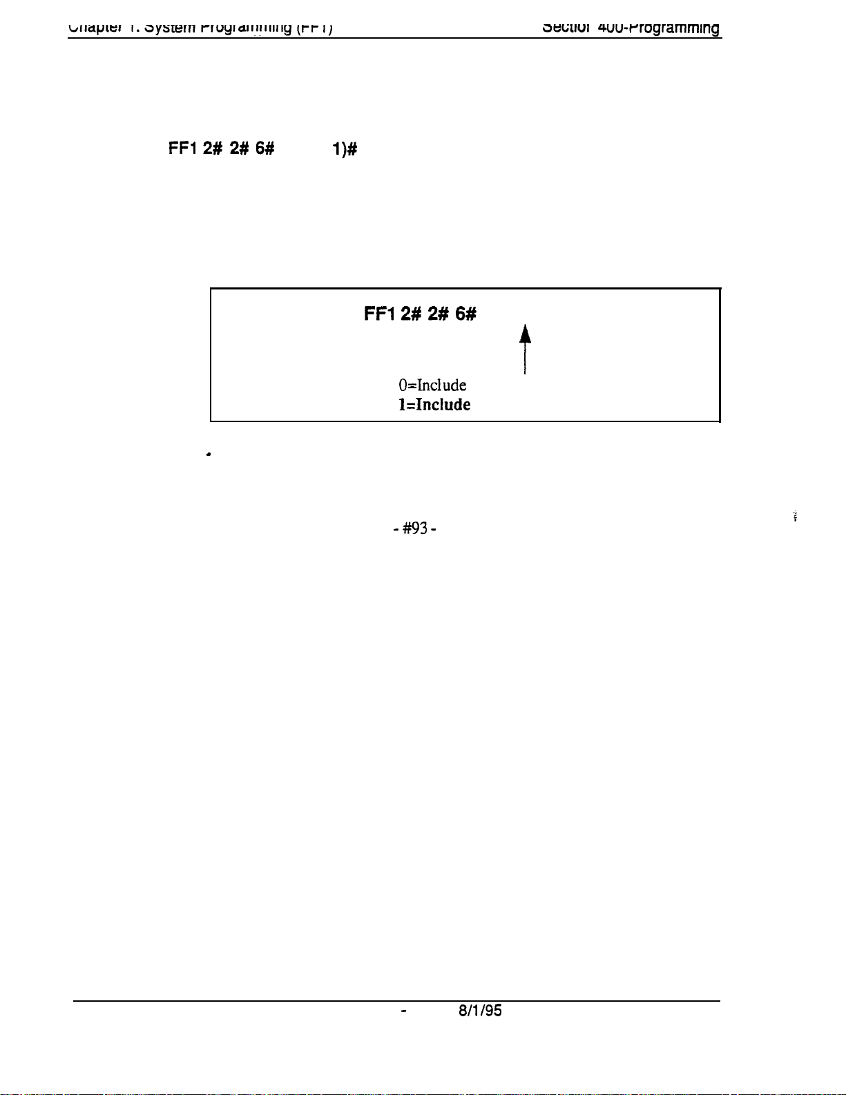
3twu1
I
4uu-rrogrammlng
SMDR Printing Mode 1: Outbound and Inbound
Software Version: All Versions
Address:
FFl 2# 2# 6#
(0 or
l)#
Description
Programming
Notes
The SMDR data sent to Serial Port CN6 can be programmed to include both
outbound and inbound calls, or it can be limited to outbound calls only. By
default, both outbound and inbound calls are recorded.
FFl 2# 2# 6#
(0 or 1 )#
t
O=Include
Hnclude
a
Bus Monitor Mode Interaction.
outbound calls only.
both inbound and outbound calls.
If the DBS is switched to Bus Monitor
mode for troubleshooting, the SMDR mode must be reactivated to resume
SMDR output. The SMDR mode can be reactivated from any Attendant
phone by pressing ON/OFF -
#93 -
ON/OFF.
Page 1-58
Technical Manuals Online! - http://www.tech-man.com
DBS Manual - Issued
8/l/95
DBS-70-400
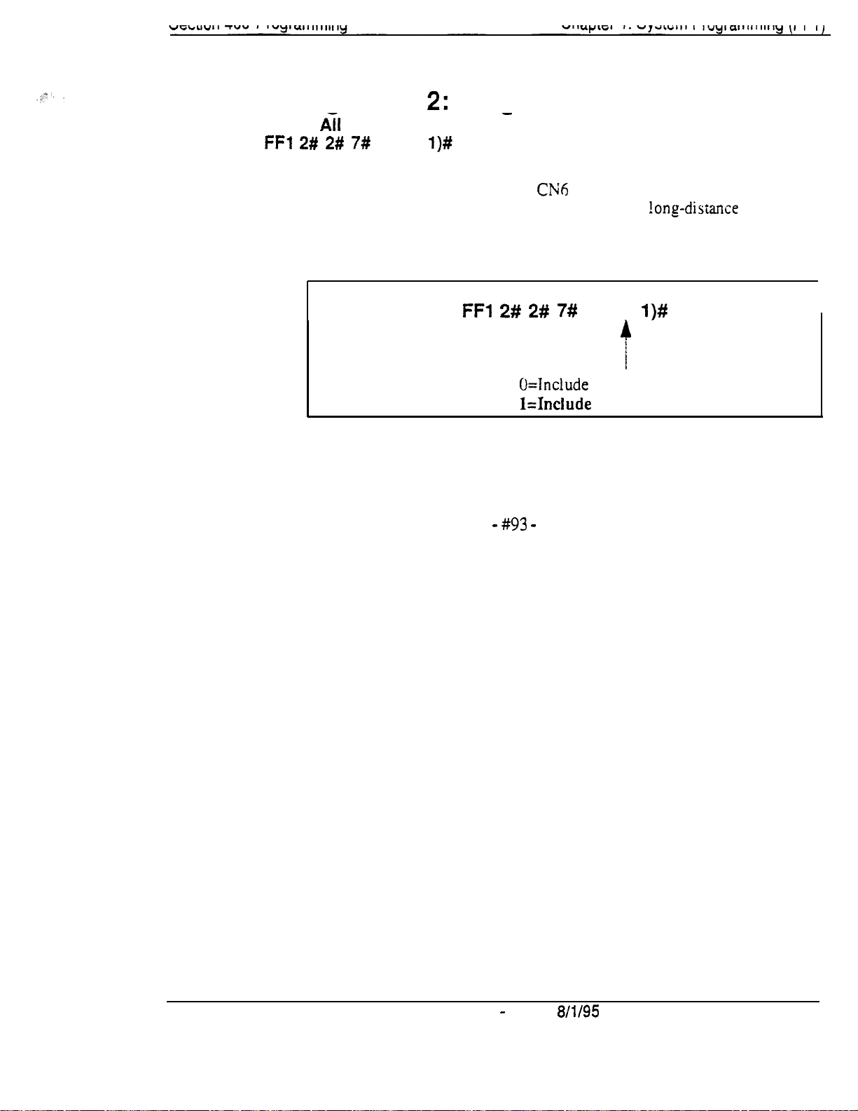
SMDR Printing Mode 2: Long-Distance and Local Calls
Software Version:
Address:
FFl 2# 2# 7#
fii
Versions
(0 or
l)#
-
Description The SMDR data sent to Serial Port
local and long-distance calls. or it can be limited to
By default, both local and long-distance calls are included.
Programming .
FFl 2# 2# 7#
U=Tnclude
Mnclude
Notes
Bus Monitor Mode Interaction.
mode for troubleshooting, the SMDR mode must be reactivated to resume
SMDR output. The SMDR mode can be reactivated from any Attendant
phone by pressing ON/OFF -
#93 -
CNh
can be pro&rarnmed to include both
!ong-distance
(0 or
long-distance calls only.
l)#
calls only.
local and long-distance calls.
If the DBS is switched to Bus Monitor
ON/OFF.
DBS-70-400
Technical Manuals Online! - http://www.tech-man.com
DBS Manual - issued
8/l/95
Page 1-59
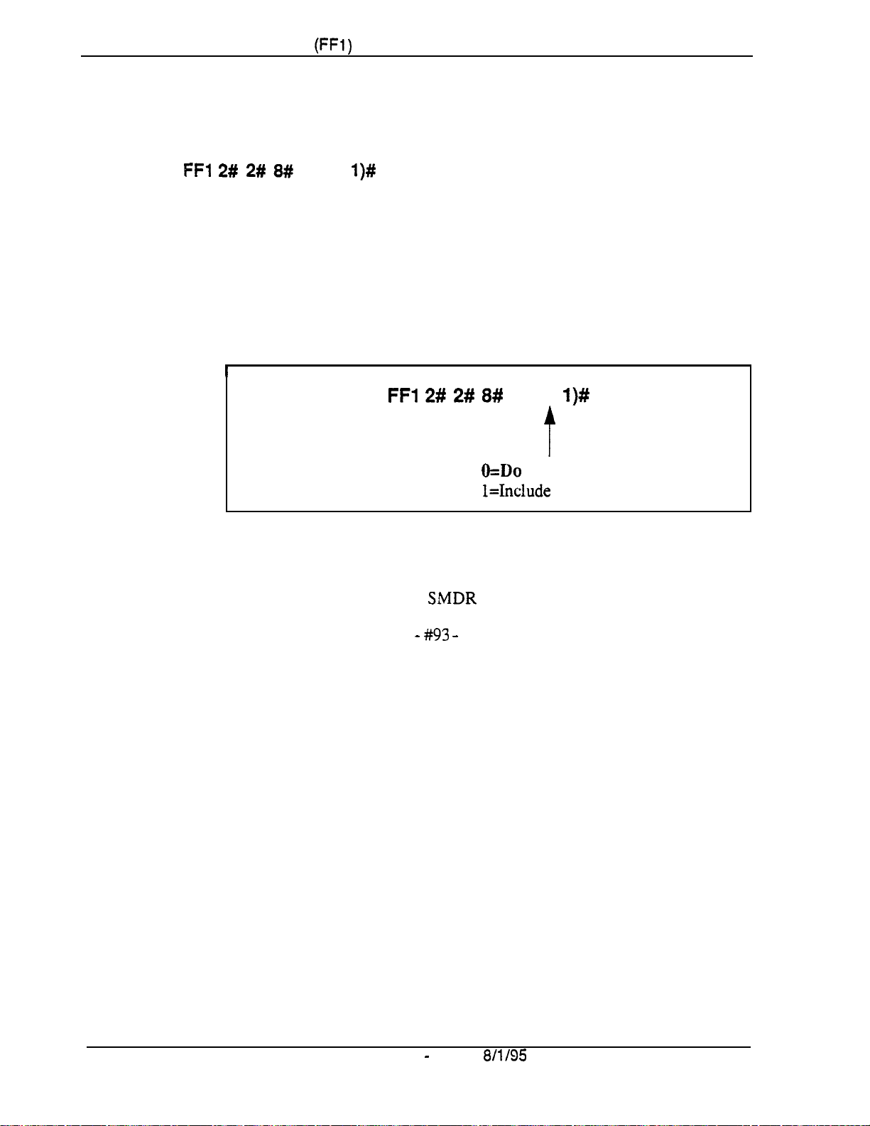
Chapter 1. System Programming
(FFl)
SMDR Printing Mode 3: Header Title
Software Version: All Versions
Address:
FFl 2# 2# 8#
(0 or
l)#
Section 400-Programming
Description
Programming
Notes
The SMDR data sent to Serial Port CN6 can be programmed to include a
header title (inserted every 60 lines on the SMDR report); or the header title
can be excluded from the report. By default, the header title is excluded.
The header title identifies the SMDR information in each column on the
report -- “Time,” “Duration,” “COW, etc.
I
FFl 2# 2# 8#
Bus Monitor Mode Interaction.
mode for troubleshooting, the SMDR mode must be reactivated to resume
SMDR output, The SMDR mode can be reactivated from any Attendant
phone by pressing ON/OFF -
If the DBS is switched to Bus Monitor
#93 -
ON/OFF.
(0 or
&Do
l=Include the header title.
l)#
t
not include the header title.
Page l-60
Technical Manuals Online! - http://www.tech-man.com
DBS Manual - Issued
8/l/95
DBS-70-400
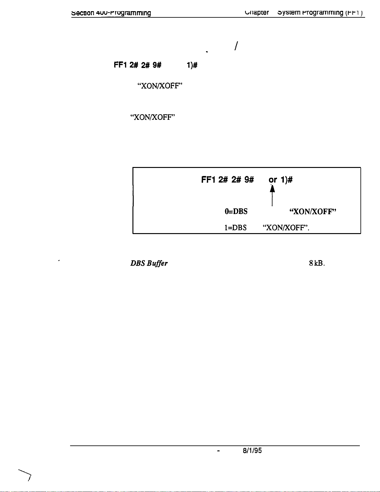
wcnon 4uu-rwgramming
briaprer
I.
3ysrem rrogrammlng (t-t1 )
Serial Port Flow Control (XON
Software Version: All Versions
Address:
Description
FFl 2# 2# 9#
If “XON/XOFF” is activated in this address, the DBS will stop the flow of
data when the SMDR device’s memory buffer becomes full, and resume the
flow when the buffer empties.
“XON/XOFF” should be deactivated (default setting) if a flow control
mechanism is present elsewhere in the interface (i.e., in the printer, or RTS
and CTS lines). A flow control mechanism should always be present in order
to prevent data from being lost during transmission.
(0 or
l)#
/
XOFF)
Programming
FFl 2# 2# 9#
O=DBS does
(flow control is present elsewhere).
l=DBS
(0 0’
not use
uses
“XON/XOFF’.
I)#
‘6XON/XOFF’
’
Notes
DBS
Buffer
maximum amount of data that the system can hold while the SMDR device is
emptying its buffer.
Size. The size of the DBS buffer for SMDR is 8
kB.
This is the
DBS-70-400 DBS Manual - Issued
Technical Manuals Online! - http://www.tech-man.com
8/l/95
Page 1-61
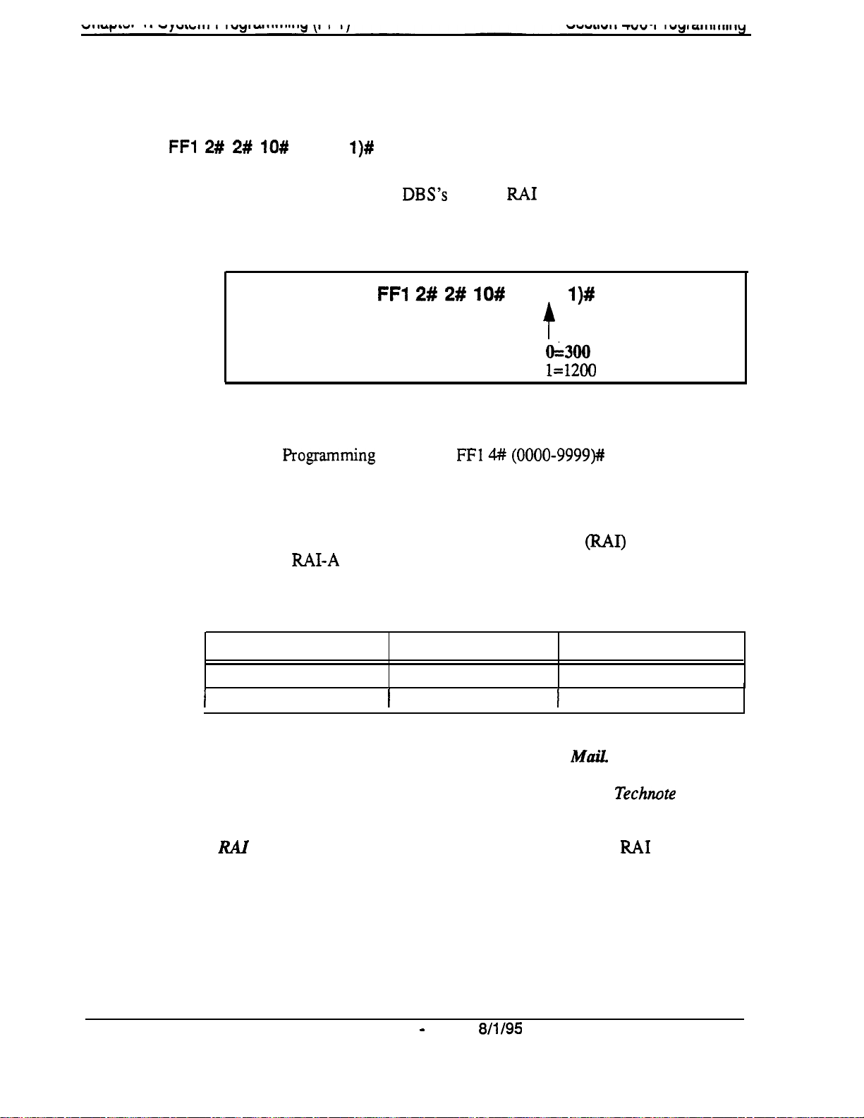
RAI Baud Rate
Software Version: CPC-All (all versions); CPC-B Version 1.0 or higher
Address:
FFl 2# 2# lO#
(0 or
l)#
Description
The baud rate used for the
1200 bps. By default, 300 bps is used for remote programming.
Programming
Related Programming
Notes
Remote
Modem Card Requirement for Remote Programming.
programming is provided through a modem card installed on the SCC card.
Two versions of the Remote Administration Interface (RAI) modem card are
available:
rate of each card, along with the SCC version with which it can be used:
Progamming
I&AI-A
and RAI-B.
DBS’s
internal
FFl 2# 2# lO#
ID Code:
FFl 4# (0000-9999)#
The following table shows the transmission
RAI
modem can be set to 300 or
(0 or
l)#
f
0=300 bps
1=1200
bus
Remote
Table 14.
RAI Modem Card Compatibility
RAI Version/Part No.
RAI-A (VB-43706)
/
RAI-B (VB-43707)
Restrictions for Two-Cabinet Systems Using Voice
1
300 or 1200
DES systems that have a Voice Mail system connected to an analog extension
port, the RAI card’s baud rate must be set to 300 bps. See
1991) for complete information.
RAI
Data Communications Parameters.
CPC-A, set the Serial Port parameters as follows:
l Parity: None
l
Data Length: 8 bits
l
Stop Bit Length: 1 bit
In CPC-B configurations, the DBS will automatically set these parameters for
the RAI card.
Transmission Rate
300 bps
bps
When using the
SCC Compatibility
SCC-A or SCC-B
1
SCC-B
Mail
only
In dual-cabinet
Technote
lU1
3 (April
card with
Page l-62
Technical Manuals Online! - http://www.tech-man.com
DBS Manual - Issued
8/l/95
DBS-70-400
 Loading...