

Page 1
Panasonic
a
DBS 824
Section 700
Feature
Operation
(Applies to CPC-S Version 3.0
and CPC-M Version 3.2)
Doc. No. 550X03601A
Version 3.0/3.2
Issued April 2000
Page 2
Warning:
cians only and is not design ed for use by the genera l publi c. It does not contain
warnings or cauti ons to advise non-t ec hni cal i ndi vi duals of potentia l dan ger s in
attempting to service a product. Products powered by electricity should be serviced or repaired only by exp erien ced profe ssion al techn ician s. Any attempt to
service or repair the product or products dealt with in this service information
by anyone else could result in serious injury or death.
This service information is designed for experienced repair techni-
FCC Warning
This equipment generates, uses, and can radiate radio frequency energy, and, if not installed
and used in accordance with the instruction manual, may cause interference to radio communications. This equipment has been tested and found to comply with the limits for a Class A
digital device pursuant to Part 15 of FCC Rules, which are designed to provide reasonable
protection against such interference when operated in a commercial environment. Operation
of this equipment in a residential area is likely to cause interference, in which case the user
at his own expense will be required to take necessary measures to correct the interference.
Battery Recyclin g Statement
The following statement applies if you purchased backup batteries with your system.
The product you have purchased contains rechargeable batteries. The batteries are recycla-
ble. At the end of their useful life, under various state and local laws, it may be illegal to dispose of these batteries into the municipal waste stream. Check with your local solid waste
officials for details on recycling options or proper disposal.
The information contained in this document is subject to change without notice and should not be
construed as a commitment by the Panasonic Telecommunication Systems Company (PTSC).
PTSC reserves the right, without notice, to make changes to equipment design as advances in
engineering and manufacturing methods warrant.
The software and hardware described in this document may be used or copied only in accordance
with the terms of the license pertaining to said software or hardware.
Reproduction, publication, or duplication of this manual, or any part thereof, in any manner,
mechanically, electronically, or photographically, is prohibited without permission of the
Panasonic Telecommunication Systems Company (PTSC).
Copyright 1995 by Panasonic Telecommunication Systems Company (PTSC)
Revised in April 2000.
All rights reserved.
ii
Page 3

iii
Page 4

Contents
About This Manual . . . . . . . . . . . . . . . . . . . . . . . . . . . . . . . . . . . . . . . . ix
List of Features . . . . . . . . . . . . . . . . . . . . . . . . . . . . . . . . . . . . . . . . . . . . . . . . . . . . xi
Chapter 1. System Features . . . . . . . . . . . . . . . . . . . . . . . . . . . . . . . 1-1
Account Codes. . . . . . . . . . . . . . . . . . . . . . . . . . . . . . . . . . . . . . . . . . . . . . . . . . . . 1-3
Non-Verified Account Codes . . . . . . . . . . . . . . . . . . . . . . . . . . . . . . . . . . . . . . . . . . . . . 1-3
Verified Account Codes . . . . . . . . . . . . . . . . . . . . . . . . . . . . . . . . . . . . . . . . . . . . . . . . . 1-4
Answer Supervision for Voice Mail . . . . . . . . . . . . . . . . . . . . . . . . . . . . . . . . . . . 1-6
Auto Day Mode. . . . . . . . . . . . . . . . . . . . . . . . . . . . . . . . . . . . . . . . . . . . . . . . . . . . 1-7
Auto Set Relocation. . . . . . . . . . . . . . . . . . . . . . . . . . . . . . . . . . . . . . . . . . . . . . . . 1-8
Background Music. . . . . . . . . . . . . . . . . . . . . . . . . . . . . . . . . . . . . . . . . . . . . . . . 1-10
Battery Alarm . . . . . . . . . . . . . . . . . . . . . . . . . . . . . . . . . . . . . . . . . . . . . . . . . . . . 1-11
Battery Backup. . . . . . . . . . . . . . . . . . . . . . . . . . . . . . . . . . . . . . . . . . . . . . . . . . . 1-12
Call Forward ID Code for Voice Mail . . . . . . . . . . . . . . . . . . . . . . . . . . . . . . . . . 1-12
Caller ID . . . . . . . . . . . . . . . . . . . . . . . . . . . . . . . . . . . . . . . . . . . . . . . . . . . . . . . . 1-13
Caller ID Call Log. . . . . . . . . . . . . . . . . . . . . . . . . . . . . . . . . . . . . . . . . . . . . . . . . 1-13
Centrex/PBX Compatibility. . . . . . . . . . . . . . . . . . . . . . . . . . . . . . . . . . . . . . . . . 1-14
Direct Inward System Access (DISA). . . . . . . . . . . . . . . . . . . . . . . . . . . . . . . . . 1-14
Direct Trunk Access . . . . . . . . . . . . . . . . . . . . . . . . . . . . . . . . . . . . . . . . . . . . . . 1-17
Distinctive Ringing . . . . . . . . . . . . . . . . . . . . . . . . . . . . . . . . . . . . . . . . . . . . . . . 1-17
Door Box. . . . . . . . . . . . . . . . . . . . . . . . . . . . . . . . . . . . . . . . . . . . . . . . . . . . . . . . 1-18
DP to DTMF Signal Conversion . . . . . . . . . . . . . . . . . . . . . . . . . . . . . . . . . . . . . 1-20
Hunting Priority for VAUs . . . . . . . . . . . . . . . . . . . . . . . . . . . . . . . . . . . . . . . . . . 1-21
Independent Timers. . . . . . . . . . . . . . . . . . . . . . . . . . . . . . . . . . . . . . . . . . . . . . . 1-22
Least Cost Routing (LCR). . . . . . . . . . . . . . . . . . . . . . . . . . . . . . . . . . . . . . . . . . 1-23
Music-on-Hold . . . . . . . . . . . . . . . . . . . . . . . . . . . . . . . . . . . . . . . . . . . . . . . . . . . 1-24
Night Service . . . . . . . . . . . . . . . . . . . . . . . . . . . . . . . . . . . . . . . . . . . . . . . . . . . . 1-25
Off-Premises Ex tension . . . . . . . . . . . . . . . . . . . . . . . . . . . . . . . . . . . . . . . . . . . 1-27
Paging. . . . . . . . . . . . . . . . . . . . . . . . . . . . . . . . . . . . . . . . . . . . . . . . . . . . . . . . . . 1-28
Power Failure Transfer . . . . . . . . . . . . . . . . . . . . . . . . . . . . . . . . . . . . . . . . . . . . 1-29
Remote Maintenance. . . . . . . . . . . . . . . . . . . . . . . . . . . . . . . . . . . . . . . . . . . . . . 1-31
Remote Programming Mode . . . . . . . . . . . . . . . . . . . . . . . . . . . . . . . . . . . . . . . . . . . . 1-31
Station Class of Service . . . . . . . . . . . . . . . . . . . . . . . . . . . . . . . . . . . . . . . . . . . 1-33
Station Hunting . . . . . . . . . . . . . . . . . . . . . . . . . . . . . . . . . . . . . . . . . . . . . . . . . . 1-34
Station Message Detail Recording (SMDR). . . . . . . . . . . . . . . . . . . . . . . . . . . . 1-37
Toll Restriction. . . . . . . . . . . . . . . . . . . . . . . . . . . . . . . . . . . . . . . . . . . . . . . . . . . 1-38
Trunk Groups. . . . . . . . . . . . . . . . . . . . . . . . . . . . . . . . . . . . . . . . . . . . . . . . . . . . 1-40
Trunk Name Assignment. . . . . . . . . . . . . . . . . . . . . . . . . . . . . . . . . . . . . . . . . . . 1-41
Trunk Queuing . . . . . . . . . . . . . . . . . . . . . . . . . . . . . . . . . . . . . . . . . . . . . . . . . . . 1-42
Universal Night Answer. . . . . . . . . . . . . . . . . . . . . . . . . . . . . . . . . . . . . . . . . . . . 1-43
Voice Mail Ringing. . . . . . . . . . . . . . . . . . . . . . . . . . . . . . . . . . . . . . . . . . . . . . . . 1-44
Revised April 2000 DBS 824-3.0/3.2-700 iii
Page 5

VAU . . . . . . . . . . . . . . . . . . . . . . . . . . . . . . . . . . . . . . . . . . . . . . . . . . . . . . . . . . . . 1-45
VAU Port Assignment . . . . . . . . . . . . . . . . . . . . . . . . . . . . . . . . . . . . . . . . . . . . . 1-45
Walking TRS Class of Service . . . . . . . . . . . . . . . . . . . . . . . . . . . . . . . . . . . . . . 1-46
Chapter 2. Attendant Features . . . . . . . . . . . . . . . . . . . . . . . . . . . . . 2-1
Attendant Assignment of Speed Dialing. . . . . . . . . . . . . . . . . . . . . . . . . . . . . . . 2-3
Attendant Busy Override. . . . . . . . . . . . . . . . . . . . . . . . . . . . . . . . . . . . . . . . . . . . 2-4
Attendant Call Park . . . . . . . . . . . . . . . . . . . . . . . . . . . . . . . . . . . . . . . . . . . . . . . . 2-5
Attendant Control of Absence Messages,. . . . . . . . . . . . . . . . . . . . . . . . . . . . . . 2-6
Attendant-Controlled Text Assignment. . . . . . . . . . . . . . . . . . . . . . . . . . . . . . . . 2-7
Attendant Groups . . . . . . . . . . . . . . . . . . . . . . . . . . . . . . . . . . . . . . . . . . . . . . . . . 2-9
Dial Tone Disable. . . . . . . . . . . . . . . . . . . . . . . . . . . . . . . . . . . . . . . . . . . . . . . . . 2-10
DSS/72. . . . . . . . . . . . . . . . . . . . . . . . . . . . . . . . . . . . . . . . . . . . . . . . . . . . . . . . . . 2-11
Headset Operation. . . . . . . . . . . . . . . . . . . . . . . . . . . . . . . . . . . . . . . . . . . . . . . . 2-13
Key Bank Hold . . . . . . . . . . . . . . . . . . . . . . . . . . . . . . . . . . . . . . . . . . . . . . . . . . . 2-14
One-Touch VM Transfer . . . . . . . . . . . . . . . . . . . . . . . . . . . . . . . . . . . . . . . . . . . 2-14
Station Lockout Code Assignment . . . . . . . . . . . . . . . . . . . . . . . . . . . . . . . . . . 2-17
System Time and Date Control. . . . . . . . . . . . . . . . . . . . . . . . . . . . . . . . . . . . . . 2-18
Traffic Measurement . . . . . . . . . . . . . . . . . . . . . . . . . . . . . . . . . . . . . . . . . . . . . . 2-20
Walking COS Confirmation. . . . . . . . . . . . . . . . . . . . . . . . . . . . . . . . . . . . . . . . . 2-22
Chapter 3. Key Telephone Features. . . . . . . . . . . . . . . . . . . . . . . . . 3-1
Key Phone . . . . . . . . . . . . . . . . . . . . . . . . . . . . . . . . . . . . . . . . . . . . . . . . . . . . . . . 3-3
Absence Message . . . . . . . . . . . . . . . . . . . . . . . . . . . . . . . . . . . . . . . . . . . . . . . . . 3-3
Auto Redial. . . . . . . . . . . . . . . . . . . . . . . . . . . . . . . . . . . . . . . . . . . . . . . . . . . . . . . 3-6
Auto-Repeat Dial . . . . . . . . . . . . . . . . . . . . . . . . . . . . . . . . . . . . . . . . . . . . . . . . . . 3-7
Busy Override . . . . . . . . . . . . . . . . . . . . . . . . . . . . . . . . . . . . . . . . . . . . . . . . . . . . 3-7
Call Coverage Groups. . . . . . . . . . . . . . . . . . . . . . . . . . . . . . . . . . . . . . . . . . . . . . 3-8
Call Duration Display. . . . . . . . . . . . . . . . . . . . . . . . . . . . . . . . . . . . . . . . . . . . . . 3-10
Call Forwarding . . . . . . . . . . . . . . . . . . . . . . . . . . . . . . . . . . . . . . . . . . . . . . . . . . 3-10
Call Hold . . . . . . . . . . . . . . . . . . . . . . . . . . . . . . . . . . . . . . . . . . . . . . . . . . . . . . . . 3-14
Exclusive Hold . . . . . . . . . . . . . . . . . . . . . . . . . . . . . . . . . . . . . . . . . . . . . . . . . . . . . . . 3-14
System Hold. . . . . . . . . . . . . . . . . . . . . . . . . . . . . . . . . . . . . . . . . . . . . . . . . . . . . . . . . 3-15
Call Park . . . . . . . . . . . . . . . . . . . . . . . . . . . . . . . . . . . . . . . . . . . . . . . . . . . . . . . . 3-17
Call Pickup . . . . . . . . . . . . . . . . . . . . . . . . . . . . . . . . . . . . . . . . . . . . . . . . . . . . . . 3-19
Group Call Pickup . . . . . . . . . . . . . . . . . . . . . . . . . . . . . . . . . . . . . . . . . . . . . . . . . . . . 3-20
Call Transfer. . . . . . . . . . . . . . . . . . . . . . . . . . . . . . . . . . . . . . . . . . . . . . . . . . . . . 3-21
Blind Transfer. . . . . . . . . . . . . . . . . . . . . . . . . . . . . . . . . . . . . . . . . . . . . . . . . . . . . . . . 3-21
Screened Transfer. . . . . . . . . . . . . . . . . . . . . . . . . . . . . . . . . . . . . . . . . . . . . . . . . . . . 3-23
Call Waiting . . . . . . . . . . . . . . . . . . . . . . . . . . . . . . . . . . . . . . . . . . . . . . . . . . . . . 3-25
Call Waiting/OHVA Text Reply . . . . . . . . . . . . . . . . . . . . . . . . . . . . . . . . . . . . . . 3-28
Camp-on . . . . . . . . . . . . . . . . . . . . . . . . . . . . . . . . . . . . . . . . . . . . . . . . . . . . . . . . 3-29
CO Line Key Trunk Access. . . . . . . . . . . . . . . . . . . . . . . . . . . . . . . . . . . . . . . . . 3-30
Conference Calls . . . . . . . . . . . . . . . . . . . . . . . . . . . . . . . . . . . . . . . . . . . . . . . . . 3-31
iv DBS 824-3.0/3 .2-700 Revised April 2000
Page 6

Delayed Ringing. . . . . . . . . . . . . . . . . . . . . . . . . . . . . . . . . . . . . . . . . . . . . . . . . . 3-33
Dial “0” for Attendant . . . . . . . . . . . . . . . . . . . . . . . . . . . . . . . . . . . . . . . . . . . . . 3-34
Do-Not-Disturb (DND) . . . . . . . . . . . . . . . . . . . . . . . . . . . . . . . . . . . . . . . . . . . . . 3-35
EM/24 Console . . . . . . . . . . . . . . . . . . . . . . . . . . . . . . . . . . . . . . . . . . . . . . . . . . . 3-36
Flexible Function (FF) Keys . . . . . . . . . . . . . . . . . . . . . . . . . . . . . . . . . . . . . . . . 3-37
Handsfree Answerback. . . . . . . . . . . . . . . . . . . . . . . . . . . . . . . . . . . . . . . . . . . . 3-42
Handsfree Operation. . . . . . . . . . . . . . . . . . . . . . . . . . . . . . . . . . . . . . . . . . . . . . 3-43
Headset Operation. . . . . . . . . . . . . . . . . . . . . . . . . . . . . . . . . . . . . . . . . . . . . . . . 3-43
Intercom Calling. . . . . . . . . . . . . . . . . . . . . . . . . . . . . . . . . . . . . . . . . . . . . . . . . . 3-43
Last Number Redial. . . . . . . . . . . . . . . . . . . . . . . . . . . . . . . . . . . . . . . . . . . . . . . 3-46
Line Appearances . . . . . . . . . . . . . . . . . . . . . . . . . . . . . . . . . . . . . . . . . . . . . . . . 3-47
DSS/BLF Appearances . . . . . . . . . . . . . . . . . . . . . . . . . . . . . . . . . . . . . . . . . . . . . . . . 3-48
Multi-CO (MCO) Appearances. . . . . . . . . . . . . . . . . . . . . . . . . . . . . . . . . . . . . . . . . . . 3-51
Multi-Line (ML) Appearances. . . . . . . . . . . . . . . . . . . . . . . . . . . . . . . . . . . . . . . . . . . . 3-53
ML/MCO Separation. . . . . . . . . . . . . . . . . . . . . . . . . . . . . . . . . . . . . . . . . . . . . . . 3-54
Meet-Me Answer. . . . . . . . . . . . . . . . . . . . . . . . . . . . . . . . . . . . . . . . . . . . . . . . . . 3-54
Message Waiting/Callback Request. . . . . . . . . . . . . . . . . . . . . . . . . . . . . . . . . . 3-55
Non-Appearing Outside Lines . . . . . . . . . . . . . . . . . . . . . . . . . . . . . . . . . . . . . . 3-58
Offhook Signaling . . . . . . . . . . . . . . . . . . . . . . . . . . . . . . . . . . . . . . . . . . . . . . . . 3-59
Offhook Voice Announce (OHVA) . . . . . . . . . . . . . . . . . . . . . . . . . . . . . . . . . . . 3-60
One-Touch Keys . . . . . . . . . . . . . . . . . . . . . . . . . . . . . . . . . . . . . . . . . . . . . . . . . 3-62
One-Touch VM Access . . . . . . . . . . . . . . . . . . . . . . . . . . . . . . . . . . . . . . . . . . . . 3-65
Onhook Dialing . . . . . . . . . . . . . . . . . . . . . . . . . . . . . . . . . . . . . . . . . . . . . . . . . . 3-67
Pooled Trunk Access . . . . . . . . . . . . . . . . . . . . . . . . . . . . . . . . . . . . . . . . . . . . . 3-68
Prime Line Preference. . . . . . . . . . . . . . . . . . . . . . . . . . . . . . . . . . . . . . . . . . . . . 3-70
Private Line. . . . . . . . . . . . . . . . . . . . . . . . . . . . . . . . . . . . . . . . . . . . . . . . . . . . . . 3-71
Reminder Call. . . . . . . . . . . . . . . . . . . . . . . . . . . . . . . . . . . . . . . . . . . . . . . . . . . . 3-72
Ringing Line Preference . . . . . . . . . . . . . . . . . . . . . . . . . . . . . . . . . . . . . . . . . . . 3-73
Saved Number Redial . . . . . . . . . . . . . . . . . . . . . . . . . . . . . . . . . . . . . . . . . . . . . 3-74
Speed Dialing. . . . . . . . . . . . . . . . . . . . . . . . . . . . . . . . . . . . . . . . . . . . . . . . . . . . 3-75
System Speed Dial . . . . . . . . . . . . . . . . . . . . . . . . . . . . . . . . . . . . . . . . . . . . . . . . . . . 3-78
Speed Dial Linking. . . . . . . . . . . . . . . . . . . . . . . . . . . . . . . . . . . . . . . . . . . . . . . . . . . . 3-80
Station Lockout . . . . . . . . . . . . . . . . . . . . . . . . . . . . . . . . . . . . . . . . . . . . . . . . . . 3-81
Trunk-to-Trunk Transfer . . . . . . . . . . . . . . . . . . . . . . . . . . . . . . . . . . . . . . . . . . . 3-82
Chapter 4. DSLT Features. . . . . . . . . . . . . . . . . . . . . . . . . . . . . . . . . 4-1
DSLT . . . . . . . . . . . . . . . . . . . . . . . . . . . . . . . . . . . . . . . . . . . . . . . . . . . . . . . . . . . . 4-3
Absence Message . . . . . . . . . . . . . . . . . . . . . . . . . . . . . . . . . . . . . . . . . . . . . . . . . 4-3
Busy Override . . . . . . . . . . . . . . . . . . . . . . . . . . . . . . . . . . . . . . . . . . . . . . . . . . . . 4-5
Call Forwarding . . . . . . . . . . . . . . . . . . . . . . . . . . . . . . . . . . . . . . . . . . . . . . . . . . . 4-6
Call Hold . . . . . . . . . . . . . . . . . . . . . . . . . . . . . . . . . . . . . . . . . . . . . . . . . . . . . . . . . 4-9
Call Park . . . . . . . . . . . . . . . . . . . . . . . . . . . . . . . . . . . . . . . . . . . . . . . . . . . . . . . . 4-10
Call Pickup . . . . . . . . . . . . . . . . . . . . . . . . . . . . . . . . . . . . . . . . . . . . . . . . . . . . . . 4-12
Direct Call Pickup. . . . . . . . . . . . . . . . . . . . . . . . . . . . . . . . . . . . . . . . . . . . . . . . . . . . . 4-12
Group Call Pickup . . . . . . . . . . . . . . . . . . . . . . . . . . . . . . . . . . . . . . . . . . . . . . . . . . . . 4-13
Revised April 2000 DBS 824-3.0/3.2-700 v
Page 7

Call Transfer. . . . . . . . . . . . . . . . . . . . . . . . . . . . . . . . . . . . . . . . . . . . . . . . . . . . . 4-14
Blind Transfer. . . . . . . . . . . . . . . . . . . . . . . . . . . . . . . . . . . . . . . . . . . . . . . . . . . . . . . . 4-14
Screened Transfer. . . . . . . . . . . . . . . . . . . . . . . . . . . . . . . . . . . . . . . . . . . . . . . . . . . . 4-15
Call Waiting . . . . . . . . . . . . . . . . . . . . . . . . . . . . . . . . . . . . . . . . . . . . . . . . . . . . . 4-16
Camp-on . . . . . . . . . . . . . . . . . . . . . . . . . . . . . . . . . . . . . . . . . . . . . . . . . . . . . . . . 4-18
Conference Calls . . . . . . . . . . . . . . . . . . . . . . . . . . . . . . . . . . . . . . . . . . . . . . . . . 4-20
Dial “0” for Attendant . . . . . . . . . . . . . . . . . . . . . . . . . . . . . . . . . . . . . . . . . . . . . 4-21
Direct Trunk Access . . . . . . . . . . . . . . . . . . . . . . . . . . . . . . . . . . . . . . . . . . . . . . 4-21
Do-Not-Disturb (DND) . . . . . . . . . . . . . . . . . . . . . . . . . . . . . . . . . . . . . . . . . . . . . 4-22
Intercom Calling. . . . . . . . . . . . . . . . . . . . . . . . . . . . . . . . . . . . . . . . . . . . . . . . . . 4-23
Last Number Redial. . . . . . . . . . . . . . . . . . . . . . . . . . . . . . . . . . . . . . . . . . . . . . . 4-24
Meet-Me Answer. . . . . . . . . . . . . . . . . . . . . . . . . . . . . . . . . . . . . . . . . . . . . . . . . . 4-25
Message Waiting/Callback Request. . . . . . . . . . . . . . . . . . . . . . . . . . . . . . . . . . 4-26
Off-Hook Voice Announce (OHVA). . . . . . . . . . . . . . . . . . . . . . . . . . . . . . . . . . . 4-27
Onhook Dialing . . . . . . . . . . . . . . . . . . . . . . . . . . . . . . . . . . . . . . . . . . . . . . . . . . 4-29
Pooled Trunk Access . . . . . . . . . . . . . . . . . . . . . . . . . . . . . . . . . . . . . . . . . . . . . 4-29
Reminder Call. . . . . . . . . . . . . . . . . . . . . . . . . . . . . . . . . . . . . . . . . . . . . . . . . . . . 4-30
Saved Number Redial . . . . . . . . . . . . . . . . . . . . . . . . . . . . . . . . . . . . . . . . . . . . . 4-31
Speed Dialing. . . . . . . . . . . . . . . . . . . . . . . . . . . . . . . . . . . . . . . . . . . . . . . . . . . . 4-32
Personal Speed Dialing . . . . . . . . . . . . . . . . . . . . . . . . . . . . . . . . . . . . . . . . . . . . . . . . 4-32
System Speed Dial . . . . . . . . . . . . . . . . . . . . . . . . . . . . . . . . . . . . . . . . . . . . . . . . . . . 4-33
Chapter 5. SLT Features . . . . . . . . . . . . . . . . . . . . . . . . . . . . . . . . . . 5-1
Absence Message . . . . . . . . . . . . . . . . . . . . . . . . . . . . . . . . . . . . . . . . . . . . . . . . . 5-3
Auto Redial. . . . . . . . . . . . . . . . . . . . . . . . . . . . . . . . . . . . . . . . . . . . . . . . . . . . . . . 5-5
Auto-Repeat Dial . . . . . . . . . . . . . . . . . . . . . . . . . . . . . . . . . . . . . . . . . . . . . . . . . . 5-5
Busy Override . . . . . . . . . . . . . . . . . . . . . . . . . . . . . . . . . . . . . . . . . . . . . . . . . . . . 5-6
Call Forwarding . . . . . . . . . . . . . . . . . . . . . . . . . . . . . . . . . . . . . . . . . . . . . . . . . . . 5-7
Call Hold . . . . . . . . . . . . . . . . . . . . . . . . . . . . . . . . . . . . . . . . . . . . . . . . . . . . . . . . 5-10
Call Park . . . . . . . . . . . . . . . . . . . . . . . . . . . . . . . . . . . . . . . . . . . . . . . . . . . . . . . . 5-11
Call Pickup . . . . . . . . . . . . . . . . . . . . . . . . . . . . . . . . . . . . . . . . . . . . . . . . . . . . . . 5-12
Direct Call Pickup. . . . . . . . . . . . . . . . . . . . . . . . . . . . . . . . . . . . . . . . . . . . . . . . . . . . . 5-12
Group Call Pickup . . . . . . . . . . . . . . . . . . . . . . . . . . . . . . . . . . . . . . . . . . . . . . . . . . . . 5-13
Call Transfer. . . . . . . . . . . . . . . . . . . . . . . . . . . . . . . . . . . . . . . . . . . . . . . . . . . . . 5-14
Blind Transfer. . . . . . . . . . . . . . . . . . . . . . . . . . . . . . . . . . . . . . . . . . . . . . . . . . . . . . . . 5-14
Screened Transfer. . . . . . . . . . . . . . . . . . . . . . . . . . . . . . . . . . . . . . . . . . . . . . . . . . . . 5-15
Call Waiting . . . . . . . . . . . . . . . . . . . . . . . . . . . . . . . . . . . . . . . . . . . . . . . . . . . . . 5-17
Camp-on . . . . . . . . . . . . . . . . . . . . . . . . . . . . . . . . . . . . . . . . . . . . . . . . . . . . . . . . 5-19
Conference Calls . . . . . . . . . . . . . . . . . . . . . . . . . . . . . . . . . . . . . . . . . . . . . . . . . 5-20
Dial “0” for Attendant . . . . . . . . . . . . . . . . . . . . . . . . . . . . . . . . . . . . . . . . . . . . . 5-21
DTMF Stations . . . . . . . . . . . . . . . . . . . . . . . . . . . . . . . . . . . . . . . . . . . . . . . . . . . 5-22
Direct Trunk Access . . . . . . . . . . . . . . . . . . . . . . . . . . . . . . . . . . . . . . . . . . . . . . 5-22
Do-Not-Disturb (DND) . . . . . . . . . . . . . . . . . . . . . . . . . . . . . . . . . . . . . . . . . . . . . 5-23
Intercom Calling. . . . . . . . . . . . . . . . . . . . . . . . . . . . . . . . . . . . . . . . . . . . . . . . . . 5-24
Last Number Redial. . . . . . . . . . . . . . . . . . . . . . . . . . . . . . . . . . . . . . . . . . . . . . . 5-25
vi DBS 824-3.0/3.2-700 Revised Apri l 2000
Page 8

Meet-Me Answer. . . . . . . . . . . . . . . . . . . . . . . . . . . . . . . . . . . . . . . . . . . . . . . . . . 5-26
Message Waiting/Callback Request. . . . . . . . . . . . . . . . . . . . . . . . . . . . . . . . . . 5-27
Offhook Voice Announce (OHVA) . . . . . . . . . . . . . . . . . . . . . . . . . . . . . . . . . . . 5-28
Pooled Trunk Access . . . . . . . . . . . . . . . . . . . . . . . . . . . . . . . . . . . . . . . . . . . . . 5-29
Speed Dialing. . . . . . . . . . . . . . . . . . . . . . . . . . . . . . . . . . . . . . . . . . . . . . . . . . . . 5-30
Personal Speed Dial . . . . . . . . . . . . . . . . . . . . . . . . . . . . . . . . . . . . . . . . . . . . . . . . . . 5-30
System Speed Dial . . . . . . . . . . . . . . . . . . . . . . . . . . . . . . . . . . . . . . . . . . . . . . . . . . . 5-31
Appendix A: 2.0 Feature Update. . . . . . . . . . . . . . . . . . . . . . . . . . . A-1
Contents . . . . . . . . . . . . . . . . . . . . . . . . . . . . . . . . . . . . . . . . . . . . . . . . . . . . . . . . . A-1
44-Series Phone Support . . . . . . . . . . . . . . . . . . . . . . . . . . . . . . . . . . . . . . . . . . . A-2
Added Features . . . . . . . . . . . . . . . . . . . . . . . . . . . . . . . . . . . . . . . . . . . . . . . . . . . A-3
Directory Mode. . . . . . . . . . . . . . . . . . . . . . . . . . . . . . . . . . . . . . . . . . . . . . . . . . . . . . . . A-7
Variable Mode . . . . . . . . . . . . . . . . . . . . . . . . . . . . . . . . . . . . . . . . . . . . . . . . . . . . . . . . A-8
Handset Mute. . . . . . . . . . . . . . . . . . . . . . . . . . . . . . . . . . . . . . . . . . . . . . . . . . . . . . . . A-10
Off-Hook Monitoring. . . . . . . . . . . . . . . . . . . . . . . . . . . . . . . . . . . . . . . . . . . . . . . . . . . A-11
Separate Speaker Volumes for Internal vs. CO calls. . . . . . . . . . . . . . . . . . . . . . . . . . A-11
Analog Adapter . . . . . . . . . . . . . . . . . . . . . . . . . . . . . . . . . . . . . . . . . . . . . . . . . . . . . . A-12
MSG (Message) Key . . . . . . . . . . . . . . . . . . . . . . . . . . . . . . . . . . . . . . . . . . . . . . . . . . A-14
DSS/72 Console - Key Arrangement. . . . . . . . . . . . . . . . . . . . . . . . . . . . . . . . . . . . . . A-16
EM/24 - Key Arrangement . . . . . . . . . . . . . . . . . . . . . . . . . . . . . . . . . . . . . . . . . . . . . . A-20
Modification to Toll Restriction Service . . . . . . . . . . . . . . . . . . . . . . . . . . . . . . A-22
Key Telephone Installation Notes . . . . . . . . . . . . . . . . . . . . . . . . . . . . . . . . . . . A-23
Desi Strip Cover. . . . . . . . . . . . . . . . . . . . . . . . . . . . . . . . . . . . . . . . . . . . . . . . . . . . . . A-23
Key Telephone Wall Mounting Instructi ons . . . . . . . . . . . . . . . . . . . . . . . . . . . . . . . . . A-23
Appendix B: 3.0 Feature Update . . . . . . . . . . . . . . . . . . . . . . . . . . . B-1
Appendix C: 3.1 Feature Update . . . . . . . . . . . . . . . . . . . . . . . . . . . C-1
Call Record . . . . . . . . . . . . . . . . . . . . . . . . . . . . . . . . . . . . . . . . . . . . . . . . . . . . . . C-1
Index . . . . . . . . . . . . . . . . . . . . . . . . . . . . . . . . . . . . . . . . . . . . . . . . . . .I-1
Revised April 2000 DBS 824-3.0/3.2-700 vii
Page 9

viii DBS 824-3.0/3 .2-700 Revised April 2000
Page 10
About This Manual
Software Versions Covered by This Manual
This manual covers all versions of the DBS 824.
Differences in feature availability or operation are noted within each feature
description.
If you are using this manual for a single DBS 824 system, make note of its
software version in the following table. This note may be referenced by
technicians or owners of the system.
Software version information for systems shipped with
this document
CPC-S Software Version __________
CPC-M Software Version __________
Organization
This manual contains detailed descriptions of DBS 824 features. The feature
descriptions are organized according to the following categories:
Feature Categories Description
System Features System Features are either available on a
system-wide basis or aid in the overall
administration of the DBS 824.
Attendant Features Attendant Features assist the attendant in
serving as a central answering point. In addition,
attendant features also provide special
capabilities for monitoring and programming
extensions.
Key Telephone
Features
Digital Single-Line
Telephone
(DSLT) Features
Key Telephone Features are available to DBS
key phones. DBS key phones are proprietary
digital sets that provide feature access through a
combination of feature keys and access codes.
DSLT Features are available to Digital SingleLine Telephones. DSLTs provide digital audio
quality and limited feature key access in a
single-line set.
Revised April 2000 DBS 824-3.0/3.2-700 ix
Page 11

Purpose
Single Line Telephone
Features
Appendices Descriptions of several feature upgrades have
The purpose of this manual is to provide an overview of feature operation and
requirements. Where applicable, the following types of information are
provided for each feature.
Types of information Purpose
Description The Description section provides an overview
Operation The Operation section includes step-by-step
SLT Features are available to industry-standard
2500 sets. Since SLTs are not equipped with
feature keys, most features are accessed by
using the dialpad and/or the switchhook.
been added to the Appendices of this manual.
Please refer to the Appendices when instructed
to do so.
of how the feature works and, in some cases,
what it is typically used for.
instructions on how to use the feature.
Hardware
Requirements
Related Programming The Related Programming section lists the
Considerations This section provides details on feature
This section lists any special hardware that is
required to use the feature.
programming subsystems associated with the
feature.
interactions and limitations.
x DBS 824-3.0/3.2-700 Revised April 2000
Page 12
About This Manual List
List of Features
The following tables list the features available with the DBS 824.
Topic Page
System Features xii
Attendant Features xiii
Extension Features xiv
Revised April 2000 DBS 824-3.0/3.2-700 xi
Page 13

List of Features
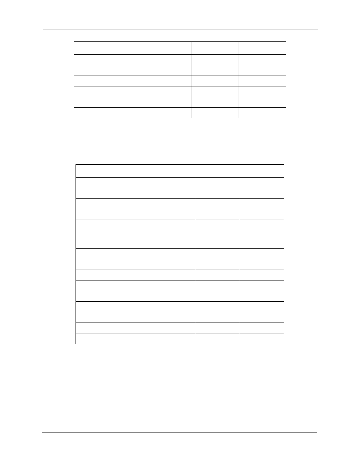
Table 1. System Features
Account Codes: Non-verified x x
Account Codes: Verified x x
Answer Supervision for Voice Mail x x
Auto Day Mode x x
Auto Set Relocation x x
Background Music x x
Battery Alarm x x
Battery Backup x x
Call Forward ID Code for Voice Mail x x
Centrex/PBX Compatibility x x
Direct Inward System Access (DISA) x x
Direct Trunk Access x x
Feature CPC-S CPC-M
Distinctive Ringing x x
Door Box x x
DP to DTMF Signal Conversion x x
Hunting Priority for VAUs x x
Independent Timers x x
Key Bank Hold x x
Least Cost Routing x x
Music-on-Hold x x
Music-on-Hold Internal Source x
Night Service (2 Modes) x x
Off-Premises Extension x x
Paging x x
Power Failure Transfer x x
Remote Maintenance x x
Station Class of Service x x
Station Hunting: Terminal, Distrib-
x x
uted, Longest Idle
Station Message Detail Recording
x x
(SMDR)
Toll Restriction x x
Trunk Groups x x
Trunk Name Assignment x x
xii DBS 824-3.0/3.2-700 Revised April 2000
Page 14
About This Manual List
Feature CPC-S CPC-M
Trunk Queuing x x
Universal Night Answer x
Voice Mail Ringing x x
VAU (Voice Announce Unit) x x
VAU Port Assignment x x
Walking TRS Class of Service x x
Table 2. Attendant Features
Feature CPC-S CPC-M
Alternate Attendant x x
Attendant Assignment of Speed Dialing x x
Attendant Busy Override x x
Attendant Call Park x x
Attendant Control of Absence Mes-
x x
sages, Call Forwarding, and DND
Attendant-Controlled Text Assignment x x
Attendant Groups x x
Dial Tone Disable x x
DSS/72 x x
Headset Operation x x
One-Touch VM Transfer x
Station Lockout Code Assignment x x
System Time and Date Control x x
Traffic Measurement x x
Walking COS Confirmation x x
x
Revised April 2000 DBS 824-3.0/3.2-700 xiii
Page 15

List of Features
Table 3. Extension Features
Absence Message x x
Feature CPC-S CPC-M
Auto-Repeat Dial
x x
Auto Redial x x
Busy Override
x x
Call Coverage Groups x x
Call Duration Display x x
Call Forwarding x x
Call Hold: Exclusive and System x x
Call Park x x
Call Pickup: Direct and Group x x
Call Transfer: Blind and Screened x x
Call Waiting x x
Call Waiting/OHVA Text Reply x x
Camp-on x x
CO Line Key Trunk Access x x
Conference Calls x x
Delayed Ringing x x
Dial “0” for Attendant x x
Direct Trunk Access x x
Do-Not-Disturb (DND) x x
EM/24 Console x x
Flexible Function (FF) Keys x x
Handsfree Answerback x x
Handsfree Operation
x x
Headset Operation x x
Intercom Calling x x
Last Number Redial
x x
Line Appearances x x
DSS/BLF Appearances: Direct Line
x x
(DL) Appearances
DSS/BLF Appearances: Multi-CO
x x
(MCO) Appearances
DSS/BLF Appearances: Multi-Line
x x
(ML) Appearances
xiv DBS 824-3.0/3.2-700 Revised April 2000
Page 16

About This Manual List
Feature CPC-S CPC-M
ML/MCO Separation x x
Meet-Me Answer x x
Message Waiting/Callback Request
Non-appearing Outside Line x x
Offhook Signaling
Off-Hook Voice Announce (OHVA) x x
One-Touch Keys x x
One-Touch VM Access x x
Onhook Dialing x x
Pooled Trunk Access x x
Prime Line Preference x x
Private Line x x
Reminder Call x x
Ringing Line Preference x x
Saved Number Redial x x
Speed Dial Linking x x
Speed Dialing: System and Personal x x
Speed Dialing Add-On Mode
(Expanded Range)
x x
x x
x
Station Lockout x x
Trunk-to-Trunk Transfer x x
Revised April 2000 DBS 824-3.0/3.2-700 xv
Page 17

List of Features
xvi DBS 824-3.0/3.2-700 Revised April 2000
Page 18

Chapter 1. System Features
This chapter contains detailed descriptions of DBS 824 System Features.
System Features are either available on a system-wide basis or aid in the
overall administration of the DBS 824.
This chapter covers the following topics:
Topic Page
Account Codes 1-3
Answer Supervision for Voice Mail 1-6
Auto Day Mode 1-7
Auto Set Relocation 1-8
Background Music 1-10
Battery Backup 1-12
Call Forward ID Code for Voice Mail 1-12
Caller ID 1-13
Direct Inward System Access (DISA) 1-14
Direct Trunk Access 1-17
Distinctive Ringing 1-17
Door Box 1-18
DP to DTMF Signal Conversion 1-20
DP to DTMF Signal Conversion 1-20
Hunting Priority for VAUs 1-21
Independent Timers 1-22
Least Cost Routing (LCR) 1-23
Music-on-Hold 1-24
Night Service 1-25
Off-Premises Extension 1-27
Paging 1-28
Power Failure Transfer 1-29
Remote Maintenance 1-31
Station Class of Service 1-33
Station Hunting 1-34
Station Message Detail Recording (SMDR) 1-37
Toll Restriction 1-38
Trunk Groups 1-40
Revised April 2000 DBS 824-3.0/3.2-700 1-1
Page 19

Topic Page
Trunk Name Assignment 1-41
Trunk Queuing 1-42
Universal Night Answer 1-43
Voice Mail Ringing 1-44
VAU 1-45
VAU Port Assignment 1-45
Walking TRS Class of Service 1-46
1-2 DBS 824-3.0/3.2-700 R evised April 2000
Page 20

System Features Account Codes
Account Codes
You can assign account codes to clients to facilitate billing and to track call
dates and times, numbers called, and outside line numbers used. This
information is printed for each account on the SMDR record.
Non-Verified Account Codes
(CPC-S and CPC-M)
Description
Non-verified account codes can be forced or voluntary, depending on
extension programming.
With voluntary account codes, the user is not forced to enter an account code
before making a call. With forced account codes, the user must enter an
account code before accessing an outside line.
Non-verified account codes can be assigned to incoming and outgoing calls.
To assign an account code to an outgoing call, the user enters the account
code before making the call or during the call. To assign an account code to
an incoming call, the user enters the account code during the call.
To enter an Account Code before dialing:
1. Press the
• The phone issues intercom dial tone.
• The
2. Press the
• “Enter Account #” appears on the display.
• If you are using a Single Line Telephone (SLT), dial “#7.”
3. Enter the Account Code (up to 10 digits).
4. Press “#.”
ON/OFF
ON/OFF
AUTO
key.
LED lights.
key, then press “#.”
“Entered Account #” appears on the display.
5. Press a vacant CO key or dial a trunk access code.
Revised April 2000 DBS 824-3.0/3.2-700 1-3
Page 21

Account Codes System Features
6. Dial the telephone number.
To enter an Account Code during an outside call:
1. Press the
2. Press “#.”
“Enter Account #” appears on the display.
3. Enter the Account Code (up to 10 digits).
The Account Code entered appears on the display.
4. Press “#.”
Hardware Requirements
• An SMDR printer or external call accounting system is required to collect
account code records.
Related Programming
• FF3 (Extension): Forced Account Codes
AUTO
key.
Considerations
• SLTs cannot assign account codes during a call.
Verified Account Codes
(CPC-S and CPC-M)
Description
Extensions with the Verified Account Codes feature enabled are restricted
from making outside calls without the user first entering a valid Account
Code. After a valid Account Code is entered, the Toll Restriction Service
(TRS) type assigned to the code is substituted for the extension TRS type,
thus temporarily allowing calls based on the new TRS type.
Extensions with the Verified Account Codes feature disabled can place
outside calls based on the TRS type assigned to the extension. If a user wishes
to place a call that would normally be restricted at the extension, the user can
1-4 DBS 824-3.0 /3.2-700 Revised April 2000
Page 22

System Features Account Codes
enter a valid Verified Account Code to upgrade the TRS type assigned to the
extension.
Operation
1. Pick up the handset.
The phone issues intercom dial tone.
2. Dial “#11.”
3. Enter the four-digit Account Code.
4. Press “#.”
The phone issues intercom dial tone.
5. Press an available CO key or dial a trunk access code.
The phone issues outside dial tone.
6. Dial the telephone number.
The Verified Account Code TRS type remains in effect until the call is
completed.
Related Programming
• FF1 (System): Verified Forced Account Codes
• FF1 (System): Toll Restriction for Verified Forced Account Codes
• FF3 (Extension): Forced Account Codes
• FF7 (TRS): Toll Restrictions
Hardware Requirements
• An SMDR printer or external call accounting system is required to collect
account code records.
Considerations
• Verified account codes are for outgoing calls only.
• The maximum number of verified account codes is 100.
• Each verified account code must consist of 4 digits.
Revised April 2000 DBS 824-3.0/3.2-700 1-5
Page 23

Answer Supervision for Voice Mail System Features
• “0000” cannot be used for a verified account code.
• Verified account codes do not override station lockout.
• Verified account codes do not override Least Cost Routing (LCR) settings.
Answer Supervision for Voice Mail
(CPC-S and CPC-M)
Description
This feature allows the DBS 824 to send an answer signal to third-party voice
mail systems. Sending an answer signal provides quicker response time
between the DBS 824 and the voice mail system.
The following programming can be performed from an attendant phone or
any other phone that has entered the programming access code.
To assign an answer signal code:
1. Press the
• The phone issues intercom dial tone.
• The
2. Press the
3. Enter #94.
4. Enter the Answer Signal Code (1 to 5 digits).
5. Press the
To view an answer signal code:
1. Press the
2. Press the
3. Dial “#94.”
ON/OFF
ON/OFF
PROG
HOLD
ON/OFF
CONF
key.
LED lights.
key.
key.
key.
key.
Considerations
1-6 DBS 824-3.0 /3.2-700 Revised April 2000
Page 24

System Features Auto Day Mode
• The digits used for the answer signal code are determined by the
requirements of the voice mail system.
• If the called extension does not answer and is forwarded to voice mail, the
DBS 824 sends a call forward ID code back to the voice mail system.
• During transmission of the answer signal code, other DTMF digits and
functions from the DBS 824 extension are ignored.
Auto Day Mode
(CPC-S and CPC-M)
Description
Auto Day Mode allows the DBS 824 to go into day mode automatically.
The DBS 824 can also be programmed to go into night mode automatically
(see “Night Service,” page 1-25).
If only one of the auto modes is turned on, the
toggle key or the
mode. For instance, if night mode has been activated automatically, the
attendant must press the
mode. (Note: You must wait at least 3 minutes delay after the automatic mode
is activated before manually changing the mode. Otherwise the system will
immediately revert back to the automatic mode.)
If only one of the auto modes is turned on, the
toggle key ,
mode before the scheduled time. If auto day and both auto night modes are
turned on, themanual mode keys cannot be used.
Related Programming
• FF1 (System): Automatic Day Mode Start Time
• FF1 (System): Automatic Night Mode Start Time
• FF1 (System): Automatic Night2 Mode Start Time
Considerations
DAY, NIGHT1
NIGHT1
NIGHT2
or
DAY/NIGHT1/NIGHT2
key , or
NIGHT2
key can also be used to go into an auto
DAY/NIGHT1/NIGHT2
key is used to turn off the auto
key or
DAY/NIGHT1/NIGHT2
DAY
to go into day
• If both auto modes are set, the starting times must differ by at least one
hour.
Revised April 2000 DBS 824-3.0/3.2-700 1-7
Page 25

Auto Set Relocation System Features
• When one auto mode is turned on, the mode cannot be reset by the
NIGHT1/NIGHT2, NIGHT
auto mode is activated. (When both auto modes are set, the mode keys
cannot be used.)
• If mode keys are not assigned, the access codes #520 (DAY/NIGHT1/
NIGHT2 toggle), #521 (Day), #522 (Night1) and #523 (Night2) can be
used instead.
Auto Set Relocation
(CPC-S and CPC-M)
Description
Auto Set Relocation can be used to relocate the program settings of one
extension to another extension.
Auto Set Relocation is commonly used when extension users want to trade
work areas. For example, if Extensions “A” and “B” are going to switch
office locations, Auto Set Relocation enables them to switch telephone
settings without re-programming.
key or
NIGHT2
DAY/
key until 3 minutes after the
Operation
Before a phone can be relocated, it must be assigned an Auto Set Relocation
code. See “Related Programming” for the program address used to set up the
Auto Set Relocation Code.
The following example illustrates how the program settings for extensions
200 and 300 could be switched.
To Transfer Extension Settings from 200 to 300:
1. At extension 200, pick up the handset.
2. Press “#10.”
3. Dial extension number 300.
4. Enter the four-digit auto set relocation code assigned to extension 300.
5. Replace the handset.
• All programmed extension features, TRS, and LCR settings from 200
are transferred to 300.
1-8 DBS 824-3.0 /3.2-700 Revised April 2000
Page 26

System Features Auto Set Relocation
• Extension 300 is placed out of service.
To Reactivate Extension 300:
1. Unplug the extension cable from 300.
2. Reconnect the cable.
Extension 300 assumes all extension features, TRS, and LCR settings that
were initially assigned to 200.
Related Programming
• FF3 (Extension): Auto Set Relocation Code
Considerations
• The following types of data can be transferred using this feature:
- TRS type settings
- Ring settings (trunk line, remote ringing, day/night)
- FF key data
- Extension numbers and names
- Absence messages
- Call forward settings
- Message waiting
- All settings and data defined by programming.
• Settings may not be transferred between extensions of different types. In
other words, an SLT and a KTEL cannot exchange program settings.
• Attendant 1 is excluded from this feature.
Revised April 2000 DBS 824-3.0/3.2-700 1-9
Page 27

Background Music System Features
Background Music
(CPC-S and CPC-M)
Description
If your system is set up to provide Background Music, music can be played
from the speakers of idle telephones. If a call is made to an extension
receiving Background Music, the music stops and the phone rings.
Background Music is also interrupted when the phone goes offhook.
The system can also provide music-on-hold using the Background Music
source or a separate music source. If Music-on-Hold is provided, callers
automatically hear music when they are placed on hold. (See page 1-24 for
more information on Music-on-Hold.)
Operation
To turn Background Music on:
1. Press the
• The phone issues intercom dial tone.
• The
2. Dial “#53.”
“BGM ON” appears on the display.
3. Press the
The
To turn Background Music off:
1. Press the
• The phone issues intercom dial tone.
• The
ON/OFF
ON/OFF
ON/OFF
ON/OFF
ON/OFF
ON/OFF
key.
LED lights.
key.
LED goes off.
key.
LED lights.
2. Dial “#53.”
“BGM OFF” appears on the display.
3. Press the
1-10 DBS 824-3.0/3.2-700 Revised A pril 2000
ON/OFF
key.
Page 28

System Features Battery Alarm
• The
• The date and time appear on the display.
Related Programming
• FF1 (System) Extension Class of Service Setting
• FF3 (Extension) Extension Class of Service Assignment
Considerations
• The music source must be purchased separately. It is not provided with the
DBS 824.
• If a single music source is used for both music-on-hold and background
music, the music source connects to CN6 on the front of the CPC card. If a
separate music source is used for background music and music-on-hold,
background music connects to the CN6 on the CPC-M card and music-onhold connects to CN8 on the CPC-M card. See Installation (Section 300)
for instructions.
ON/OFF
LED goes off.
• The input impedance for the music source is 10k ohms.
• The maximum input level is 10 dB.
Battery Alarm
(CPC-S and CPC-M)
Description
The DBS 824 will display “BATTERY ALARM” on the attendant phone
when the system reverts to battery power.
Revised April 2000 DBS 824-3.0/3.2-700 1-11
Page 29

Battery Backup System Features
Battery Backup
(CPC-S and CPC-M)
Description
The DBS 824 uses two 12-volt batteries. The backup batteries are connected
in a series circuit, using cables provided with the DBS 824. With maximum
traffic, the backup batteries last up to 40 minutes. The backup batteries should
be replaced about every 3 years.
Call Forward ID Code for Voice Mail
(CPC-S and CPC-M)
Description
Operation
Call Forward ID Code for Voice Mail allows users to call forward to a thirdparty voice mail system. The ID Code sends the digits that are required by the
voice mail to identify the DBS 824 extension and allow it to retrieve
messages.
ID Codes can be set from any key phone.
To set a Call Forward ID Code for Voice Mail:
1. Press the
2. Press the
3. Press “*.”
4. Enter the extension number.
5. Enter the digits to be forwarded to voice mail.
6. Press the
PROG
AUTO
HOLD
key.
key.
key.
To clear the ID Code:
1. Press the
1-12 DBS 824-3.0/3.2-700 Revised A pril 2000
PROG
key.
Page 30

System Features Caller ID
Considerations
2. Press the
3. Press “*.”
4. Enter the extension number.
5. Press the
• External callers do not hear the tones sent to voice mail, but internal callers
do.
• The Extension Copy program (FF9 2# 1-24# 1-24##) should
to copy extension settings that include a Call Forward ID Code. Copying
extension settings in this manner allows the copy “destination” to retrieve
the messages of the copy “source.” For example, if you copy extension
settings from extension 200 to extension 300, extension 300 can retrieve
200’s messages. Extension 300 can retrieve 200’s messages because the
Call Forward ID Code for 200 is also assigned to 300.
AUTO
HOLD
key.
key.
not
be used
Caller ID
(CPC-S and CPC-M)
Description
The DBS 824 supports Caller ID (CID), a service offered by local central
offices, sends calling number information from the local CO to the DBS 824.
Users who have display telephones can see CID information as incoming
calls ring at their extension and can have access to previous calls via the call
log feature.
Caller ID Call Log
(CPC-S and CPC-M)
Description
The Call Log keeps a record of Caller ID calls to individual phones. The Call
Log allows users to view Caller ID calls that have been sent to their phone.
Revised April 2000 DBS 824-3.0/3.2-700 1-13
Page 31

Centrex/PBX Compatibility System Features
Users can assign an FF key to flash when there are new entries in the log.
When the user presses the key to access the log, the LED turns off.
Call Logs can be assigned to both attendant and non-attendant extensions.
Centrex/PBX Compatibility
(CPC-S and CPC-M)
Description
Centrex/PBX Compatibility allows the DBS 824 to be connected to centrex
or PBX lines.
The DBS 824 supports up to 8 access codes for dialing centrex or a PBX.
These access codes allow the DBS 824 SMDR output to exclude the number
dialed to reach a centrex or PBX line.
The DBS 824 also supports transmission of a flash signal over the centrex or
PBX link.
Related Programming
• FF1 (System): PBX Access Code(s)
• FF2 (Trunks): Trunk Type
• FF8 (Least Cost Routing): LCR Add Tables
Considerations
• The LCR Add T able can be used to prefix digits for outgoing calls through
Centrex.
Direct Inward System Access (DISA)
(CPC-S and CPC-M)
Description
Direct Inward System Access (DISA) gives off-site users dial-in access to the
DBS 824. Users access DISA by dialing in on the DISA trunk.
1-14 DBS 824-3.0/3.2-700 Revised A pril 2000
Page 32

System Features Direct Inward System Access (DISA)
For security reasons, one incoming DISA code may be assigned. If an
incoming code is assigned, it must be entered as soon as the DISA trunk
answers.
Operation
Two outgoing DISA codes are assigned (
the two outgoing codes must be entered before the user dials an outgoing call.
To make a DISA call to an extension:
1. Dial the DISA trunk number.
2. Once you hear DISA tone from the DBS 824, enter the 4-digit DISA code
(if an incoming DISA code is assigned).
If the incoming DISA code is not assigned, proceed to the next step.
3. Dial the extension number.
To make a DISA call to an outside number:
1. Dial the DISA trunk number.
2. Once you hear DISA tone from the DBS 824, enter the 4-digit DISA code
(if an incoming DISA code is assigned).
1111
and
9999
by default). One of
If the incoming DISA code is not assigned, proceed to the next step.
3. Dial #7 plus the 4-digit outgoing DISA code.
Two outgoing DISA codes are assigned. Either may be used after the #7.
4. Dial the number of the trunk group you want to use (81-86 or 9).
5. Dial the desired telephone number.
Related Programming
• FF1 (System): Direct Inward System Access (DISA) Call ID Code
• FF1 (System): DISA Outbound Call ID Code 1
• FF1 (System): DISA Outbound Call ID Code 2
• FF2 (Trunk): DISA Auto Answer
• FF2 (Trunk): DISA Start Time
Revised April 2000 DBS 824-3.0/3.2-700 1-15
Page 33

Direct Inward System Access (DISA) System Features
• FF2 (Trunk): DISA End Time
To program an incoming code from an attendant phone:
In addition to the DISA ID Setting in FF1, the following procedure can be
used to program an incoming code.
1. Press the
• The phone issues intercom dial tone.
• The
2. Press the
3. Dial “#7.”
4. Enter the DISA code.
5. Press the
6. Press the
The
ON/OFF
ON/OFF
Hardware Requirements
• An MFR card is required for DISA (either the 2-circuit MFRU Circuit
Card VB-42431 or the 8-circuit MFR Circuit Card VB-43431). The MFR
card is required to detect DTMF tones entered via the DISA connection.
ON/OFF
LED lights.
CONF
HOLD
ON/OFF
key.
key.
LED goes off.
key.
key.
• CT1 (CO Tone 1; also labeled VR1) controls the ringing volume of DISA
calls to extensions when the MFR 8-circuit VB-43431 circuit card is used..
VR1 (also labeled MOH) controls the ringing volume of DISA calls to
extensions when the 2-circuit MFRU VB-42431 circuit card is used. See
the DBS 824 Installation Manual (Section 300) for more information.
Considerations
• DISA can be used to access extensions as well as outside numbers.
• Once an incoming DISA code is entered, you cannot blank it out without
entering the programming mode.
• Busy override cannot be used for a DISA line.
1-16 DBS 824-3.0/3.2-700 Revised A pril 2000
Page 34

System Features Direct Trunk Access
Direct Trunk Access
(CPC-S and CPC-M)
Description
Extensions can access a specific trunk for outgoing calls. Extensions can also
use Direct Trunk Access to test trunks or to access data trunks.
Operation
Considerations
1. Press the
• The phone issues intercom dial tone.
• The
2. Dial “88,” then enter the desired line number (01-08).
• The phone issues outside dial tone.
• “CO TALK #XX” (where “XX” is the line number) appears on the
display.
3. Dial the telephone number.
The number appears on the display.
4. Complete the call and replace the handset.
• You cannot use the Direct Trunk Access feature if you are holding a call
that does not appear on a CO line key.
ON/OFF
ON/OFF
key:
LED lights.
Distinctive Ringing
(CPC-S and CPC-M)
Description
Distinctive trunk call ringing patterns can be set up for each extension using
the Distinctive Ringing feature. Distinctive Ringing allows users to determine
which extension is ringing when several telephones are in the same area. If no
Revised April 2000 DBS 824-3.0/3.2-700 1-17
Page 35

Door Box System Features
distinctive ringing pattern is set, the extension rings based on the incoming
ring pattern assigned to the trunk.
Related Programming
• FF3 (Extension): Extension Ring Pattern
Considerations
• One of several ringing patterns can be selected.
• The ringing patterns are different for key phones and SLT/OPX phones.
Door Box
(CPC-S and CPC-M)
Description
Operation
To Open a Door When Talking to the Door Box:
Door Boxes (also called Door Phones) and door openers work together. The
Door Box is an intercom that allows visitors to announce their presence from
the office door. The door opener enables a user to unlock the door using a
telephone. Door openers are not sold by Panasonic; they can be purchased
separately from an electronics dealer. The Door Box is installed through the
Door Box Adapter (VB-43711) connected to a digital port.
1. Answer the Door Box. (Door Box calls ring in on a dedicated FF key.)
2. Press “
followed by “*” while connected to the Door Box extension.
The door opens automatically.
#80
”followed by the Door Box access code (
9999
by default)
To Open a Door When Not Talking to the Door Box:
1. Press the
1-18 DBS 824-3.0/3.2-700 Revised A pril 2000
ON/OFF
key.
Page 36

System Features Door Box
2. Dial “
3. Dial the Door Box Access Code.
4. Dial the Door Box Extension Number.
5. Dial “*”.
#80
Related Programming
• FF4 (Ringing and Hunt Groups): Ringing Assignments (all)
• FF1 (System Programming): Door Phone Assignments (All)
Hardware Requirements
• The Door Box feature requires a Door Box Adaptor (VB-43711), Door
Box (Door Phone) (VA-43705), and door opener. The door opener can be
purchased from an electronics dealer.
• One Door Box can be connected to a Door Box Adaptor.
”.
Considerations
• Each Door Box Adaptor uses one digital extension port.
• The Door Box extension cannot take part in conference calls or be
overriden.
• Door Box calls cannot be call forwarded or be hunting or coverage group
members.
• The Door Opener can be set to open for 2 to 12 seconds.
• While the Door Opener is functioning, a call from another Door Box
cannot be answered.
Revised April 2000 DBS 824-3.0/3.2-700 1-19
Page 37

DP to DTMF Signal Conversion System Features
DP to DTMF Signal Conversion
(CPC-S and CPC-M)
Description
This feature allows an extension user to switch from DP to DTMF signaling
when using a DP trunk.
For instance, if a user dials into a voice mail system using a DP trunk, the user
can switch to DTMF signaling to communicate with the voice mail system.
DTMF tones can be sent either during the call or while the call is being
dialed.
Operation
To switch from dial pulse to DTMF dialing, press “*” or “#.”
Related Programming
• FF2 (Trunk): DTMF/Pulse Dialing for Trunks
Considerations
• DTMF dialing remains in effect for the duration of the call. Pulse dialing is
restored when the handset is replaced.
• Once DTMF dialing is invoked, the user cannot switch back to pulse
dialing without disconnecting the call.
• Changing from dial pulse to DTMF is possible even if the “*” or “#” key is
programmed for speed dialing.
1-20 DBS 824-3.0/3.2-700 Revised A pril 2000
Page 38

System Features Hunting Priority for VAUs
Hunting Priority for VAUs
(CPC-S and CPC-M)
Description
This feature allows hunting priority to be assigned to calls that overflow from
the hunt group to the VAU. If the caller hears the VAU message and then
decides to dial back into the hunt group, he or she is placed before other calls
that have just entered the hunt group queue. For an illustration of the flow of
calls, see Figure 1-1.
Figure 1-1. VAU hunting priority
CO
Direct
Trunk Call
to the Hunt Group
Pilot Number
Hunt
Group
Queue
Calls that transfer
back into the hunt group
are placed at the top
of the queue.
VAU
Hunt Group
Related Programming
• FF3 (Extension): VAU Port Assignment
Revised April 2000 DBS 824-3.0/3.2-700 1-21
Page 39

Independent Timers System Features
• FF3 (Extension): VAU Hunting Priority
Considerations
• The following call types are routed to the first VAU message:
- Trunk calls
- Transferred trunk calls
- Intercom calls
- Transferred intercom calls.
All recalls are routed to the second VAU message.
Independent Timers
(CPC-S and CPC-M)
Description
The DBS 824 provides separate timers for Call Forwarding-No Answer, CO
Delayed Ring, Extension Delayed Ring, and Hunt Group--No Answer.
The Call Forwarding-No Answer timer determines how long a call will ring
an extension before forwarding.
The CO Delayed Ring and Extension Delayed Ring timers determine how
long a call will ring an extension before ringing other extensions assigned the
delayed ringing.
The Hunt Group-No Answer timer determines how long a call will ring an
idle member of a hunt group before hunting to the next idle group member.
Related Programming
• FF1 (System): Call Forward--No Answer Timer
• FF1 (System): Central Office Delayed Ring Timer
• FF1 (System): Extension Delayed Ring Timer
• FF1 (System): Hunt Group No Answer Timer
1-22 DBS 824-3.0/3.2-700 Revised A pril 2000
Page 40

System Features Least Cost Routing (LCR)
Least Cost Routing (LCR)
(CPC-S and CPC-M)
Description
Least cost routing (LCR) automatically selects the least expensive route
available for toll calls. LCR is accessed by dialing “9” before placing a call.
Related Programming
Primary Program Areas:
• FF1 (System): Least Cost Routing (LCR) Access
• FF3 (Extension): Forced Least Cost Routing
Other Program Areas:
Considerations
• FF8 (LCR): Time Priority RouteTables
• FF8 (LCR): LCR Trunk Group Tables
• FF8 (LCR): Least Cost Routing Area Codes
• FF8 (LCR): Special LCR Area Codes
• FF8 (LCR): Least Cost Routing (LCR) Office Codes
• FF8 (LCR): Special LCR Office Codes Tables
• FF8 (LCR): LCR Add Tables
• FF8 (LCR): LCR Delete Tables
• If LCR is enabled, ML and MCO keys can be assigned for trunk group 89.
However, the FF keys will not light.
• If the LCR feature is deactivated, Pooled Trunk Access is selected
automatically.
• Your system can be programmed to use the LCR feature for all outgoing
calls.
Revised April 2000 DBS 824-3.0/3.2-700 1-23
Page 41
Music-on-Hold System Features
Music-on-Hold
(CPC-S and CPC-M)
Description
The DBS 824 can provide Music-on-Hold to parties on hold on a CO line.
The Music-on-Hold feature can also be used to play announcements or
advertisements if desired.
The system can provide Music-on-Hold with the internal MOH resource on
systems using the MFR card option (CPC-M only). See “Background Music”
on page 1-10 for more information.
Hardware Requirements
• The music source must be purchased separately. It is not provided with the
DBS 824.
• If a single music source is used for both Music-on-Hold and background
music, the music source connects to the CN6 on the CPC. If a separate
music source is used for background music (CPC-M only), it connects to
CN6 and music-on-hold connects to CN8. See Installation (Section 300)
for instructions.
• The input impedance for the music source is 10k ohms.
• The maximum input level is 10 dB.
Important:
Composers, Authors, and Publishers (ASCAP) or similar organizations to
transmit radio or recorded music through the Music-On-Hold feature.
Panasonic Communications & Systems Company, its distributors, and
affiliates assume no liability should users of Panasonic equipment fail to
obtain such a license.
Related Programming
• FF1 (System): Music-On-Hold Sound Source
A license may be required from the American Society of
1-24 DBS 824-3.0/3.2-700 Revised A pril 2000
Page 42

System Features Night Service
Night Service
(CPC-S and CPC-M)
Description
The Attendant can switch the system between Day and two Night Modes for
answering outside calls. It is also possible to program the system to
automatically switch between night and day modes.
While in a Night Mode (generally used at night or any time when your office
is closed), incoming calls can ring at selected extensions (a night watchman’s
extension, for example), an extension connected to an answering machine, or
to a Universal Night Answer point. Universal Night Answer (UNA) is used to
allow calls to be picked up from any extension.
See page 1-43 for information on setting a UNA point.
See “Auto Day Mode” (page 1-6) for information that allows automatic
switching between day and night modes.
Operation
To switch to a Night Mode:
1. Press the
• The phone issues intercom dial tone.
• The
2. Dial “#522” for Night1 mode or “#523” for Night 2 mode. (
can be used to toggle between Day, Night1 and Night2 modes.)
3. Press the
• The
• “NIGHT MODE” or “NIGHT2 MODE” appears on the display.
To switch to Day Mode:
1. Press the
ON/OFF
ON/OFF
ON/OFF
ON/OFF
ON/OFF
key.
LED lights.
key.
LED goes off.
key.
Note
: #520
• The phone issues intercom dial tone.
Revised April 2000 DBS 824-3.0/3.2-700 1-25
Page 43

Night Service System Features
• The
2. Dial “#521.” (
3. Press the
• The
• “DAY MODE” appears on the display.
Related Programming
• FF1 (System): Extension Class of Service Setting
• FF1 (System): Ring Patterns for UNA Terminals (M, C, & B)
• FF3 (Extension): Extension Class of Service Assignment
• FF4 (Ringing and Hunt Groups): CO Day Ring Assignments
• FF4 (Ringing and Hunt Groups): CO Night Ring Assignments
• FF4 (Ringing and Hunt Groups): CO Night2 Ring Assignments
ON/OFF
Note
ON/OFF
ON/OFF
LED lights.
: #520 can be used to toggle between modes.)
key.
LED goes off.
Hardware Requirements
• Calls during Night Mode are often indicated by external paging speakers or
an external ringing device, such as a night bell. External paging and
ringing devices are not provided with the DBS 824; they must be
purchased separately.
Considerations
• Day, Night and Night 2 modes can be assigned to FF keys on an attendant
phone. The attendant can switch between Day, Night and Night 2 modes
simply by pressing the appropriate key. The FF key lights red when the
system is in the assigned mode. Alternatively a DAY/NIGHT1/NIGHT2
toggle mode kay can be assigned. Pressing thekey toggles the mode. When
in Day mode, theFF key LED is not lit. When in NIGHT1 mode, the LED
lights red. When in NIGHT2 mode, the LED lights green.
• If the same mode key is assigned on different attendant positions, each key
indicates the current mode. For instance, if a
two attendants, both light when in
• If the system is programmed to switch between night and day modes
automatically, you cannot switch between modes by using the “#520/#521/
#522/#523.”
NIGHT1
NIGHT1
mode.
key is assigned for
1-26 DBS 824-3.0/3.2-700 Revised A pril 2000
Page 44

System Features Off-Premises Extensio n
Off-Premises Extension
(CPC-S and CPC-M)
Description
SLTs that are located in remote locations can be connected to the DBS 824
through the Off-Premises Extension (OPX) Adaptor.
Off-premise phones can be connected through a direct line to the DBS 824 or
through the central office, depending on how far they are from the main
cabinet. For specifications, see Installation (Section 300).
Operation
Feature operation for OPX extensions is the same as for local SLTs connected
to the DBS 824.
Related Programming
• FF3 (Extension): Terminal Type
Hardware Requirements
• One OPX Adaptor (VB-43702) is required for each OPX extension.
• When OPX extensions are connected through the central office, an
external ringer supply may be required. If required, the ringing supply is
connected to the OPX Adaptor.
Considerations
• Up to 6 OPX extensions can be connected to a system.
• The DBS 824 side of the OPX Adaptor is connected to a digital extension
port.
Revised April 2000 DBS 824-3.0/3.2-700 1-27
Page 45

Paging System Features
Paging
(CPC-S and CPC-M)
Description
Internal paging is accomplished through the speakers of your system’s key
phones. The Paging feature allows you to contact someone temporarily away
from an extension, give instructions to an entire group, or communicate with
several people at once. If an external paging system is connected to your
system, pages can also be sent through its speakers.
The Paging feature can also be programmed to time out after sixty seconds.
When a page call times out, a busy tone is sent to the extension that initiated
the page.
Operation
To use the Paging feature:
1. Pick up the handset.
2. Press “#,” then enter the number of the desired Paging Group (00-07).
EXT
The
3. Make your announcement.
4. Replace the handset.
Related Programming
• FF1 (System): Page Duration
• FF1 (System): External Page Interface Control for Paging Groups
• FF3 (Extension): Page Group (0-7) Extensions
Hardware Requirements
LED lights.
• External relays and an amplifier are required for external paging.
Considerations
1-28 DBS 824-3.0/3.2-700 Revised A pril 2000
Page 46

System Features Power Failure Transfer
• If an external paging system has been connected to Paging Groups 00-07,
pages can be made through the external speakers. Voice Paging can also be
heard over the extensions in groups 00-07.
• An extension can belong to more than one paging group.
• A maximum of eight Paging Groups can be assigned to a system.
• Additional pages cannot be sent when someone is paging group 00. In fact,
if you page group 00 while other extensions are paging groups 01-07, the
latter operations will be t ermina ted, a nd “Pa ge Over ridden” wil l a ppear on
your display.
• Paging cannot be heard at busy extensions or at extensions for which the
Do Not Disturb, Call Forwarding, or Absence Message feature is activated.
• You can answer Paging from an idle extension by dialing the Meet-Me
Answer code (“77”).
• The Meet-Me Answer feature cannot be used at an extension that is offhook at the time of the Paging Call, even if the extension later goes
onhook.
• The Meet-Me Answer feature cannot be used with Paging Group 00.
Power Failure Transfer
(CPC-S and CPC-M)
Description
This feature provides telephone service to a limited number of SLTs during a
power failure. The SLTs are connected to the CO via a Power Failure Unit
(PFU).
In the event of a power failure, the power failure extensions have dial tone
directly from the CO; system features and restrictions do not apply.
Hardware Requirements
• Power Failure Unit (VA-43703)
• An SLT that will be connected to the PFU
Revised April 2000 DBS 824-3.0/3.2-700 1-29
Page 47

Power Failure Transfer System Features
• A Single Line Telephone Adapter (VB-40709) is required to provide
analog ports to the PFU.
Considerations
• Up to four SLTs can be connected to one Power Failure Unit.
• If a call is in progress through the PFU when the power is restored, the call
will be disconnected.
• For added protection against power outages, backup batteries can be
installed in the DBS 824. Backup batteries provide full telephone service
and system features to all DBS 824 extensions for a limited amount of
time.
With maximum traffic, the backup batteries last up to 40 minutes.
1-30 DBS 824-3.0/3.2-700 Revised A pril 2000
Page 48

System Features Remote Maintenance
Remote Maintenance
(CPC-S and CPC-M)
Description
The DBS 824 can be programmed from a remote terminal or from a remote
PC by connecting via modems to the Maintenance port on the Serial Interface
Unit (SIU). The Remote Programming Mode may also be used locally by
directly connecting to the Maintenance Port.
Remote Programming Mode
(CPC-S and CPC-M)
Description
Remote Programming Mode uses a modem connected to a “dumb” terminal
or a PC terminal program to access a modem connected to the DBS 824
Maintenance serial port. Local programming bypasses the modems and
connects directly from the PC or terminal to the Maintenance serial port.
When programming from a terminal connected to the RS-232C
(Maintenance) port either directly or via a modem, perform the following
steps:
1. Make certain that any cables and modems are configured and connected
as outlined in Section 300.
2. Have someone at the site set the DBS 824 to the terminal
communications mode by entering the following command at a digital
extension:
#99xxxx
3. Enter your terminal communications program and make sure your PC’s
data communications settings match those of the DBS 824.
4. If connecting remotely using modems, dial up the DBS 824 Maintenance
port modem following the procedures for your terminal package. After
the DBS 824 displays the DBS Remote Programming Banner Screen,
type P and then press
(where xxxx = the site’s password)
Enter
.
5. Follow the directions on the screen to access the desired programs. (See
“Terminal Programming Commands.”)
Revised April 2000 DBS 824-3.0/3.2-700 1-31
Page 49

Remote Maintenance System Features
Terminal Programming Commands
Use the following commands to navigate terminal programming:
Command Description
~01 Access System parameters
~02 Access Trunk parameters
~03 Access Extension parameters
~04 Access Ring assignments
~05 Access FF-key assignments
~06 Access Name assignments
~07 Access Toll Restriction data
~08 Access Least Cost Routing data
~09 Access Copy mode
~10 Access Speed Dial data
~B Back to previous address
~b Back to previous port
~F Forward to next address
~f Forward to next port
~R Return to previous mode
Ctrl-Z Quit
1-32 DBS 824-3.0/3.2-700 Revised A pril 2000
Page 50

System Features Station Class of Service
Station Class of Service
(CPC-S and CPC-M)
Description
Station Class of Service provides a way to restrict access to certain extension
features. Station Class of Service 0 provides access to all features. By default,
all extensions are assigned to this class of service. Classes of Service 1-8 can
be modified to allow and restrict access to specific features. The following
table shows the features that can be enabled/disabled for station classes of
service.
Table 1-1. Station Classes of Service
Class of Service Features
Number Feature
1 Dial Tone On/Off (#50)
2 Head/Handset Exchange (#51)
3 BGM On/Off (#53)
4 Absence Message Set/Reset (71)
5 Call Forward Set/Reset (72)
6 Do Not Disturb (73)
7 Station Lockout (74)
8 Park Access (75)
9 Park Pick Up (76)
10 Meet Me Answer (77)
11 UNA Pickup (78)
12 Direct Pickup (79)
13 Group Pickup (70)
14 Tone/Voice Mode (1)
15 Message Waiting Set (2)
16 Busy Override (4)
17 Call Waiting (3)
18 Offhook Voice Announce (5)
19 Central Office Call Queuing (2)
20 SLT Transfer (8)
21 Call Forwarding- -External
Note: This item controls external call forwarding for internal calls.
Related Programming
• FF1 (System): Extension Class Of Service Setting
• FF3 (Extension): Extension Class of Service Assignment
Revised April 2000 DBS 824-3.0/3.2-700 1-33
Page 51

Station Hunti ng System Features
Station Hunting
(CPC-S and CPC-M)
Station hunting allows calls to be automatically transferred among a
preselected group of phones.
When a call terminates to a busy extension in a hunt group, the call
automatically transfers to another extension in the group. If the second
extension is busy, the call automatically transfers to another member of the
group.
Three types of hunt groups are available: Terminal, Distributed, and Longest
Idle. In addition, a software-defined pilot extension number is available.
The DBS 824 also allow calls from busy hunt groups to overflow to a transfer
extension. The transfer extension can be the pilot of another hunt group, the
pilot (0) of the attendant group, or a single extension number.
Terminal Hunt Groups
When the T erminal method is selected, a call to the hunt group will repeatedly
search hunt group members until the Transfer Timer expires. If none of the
members is free when the timer expires, the call is transferred to the transfer
extension.
Distributed Hunt Groups
When the Distributed method is selected, calls are distributed through the
hunt group based on which extension in the group received a call in the last
search. The incoming call begins its search at the next available extension in
the group and then repeatedly searches the group, in sequence, until the
Transfer T imer expires. If none of the members is free when the timer expires,
the call is transferred to the transfer extension.
Longest Idle Hunt Groups
With Longest Idle hunting, a call to the pilot number rings the extension in
the group that has been available the longest.
As with the other two methods, the search then continues through the Hunt
Group until the Transfer Timer expires. If a member does not become
available before the timer expires, the call is transferred to the transfer
extension.
Related Programming
• FF4 (Ringing and Hunt Groups): Hunt Group Type
1-34 DBS 824-3.0/3.2-700 Revised A pril 2000
Page 52

System Features Station Hunting
• FF4 (Ringing and Hunt Groups): Hunt Group Pilot Number
• FF4 (Ringing and Hunt Groups): Hunt Group Transfer Timer
• FF4 (Ringing and Hunt Groups): Hunt Group Member
• FF4 (Ringing and Hunt Groups): Transfer Extension
• FF4 (Ringing and Hunt Groups): CO Delayed Day Ring Assignments for
Hunt Groups
• FF4 (Ringing and Hunt Groups): CO Delayed Night Ring Assignments for
Hunt Groups
• FF4 (Ringing and Hunt Groups): CO Delayed Night 2 Ring Assignments
for Hunt Groups
• FF4 (Ringing and Hunt Groups): Central Office Day Ring Assignments for
Hunt Groups
• FF4 (Ringing and Hunt Groups): Central Office Night Ring Assignments
for Hunt Groups
Considerations
• FF4 (Ringing and Hunt Groups): Central Office Night 2 Ring Assignm ents
for Hunt Groups
• FF4 (Ringing and Hunt Groups): Ringing Assignments (all)
• FF1 (System): Hunt Group No Answer Timer
• Up to 4 Station Hunt Groups can be programmed; a single Hunt Group can
contain up to 16 extensions, plus a pilot extension number.
• The transfer destination of any Hunt Group can be set to the pilot number
of the next group, the pilot number (0) of the Attendant Group, the pilot
number of the same group, or a real extension. The transfer destination
cannot be voice mail.
• A Transfer Timer adjusts the transfer time between hunt groups. The
transfer time can be set from 0 to 32 seconds. If the timer is set to 0
seconds, CO calls will be queued at the hunt group until a member is
available. Intercom calls will also queue.
• Central office trunks can be set to terminate to different hunt group pilot
numbers during day and night mode operation.
• The Hunt Group No Answer Timer determines how long a hunt group
member rings before the call is transferred to the next hunt group member.
Revised April 2000 DBS 824-3.0/3.2-700 1-35
Page 53

Station Hunti ng System Features
• A call arriving at the the pilot number of a hunt group will hunt to a
member that has call forwarding set, unless call forwarding is set to an
outside number. The following call types will hunt to a member that has
call forwarding set:
- Intercom calls
- Transferred intercom calls
- Incoming CO calls
- Transferred CO calls
- DISA calls
• In order for an extension to be permanently call forwarded to the pilot
number of a hunt group, the hunt group pilot number must be 244 or
above. If extension 200 is assigned as the pilot number of a hunt group,
hunting will work properly when 200 is dialed. However, permanent call
forwarding will not work for any extension that is permanently call
forwarded to the hunt group pilot number.
1-36 DBS 824-3.0/3.2-700 Revised A pril 2000
Page 54

System Features Station Message Detail Recording (SMDR)
Station Message Detail Recording (SMDR)
(CPC-S and CPC-M)
Description
Station Message Detail Recording (SMDR) provides detailed call records of
outgoing calls . SMDR records can be output to a printer or an external call
accounting system. Figure 1-2 shows the SMDR format for the CPC-S and
CPC-M.
Figure 1-2. SMDR Format CPC-S and CPC-M
0 1 2 3 4 5 6 7
012345678901234567890123456789012345678901234567890123456789012345678901234567
1 2 3 4 5 6 7 8 9
T MM/DD HH:MM:SS HH:MM.SS NNN DDDDDDDDDDDDDDDDDDDDDDDDDDDD AAAAAAAAAA VVVVV NN
1=Call type
S=Inbound DISA
s=Outbound DISA
I=Incoming
O=Outgoing
T=Transfer (See Note 1.)
2=Date
MM=month
DD=day
5=Extension number
10-69, 100-699=extensions
CO number=DISA
6=Dialed digits or Caller ID
DD=digits 0-9 or symbols * or
(See Note 2.)
7=Account code
A=0-9999999999
#
3=Call start time
HH=hours
MM=minutes
SS=seconds
4=Call duration
HH=hours
MM=minutes
SS=seconds
Notes:
1. Transferred calls include direct and group call pickups and conference calls.
If a station call is transferred to an outside number, an SMDR record is
also created for the station that is transferred.
2. The * symbol appears as a greater-than sign (>) on the SMDR printout; the # symbol
appears as a less-than sign (<). Centrex and PBX codes, as well as LCR access
codes, do not appear as dialed digits. With Caller ID information, “Private”
appears with calls that have restricted Caller ID display and “Out of Area”
appears with calls that originated out of the CO’s area.
8=Verified account code or walking
COS code
V0000-V9999=verified account codes
W0000-W9999=walking COS codes
9=Trunk Number
NN=number (01-64)
Revised April 2000 DBS 824-3.0/3.2-700 1-37
Page 55
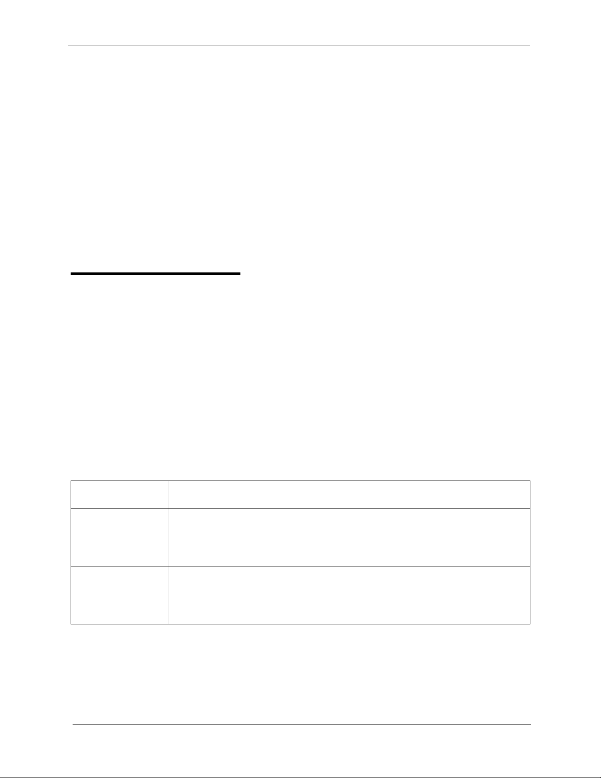
Toll Restriction System Features
• FF1 (System): SMDR Start Timer for CO Calls
• FF1 (System): SMDR Printing Mode 1: Outbound and Inbound
• FF1 (System): SMDR Printing Mode 2: Long Distance and Local Calls
• FF1 (System): SMDR Printing Mode 3: Header Title
• FF3 (Extension) Station Message Detail Recorder (SMDR) Report
Hardware Requirements
• A printer or external call accounting system is required to output SMDR
data.
Toll Restriction
(CPC-S and CPC-M)
Description
Access levels, including the prohibition of long distance calls or after-hours
calls, can be assigned to specific extensions or CO lines using the Toll
Restriction feature. This minimizes non-business related calls and reduces
phone bills by only allowing long distance calls over designated lines.
The following access levels are available:
Table 1-2. Toll Restriction Types
Toll Restriction
Type
0 Restriction of outbound dialing (except 911)
1 Full restriction of outbound dialing (except 911).
Characteristics
Inbound ringing trunks can be answered by or transferred to Type 0 extensions.
Intercom calls are allowed.
Cannot perform Group Call Pickup.
Inbound ringing on all trunks.
Intercom calls are allowed.
Group call pickup is allowed.
1-38 DBS 824-3.0/3.2-700 Revised A pril 2000
Page 56

System Features Toll Restriction
2 Local calls allowed
1-800 calls allowed
Inbound trunk calls can be answered and transferred from a Type 2 phone.
Full restriction of international calls.
Full restriction of operator calls.
Speed dial number selectable restriction.
N11 code selectable restriction except 911.
Restriction of up to 50 seven-digit numbers.
Inter-digit timing is set to 6 seconds.
3 1-800 calls allowed.
Full restriction of operator calls.
Selectable restriction of international calls.
Selectable restriction of N11 codes (211-811).
Speed dial number selectable restriction.
Restriction of up to 50 seven-digit numbers.
Trunk calls can be answered and transferred.
Defaulted to full restriction of area-code dialing (see Notes).
Defaulted to full restriction of office-code dialing (see Notes).
Inter-digit timing is set to 6 seconds.
4 Identical to Type 3, except that office-code dialing is allowed by default; type 4 also
allows Operator Calls (Type 3 does not allow Operator Calls) (See Notes).
5 Programmable TRS Type; defaulted to no restrictions (see Notes).
6 Programmable TRS Type; defaulted to no restrictions (see Notes).
7 No restriction of outbound dialing.
Notes:
For TRS types 3-6, operator calls are allowed if FF7 1# 1# is set to “on.” The office code tables are used to restrict
all 0 plus dialing; the next two digits will also be analyzed.
For TRS types 3-6, area code and office code restrictions can be changed using “Area Code Table For TRS Types
3-6‚” “Office Code Table For TRS Types 3-6‚” “Special Area Code Table For TRS Types 3-6‚” and “Special
Office Code Table For TRS Types 3-6‚” explained in Chapter 8 of Programming (Section 400).
For TRS types 3-6, area and office code restrictions can be further managed using “Special Area Code Table For
TRS Types 3-6” and “Special Office Code Table For TRS Types 3-6” found in Chapter 8 of Programming (Sec-
tion 400). Four area codes can be associated with special area code tables 1-4 (one area code per table). Within
each of these tables, the entire range of valid office codes can be individually allowed or restricted. Thus, the Special Area and Office Codes work together to provide specific toll restrictions.
The following calling restrictions are also available:
• Station Lockout Key Code Restriction
A key code must be entered before calling out when the Station Lockout
feature is activated.
• Account Code Restriction
An Account Code must be entered before calling out.
Revised April 2000 DBS 824-3.0/3.2-700 1-39
Page 57

Trunk Groups System Features
• Forced LCR Restriction
The LCR feature controls outside calls.
Related Programming
• FF1 (System): Override Toll Restrictions with SSD Numbers
• FF3 (Extension) Extension Lockout Code
• FF7 (Toll Restriction): Toll Restriction Settings (all)
Considerations
• The dialing restrictions included in this feature help prevent unauthorized
outgoing calls. It is possible, however, to program your system to allow
System Speed Dialing to override Toll Restrictions.
Trunk Groups
(CPC-S and CPC-M)
Description
Trunks can be placed in trunk groups. When a trunk group is accessed, the
DBS 824 automatically selects an open trunk from the group.
Operation
To access a trunk group, do one of the following:
• Dial a trunk group access code before dialing the telephone number. Tr unk
group access codes are 9, 81, 82, 83, 84, 85, and 86.
• Press an FF key that is assigned as a pooled trunk key.
Related Programming
• FF2 (Trunks): Pooled Trunk Access for Group “9”
• FF2 (Trunks): Pooled Trunk Access for Groups “81-86”
Considerations
1-40 DBS 824-3.0/3.2-700 Revised A pril 2000
Page 58

System Features Trunk Name Assignment
• Trunks can appear in more than one trunk group.
• If Least Cost Routing is enabled, the trunk group “9” automatically
accesses the LCR features.
Trunk Name Assignment
(CPC-S and CPC-M)
Description
You can display a name, number, or message of up to six characters on the
LCD in place of your CO trunk line number. The name will appear when a
CO call is ringing or connected.
For example, you can assign specific CO lines to different individuals or
departments. Then, when an extension rings, the individual’s name or the
department’s name will appear on the display, immediately identifying the
person for whom the call is intended.
While you are speaking on the extension, “CO TALK XXXXXX” will appear
on the LCD. (XXXXXX represents the six characters of the Trunk Name.)
While the extension is ringing, “INCOMING XXXXXX” will appear. While
the extension is ringing and you are speaking on the extension at the same
time, “INCOMING XXXXXX” will appear on the second line of the display.
Related Programming
• FF6 (Name and Message): Trunk Name Assignment
Considerations
• Trunk names can be assigned with a DSS or an attendant phone.
• If a text name is assigned to a CO trunk, the trunk number does not appear
on the display.
Revised April 2000 DBS 824-3.0/3.2-700 1-41
Page 59

Trunk Queuing System Features
Trunk Queuing
(CPC-S and CPC-M)
Description
If all outside lines in a Trunk Group are busy , the system can call you when a
line becomes free. When the Trunk Callback alert tone rings, simply pick up
the handset and dial the telephone number .
Operation
To set Trunk Queuing:
1. Press the
2. Press the CO line key or dial a trunk access code.
The phone issues busy tone.
3. Press “2.”
“In CO Queuing” appears on the display.
4. Press the
5. Wait for the Trunk Callback alert tone.
To respond to the Trunk Callback alert tone:
Pick up the handset.
• The outside line is automatically accessed.
• The phone issues dial tone.
• “CO T ALK #XX” (where “XX” is the line number) appears on the display .
ON/OFF
ON/OFF
key.
key.
Related Programming
• FF1 (System): Extension Class of Service Setting
• FF3 (Extension): Extension Class of Service Assignment
1-42 DBS 824-3.0/3.2-700 Revised A pril 2000
Page 60

System Features Universal Night Answer
Considerations
• Response to the Trunk Callback alert tone must be within sixteen seconds
or Trunk Queuing will be canceled.
• If a call arrives from an outside line while the Trunk Queuing feature is
activated, Trunk Queuing will be suspended for the duration of the
incoming call.
• If you are engaged in another call on a different line for more than twenty
minutes after the desired outside line becomes available, that outside line’s
assignment to you will be canceled.
• The Trunk Queuing feature may also be used if you hear a busy tone when
trying to make a call using the Pooled Trunk Access feature.
• Trunk Queuing can be used by SLTs.
Universal Night Answer
(CPC-S and CPC-M)
Description
Operation
To answer a UNA call:
During night mode, Universal Night Answer (UNA) incoming calls can be
indicated on an external speaker system.With the CPC-M, calls can
alternatively be indicated on an external ringer, such as a night bell.
Universal Night Answer calls can be picked up from any extension, provided
the extension’s Class of Service allows UNA answer.
1. Pick up the handset.
The phone issues intercom dial tone.
2. Dial “78.”
“CO TALK #XX” appears on the display (where “XX” = the trunk
number).
Revised April 2000 DBS 824-3.0/3.2-700 1-43
Page 61

Voice Mail Ringing System Features
Related Programming
• FF1 (System): Extension Class of Service Setting
• FF1 (System): Ring Patterns for UNA Terminals (M, C, & B)
• FF3 (Extension): Extension Class of Service Assignment
• FF4 (Ringing and Hunt Groups): CO Day Ring Assignment
• FF4 (Ringing and Hunt Groups): CO Night Ring Assignment
Hardware Requirements
• An external ringing device is not provided with the DBS 824. It can be
purchased separately from an electronics dealer.
• An external amplifier and speakers are not provided with the DBS 824;
they must be purchased separately.
Considerations
• Extension port 17 (CPC-S) or port 25 (CPC-M) is used to assign ringing to
an external UNA interface.
Voice Mail Ringing
(CPC-S and CPC-M)
Description
The Voice Mail Ringing feature allows calls from a DBS 824 Automated
Attendant or from an ACD port to ring an extension with the same ring tone
as a CO trunk. The ring pattern is selected in the Extension Distinctive
Ringing program. If a distinctive ringing pattern is not specified, the ringing
pattern will be two seconds on/two seconds off.
Related Programming
• FF3 (Extension): Extension Ring Pattern
1-44 DBS 824-3.0/3.2-700 Revised A pril 2000
Page 62

System Features VAU
VAU
(CPC-S and CPC-M)
Description
The Voice Announce Unit (VAU) is a digital answering device that can be
connected to the DBS 824. It provides for the recording and playback of up to
two voice messages, along with the ability to transfer incoming calls.
When a call reaches the VAU, it plays a prerecorded voice message. The
caller is then allowed to dial a number or is automatically transferred to a
predetermined extension.
The VAU is often used to back up operators or hunt groups. Callers
overflowing from either of these positions hear a message and can then dial a
number or wait to be transferred back to the operator or hunt group.
The VAU can be used to provide a variety of other services to callers, such as
a menu of dialing options or transfer to an answering machine.
VAU Port Assignment
(CPC-S and CPC-M)
Operation
A digital port can be assigned as a VAU through system programming.
The following call types are routed to the first VAU message:
•DISA calls
•Transferred trunk calls
•Transferred intercom calls.
All recalls are routed to the second message.
Programming
• FF3 (Extension): VAU Port Assignment
• FF3 (Extension): VAU Hunting Priority
Revised April 2000 DBS 824-3.0/3.2-700 1-45
Page 63

Walking TRS Class of Service System Features
Walking TRS Class of Service
(CPC-S and CPC-M)
Description
Walking TRS Class of Service allows an extension user to “carry” his or her
toll restrictions to another phone.
Before the Walking TRS Class of Service feature can be used, a Walking
Class of Service code must be entered for each extension that wants to use
dialing privileges at another extension.
To enter a Walking Class of Service code:
1. Pick up the handset.
The phone issues intercom dial tone.
Operation
2. Dial “#12.”
3. Enter the four-digit Walking Class of Service code (0001-9999).
To enter a Walking Class of Service code:
1. Pick up the handset.
The phone issues intercom dial tone.
2. Dial “#12.”
3. Enter the four-digit Walking Class of Service code (0001-9999).
4. Press “#.”
5. Replace the handset.
To use a Walking Class of Service code:
1. Pick up the handset of an extension other than your own.
The phone issues intercom dial tone.
2. Dial “#13.”
1-46 DBS 824-3.0/3.2-700 Revised A pril 2000
Page 64

System Features Walking TRS Class of Service
3. Enter your extension number.
4. Enter your Walking Class of Service code.
5. Press “#.”
6. Enter a trunk access code (88XX, 9, 81-86).
The phone issues outside dial tone.
7. Dial the telephone number.
The Walking Class of Service remains in effect until you replace the
handset.
To clear a Walking Class of Service code:
1. Pick up the handset.
The phone issues intercom dial tone.
2. Dial “#12.”
3. Enter the original Walking Class of Service code.
4. Press “#.”
5. Replace the handset.
T o confirm a W alk ing Class of Service code (Attendant Phone only):
1. Pick up the handset.
The phone issues intercom dial tone.
2. Press the
3. Dial “#12.”
4. Enter the extension number.
The Walking Class of Service code for that extension appears on the
display.
CONF
key.
Considerations
• Walking Class of Service can be used by KTELs, DSLTs, and SLTs.
• A Walking Class of Service code can be used on more than one extension.
Revised April 2000 DBS 824-3.0/3.2-700 1-47
Page 65

Walking TRS Class of Service System Features
• If an extension is locked out, the Walking Class of Service feature will
override the lockout.
• LCR and TRS dialing privileges follow the Walking Class of Service.
1-48 DBS 824-3.0/3.2-700 Revised A pril 2000
Page 66

Chapter 2. Attendant Features
This chapter describes features that are available to an attendant phone.
In addition to functioning as a central answering point, an attendant phone
also has special capabilities for monitoring and programming other phones.
This chapter covers the following topics:
Topic Page
Attendant Assignment of Speed Dialing 2-3
Attendant Busy Override 2-4
Attendant Call Park 2-5
Attendant Control of Absence Messages, 2-6
Attendant-Controlled Text Assignment 2-7
Attendant Groups 2-9
Dial Tone Disable 2-10
DSS/72 2-11
Headset Operation 2-13
Key Bank Hold 2-14
One-Touch VM Transfer 2-14
Station Lockout Code Assignment 2-17
System Time and Date Control 2-18
Traffic Measurement 2-20
Walking COS Confirmation 2-22
Revised April 2000 DBS 824-3.0/3.2-700 2-1
Page 67

2-2 DBS 824-3.0/3.2-700 R evised April 2000
Page 68

Attendant Features Attendant Assignment of Speed Dialing
Attendant Assignment of Speed Dialing
(CPC-S and CPC-M)
Description
The attendant can assign system speed dialing numbers. System speed dialing
numbers are shared by all DBS 824 extensions.
Operation
1. Press the
• The phone issues intercom dial tone.
• The
2. Press the
“F” appears on the display.
3. Press
“FA” appears on the display.
4. Enter the Speed Dial code (00-89 or 000-199).
“Enter SSD XX” appears on the display (where “XX” is the System
Speed Dial code).
5. Dial the telephone number to be stored.
The number appears on the display.
6. Press the
ON/OFF
ON/OFF
PROG
AUTO
.
HOLD
key.
LED lights.
key.
key.
“SSD XX” (where “XX” is the Speed Dial code) and the stored telephone
number appear on the display.
7. Repeat steps 2-6 to store additional numbers.
Considerations
• Storing a new number erases any previously stored data.
• To delete a System Speed Dial number, perform the programming steps,
but do not enter a number before pressing
Revised April 2000 DBS 824-3.0/3.2-700 2-3
HOLD
.
Page 69

Attendant Busy Override Attendant Features
• Names for System Speed Dialing can also be stored using a DSS console
connected to the attendant phone.
Attendant Busy Override
(CPC-S and CPC-M)
Description
The Attendant Busy Override feature allows the attendant to break in on an
Intercom Call or a CO Call that is already in progress.
Attendant Busy Override can break into any extension, even if the extension
has “Busy Overridden” turned off. (The extension feature “Busy Override”
cannot break into an extension that has “Busy Overridden” turned off.)
System programming determines whether the override is preceded by an alert
tone. By default, Attendant Override does not sound an alert tone.
Operation
To override a busy extension:
Press “4.”
“CONF XXX YYY” (where “XXX” and “YYY” are the extension numbers)
appears on the display.
Related Programming
• FF1 (System): Attendant Override
• FF1 (System): Alert Tone for Busy Override & OHVA
Considerations
• Replace the handset to exit the three-party conference call.
• The alert tone can be turned on or off through system programming.
2-4 DBS 824-3.0/3.2-700 Revised April 2000
Page 70

Attendant Features Attendant Call Park
Attendant Call Park
(CPC-S and CPC-M)
Description
Using the Attendant Call Park feature, the Attendant may park an outside call
until the called party can be found. The attendant can then use the Paging
feature to inform the called party of the call’s Park Number. The parked call
can then be retrieved from any extension by dialing the Park Number.
The attendant phone is equipped with ten outside line Park Numbers (00-09).
Programming a Call Park key into an FF key on a telephone or a DSS console
makes one-touch Call Park possible.
Operation
To park an outside call:
1. Press the
• The outside call is placed on hold.
• “CO HOLD #XX” (where “XX” is the trunk number) appears on the
display.
2. Dial “75.”
3. Enter desired Park Number (00-09).
“PARK HOLD 01” appears on the display if you selected Park Number
01.
To release a parked call (after receiving the Park Number from the
Attendant):
1. Pick up the handset.
The phone issues intercom dial tone.
HOLD
key.
2. Dial “76.”
3. Enter the Park Number assigned to the call.
“PARK PICK XX” (where “XX” is the park number) appears, and then
“CO TALK #XX” (where “XX” is the trunk number of the call) appears.
Revised April 2000 DBS 824-3.0/3.2-700 2-5
Page 71

Attendant Control of Absence Messages, Attendant Features
Related Programming
• FF1 (System): Attendant Park Hold Recall Timer
Considerations
• An FF key assigned to Call Park indicates when a call is parked.
• If a parked call is not answered before the Attendant Park Hold Recall
Timer expires, the parked call recalls to the attendant.
Attendant Control of Absence Messages,
Call Forwarding, and DND
(CPC-S and CPC-M)
Description
Operation
An attendant phone can cancel the Absence Message, Call Forwarding, and
Do-Not-Disturb (DND) features activated on any extension.
To cancel an Absence Message, Call Forwarding, or DND:
1. Press the
• The phone issues intercom dial tone.
• The
2. Press the
3. Dial the extension number.
4. Press “*.”
5. Press the
ON/OFF
ON/OFF
CONF
ON/OFF
key.
LED lights.
key.
key.
ON/OFF
The
LED goes off.
Considerations
2-6 DBS 824-3.0/3.2-700 Revised April 2000
Page 72

Attendant Features Attendant-Controlled Text Assignment
• On DSS consoles equipped with DSS keys, the indicator for an extension
that has Absence Message, Call Forwarding, or DND activated lights
green. This indicator goes off when the feature is canceled. The indicator
does not light for Permanent Call Forwarding.
Attendant-Controlled Text Assignment
(CPC-S and CPC-M)
Description
The attendant can assign text to extensions, system speed dial numbers, and
Call Waiting/OHVA text replies without using a DSS/72 or entering the
programming mode.
Text is assigned through the dial pad on the attendant phone.
Operation
To assign names to extensions:
1. Pick up the receiver or press the
2. Press
3. Dial #2.
4. Enter the extension’s port number.
5. Press
6. Use the dialpad sequences shown in Table 2-1 on page 2-8 to enter letters
7. To store your entry, press
PROG
AUTO
and/or numbers.
FLASH
Press
CONF
Press
.
to backspace and erase the existing name.
after each letter.
to switch between numbers and letters.
HOLD.
ON/OFF
key.
To assign names to System Speed Dial numbers:
1. Pick up the receiver or press the
2. Press
Revised April 2000 DBS 824-3.0/3.2-700 2-7
PROG
.
ON/OFF
key.
Page 73

Attendant-Controlled Text Assignment Attendant Features
3. Dial #1
4. Press
AUTO
.
5. Dial the desired system speed dial number (00-89 or 000-199).
6. Press
AUTO
to backspace and erase the existing name.
7. Use the dialpad sequences shown in Table 2-1 to enter letters and/or
numbers.
FLASH
Press
CONF
Press
8. To store your entry, press
after each letter.
to switch between numbers and letters.
HOLD.
To assign text to Call Waiting/OHVA Text Replies):
1. Pick up the handset or press
2. Press
PROG
.
ON/OFF
.
3. Dial #5
4. Dial 1-5, depending on which text message you want to change.
5. Press
AUTO
to backspace and erase the existing name.
6. Use the dialpad sequences shown in Table 2-1 to enter letters and/or
numbers.
FLASH
Press
Press
CONF
after each letter.
to switch between numbers and letters.
7. To store your entry, press
Table 2-1. Key sequences for text assignment.
Key Number of Key Presses
Once T wice Three
1 Space Q Z Space q z
2ABCabc
3DEFdef
HOLD.
times
Four
times
Five
times
Six
times
4GHIghi
2-8 DBS 824-3.0/3.2-700 Revised April 2000
Page 74

Attendant Features Attendant Groups
Key Number of Key Presses
Once T wice Three
5JKLj kl
6MNOmno
7PRSprs
8TUVt uv
9 WXYwx y
0. : . : . :
**-?*-?
##/ !#/ !
Attendant Groups
(CPC-S and CPC-M)
Description
times
Four
times
Five
times
Six
times
The DBS 824 can accommodate up to four attendant positions. The first
attendant is fixed at port 1, extension 100. The other Attendants can be set to
any port or extension. When there is more than one attendant in a system, you
can create an Attendant Group with a pilot number of 0.
When all Multi-Line keys on the first attendant phone are busy, calls are
forwarded to the second, third, and fourth attendant phones, in that order.
Related Programming
• FF1 (System): Second Attendant Position
• FF1 (System): Third Attendant Position
• FF1 (System): Fourth Attendant Position
• FF1 (System): Attendant Transfer Extension
Considerations
• If all four phones are busy, calls are transferred to a preset destination,
which must be a real extension number. The forwarding destination cannot
be the pilot number of a hunt group.
Revised April 2000 DBS 824-3.0/3.2-700 2-9
Page 75

Dial Tone Disable Attendant Features
• The third and fourth attendants cannot have a DSS/72.
Dial “0” calls ring the first attendant, even if the first attendant has call
forwarding activated. However, if a call is unanswered, it does not skip to
the next attendant. The call continues to ring the first attendant until the
caller hangs up.
Dial Tone Disable
(CPC-S and CPC-M)
Description
The intercom dial tone can be turned off at an attendant phone. Dial tone is
turned off when a headset is used.
Operation
To disable the intercom dial tone:
1. Press the
• The phone issues intercom dial tone.
• The
2. Press “#50.”
3. Press the
The
To reactivate dial tone:
Repeat the preceding steps.
ON/OFF
ON/OFF
ON/OFF
ON/OFF
key.
LED lights.
key.
LED goes off.
2-10 DBS 824-3.0/3.2-700 R evised April 2000
Page 76
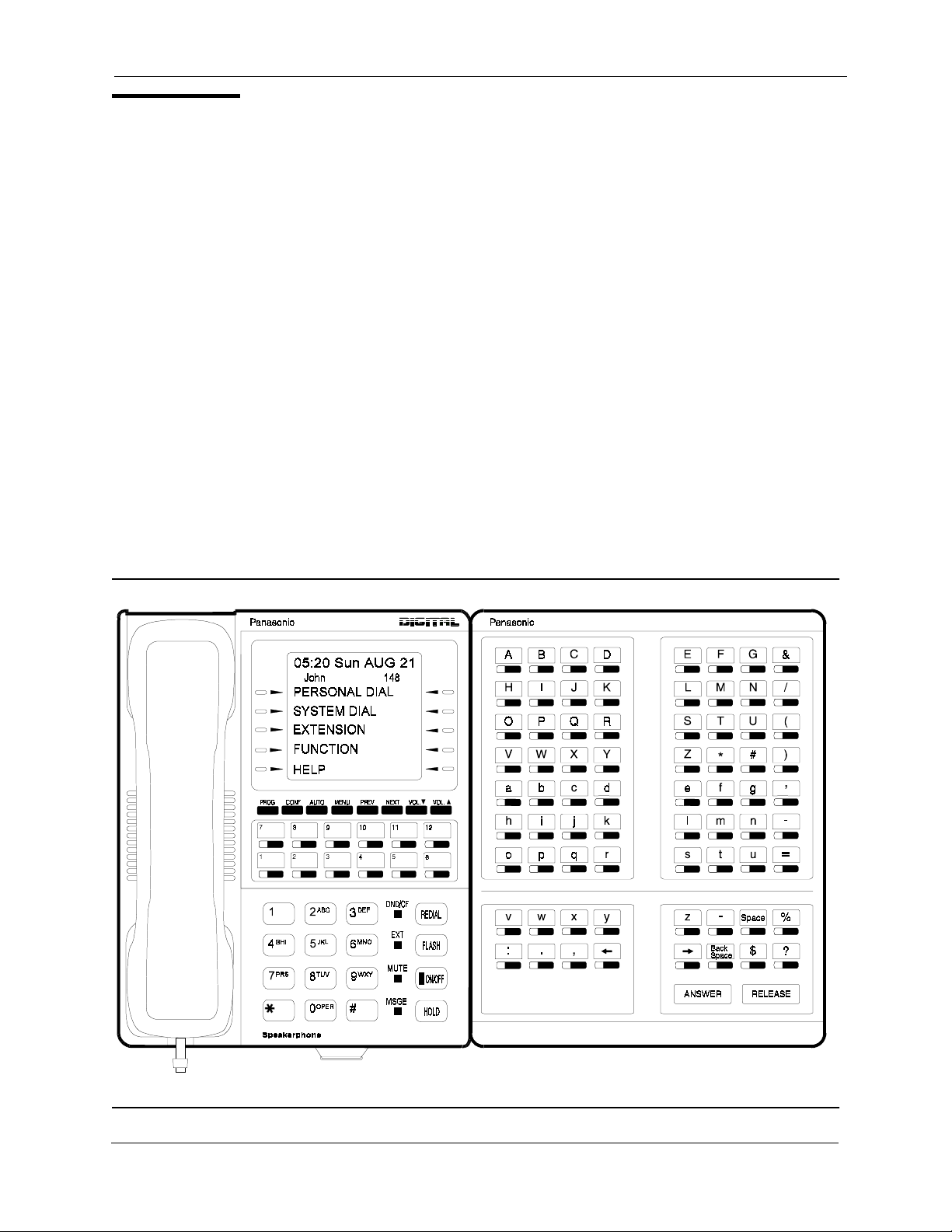
Attendant Features DSS/72
DSS/72
(CPC-S and CPC-M)
Description
The DSS/72 is a 72-key console that can be attached to the attendant phone.
The 72 keys of the DSS can be programmed as Direct Station Select (DSS)
keys for internal lines. In addition to providing direct station selection, the
DSS keys also provide busy lamp fields to assist the attendant in monitoring
the status of extensions.
The attendant can perform a simplified call transfer by pressing a DSS key
while connected to an outside line. The outside line is placed on hold and the
extension is dialed automatically.
When the attendant is placed in the programming mode, the DSS can be used
for inputting text names. Figure 2-1 shows which keys are pressed for text
input.
Figure 2-1. VB-43225 with a DSS/72
Revised April 2000 DBS 824-3.0/3.2-700 2-11
Page 77

DSS/72 Attendant Features
Related Programming
• FF3 (Extensions): Terminal Type
Hardware Requirements
Table 2-2. DSS/72 maximums
Attendant Position DSS/72 Assignments
Attendant 1
DSS/72
Attendant 2
DSS/72
Attendant 3 The DSS/72 cannot be assigned.
Attendant 4 The DSS/72 cannot be assigned.
• The DSS key LED informs the attendant of the status of assigned
extensions. The LED lights red when the extension is busy and green when
Absence Message, Call Waiting, or DND is activated.
• Pressing a DSS key while connected to an outside line places the line on
hold.
DSS/72
DSS/72
2-12 DBS 824-3.0/3.2-700 R evised April 2000
Page 78

Attendant Features Headset Operation
Headset Operation
(CPC-S and CPC-M)
Description
A headset can be connected to attendant or non-attendant phones. (Dial tone
is normally turned off when the headset is connected.)
Operation
To use a headset:
1. Connect a headset to the telephone.
2. Press the
3. Press “#51.”
ON/OFF
The
To stop using a headset:
Repeat the preceding steps.
Hardware Requirements
• Headsets are not provided with the DBS 824; they must be purchased
separately.
• Most commercially available headsets (with ECM mike transducers) can
be used.
ON/OFF
key.
LED remains lit.
Revised April 2000 DBS 824-3.0/3.2-700 2-13
Page 79

Key Bank Hold Attendant Features
Key Bank Hold
(CPC-S and CPC-M)
Description
Key bank hold allows a user on a trunk call to initiate another trunk call by
simply pressing an FF key for another trunk. When the user presses the FF
key, the first trunk call is automatically placed on system hold.
In addition, the attendant can use key bank hold with DSS/BLF keys to
provide one-touch call transfer to an extension. For example, if the attendant
phone has a DSS/BLF key assigned for extension 200, the attendant can
answer an incoming trunk call and then press the DSS/BLF key to
automatically transfer the call to 200.
If key bank hold is turned off, the user must press
second trunk or transferring a call.
Related Programming
• FF1 (System): Trunk Line Automatic Hold (Key Bank Hold)
One-Touch VM Tr ansfer
(CPC-S and CPC-M)
Operation
The VM key can also be used by attendants to easily transfer incoming callers
to an extension’s voice mailbox. When a user presses a voice mail key and
then presses a DSS/BLF key , the digit s programmed for the DSS/BLF key are
transmitted to the voice mail system.
HOLD
before accessing a
For example, if an attendant receives an incoming call for station 200 and the
attendant knows that station 200 is busy because the DSS/BLF key is lit red,
the attendant can press the VM key and then press the DSS/BLF key to
automatically transfer the caller to 200’s voice mailbox.
For a general description of the VM key as well as instructions on using the
key for personal message retrieval, see “One-Touch VM Access” on page 3-
65.
2-14 DBS 824-3.0/3.2-700 R evised April 2000
Page 80

Attendant Features One-Touch VM Transfer
Operation
Note:
for personal message retrieval or attendant transfer. See the following
“Operation” section for instructions.
To assign a voice mail key:
Note:
clear the FF assignments, then use the following procedures to assign the VM
key.
1. Press the
2. Press the
3. Press the FF key, DSS key, or One-Touch key.
The VM key is assigned differently, depending on whether it is used
You cannot program this feature if trunks are assigned to the key . First
ON/OFF
• The phone issues intercom dial tone.
• The
ON/OFF
PROG
key.
LED lights.
key.
4. Press the
5. Press the
6. Dial the voice mail extension number.
7. If the key is for personal message retrieval, enter a password (XXX or
AUTO 00-99) if desired. If the key is for attendant transfer to voice mail,
do not enter a password but include any special codes (* or #, for
example) if they are required by the voice mail system.
Note:
exceed six digits. If the VM number and the password total more than six
digits, assign the password to a personal or system speed dial number (0099 or 000-199, 900-939).
8. Press the
Attendant Transfer to Voice Mail
1. The attendant answers an incoming call.
CONF
AUTO
The length of the password and the VM extension number cannot
HOLD
key.
key.
key.
The incoming caller asks to be transferred to an extension number.
2. The attendant checks the DSS/BLF key for the extension. If the light is
red, the attendant presses the VM key followed by the DSS/BLF key.
Revised April 2000 DBS 824-3.0/3.2-700 2-15
Page 81

One-Touch VM Transfer Attendant F eatures
The incoming caller is transferred to the extension’s mailbox.
Related Programming
• FF5 (Keys): FF Key Assignment for Extensions
• FF5 (Keys): FF Key Assignments for DSS Consoles
Considerations
• Once an extension is connected to voice mail, pressing a DSS/BLF key
will transmit the extension number stored on the DSS/BLF key to the voice
mail system, regardless of what state the DSS/BLF key is in. In other
words, the extension number is transmitted whether the key is idle, ringing,
or busy.
Note:
is active; they do not flash red when an extension is ringing, or light green
when an extension is forwarded.
Note:
for transferring to voice mail, the personal VM key must be assigned to the
lowest-numbered FF key.
For example, if DSS keys 60 and 61 are assigned as VM keys, key 60
should be used for the attendant’s personal mailbox. If VM keys are
assigned to both the phone FF keys and the DSS keys, the lowest-numbered
FF key on the phone should be used for the attendant’s personal mailbox. If
the personal VM key is not assigned to the lowest-numbered key, it will not
flash to indicate VM messages.
DSS/BLF keys on the DSS/72 always light red when an extension
If an attendant wants one VM key for a personal mailbox and one
2-16 DBS 824-3.0/3.2-700 R evised April 2000
Page 82

Attendant Features Station Lockout Code Assignment
Station Lockout Code Assignment
(CPC-S and CPC-M)
Description
The Station Lockout feature allows users to dial a Station Lockout code to
restrict their phone from being used for outside calls.
Station Lockout codes can be assigned through the attendant phone.
Operation
To program a Station Lockout code:
1. Press the
• The phone issues intercom dial tone.
• The
2. Press the
3. Dial “#8.”
4. Dial the extension number.
5. Enter the desired key code (four digits).
6. Press the
“STORE XXXX” (where “XXXX” is the key code) appears on the
display.
7. Press the
The
ON/OFF
ON/OFF
CONF
HOLD
ON/OFF
ON/OFF
key.
LED lights.
key.
key.
key.
LED goes off.
Considerations
• A locked extension can be used for Intercom Calls.
• Station Lockout key codes can also be set through system programming.
Revised April 2000 DBS 824-3.0/3.2-700 2-17
Page 83

System Time and Date Control Attendant Features
System Time and Date Control
(CPC-S and CPC-M)
Description
The date and time displayed on all system extensions are set from an
attendant phone.
Operation
To set the date and time:
1. Press the
• The phone issues intercom dial tone.
• The current date and time are displayed on your LCD.
2. Press the
“F” appears on the display.
3. Dial “##.”
“Program Mode:” appears on the first line of the display; “MAIN
MODE” appears on the second line.
4. Press the FF1 key.
“SELECT SUB MODE” appears on the second line of the display.
5. Dial “1#.”
“1:DATE 2:TIME” appears.
6. Dial “1#.”
ON/OFF
PROG
key.
key.
“MONTH/DAY/YEAR” appears.
7. Enter six digits for the month, day, and year.
For example, to set the date to March 3, 1993, enter “030393.”
8. Press #.
“TIME SET MODE appears on the display.
2-18 DBS 824-3.0/3.2-700 R evised April 2000
Page 84

Attendant Features System Time and Date Control
9. Enter four digits for hours and minutes (24-hr. time).
For example, for 11:00 a.m., enter “1100.”
10. Press #.
11. Press the
The new date and time appear on the display.
To reset the minutes d isplay to “00:”
If the clock is five minutes slow or fast, you can re-synchronize the minutes
setting to “00,” provided the current minutes display is between “:55” and
“:05.”
1. Press the
• The phone issues intercom dial tone.
• The
2. Press the
“F” appears on the display.
3. Dial “#4.”
“Time Adjusted” appears on the display.
ON/OFF
ON/OFF
ON/OFF
PROG
key.
key.
LED lights.
key.
4. Press the
The
ON/OFF
ON/OFF
key.
LED goes off.
Considerations
• The month is entered in numeric form, but is displayed as the name of the
month.
• The day of the week is calculated automatically.
Revised April 2000 DBS 824-3.0/3.2-700 2-19
Page 85

Traffic Measurement Attendant Features
Traffic Measurement
(CPC-S and CPC-M)
Description
An attendant phone can track the number of outgoing and incoming calls for
each outside line number, as well as the number of times each System Speed
Dial number is used. This information can be used to evaluate trunk usage
and control costs.
To determine the number of outgoing calls made on an outside line:
1. Press the
• The phone issues intercom dial tone.
• The
2. Press the
“C” appears on the display.
3. Dial “#90,” then enter the number of the outside line you want to check.
If 1234 outgoing calls have been made on line 01, “OutGoing01 01234”
appears on the display.
Pressing the # key steps through the trunk numbers and system speed dial
numbers.
4. Press the
The
To check other usage rates:
ON/OFF
ON/OFF
CONF
ON/OFF
ON/OFF
key.
LED lights.
key.
key.
LED goes off.
Replace “#90” in Step 3 with one of the following codes:
2-20 DBS 824-3.0/3.2-700 R evised April 2000
Page 86

Attendant Features Traffic Measurement
Table 2-3. Traffic measurement options
Operation Code Display
Check the number of incoming calls to a specific trunk #91NN “Incoming NN”
Check the number of times a System Speed Dial number
was used:
Delete usage data: #93 “Clear All Inform”
Notes:
NN = CO line number (01-08)
SS = System Speed Dial number (00-89 or 000-199)
#92SS “SYS-SPD SS”
Considerations
• The Traffic Measurement feature can be accessed from any display phone.
• Usage data cannot be cleared item by item.
• All data is retained until it is deleted or until 65,536 entries are made (at
which point the figures are reset to zero).
• A backup battery protects memory contents in case of power failure.
Revised April 2000 DBS 824-3.0/3.2-700 2-21
Page 87

Attendant Features Walking COS Confirmation
Walking COS Confirmation
(CPC-S and CPC-M)
Description
The attendant can check the Walking Class of Service ID code of any
extension.
Operation
1. Press
2. Press
3. Dial #12 plus the extension number.
ON/OFF
CONF.
The Walking Class of Service ID code appears on the display.
.
Revised April 2000 DBS 824-3.0/3.2-700 2-22
Page 88

Chapter 3. Key Telephone Features
This chapter describes DBS 824 key telephone features. DBS 824 key
telephones are proprietary digital phones that provide feature access through
a combination of feature keys and access codes.
This chapter covers the following topics:
Topic Page
Key Phone 3-3
Absence Message 3-3
Auto Redial 3-6
Auto-Repeat Dial 3-7
Call Coverage Groups 3-8
Call Duration Display 3-10
Call Forwarding 3-10
Call Hold 3-14
Call Park 3-17
Call Pickup 3-19
Call Transfer 3-21
Call Waiting 3-25
Call Waiting/OHVA Text Reply 3-28
Camp-on 3-29
CO Line Key Trunk Access 3-30
Conference Calls 3-31
Delayed Ringing 3-33
Dial “0” for Attendant 3-34
Do-Not-Disturb (DND) 3-35
EM/24 Console 3-36
Flexible Function (FF) Keys 3-37
Handsfree Answerback 3-42
Handsfree Operation 3-43
Headset Operation 3-43
Intercom Calling 3-43
Last Number Redial 3-46
Line Appearances 3-47
Meet-Me Answer 3-54
Revised April 2000 DBS 824-3.0/3.2-700 3-1
Page 89

Topic Page
Message Waiting/Callback Request 3-55
Non-Appearing Outside Lines 3-58
Offhook Signaling 3-59
Offhook Voice Announce (OHVA) 3-60
One-Touch Keys 3-62
One-Touch VM Access 3-65
Onhook Dialing 3-67
Pooled Trunk Access 3-68
Prime Line Preference 3-70
Private Line 3-71
Reminder Call 3-72
Ringing Line Preference 3-73
Saved Number Redial 3-74
Speed Dialing 3-75
Station Lockout 3-81
Trunk-to-Trunk Transfer 3-82
3-2 DBS 824-3.0/3.2-700 Revised Apri l 2000
Page 90

Key Telephone Features Key Phone
Key Phone
As an example of a key phone, 3-1 illustrates the DBS 824 key phone model
VB-43225. The VB-43225 provides a large display that includes one-touch
access to speed dial numbers, telephone features, and help screens.
Please refer to “Appendix A: 2.0 Feature Update” for additional information
on VB-44225 Large Display Key Telephone features.
Figure 3-1. VB-43225 key phone
Absence Message
(CPC-S and CPC-M)
Description
Extension users can leave text messages on their phones when they are away.
Revised April 2000 DBS 824-3.0/3.2-700 3-3
Page 91

Absence Message Key Telephone Features
When the unattended extension is dialed, the text message displays on the
caller’s phone.
Any one of the following messages can be selected. Messages 5 to 9 can be
changed through system programming.
Table 3-1. Absence Messages
Operation
Message
No.
0 In Meeting
1 At Lunch
2 Out of Office
3 Vacation
4 Another Office
5 User Defined
6 User Defined
7 User Defined
8 User Defined
9 User Defined
To set an Absence Message
Message Text
1. Press the
• The phone issues intercom dial tone.
• The
2. Dial “71.”
“Enter Msg Code” appears on the display.
3. Enter a message code between 0 and 9 (See Table 3-1).
“Enter Parameter” appears on the display.
4. Enter the time you will return (optional). See Table 3-2 for examples.
5. Press the
• The
3-4 DBS 824-3.0 /3.2-700 Revised April 2000
ON/OFF
ON/OFF
ON/OFF
DND/CF
key.
LED lights.
key.
LED lights.
Page 92

Key Telephone Features Absence Message
• “At Lunch” appears on the display if you selected message code 1.
To cancel an Absence Message
1. Press the
• The phone issues intercom dial tone.
• The
2. Dial “71.”
“Enter Msg Code” appears on the display.
3. Press the
• The
• The
Related Programming
• FF1 (System) Extension Class of Service Setting
• FF3 (Extension) Extension Class of Service Assignment
ON/OFF
ON/OFF
DND/CF
display.
ON/OFF
LED lights.
ON/OFF
LED goes off.
LED goes off, and the message disappears from the
key.
key.
• FF6 (Names and Messages): Absence Messages
Considerations
• Calling parties without a display get a busy signal, rather than the Absence
Message.
• If a message code number that has not been programmed is selected,
“Absence,” followed by the code number, appears on the display.
• Absence Message return times can be input as shown in the following
table:
Table 3-2. Example Return Times for Absence Messages
Input Display
No input Return
9 Return 9:00
11 Return 11:00
Revised April 2000 DBS 824-3.0/3.2-700 3-5
Page 93

Auto Redial Key Telephone Features
615 Return 6:15
1035 Return 10:35
Four-digit numbers can also be input (0000-9999 = Hours & Minutes or
Month & Date).
• When an Absence Message is set on a DID extension, incoming DID calls
are routed according to the ringing assignment programmed for the
incoming trunk.
• DND and Absence Messages cancel Call Forwarding.
Calls to an extension with DND or Absence Message turned on are treated
differently, depending on whether they are trunk or intercom calls:
Intercom calls receive busy tone; trunk calls are routed to the extension
defined in permanent call forwarding.
The following types of incoming trunk calls follow permanent call forward
settings:
- Direct trunk calls
- Transferred trunk calls.
• Callback to an incoming CO call on a Private Line is available if the
Absence Message feature is activated.
Auto Redial
(CPC-S and CPC-M)
Description
If the Redial key is pressed when the extension is idle or receiving dial tone,
the last intercom or outside number is automatically redialed.
Related Programming
• FF3 (System): Auto-Redial on Extensions
• FF1 (System): Extension Class of Service Setting
• FF3 (Extension): Extension Class of Service Assignment
3-6 DBS 824-3.0 /3.2-700 Revised April 2000
Page 94

Key Telephone Features Auto-Repeat Dial
Auto-Repeat Dial
(CPC-S and CPC-M)
Description
When a called outside party is busy, pressing the REDIAL key while hearing
busy tone automatically redials the number. The system will keep redialing
the number until the called party answers, you hang up or the Auto-Repeat
Dialing Count is reached.
Related Programming
• FF1 (System): Auto-Repeat Dialing Count
• FF1 (System): Wait Timer for Auto-Repeat Dialing
• FF1 (System): Busy Tone Detection Timer
• FF1 (System): Dial Tone Detection Timer
• FF2 (Trunk): CO Busy Tone Detection
Busy Override
(CPC-S and CPC-M)
Description
Extensions in the same Paging Group (1-7) can break into one another’s
outside calls or intercom calls to relay urgent information or to create threeparty conference calls.
Operation
1. Pick up the handset.
The phone issues intercom dial tone.
2. Dial the extension number.
3. When you hear busy tone, dial “4.”
Revised April 2000 DBS 824-3.0/3.2-700 3-7
Page 95

Call Coverage Groups Key Telephone Features
• An alert tone sounds to both phones (system programming required).
• The
Related Programming
• FF1 (System): Alert Tone for Busy Override and OHVA
• FF1 (System): Extension Class of Service Setting
• FF3 (Extension): Extension Class of Service Assignment
• FF3 (Extension): Busy Override Send
• FF3 (Extension): Busy Override Receive
• FF3 (Extension): Extension Page Group
• FF3 (Extension): Call Waiting
Considerations
• You cannot break in on three-party conference calls.
EXT
LED lights.
• Attendants can be prevented from using busy override.
• The default for the override alert tone is “off.” If the override alert tone is
enabled, the tone will be sent to both parties when a call is overridden.
• “Overridden” does not appear on the display of an extension that has been
broken into.
• Call Waiting must be activated for Busy Override to operate on hunt
groups calls.
Call Coverage Groups
(CPC-S and CPC-M)
Description
Call coverage is designed for office workers who almost always want their
unanswered calls to be routed to the same secretary or secretaries.
Up to two extensions can be designated as covering phones (secretary).
3-8 DBS 824-3.0 /3.2-700 Revised April 2000
Page 96

Key Telephone Features Call Coverage Groups
For example, if an outside call on line 1 is sent to extension 135, but
extension 135 does not answer, the call will ring once when the call first
comes in at the covering phone and “TRK #01> 135” will appear on the
covering phone’s display.
If two extensions are designated as covering phones and the first in DND, the
second will receive the call.
Call coverage assignments are controlled through system programming,
rather than from individual extensions.
For extension-controlled routing of unanswered calls, see “Call Forwarding”
on page 3-10.
Related Programming
• FF3 (Extension): Offhook Signal
• FF4 (Ringing and Hunt Groups): Call Coverage Group Member Table
Considerations
• Up to four Call Coverage Groups can be programmed into your system. A
Call Coverage Group can have up to two covering phones and up to six
extensions.
• A member of one Call Coverage Group cannot belong to another Call
Coverage Group or to a Hunting Group.
• A single-line telephone (SLT) can be a member of a coverage group, but it
cannot be a covering phone.
• Calls to an extension in DND do not cover.
• Calls to an extension with Call Forwarding activated do not cover.
• If the Call Forwarding feature or the Absence Message feature is activated
for covering phone No. 1, covering phone No. 2 will “cover” the other
extensions in the group.
• Voice intercom calls do not activate call coverage. Only tone intercom
calls can activate call coverage.
Revised April 2000 DBS 824-3.0/3.2-700 3-9
Page 97

Call Duration Display Key Telephone Features
Call Duration Display
(CPC-S and CPC-M)
Description
The length of a conversation on a CO line usually appears on display phones.
The duration display shows the number of minutes and seconds the call has
lasted.
The display does not begin right away; it begins either 5, 16 or 30 seconds
after the call begins, depending on how the DBS 824 is programmed.
Related Programming
• FF1 (System): Call Duration Display
• FF1 (System): Call Duration Timer
• FF1 (System): SMDR Start Timer for CO Calls
Call Forwarding
CPC-S and CPC-M)
Call Forwarding allows users to send their calls to another extension, to an
outside line, or to voice mail. The following table shows the call forwarding
features available.
Table 3-3. DBS 824 Call Forwarding features
Feature
Call Forwarding--All Calls
Call Forwarding--No Answer
Call Forwarding--Busy
Call Forwarding--Busy/No Answer
Permanent Call Forwarding
Descriptions
Call Forwarding--All Calls
activated, all incoming calls to an extension are immediately forwarded.
3-10 DBS 824-3.0/3.2-700 Revised A pril 2000
. When the Call Forwarding- -Al l Calls f eatur e is
Page 98

Key Telephone Features Call Forwarding
Call Forwarding--No Answer.
activated, an unanswered call will ring until the Call Forward No Answer
timer expires. When the timer expires, the unanswered call is forwarded.
Call Forwarding--Busy.
incoming calls to a busy extension will be forwarded.
Call Forwarding--Busy/No Answer.
Answer feature is activated, all incoming calls to an extension that is busy or
does not answer will be forwarded.
Permanent Call Forwarding.
through system programming, rather than by the user. Permanent call
forwarding is normally used to forward calls to a voice mail system.
An extension user can invoke other forms of call forwarding (no answer,
busy, all calls) to temporarily override the permanent call forwarding
destination.
Permanent call forwarding can be used with busy, no answer, or busy/no
answer.
When Permanent Call Forwarding is assigned, the
not lit green, the DND/CF LED is off, and the second line of LCD displays do
not display the Call Forwarding assignment.
When Call Forwarding--Busy is activated, all
When Call Forwarding--No Answer is
When Call Forwarding--Busy/No
Permanent call forwarding is assigned
DSS
and/or
BLF
keys are
To activate Call Forwarding:
1. Press the
• The phone issues intercom dial tone.
•The
2. Dial “72.”
“ENTER FWD CODE” appears on the display.
3. Dial the appropriate call forwarding code.
ON/OFF
ON/OFF
key.
LED lights.
Call Forward
Type
All 0
Busy/no answer 1
Busy 2
No answer 4
Code
“ENTER FWD EXT#” appears on the display.
Revised April 2000 DBS 824-3.0/3.2-700 3-11
Page 99

Call Forwarding Key Telephone Features
4. If you are forwarding to an internal number, enter the number of the
extension you want to receive your calls. If you are forwarding to an
outside number, press
AUTO
plus the appropriate speed dial number.
Note:
programmed in personal or system speed dialing. Forwarding to an
outside number requires use of pooled access trunks (Dial 9, 81 - 86).
However, Dial 9 is not available when using Least Cost Routing mode.
5. Press the
• The
• “FWD-EXT 135” appears on the 2nd line of the display if extension
To cancel Call Forwarding
1. Press
2. Dial “72.”
3. Hang up.
Related Programming
To forward to an outside number, the number must be pre-
ON/OFF
DND/CF
135 is selected. If a name is assigned to the extension, the name appears
instead of the extension number.
ON/OFF
key.
LED lights.
.
Considerations
• FF1 (System): Call Forward No Answer Timer
• FF1 (System): Extension Class of Service Setting
• FF3 (Extension): Extension Class of Service Assignment
• FF3 (Extension): Permanent Call Forward Type
• FF3 (Extension): Permanent Call Forward Extension
• FF10 (Speed Dial): System Speed Dial Numbers
• FF10 (Speed Dial): Personal Speed Dial Numbers
• DND and Absence Messages cancel Call Forwarding.
Calls to an extension with DND or Absence Message turned on are treated
differently, depending on whether they are trunk or intercom calls:
Intercom calls receive busy tone; trunk calls are routed to the extension
3-12 DBS 824-3.0/3.2-700 Revised A pril 2000
Page 100

Key Telephone Features Call Forwarding
defined in permanent call forwarding.
The following types of incoming trunk calls follow permanent call forward
settings:
- Direct trunk calls
- Transferred trunk calls.
• Voice calls do not forward when Call Forwarding--No Answer is used.
• If several calls arrive at once at an extension set for Call Forwarding-No
Answer, all of the calls will be queued. (The timing for each call begins
with the ringing tone.)
• Extensions for which Call Forwarding to an external number has been set
cannot
- Be in the middle of an outside call when the feature is activated.
- Have a toll restriction setting that prohibits outside calls.
:
• To forward to an outside number, the number must be pre-programmed in
personal or system speed dialing. Forwarding to an outside number
requires use of pooled access trunks (Dial 9, 81 - 86). However, Dial 9 is
not available when using Least Cost Routing mode.
• Calls can be forwarded to a third-party voice mail using the “Call Forward
ID Code” described on page 1-12.
• In order for an extension to be permanently call forwarded to the pilot
number of a hunt group, the hunt group pilot number must be 244 or
above. For example, if extension 200 is assigned as the pilot number of a
hunt group, hunting will work properly when 200 is dialed. However,
permanent call forwarding will not work for any extension that is
permanently call forwarded to the hunt group pilot number.
Revised April 2000 DBS 824-3.0/3.2-700 3-13
 Loading...