

Page 1
USA
issued 6/2/98
Page 2
Warning:
This service information is designe d for experienced repa ir technicia ns only and
is not designed for use by the general public . It does not co ntain warnings or cautions to
advise non-technical individuals of potential dangers in attempting to service a product.
Products powered by electr icity should be serviced or repaired only by experienced
professional technicians. Any attempt to service or repair the product or products dealt
with in this service infor mation by anyone else could result in serious injur y or deat h.
FCC Warning
This equipment gene rates, uses, a nd can radiat e radio fre quency en ergy, and, if not in stalle d and use d properly, that
is, in strict accordance with the instruction manual, may cause interference to radio and televis ion reception. This
equipment has been tested and fou nd to comply with the limits for a Class A computing device in Subject J of Part
15 of FCC Rules, which are designed to provide reasona ble protection agains t such interference in a resi dential
insta llation. H o w ev er, there is no gu arantee that interfe r e n c e wi ll no t occur in a pa r ti cu lar instal lation. If th i s
equipment does cause interference by one or more of the following measures:
1. Reorient the receiving antenna,
2. Relocate the key s ervice unit and key telephones with respect to the receiver,
3. Move the equipment from the receiver,
4. Plug the key service unit into a differ ent outlet so that the equipment and receiver are on differe nt branch
circuits.
Battery Recycling Statement
The following stat ement applies if you purchas ed backup batteries with your s ystem.
THE PRODUCT YOU HAVE PURCHASED MAY CONTAIN SEALED LEAD ACID BATTERIES WHICH
ARE RECYCLABLE. AT THE END OF THEIR USEFUL LIFE, UNDER VARIOUS STATE AND LOCAL
LAWS, IT IS ILLEGAL TO DISPOSE OF THESE BATTERIES INTO YOUR MUNICIPLE WASTE STREAM.
PLEASE CALL 1-800-SAV-LEAD FOR INFORMATION ON HOW TO RECYCLE THESE BATTERIES.
The information contained in this do cum ent is subject to chan ge without notice and should not be construed as a
commitment by the Panasonic T elecommunication Sys tems Company (PTSC). PTSC reserves the right, without
notice, to make changes to equipment design as adva nces in engineering and manufacturing methods warran t.
The software and hardware described in this document may be used or copied only in ac cordance with the terms of
the license pertaining to said software or hardware.
Reproduction , publication, or dupli cation of this manual, or any pa rt thereof, in any manner, mechanically,
electronically, or photographically, is prohibited without permission of the Panasonic Telecommunication Systems
Company (P TSC).
Copyright 1998 by Panasonic Telecommunicati on S ystems Company (PTSC)
All rights reserved.
Page 3

Contents
About This Manual......................................................xv
Overview..................................................................................................................................................xv
Related Documents..................................................................................................................................xv
About Marks Used in This Manual........................................................................................................xvi
Chapter 1.Requirements........................................... 1-1
Mode l N u mb e r s ... ............ .. ........... ........... ............ ........... ........... ........... ... ........... ........... .................... ... . 1-1
FCC Re qu i r e m e nt s .. ........... ........... ........... ............ ........... ........... .. ............ ........... ........... ........... ............ . 1-1
Environmental Requirements ................................................................................................................1-4
Cleaning................................................................................................................................................. 1-5
Chapter 2.System Overview..................................... 2-1
Cabinet Description............................................................................................................................... 2-1
Cabinet Configurations .......................................................................................................................... 2-3
Circuit Cards.......................................................................................................................................... 2-4
Circuit Card Configuration ................................................................................................2-4
Card Descriptions ............................................................................................................... 2-5
Chapter 3.Cabinet Installation.................................. 3-1
Installation Loc ation........................... ............. ....................... ............. ....................... ........................... 3-1
Removing and Replacing Covers. ......................................................................................................... 3-2
Front Cover ........................................................................................................................ 3-3
Side cover ...........................................................................................................................3-4
Top Cover (Base Cabinet Only) ......................................................................................... 3-5
Cabinet Installation. ............................................................................................................................... 3-6
Grounding . ............................................................................................................................................. 3-8
Battery Backup (VB-44025).................................................................................................................. 3-9
-48 Volt Power Supply (VB-44022).......... .. ............. .................................. ............. ............................ 3-11
Card Installati on............. ....................... ............. .......... .. ........................ ....................... ....................... 3-13
576-13-300 DBS 576 (USA), issued 6/2/98 iii
Page 4

Chapter 4.Installing Additional Cabinets................ 4-1
Installing the Buil ding Block System....................... ....................... ............. ....................... ..................4-1
Installation Location ..........................................................................................................4-1
Installation .......................................................................................................................... 4-2
Building Block Method (floor -mounting) Installation (576- port example shown)............. ............. ..... 4-4
Building Block Method (wall- mounting) Installation (576-port example shown)............ ............. ....... 4-7
Installing Switch Boxes (VB-44023) ............................................................................... 4-11
Battery Backup (VB-44025)................................................................................................................ 4-19
-48 Volt Power Supply (VB-44022).......... .. ............. .................................. ............. ............................ 4-20
Connecting the Systems ................................................................................................... 4-22
Setting ID No. of Additional Cabinets ............................................................................. 4-27
Connecting DBS 576 and DBS 96 Systems........................................................................................ 4-28
Installation ........................................................................................................................ 4- 2 8
Card Installation ............................................................................................................... 4-29
Connecting the Systems ................................................................................................... 4-29
Card Installati on Position ............ ............. ....................... ............. ....................... ............. ................... 4-33
Chapter 5.Trunks and Extensions ........................... 5-1
Maintenance Switches........................................................................................................................... 5-1
Trunks.................................................................................................................................................... 5-3
Trunk MDF Interface Card ................................................................................................ 5-4
Loop-Start Trunks ..............................................................................................................5-6
Loop-Start/Ground Start Trunks ......................................................................................5-10
DID Trunks ...................................................................................................................... 5-14
E&M Tie Line Trunks ......................................................................................................5-17
T-Point ISDN Interface (TBRI) ....................................................................................... 5-19
T-Point ISDN Primary Rate Interface (PRI) ......... ....... .... .. .... .... .. .... .... .. .... .... .. .... .... .. .... .. 5- 22
T1 Interface.......................................................................................................................................... 5-25
Extensions............................................................................................................................................ 5-28
Extension MDF Interface Card ... .... ...... .... ...... .... ........... .... ...... .... ...... .... ...... .... ...... .... ...... 5- 29
Digital Extensions ............................................................................................................ 5-31
DBS 96 Digital Extensions .............................................................................................. 5-34
Analog extensions ............................................................................................................ 5-39
S-Point ISDN Interface (SBRI) ........................................................................................ 5-42
S-point ISDN Primary Rate Interface (PRI) .................................................................... 5-45
Key Phone Wall Mounting............ ....................... ............. ....................... ............. .............................. 5-48
Chapter 6.Peripheral Equipment.............................. 6-1
Music -O n -Hold (M O H )..... .. .. ............ ........... ........... ........... ............ .. ........... ........... ............ ......... .. .. ...... 6 -1
iv DBS 576 (USA), issued 6/2/98 576-13-300
Page 5

Background Music (BGM).................................................................................................................... 6-2
Paging.................................................................................................................................................... 6-4
PC Customization Tool.......................................................................................................................... 6-7
Call Logging Device........................ ....................... ............. .......... .. ........................ ............................ 6-10
MIS Rep o rt O u tp u t ... .. ........... ............ .. ........... ........... ............ ........... ........... ........... ... .......... . .. ........... .. 6-14
Application Interface (API)................................................................................................................. 6-16
Voice Recognition Adapto r.................... .................................. ............. ....................... ....................... 6-18
DSS...................................................................................................................................................... 6-20
EM24 ................................................................................................................................................... 6-21
TAPI Adaptor...................................................................................................................................... 6-22
Doorphone Adaptor.............. ....................... ............. ....................... ........................ ............................ 6-23
Power Failure Transfer........................................................................................................................ 6-26
Replacing the Backup Batter y of CPC card............................. ............. ....................... ....................... 6-29
Chapter 7.Specifications .......................................... 7-1
Index ...................................................Index-i
576-13-300 DBS 576 (USA), issued 6/2/98 v
Page 6

vi DBS 576 (USA), issued 6/2/98 576-13-300
Page 7

List of Tables
Table 1-1 DBS 576 model numbers......................................................................................1-1
Table 1-2 FCC information............................................................................................................... 1-1
Table 1-3 Interface information........................................................................................................ 1-2
Table 2-1 Unit card configuration.........................................................................................2-4
Table 2-2 Switch settings of CPU96 card......................................................................................... 2-6
Table 2-3 LED indication of CPC96 card............... .. ........................ ....................... ............. ............2-6
Table 2-4 Switch settings of CPC288 card.......................... ............. ....................... ............. ............2-8
Table 2-5 LED indications of CPC288 card ................. .................................. ............. ..................... 2-8
Table 2-6 Switch settings of CPC576 card.......................... ............. ....................... ............. .......... 2-10
Table 2-7 LED indications of CPC576 card ................. .................................. ............. ................... 2-10
Table 2-8 LED indications of CBL card......................................................................................... 2-13
Table 2-9 LED indications of CBLDBS card............................. ............. .................................. ..... 2-14
Table 2-10 LED indications of SYNC package................. ............. ............. .......... ............. ............. .2-18
Table 2-11 SCC card switch settings................................................................................................ 2 -20
Table 2-12 Maintenance switch (SW1) settings of LTRK/8 card..................................................... 2-22
Table 2-13 Caller ID switch (SW10-17) settings of LTRK/8 card.......... ............. ....................... ..... 2-22
Table 2-14 LED indications of LTRK/8 card............... ............. .................................. ..................... 2-22
Table 2-15 Ground Start/Loop Start jum per settings of LGTRK/8 card..... ....................... ............. .2-24
Table 2-16 Maintenance switch (SW4) settings of TBRI/4 card............................... ............. .......... 2-29
Table 2-17 Circuit select swit ch (SW1) set tings of TBRI/4 card ........ .. ............. .............................. 2-29
Table 2-18 LED indication of TBRI/4 card........... ....................... ............. .................................. ..... 2-29
Table 2-19 Maintenance switch (SW4) settings of PRI/23 card... .. ............. .......... ............. ............. .2-31
Table 2-20 Dip switch (SW1) settings of PRI/23 car d ................. ............. .................................. ..... 2-31
Table 2-21 Dip switch (SW2) settings of PRI/23 car d ................. ............. .................................. ..... 2-32
Table 2-22 LED indications of PRI/23 card ...... ............. .................................. ............. ................... 2-32
Table 2-23 Maintenance switch (SW3) settings of T1 card....................................... ............. .......... 2-34
Table 2-24 Dip switch (SW1) settings of T1 card ............................................................. ............... 2-34
Table 2-25 Dip switch (SW2) settings of T1 card ............................................................. ............... 2-34
Table 2-26 LED indications of T1 card .... ............. .................................. ............. ....................... ..... 2-34
Table 2-27 Settings of circuit selection switch of SBRI/4 card ........................................................ 2-38
Table 2-28 LED indications of SBRI/4 card...................... .. ............. .................................. ............. .2-38
Table 2-29 Mounting restriction of MFR/8 card........................ ....................... ............. ................... 2-39
Table 2-30 ACD Card Switch Settings....................... ............. .................................. ............. .......... 2-42
Table 2-31 ACD Card LED Indications...... .. .................................. ............. ....................... ............. .2-42
Table 2-32 VPU/4 Card LED Indication ............................... ............. ....................... ............. .......... 2-43
Table 2-33 VPU/8 Card LED Indication ............................... ............. ....................... ............. .......... 2-44
Table 2-34 VSSC Card Switch Settings.... ............. ....................... ............. ....................... ............. ... 2-46
Table 2-35 VSSC Card LED Indications............................... .................................. ............. ............2-46
Table 2-36 Maintenance switch (SW1) settings of API card............... ............. ............. ................... 2-47
Table 2-37 Internal diagnosis switch (SW2) settings of API card..................... .. ... .......................... 2-48
Table 2-38 Memory backup switch (SW3) settings of API card...... .. .......... .. ............. ..................... 2-48
Table 2-39 LED indications of API card.... ............. .................................. ....................... ............. ... 2-48
576-13-300 DBS 576 (USA), issued 6/2/98 vii
Page 8

Table 4-1 Relationship of Programming Address to DBS Card Postion............................4-32
Table 4-2 PRI/23 and T1 card limitations....................................................................................... 4-36
Table 5-1 Number of Trunk Interface Cards Required per Cabinet..................................... 5-4
Table 5-2 Maximum loop-start trunks per system............................................................................ 5-6
Table 5-3 Caller ID switch (SW10-17) settings of LTRK/8 card..... ....................... ............. ............5-7
Table 5-4 Loop Start Trunk Connections and Pinouts.............. ............. ............. ....................... ...... .5-9
Table 5-5 Maximum Loop-Start/Ground-Start Trunks Per Syst em....... ............. ....................... ..... 5-10
Table 5-6 Ground Start/Loop Start jumper settings of LGTRK/8 card.............. ....................... ..... 5-11
Table 5-7 Loop Start/Ground Trunk Connections and Pinouts............................. ............. ............5-13
Table 5-8 Maximum DID Trunks Per System................................................................................ 5-14
Table 5-9 DID Trunk Connections and Pinouts..............................................................................5-16
Table 5-10 Maximum E&M Tie Line Trunks Per System ........................ ....................... ............. ... 5-17
Table 5-11 Maximum Number of T-Point ISDN Interfaces Per System............ .............................. 5-19
Table 5-12 Line Selection Switch (SW1: SELECT) on TBRI/4 Card... ............. ....................... ....... 5-20
Table 5-13 Mode Settings of PRI/23 Card......... ............. .................................. ............. ................... 5-22
Table 5-14 Maximum Number of T-Point ISDN Primary Rate Interface Cards Per System...........5-23
Table 5-15 Switch Setting for SW2 on PRI/23 Card........... ............. ....................... ............. ............5-23
Table 5-16 Switch Setting for SW1 on PRI/23 Card........... ............. ....................... ............. ............5-24
Table 5-17 Mode Settings of T1 Card....... ............. .................................. ............. ....................... ..... 5-25
Table 5-18 Maximum Number of T1 Interface Cards Per System................................................... 5-25
Table 5-19 Switch Setting for SW2 on T1 Card......... ............. ....................... ............. ..................... 5-26
Table 5-20 Switch Setting for SW1 on T1 Card......... ............. ....................... ............. ..................... 5-27
Table 5-21 Number of Extension Interface Cards Require d per Cabinet........................ .... .. ..... .... .. 5-29
Table 5-22 Maximum cards and digital (and analog) extensions per system.......... ............. ............5-31
Table 5-23 Digital Extension Connections and Pinouts ...................... .. ........................ .................. .5-33
Table 5-24 Relationship of Programming Address to DBS Card Postion.............. ............. ............5-34
Table 5-25 DBS 96 Digital Extension Connections and Pinouts - Slots EC1, EC2, and EC3...... ...5-36
Table 5-26 DBS 96 Digital Extension Connections and Pinouts - Slots EC4, EC5, and EC6...... ...5-37
Table 5-27 DBS 96 Digital Extension Connections and Pinouts - Slots EC7, EC8, and EC/TRK. .5-38
Table 5-28 Maximum cards and analog (and digital) extensions per system.......... ............. ............5-39
Table 5-29 Analog Extension Connections and Pinouts.......................... ............. ........................... .5-41
Table 5-30 Maximum Number of S-point ISDN Interfaces Per System.......................................... 5-42
Table 5-31 Mode Settings of PRI/23 Card......... ............. .................................. ............. ................... 5-45
Table 5-32 Maximum Number of S-point ISDN Primary Rate Interface Cards Per Sys tem ..... .. .... 5-45
Table 5-33 Switch Setting for SW2-2 on PRI/23 Card.............................................. ............. .......... 5-46
Table 5-34 Switch Setting for SW1 on PRI/23 Card........... ............. ....................... ............. ............5-46
Table 6-1 Pinout of external connector (CN3) of SCC card.................................................6-4
Table 6-2 Settings of SW2 on SCC card................ .......... .. ............. .................................. ............. ... 6-5
Table 6-3 RS-232C port (CN5 and CN6) pinout of SCC card ......................................................... 6-7
Table 6-4 Positions of SW1 on SCC card ......................................................................................... 6-9
Table 6-5 ACD Card SW1 Settings.............. ....................... .................................. ............. ............6-14
Table 7-1 Input Power.......................................................... .......... .......... .......... .......... .........7-1
Table 7-2 Battery Backup Capacity.......................... ............. ....................... ........................ ............ 7-1
Table 7-3 Temperature and Humidity Requirements for System Operation
(excludes Built- In Voice Mail)7-1
Table 7-4 Temperature and Humidity Requirements for Built-in VM...... ....................... ............. ... 7-1
viii DBS 576 (USA), issued 6/2/98 576-13-300
Page 9

Table 7-5 Dimensions and Weight for Single-Cabinet Systems and Telephones ............................ 7-2
Table 7-6 Resource Maximums ........................................................................................................ 7-2
Table 7-7 Feature Related Capacities ............................................................................................... 7-3
Table 7-8 Hardware Maximums ....................................................................................................... 7-5
Table 7-9 Maximum Cabling Dista nces .............. ....................... ............. .................................. ....... 7-7
Table 7-10 Voice Path from KTELS to DBS 576........... .................................. ............. ..................... 7-7
Table 7-11 Data Communication Ports.................................. ............. ....................... .........................7-7
Table 7-12 Signaling to CO ................................................................................................................ 7-8
Table 7-13 Transmission Specific ations........................... ....................... ............. ....................... ....... 7-8
Table 7-14 DTMF Frequencies........................................................................................................... 7-8
576-13-300 DBS 576 (USA), issued 6/2/98 ix
Page 10

x DBS 576 (USA), issued 6/2/98 576-13-300
Page 11

List of Figures
Figure 2-1 The DBS 576 Base Cabinet ......................... ....................... ............. .............................. 2-1
Figure 2-2 System Connections....................................................................................................... 2-2
Figure 2-3 Example Cabinet Combinations..................................................................................... 2-3
Figure 2-4 CPC96 card .................................................................................................................... 2-5
Figure 2-5 CPC288 card .................................................................................................................. 2-7
Figure 2-6 CPC576 card .................................................................................................................. 2-9
Figure 2-7 TSW288 card ............................................................................................................... 2-11
Figure 2-8 TSW576 card ............................................................................................................... 2-12
Figure 2-9 CBL card ...................................................................................................................... 2-13
Figure 2-10 CBLDBS interface card ................. .. ..... .... .. ..... .... ..... .... ..... .. ..... .... .. ..... .... ..... .... ..... .. .... 2-14
Figure 2-11 CBLDBS MDF card..................................................................................................... 2-15
Figure 2-12 EXT MDF Interface card................... ..... .... ..... .. ..... .... .. ..... .... ..... .... ..... .. ..... .... .. ....... .. .. 2-16
Figure 2-13 TRK MDF In terface card.......... ..... .... ..... .... ..... .. ..... .... .. ..... .... ..... .... ..... .. ..... .... .. ....... .. .. 2-17
Figure 2-14 SYNC Package.............................................................................................................2-18
Figur e 2 -1 5 SCC card ........ ............ .. ........... ........... ............ ........... ........... ........... ... ........... ............... 2 -1 9
Figure 2-16 LTRK/8 card................................................................................................................ 2-21
Figure 2-17 CID card....................................................................................................................... 2-23
Figure 2-18 LGTRK/8 card............................................................................................................. 2-25
Figure 2-19 DIDTR 8 card............................................................................................................... 2-26
Figure 2-20 E&M/4 card.................................................................................................................. 2-27
Figure 2-21 TBRI/4 card..................................................................................................................2-28
Figur e 2 -2 2 PRI/ 2 3 card .. .. ... ........... ........... ........... ............ ........... ........... .. ............ ........... ............... 2-31
Figure 2-23 T1 card ......................................................................................................................... 2-33
Figure 2-24 DEC/8 card...................................................................................................................2-35
Figure 3-26 SBRI/4 card.... ..... .... ..... .. ..... .... .. ....... .. ..... .... ..... .. ..... .... ..... .... .. ..... .... ..... .. ....... .. ............. 2-37
Figure 3-27 MFR/8 card .................................................................................................................. 2-39
Figure 3-28 CONF card................................................................................................................... 2-40
Figur e 3 -2 9 ACD card ..... .. ............ ........... ........... ........... ............ ........... .. ........... ............ .................2-41
Figure 3-30 VPU/4 card................................................................................................................... 2-43
Figure 3-31 VPU/8 card................................................................................................................... 2-44
Figur e 3 -3 2 VSSC card ........... ........... ........... ... ........... ........... ........... ............ ........... ........... .. .. ......... 2-45
Figur e 3 -3 3 API ca r d .................. ............ ........... ........... .. ............ ........... ........... ........... .................... 2-47
Figure 3-1 Single base cabinet dimensions and maintenance area....... .. .................................. ....... 3-1
Figure 3-2 Removing and replacing front cover of base cabinet..................................................... 3-3
Figure 3-3 Removing and replacing side cover of base cabinet................ ............. ......................... 3-4
Figure 3-4 Removing and replacing top cover of Base Cabinet........... ............. ....................... ....... 3-5
Figure 3-5 Securing the cabinet to the floor (base cabinet shown) ................................................. 3-6
Figure 3-6 Cabinet plywood mounting backboard..........................................................................3-7
Figure 3-7 Wall-mounting Installation: Attaching the Wall-mounting Bracket....................... ....... 3-7
Figure 3-8 Wall-mounting Installation: Attaching the Wall-mounting of cabinet-1....................... 3-8
Figure 3-9 Grounding the Master Cabinet....................................................................................... 3-9
Figure 3-10 Installation of backup batteries (VB-44025)................................................................ 3-10
Figure 3-11 Installation of -48 Volt Power Supply (VB-44022)....................... ....................... ....... 3-12
576-13-300 DBS 576 (USA), issued 6/2/98 xi
Page 12

Figure 3-12 Typical Initial configuration for automatic starting of base cabinet system................ 3-13
Figure 3-13 Unit card instal lat ion in cabinet ................................................................................... 3-15
Figure 4-1 Building block system dimens ions and maintenance area............................................. 4-1
Figure 4-2 Example cabinet combinations using building block method ....................................... 4-3
Figure 4-3 Floor-Mounting Insta llation: Attaching the Wall-Mounting Bracket............................ 4-4
Figure 4-4 Floor-mounting Insta llation: Vertical Joining... ............. ....................... ............. ............4-5
Figure 4-5 Floor Mounting Installa tion: Vertical/Horizontal Joining................ ............. ............. ... 4-6
Figure 4-6 Wall-mounting Installation: Attaching the Wall-mounting Bracket....................... ....... 4-7
Figure 4-7 Wall-mounting Installation: Attaching the Wall-mounting of cabinet-1....................... 4-8
Figure 4-8 Wall-mounting Installation: Attaching the Wall-mounting of cabinet-2....................... 4-9
Figure 4-11 Wall-mounting Installat ion: Attaching the Wall-mounting of cabinet -3............ ......... 4-10
Figure 4-12 Removing AC cable..................................................................................................... 4-12
Figure 4-13 Installing the Switch Box............................................................................................. 4-12
Figure 4-14 Attaching AC cable to cabinet ..................................................................................... 4-13
Figure 4-15 AC Power Cable Connection to Switch Box/Frame Ground....................................... 4-13
Figure 4-16 Switch Box to Power Supply AC Cable Connections.................................................4-14
Figure 4-17 Switch Box AC Cables to Frame Ground Connections................... .......... .. ................ 4-15
Figure 4-18 Power Supply AC Cable to Frame Ground Connections............. ............. ................... 4-16
Figure 4-19 Battery Control Connections to Expansion Cabinet Power Supplies..........................4-17
Figure 4-20 Battery Control Connection to Base Cabinet Power Supply ....................................... 4-18
Figure 4-21 Installation of cabinet backup ba tte ries (VB-44025)............... ............. ............. .......... 4-20
Figure 4-22 Installation of -48 Volt Power Supply (VB-44022)....................... ....................... ....... 4-21
Figure 4-23 System connection using building block method ( 576 port example)...... ................... 4-24
Figure 4-24 System connection using building block method ( 192 port example)...... ................... 4-25
Figure 4-25 System connection using building block method ( 288 port example)...... ................... 4-25
Figure 4-26 System connection using building block method ( 384 port example)...... ................... 4-26
Figure 4-27 System connection using building block method ( 480 port example)...... ................... 4-26
Figure 4-28 Relationship of rotary switch position/ID number and cabinet................................... 4-27
Figure 4-29 Example combinations of base cabinet and DBS 96................................................... 4-28
Figure 4-30 Connecting the CBLDBS . ............................................................................................ 4-30
Figure 4-31 Addition of two DBS 96 cabinets................................................................................4-31
Figure 4-32 Card installation positions in single cabinet system....................................................4-33
Figure 4-33 Card installation positions in building-block system...................................................4-34
Figure 4-34 Card installation positions in system comprising DBS 576 and DBS 96.................... 4-35
Figure 4-35 Restriction on PRI/23 and T1 cards installed in flexible slots of DBS 576..... .. .......... 4-36
Figure 4-36 Optimization of card installation.................................................................................. 4-37
Figure 5-1 Maintenance switch positions (LTRK/8 card shown).................................................... 5-2
Figure 5-2 Trunk MDF Interface Insta lla tio n .................. .... .. ..... .... ..... .. ....... .. ..... .... .. ..... .... ..... .... .... 5-5
Figure 5-3 Caller ID Card Installation:............................................................................................ 5-7
Figure 5-4 Connecting loop-st art trunks......... ............. ....................... ............. ....................... .........5-8
Figure 5-5 Connecting Loop-Start/Ground Start Trunks............................................................... 5-12
Figure 5-6 Connecting DID Trunks.............. ............. ............. ....................... ............. .......... .. ....... 5-15
Figure 5-7 Connecting E&M Tie Line Trunks.............. ....................... ............. ....................... ..... 5-18
Figure 5-8 Installation of Sync Package (Example: Installation on TSW288 Card)..................... 5-20
Figure 5-9 Connection of T-Point ISDN Interface (BRI)............... ..... .... ..... .. ..... .... .. ....... .. ..... .... .. 5-21
Figure 5-10 Connection of T-Point ISDN Primary Rate Interface (PR1) . ..... .... ..... .. ....... .. ..... .... .. .. 5-24
Figure 5-11 Connection of T1 Rate Interface.................................................................................. 5-27
Figure 5-12 Extension MDF Interface Installation.......................................................................... 5-30
xii DBS 576 (USA), issued 6/2/98 576-13-300
Page 13

Figure 5-13 Connecting Digital Extension Lines ............................................................................5-32
Figure 5-14 Connecting DBS 96 Digital Extension Lines .............................................................. 5-35
Figure 5-15 Connecting Analog Extension Lines.... ............. ............. ....................... ............. .......... 5-40
Figure 5-16 Connection of S-point ISDN Interface (SBRI) ............................................................ 5-43
Figure 5-17 Point to multi-point connection (Long distance away)................................................ 5-44
Figure 5-18 Connection of S-point ISDN Primary Rate Interface (PRI) ................. ............. ..........5-47
Figure 5-19 Wall mounting of phone ............. ............. ............. ....................... ............. .......... .. ....... 5-49
Figure 6-1 Installation of music-on-hold source.............................................................................. 6-2
Figure 6-2 Installation of background music source ........................ .. ........................ ..................... 6-3
Figure 6-3 Connection of paging device.......................................................................................... 6-6
Figure 6-4 Connections for D-SUB 9-pin to D-SUB 25-pin cable.................................................. 6-8
Figure 6-5 Connections for D-SUB 9-pin to D-SUB 9-pin cable.................................................... 6-8
Figure 6-6 Connection to PC... ....................... ............. .................................. ............. ..................... 6-9
Figure 6-7 Connections for D-SUB 9-pin to D-SUB 25-pin cable................................................ 6-10
Figure 6-8 Connections for D-SUB 9-pin to D-SUB 9-pin cable.................................................. 6-11
Figure 6-9 Connection to call logging de vice................ .......... ............. ............. ....................... ..... 6-12
Figure 6-10 SMDR Output data format........................................................................................... 6-13
Figure 6-11 Connecting the ACD Card Personal Computer/Printer............................................... 6-15
Figure 6-12 25-pin to 25-pin D-SUB cable connections................................................................. 6-17
Figure 6-13 Connecting API card to PC.......................................................................................... 6-17
Figure 6-14 Removing telephone wall-mount adaptor.................................................................... 6-18
Figure 6-15 Cutting the connector covering from bottom of phone ................................................ 6-18
Figure 6-16 Connecting voice recognition adaptor to key phone.................................................... 6-19
Figure 6-17 Connecting phone to secondary socket........................................................................ 6-19
Figure 6-18 DSS connection............................................................................................................ 6-20
Figure 6-19 EM24 connection......................................................................................................... 6-21
Figure 6-20 Installing the TAPI adaptor.......................................................................................... 6-22
Figure 6-21 Doorphone Adaptor cable punch-out plate and wall mounting................................... 6-24
Figure 6-22 Doorphone Adaptor connections ................................................................................. 6-25
Figure 6-23 Power Failure Unit cable punch-out plate and wall mounting......................... ............6-27
Figure 6-24 Power Failure Unit connections............... ............. .......... ............. ............. ................... 6-28
Figure 6-25 Replacing the backup battery of CPC card.................................................................. 6-30
576-13-300 DBS 576 (USA), issued 6/2/98 xiii
Page 14

xiv DBS 576 (USA), issued 6/2/98 576-13-300
Page 15

About This Manual
Overview
This manual provides installation instructions for the DBS 576. Please carefully
observe the contents of this manual.
The following table summari zes the purpose of each chapter .
Chapter No. Title Purpose
1 Requirements Includes DBS 576 model Nos, information on the
installation environment, and how to clean the DBS
576.
2 System Overview Provides an overview of the DBS 576. This overview
includes descriptions of the cabinet, system configurations, and unit cards.
3 Cabinet Installation Explains how to prepare for base cabinet installation,
how to remove and replace the cabinet cover, install
the battery and install cards.
4 Installing Additional
Cabinet
5 Exchange Lines and
Internal Lines
6 Peripheral Equipment Describes how to install and connect DSS, doorphone
7 Specifications Lists the specifications of the equipment constituting
Related Documents
• For instructions on DBS 576 programming, see the Programming Manual
(Section 400).
• For detailed descriptions of DBS 576 operations, see the Operating
Instruction (Section 700).
Explains how to prepare for additional cabinets, how
to install them, and how to link the respe ctive systems,
how to set the expansion cabinet ID No., and how to
connect to the DBS.
Explains how to connect exchange lines and dedicated, and how to connect different types of digital and
analog internal lines, and how to mount telephones on
the wall.
adaptors, other peripheral equipment, and replacing
the back up battery of CPC card.
the DBS 576.
576-13-300 DBS 576 (USA), issued 6/2/98 xv
Page 16

About Marks Used in This Manual
XXXXX card
Card names shown at the side of function titles indicate cards that must be mounted
to enable connections.
Cards marked with an at the side of the card name indicate that the card must not
be removed or inserted while the power is ON.
For details on removing and inserting cards, refer to "Maintenance Switches" on
page 5-1.
xvi DBS 576 (USA), issued 6/2/98 576-13-300
Page 17
Chapter 1. Requirements
This chapter describe s DBS 576 model numbers, inf ormation on the installation
environment, and how to clean the DBS 576.
Model Numbers
Table 1-1. DBS 576 model numbers
Designation Product Name Product Number
96 port Cabinet Base Cabinet VB-44020
96 port Expansion Cabinet Expansion Cabinet VB-44021
FCC Requirements
General Requirements
• The Federal Communications Commission (FCC) has established Rules which
permit the DBS 576 to be directly connected to the telephone network. FCC
Compliant standardi zed jacks are used for these connections.
• This equipment may not be used on coin service provided by the telephone
company. This equipment should not be used on party lines.
• Key FCC information appears in the following table.
Table 1-2. FCC information
Item Specification
FCC Registration Number When used as a key system: JNVUSA-32340-KF-E
Ringer Equivalence Number Loop start - 0.5B/2.8DC* ; DID - 0.0B*
Network Address
Signaling Code
* The Ringer Equivalence Number (REN) is useful to determine the quantity of
devices that you may connect to your telephone line and still have all of those
devices ring when your number is called. In most, but not all areas, the sum of the
RENs of all devices on any one line should not exceed five (5). To be certain of the
number of devices you may connect to your line, as determined by the REN, you
should call your telephone company to dete rmine the maximum REN for your calling area.
When used as a PBX: JNVUSA-32339-MF-E
E
• Before connecting the DBS 576, provide the telephone company with the
following information:
576-13-300 DBS 576 (USA), issued 6/2/98 1-1
Page 18

Chapter 1 - Requirements Section 300-Installation
Table 1-3. Interface information
Port Type
Loop Start Trunk 2-wire loop RJ21X 9.0F 02LS2
DID Trunk 2-wire DID RJ21X AS.2 02RV2- T
T1 Trunk T1 Not Applicable 6.0P 04DU9-DN,
ISDN T1 Not Applicable 6.0P 04DU9-DN,
E&M Type I 2-wire
Type of
Interface
Type I 4-wire
Type II 2-wire
Type II 4-wire
• This equipment complies with Part 68 of the FCC Rules. On the left cover panel
of this equipment is a label that contains, among other information, the FCC
registration number and Ringer Equivalence Number (REN) for this equipment.
If requested, provide this information to your telephone company.
• If the DBS 576 telephone equipment caused harm to the Telephone Network, the
Telephone Company may discontinue your servic e temporarily. If possible, they
will notify you in advance. But if advance notice isn’t practical, you will be
notified as soon as possible. You will be advised of your right to file a complaint
with the FCC.
USOC Jack
Connector
RJ1CX 9.0F TL11M
Service
Order Code*
Facility Interface
04DU9-1SN
04DU9-1SN
TL31M
TL12M
TL32M
Code
• No customer is authorized to repair this equipment. This restriction applies
regardless of whether the equipment is in or out of warranty.
• The Telephone Company may make changes in its faci lities, equipment,
operations or procedur es, that could affect the proper opera tion of your
equipment. If they do, you will be given advance notice so as to give you an
opportunity to maintain uninterrupted service.
• The Digital Key Telephones designed for use with this system are hearing aid
compatible.
• This equipment is capable of providing users access to inter sta te providers of
operator ser vices through the use of access codes. Modification of this equipment
by call aggregators to bloc k access dia ling codes is a violation of the Telephone
Operator Consumers Act of 1990.
• If you experience trouble with the DBS 576, please contact Panasonic
Telecommunication Syste ms Company, Busin e s s Tele p hone Systems D ivision, Two
Panasonic Way Panazip 7B-3, Secau cus, NJ 07094 (P hone : (1-800 - 822-0 909) f or
repair/warranty information. The telephone company may ask you to di sconn ect this
equipment f rom the networ k unti l the prob lem has be en corrected or you are sure that
the eq uipment is not malfunc tioning.
1-2 DBS 576 (USA), issued 6/2/98 576-13-300
Page 19

Section 300-Installation Chapter 1 - Requirements
• When programming emergency number and/or making test calls to emergency
numbers:
- remain on the line and briefly explain to the dispatcher the reason for
the call.
- Perform such activitie s in the off -peak hours, such as early morning or
late evening.
• The software contained in the DBS 576 to allow user access to the network must
be upgraded to recognize newly esta blished network area codes and exchange
codes as they are placed in service.
- Failure to upgrade the premises systems of peripheral equipment to
recognize the new codes as they are established will restrict the
customer and the customer’s employees from gaining access to the
network and to these codes.
- Bell Communications Research (Bellcore) publishes the North
American Numbering Plan (NANP) information in paper, microfiche
and tape. An abbr evia ted su mmary of t he ne wly establi she d area c odes
and exchange codes is also available. Bellcore may be contacted on
(908) 699 6700 to obtain appropri ate inf ormation to keep customer
equipment upgraded.
DID Requirements
Allowing this equip ment to b e opera ted in su ch a manner a s to not provide f or pr oper
answer supervision is a viol at ion of Part 68 of the FCC Rules.
Proper answer supervision is when:
A. This equipment returns answer supervision to the PSTN when DID calls are:
- Answered by the called station
- Answered by the attendant
- Routed to a recorded announce ment that can be administered by the
CPE user
- Routed to a dial prompt.
B. This equipment provides answer supervision on all DID calls forwarded to the
PSTN. Permissible exceptions are:
- A call is unanswered
- A busy tone is received
- a reorder tone is rec ei ved
576-13-300 DBS 576 (USA), issued 6/2/98 1-3
Page 20

Chapter 1 - Requirements Section 300-Installation
T1 Requirements
This device must only be connected to the T1 network connected behind an FCC
Part 68 registered channel service unit. Direct connection is not allowed.
Environmental Requirements
Temperature: The environment should be free from exce ssi ve temperatur es in order
to avoid component damage. Room temperature s should be 32° to 104
C).
Humidity: The environment shoul d be free from excessive humidity, which may
rust metallic parts an d degra de performance. Do not install the system where
humidity could conde nse on its surf aces. Rel ative humid ity shou ld range betwe en 30
and 90 percent.
Ventilation : Adequate ventilation must be provided to allow upward ai r circulation
through the cabinet grille.
F (0° to 40
°
°
Gas and airborne particles: To avoid corrosion or oxidation of electrical contacts ,
the environment should be free from air borne particles and corrosive gas.
Electrical noise: The environment should be free from excessive electrical noise,
which could di sturb the operation of digital circuits. The system should be located at
least 10ft. (3m) away from welders, dimmers, or other high-current machines.
Phones connected to the syste m should not be locate d near fluorescent lamps, air
conditioners, washing machines, TVs, or radios.
Vibration: The environment should be free from excessive vibration, which coul d
loosen components.
Water exposure: Because the DBS 576 is an electrical device, exposure to water is
dangerous. Do not place anything containing water on the system. Do not install
under overhead plumbing, sprinkler sys tem valves, or in areas that are susceptible to
flooding.
Lighting: Suff icient lighting is required for testing and maintenance.
Lightning protection/groundin g: The system must be properly grounded to protect
it from lightning damage.
• Supplemental and independent equipment grounding conduc tors are to be
installed between the system and the wiring system ground.
• One of the equipment grounding conductors must be a wire that is as thick or
thicker than the unground ed bran ch-circuit supply conductors. The equipment
grounding conductor is to be installed as part of the circuit that supplies the
system and is to be conn ected to a grou nd terminal at the ser vice equi pment. Bare,
covered, or insulated grounding conductors should have a continuous outer f inish
that is either green or green with one or more yellow stripes. The equipment
grounding conductor should be conne cted to a ground terminal at the service
equipment.
1-4 DBS 576 (USA), issued 6/2/98 576-13-300
Page 21

Section 300-Installation Chapter 1 - Requirements
• The attachment-plug receptacles of the same type as that used by the systems that
are in the vicinity of the DBS 576 are all to be of a grounding type, and the
equipment grounding conduc tors serving these receptacles are to be connected to
earth ground at the service equipment.
• A marking adjacent to the telecommunications jacks must instr uct the user to
connect grounding conduc tors for peripheral equipment before any
telecommunication lines are connected to the product or system.
Cleaning
• Use a slightly damp cloth to clean the phones. The phones should never be
cleaned with benzene, paint thinner, or other solvents.
576-13-300 DBS 576 (USA), issued 6/2/98 1-5
Page 22

Chapter 1 - Requirements Section 300-Installation
1-6 DBS 576 (USA), issued 6/2/98 576-13-300
Page 23
Chapter 2. System Overview
This chapter provides an overview of the DBS 576. This overview includes
descriptions of sys tem configurations and unit cards.
Cabinet Description
Panasonic's DBS 576 is a hybrid telephone system capable of supporting up to 576
ports.
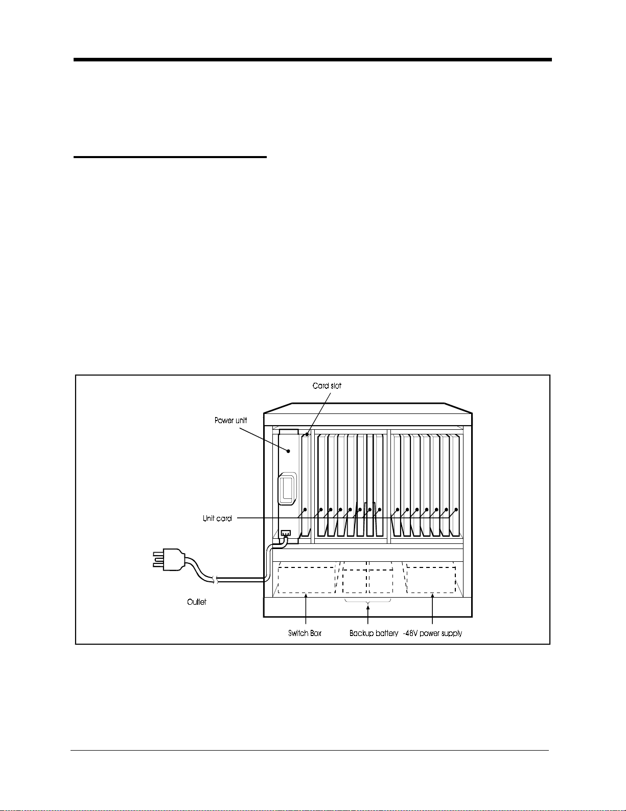
The DBS 576 cabinet includes the following:
• Power unit
• Card slots
• Unit cards (optional)
• Backup battery (VB-44025) (optional)
• Switch box (VB-44023) (One required per base cabinet with one or more
expansion cabinets att ache d)
• -48V Power Supply (VB-44022) (optional) (when one or more Ground
Start, DID or E&M cards are installed in this cabinet)
Figure 2-1. The DBS 576 Base Cabinet
Peripherals such as paging spe akers, external music-on-hold sources, background
music sources, PCs, printers, and SMDR connect to the unit cards.
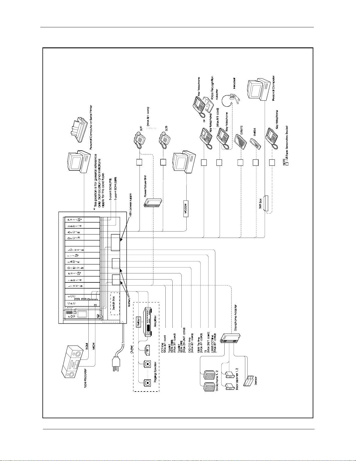
Figure 2-2 sh ows the t runk a nd extensi on li ne con nections a s well as som e periph eral
connections. Trunk and extensi on li ne conn ections a re cove red in de tail in Chapt er 5.
Peripheral connections are covered in detail in Chapter 6.
576-13-300 DBS 576 (USA), issued 6/2/98 2-1
Page 24
Chapter 2. System Overview Section 300-Installation
Figure 2-2. System Connections
2-2 DBS 576 (USA), issued 6/2/98 576-13-300
Page 25
Section 300-Installation Chapter 2. System Overview
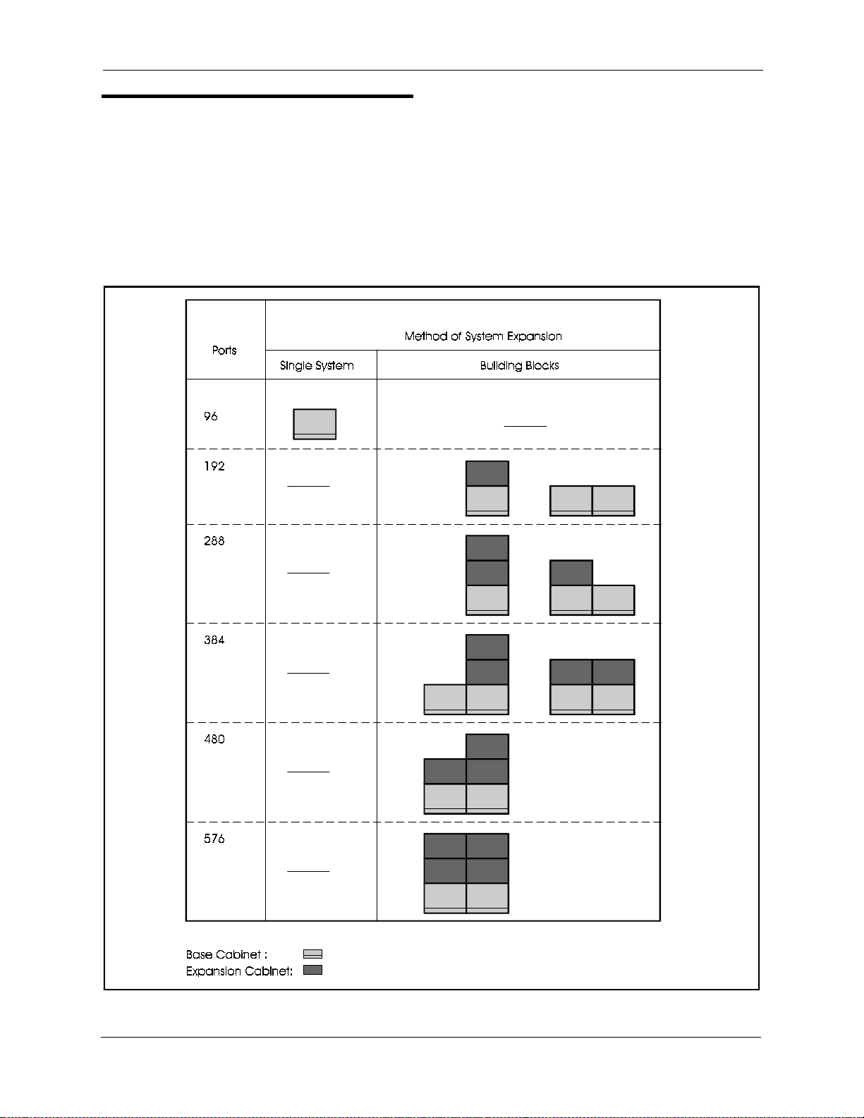
Cabinet Configurations
Two types of cabinets are used with the DBS 576. The DBS 576 base cabinet (VB-
44020) supports 96 ports. A DBS 576 system may contain up to two base cabinets.
Each base cabinet can be combined with up to 2 expansion cabinets (VB-44021) to
configure systems for up to 576 ports. They can also be combi ned with an existing
DBS to increas e the num ber of digit al exte nsion line ports. For det ails, see Chapter 4,
"Connection to DBS" (page 4-28).
Figure 2-3. Example Cabinet Combinations
576-13-300 DBS 576 (USA), issued 6/2/98 2-3
Page 26

Chapter 2. System Overview Section 300-Installation
Circuit Cards
Circuit Card Configuration
Table 2-1 shows the unit cards and packages that can be used with the DBS 576.
Table 2-1. Unit card configuratio n
Card Type Card Designation Product
Analog
Trunk
Digital
Trunk
Digital
Extension
Analog
Extension
Service
Circuit
Processor
Cards
DTMF
Circuits
Interface
cards
Time-Switch
Circuits
Audio
applications
Daughter
package
Loop Start Trunk Card LTRK/8 VB-44510 8-port loop-start trunk card An optional CID card can be
Loop Start/Ground Start
Trunk Card
DID Trunk Card DID/8 VB-44520 8-port DID trunk card Dial Pulse and DTMF
E&M Tie Line Trunk Card E&M VB-44560 4-port type 1/type 2 E&M tie line trunk
BRI Card TBRI/4 VB-44 530 T-point ISDN i nterface ports
PRI Card PRI/23 VB-44540 T-point ISDN primary interface port
T1 Card T1 VB-44550 24-circuit T1 interface card
Digital Extension Card DEC/8 VB-44610 8-port digital extension card
BRI Unit (S-Point) SBRI/4 VB-44630 S-poi nt ISDN interf ace ports
PRI Card PRI/23 VB-44540 T-point ISDN primary interface port
Analog Extension Card AEC/ 8 VB-44620 8-port analo g extens ion card
Service Control Card SCC VB-44181 Service circuit card (high level)
CPC-96 Card CPC96 VB-44410 Call processor card for 96 port system
CPC-288 Card CPC288 VB-444201 Call processor card for up to 288 port
CPC-576 Card CPC576 VB-4 44301 Call proc essor card for 576 port system
8 DTMF Receiver Card MFR/8 VB-44110 8-circuit DTMF receiver
Building B lock Expansi on
Card
Connection Cable Card-DBS CBLDBS VB-44452 DBS 576-to-DBS interface card Install in AUX slot of DBS.
Trunk MDF Card MDF-CO VB-44512 T runk MDF inter face card Mounts on si de of cabinet
Extension MDF Card MDF-EX VB-44611 Extension MDF interface card Mounts on side of cabinet
API Card API VB-44131 Applications Processor Interface card Data for External Integrated
8-Party Conference Card CONF VB-44120 Interface card for 8-party conference
Time Switch Card/288 TSW288 VB-444202 Time-switch circuit card (standard) Required with CPC288 card
Time Switch Card/576 TSW576 VB-444302 Time-s w itch circuit ca r d (high-level) Required with CPC576 c ard
Voice St or age Service Card VSSC VB-44170 2-way Voice storage cards
Voice Processing Card/4 VPU/4 VB-44160 V oice processing card
Voice Processing Card/8 VPU/8 VB-44150 Voice processing cards 8
ACD Card ACD VB-44140 Built-in ACD unit
Sync. Pac kage/Network Un it SYNC VB-44460 Network sync circuit unit (st a ndard) Mounts on CPC96,
Caller ID CID VB-44513 Caller ID interface card Mounts on LTRK/8 card
Name
LGTRK/8 VB-44511 8-port loop-start/ground start trunk card
CBL VB-44451 I nter fac e card for additiona l cabinet Mounts in CPC s lot of all but
Prod uc t No. Card Description Remarks
attached (see below)
card
and S-poi nt primary inte rface port
and S-poi nt primary inte rface port
Including Ringer circui t
RS232C po r t 2, BGM I/F
External paging I/F
(single cabinet)
system (up to 3 cabinets)
(up to 6 cab i n e t s )
interface
Built-in ACD voice 4 processing card
(4ch)
Supports up to 96 ports, 16
bit CPU
Supports up to 288 ports, 16
bit CPU
Supports up to 576 ports 32
bit CPU
first base cabinet
VM or ACD products
TSW288, or TSW576 card.
2-4 DBS 576 (USA), issued 6/2/98 576-13-300
Page 27
Section 300-Installation Chapter 2. System Overview
Card Descriptions
This section provides an overvi ew of each card to be inst alled in the main cabinet.
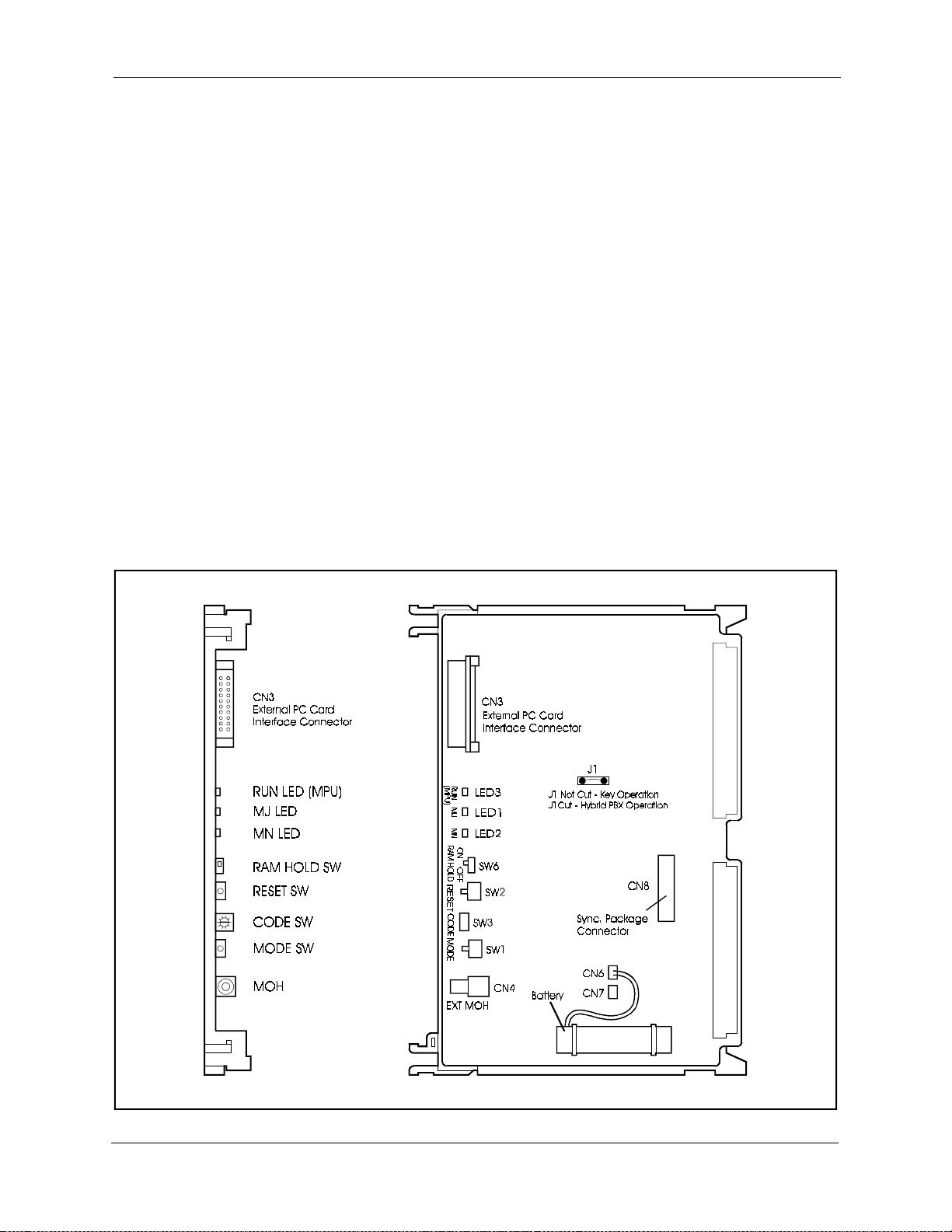
CPC96 card (VB-44410)
The CPC96 card is a high-level CPU card for a 96 port system. This card
incorporates a 16-bit CPU.
The CPC96 card provides a time switch (4 Highway x 4 Highway), a 4-circuit MFR
(DTMF receiver circuit), a 3-party conference circuit, service tone, a DTMF
transmitter, an input terminal for external hold tone source (RCA jack) , a connecting
terminal for synchronization package (VB-44460), an interface connector for
external PC card and modem (300 bps) functions. The system control program is
downloaded to the internal memory of the system through the PC card. Memory is
retained with a backup batt ery. (See “Replacing the Backup Battery of CPC card” on
page 6-29 for more information on battery replacement.)
Note:
Otherwise, the system will operate in Key mode.
Figure 2-4. CPC96 card
J1 must be cut for the system to operate in Hybrid/PBX mode.
576-13-300 DBS 576 (USA), issued 6/2/98 2-5
Page 28

Chapter 2. System Overview Section 300-Installation
Table 2-2 shows the switch settings and Table 2-3 shows the LED indicators.
Table 2-2. Switch settings of CPU96 card
SW No. Descripti on
SW1 : Black (MODE) Push switch for setting modes of syst em.
SW2 : Red (RESET) Push switch f or res etting.
SW3 : (CODE) Rotary switch for setting startup mode of system.
SW6 : (RAM HOLD) Switch for selecting bat te ry backup of memory.
Table 2-3. LED indication of CPC96 card
LED indication Description
LED3 (RUN) Flashes red when Main Processing Unit (MPU) is operating.
LED1 (MJ) Tur ns ON red when Major (MJ) alarm is dete ct ed.
LED2 (MN) Turns ON red when Minor (MN) alarm is detected.
2-6 DBS 576 (USA), issued 6/2/98 576-13-300
Page 29
Section 300-Installation Chapter 2. System Overview
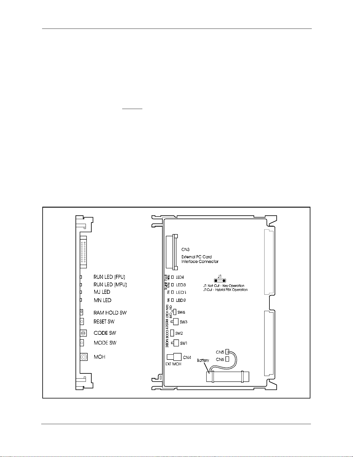
CPC288 card (VB-444201)
The CPC288 card is a standard C PU unit for a system with up to 288 ports. A 16-bit
CPU is incorporated.
The CPC288 card provides a 4-circui t MFR (DTMF receiver circuit), an input
terminal for external hold tone source (RCA jack), an interface connector for
external PC card and modem (300 bps) functions.
This card requires
The system control program is downloaded to the internal memory of the system
through the PC card.
Memory is retained with a backup battery. (See “Replacing the Backup Battery of
CPC card” on page 6-29 for more information on battery repla cement.)
The switch settings are li sted in Tabl e 2-4. The LED indicators are listed in Table 2-
5.
Note:
Otherwise, the system will operate in Key mode.
Figure 2-5. CPC288 card
the use of the TSW288 card (VB-444202).
J1 must be cut for the system to operate in Hybrid/PBX mode.
576-13-300 DBS 576 (USA), issued 6/2/98 2-7
Page 30

Chapter 2. System Overview Section 300-Installation
Table 2-4. Switch settings of CPC288 card
SW No. Descripti on
SW1 : Black (MODE) Push switch for setting modes of syst em.
SW2 : Red (RESET) Push switch f or res etting.
SW3 : (CODE) Rotary switch for setting startup mode of system.
SW6 : (RAM HOLD) Switch for selecting bat te ry backup of memory.
Table 2-5. LED indications of CPC288 card
LED indication Description
LED4 (RUN) Flashes red when (FPU) is operating.
LED3 (RUN) Flashes red when Main Processing Unit (MPU) is operating.
LED1 (MJ) Tur ns ON red when Major (MJ) alarm is dete ct ed.
LED2 (MN) Turns ON red when Minor (MN) alarm is detected.
2-8 DBS 576 (USA), issued 6/2/98 576-13-300
Page 31

Section 300-Installation Chapter 2. System Overview
CPC576 card (VB-444301)
The CPC576 card is a high-performance CPU unit for system with up to 576 ports. A
32-bit CPU is incorporate d.
The CPC576 card provides a 4-circui t MFR (DTMF receiver circuit), an input
terminal for music on hold tone sour c e (RCA jack), an interface connector for PCMCIA (PC card interface connector) and modem (300 bps) functi ons.
This card requires the use of the TSW576 card (VB-444302).
Memory is retained with a backup battery. (See “Replacing the Backup Battery of
CPC card” on page 6-29 for more information on battery repla cement.)
The system control program is downloaded to the internal memory of the system
through the PC Card (VB-44431). The PC Card is also necessary during normal
operating time (do not remove the PC Card).
Note:
Otherwise, the system will operate in Key mode.
CAUTION:
Figure 2-6. CPC576 card
J7 must be cut for the system to operate in Hybrid/PBX mode.
• A replacement Single Inline Memory Module (SIMM) is provided
through the service parts route. Panasonic does not take any
responsibili ty if a SIMM, ot her than Panasoni c se rvice p arts, or PC Card,
other than VB-44431 is connected to the CPC576 card.
576-13-300 DBS 576 (USA), issued 6/2/98 2-9
Page 32

Chapter 2. System Overview Section 300-Installation
Table 2-6 shows the switch settings of the CPC576 and Table 2-7 shows the LED
indications.
Table 2-6. Switch settings of CPC576 card
SW No. Descripti on
SW1 : Black (MODE) Push switch for setting modes of syst em.
SW2 : Red (RESET) Push switch f or res etting.
SW3 : (CODE) Rotary switch for setting startup mode of system.
SW6 : (RAM HOLD) Switch for selecting bat te ry backup of memory.
Table 2-7. LED indications of CPC576 card
LED indication Description
LED4 (RUN) Flashes red when FPU is operating.
LED3 (RUN) Flashes red when Main Processing Unit (MPU) is operating.
LED1 (MJ) Tur ns ON red when Major (MJ) alarm is dete ct ed.
LED2 (MN) Turns ON red when Minor (MN) alarm is detected.
2-10 DBS 576 (USA), issued 6/2/98 576-13-300
Page 33

Section 300-Installation Chapter 2. System Overview
TSW288 card (VB-444202)
The TSW288 card is the time switch card for the CPC288 card. The TS W288 card is
mounted on the option slot of the main cabinet. Only one TSW288 card can be
mounted for each system (maximum 288 ports).
When connecting to additiona l cabine ts, this card is cabled to the CBL card (VB-
44451) installed into CPC card slot of the additional cabinet(s).
The TSW288 card provides functions fo r a time switc h (14 Highways x 14
Highways), service tone, DTMF output, a connecting terminal for synchronization
package (VB-44460) and eight 3-party conference circuits.
Figure 2-7. TSW288 card
576-13-300 DBS 576 (USA), issued 6/2/98 2-11
Page 34

Chapter 2. System Overview Section 300-Installation
TSW576 card (VB-444302)
The TSW576 card is the time switch card required for the system using a CPC-576
card. This card supports a maximum of 576 ports.
The TSW576 card is mounted in the option 1 slot of the main cabinet. Only one
TSW576 card can be mounted for each system.
When connecting to additiona l cabine ts, this card and CBL card (VB-44451)
installed into CPC card slot of the additional cabinet are connected.
The TSW576 card provides functions fo r a time switc h (24 Highways X 24
Highways), service tone, DTMF output, a connecting terminal for synchronization
package (VB-44460), and eight 3-party conference circuits.
Figure 2-8. TSW576 card
2-12 DBS 576 (USA), issued 6/2/98 576-13-300
Page 35

Section 300-Installation Chapter 2. System Overview
CBL card (VB-44451): Building Block card
The CBL card is required for interconnecting cabinets in the DBS 576 system. The
TSW288 or TSW576 card is also necessary for the interconnection of cabinets
(building block connection).
The CBL card must be mounted in th e CPC slot of all cabinets other than the master
cabinet. A dedicated inter connect cable pair connects between cabi nets. The
connection to the master base cabinet is to the TSW288/TSW576 card, which is
mounted in the OP1 slot.
A rotary switch on the CBL card identifies the cabine t to the rest of the system (1 first additional cabinet, 2 - second additional cabinet, etc.). Up to 5 additional
cabinets can be installe d and each must be uniquely identified.
Figure 2-9. CBL card
Table 2-8 shows the LED indication.
Table 2-8. LED indications of CBL card
LED indication Description
LED1 (RUN) Flashes red when operating.
576-13-300 DBS 576 (USA), issued 6/2/98 2-13
Page 36

Chapter 2. System Overview Section 300-Installation
CBLDBS Card Kit (VB-44452): Connection Cable card-DBS
The CBLDB S kit includes an interface ca rd and cabl es for co nne ct ing bet w een the
DBS 576 and the DBS 96 cabinet and a new MDF interface ca rd for th e DBS.
The TSW288 / TSW576 card is necessary for connecting a DBS 576 to a DBS 96
cabinet.
The CBLDBS card must be mounted in the AUX1 slot of the DBS (AUX2 cannot be
used). A dedicated cable conne cts this card and the TSW288 / TSW576 card, which
is mounted on the OP1 slot of the Main Cabinet.
Only DEC cards can be installed in the DBS system.
Figure 2-10. CBLDBS interface card
Table 2-9 shows the LED indications.
Table 2-9. LED indications of CBLDBS card
LED indication Description
LED1 (RUN) Flashes red when FPU is operating.
2-14 DBS 576 (USA), issued 6/2/98 576-13-300
Page 37

Section 300-Installation Chapter 2. System Overview
The CBLDB S interface card provide s connection points between the DBS and the
MDF.
Figure 2-11. CBLDBS MDF card
576-13-300 DBS 576 (USA), issued 6/2/98 2-15
Page 38

Chapter 2. System Overview Section 300-Installation
EXT MDF card (VB-44611): Extension MDF Interface Card
The EXT MDF card provides a standard 25-pair conne ction at the DBS 576 Cabinet.
This interface boar d insta lls in one of five possible positions on either sid e of the
DBS 576 Cabinet and supports up to three exte nsion cards (either DEC/8 or AEC/8).
Since each extension card contains 8 extension ports, the EXT MDF supports a
maximum total of 24 extensions.
A standard 25-pair cable must be run from this int erface board to the MDF.
Figure 2-12. EXT MDF Interface card
2-16 DBS 576 (USA), issued 6/2/98 576-13-300
Page 39

Section 300-Installation Chapter 2. System Overview
TRK MDF card (VB-44512): Trunk MDF Interface Card
The TRK MDF card provides a standard 25- pair co nnection at the DBS 576 Cabine t.
This interface boar d insta lls in one of five possible positions on either sid e of the
DBS 576 Cabinet and supports up to three trunk cards (LTRK/8, LGTRK/8 or
DIDTR/8). Since e ach of t hese trunk c ards c ontains 8 exte nsion por ts, the TRK MDF
supports a maximum total of 24 trunks.
A standard 25-pair cable must be run from this int erface board to the MDF.
Figure 2-13. TRK MDF Interface card
576-13-300 DBS 576 (USA), issued 6/2/98 2-17
Page 40

Chapter 2. System Overview Section 300-Installation
SYNC Package (VB-44460): SYNC Package/Network Unit
The SYNC package supplie s a networ k synchr onizing cir cuit, and is re quire d when a
digital circui t, suc h as ISDN, is used.
The SYNC package generates a PCM clock that is synchronized with a digital
network by the PLL circuit, supplying the PCM clock to the TSW288 / TSW576
card or CPC96 card.
The SYNC package is mounted on either the CPC96 card or the TSW288/TSW576
card.
For details on how to mount the SYNC package, see page 5-20.
Figure 2-14. SYNC Package
Table 2-10 shows the LED indications.
Table 2-10. LED indications of SYNC package
LED indication Description
LED1 (SYNC) Turns on when synchronizing to the CO clock.
2-18 DBS 576 (USA), issued 6/2/98 576-13-300
Page 41

Section 300-Installation Chapter 2. System Overview
SCC card (VB-44181): Service Control Card
The SCC card is used to extend se rvice functions. This card is mount ed in the option
slot to support RS-232C port contr ol, background music (BGM) input and external
paging (external paging with talkback) control.
Only one SCC card can be mounted for each system.
The major specifications of this card follow:
• RS-232C port: 2 ports (max. 9600 bps)
CN5: SMDR or customized tool
CN6: Bus monitor
• BGM input terminal: 1 port (with RCA jack)
• External paging input terminal
• External amplifier ON/OFF control: 1 contact
• Number of contacts for external equipment ON/OFF control: 5 contacts
• Maximum drive current controlling ports for external equipment control board:
25mA (Total)
Figure 2-15. SCC card
576-13-300 DBS 576 (USA), issued 6/2/98 2-19
Page 42

Chapter 2. System Overview Section 300-Installation
Table 2-11 shows the switch settings.
Table 2-11. SCC card switch settings.
Switch No. Setting Description
SW1 CTM Connects customized tool to RS-232C port (CN5).
SMDR Connects SMDR to RS-232C port (CN5) (default)
SW2 ON Sets input impedance of exte rnal paging device to 600
Ohms
.
OFF Sets input impedance of external paging devic e to high impedance. (This is
set before shipping.)
2-20 DBS 576 (USA), issued 6/2/98 576-13-300
Page 43

Section 300-Installation Chapter 2. System Overview
LTRK / 8 card (VB-44510): Loop Start Trunk Card
The LTRK/8 car d is an interface that accommod at e s loop star t ty pe ana log tru nks .
This card is mounted on a flexible slot to connect analog telephone lines. An optiona l
“piggyback” daughter circuit card (VB-44513) may be installed on this card to
receive Caller ID. See “CID card (VB-44513) : Caller ID Interface Card” on page 223 for more information.
The LTRK/8 card provides 8 circuit trunk interface, detection and answering of call
signals from the trunk, sendi ng signals to the trunk, dialing and speech.
The LTRK/8 card provides a lightening arrester and a safety circ uit to directly
connect with general telephone lines.
Figure 2-16. LTRK/8 card
576-13-300 DBS 576 (USA), issued 6/2/98 2-21
Page 44

Chapter 2. System Overview Section 300-Installation
Table 2-12 and Table 2-14 show the switch settings and LED indications.
Table 2-12. Maintenance switch (SW1) settings of LTRK/8 card
Setting Description
ON Card is in cl osed status, and can be mounted and removed when power is ON. (Send-
ing/receiving of calls is disabled. If this is set while a trunk is in use, sending/receiving of calls is disabled afte r the call ends.)
OFF (M-SW) Norm al operation (This switch is set to OFF for normal operation.)
Table 2-13. Caller ID switch (SW10-17) settings of LTRK/8 card
Switch Setting Description
SW10 ON Circuit 1 is in loop start mode and does not receive calle r ID inform ation.
OFF Circuit 1 is set to receive Caller ID information (requires CID card).
SW11 ON Circuit 2 is in loop start mode and does not receive calle r ID inform ation.
OFF Circuit 2 is set to receive Caller ID information (requires CID card).
SW12 ON Circuit 3 is in loop start mode and does not receive calle r ID inform ation.
OFF Circuit 3 is set to receive Caller ID information (requires CID card).
SW13 ON Circuit 4 is in loop start mode and does not receive calle r ID inform ation.
OFF Circuit 4 is set to receive Caller ID information (requires CID card).
SW14 ON Circuit 5 is in loop start mode and does not receive calle r ID inform ation.
OFF Circuit 5 is set to receive Caller ID information (requires CID card).
SW15 ON Circuit 6 is in loop start mode and does not receive calle r ID inform ation.
OFF Circuit 6 is set to receive Caller ID information (requires CID card).
SW16 ON Circuit 7 is in loop start mode and does not receive calle r ID inform ation.
OFF Circuit 7 is set to receive Caller ID information (requires CID card).
SW17 ON Circuit 8 is in loop start mode and does not receive calle r ID inform ation.
OFF Circuit 8 is set to receive Caller ID information (requires CID card).
Table 2-14. LED indications of LTRK/8 card
LED indication Description
LED1 (LINE BUSY) Turns ON when any trunk on the card is in use.
2-22 DBS 576 (USA), issued 6/2/98 576-13-300
Page 45

Section 300-Installation Chapter 2. System Overview
CID card (VB-44513): Caller ID Interface Card
The Caller ID card is an interface that attaches to the loop start card (VB-44510) and
receives Caller ID infor mation.
The CID card provides 8 circuits. DIP swit ches on the Loop Start Card must be
properly set for CID to operate. (See “LTRK / 8 card (VB-44510): Loop Start Trunk
Card” on page 2-21 for more information.
Figure 2-17. CID card
576-13-300 DBS 576 (USA), issued 6/2/98 2-23
Page 46

Chapter 2. System Overview Section 300-Installation
LGTRK / 8 card (VB-44511): Loop Start/Ground Start Trunk
Card
The LGTRK/8 card is an interface that accommodates both loop start type analog
trunks and ground start analog tr unks. Each trunk circuit type (either ground sta rt or
loop start) is specif ied by a program setting as well as by two jumpers settings.
This card is mounted on a flexible slot to connect general analog telephone lines.
The LGTRK/8 card provides an 8 circuit trunk interface and can serve the functions
of detection and answering of call signals from the trunk, sending call signals to the
trunk, dialing and speech.
The LGTRK/8 card provides a lightening arrester and a safety circuit to directl y
connect with general telephone lines.
Note:
To use the LGTRK/8 card, a built-in -48V power supply is required in
the same cabinet. The -48V power supply signal gr ound (SG) connector must
be properly connected to ground for the ground start trunks to operate
correctly.
Each circuit has two jumper connectors (CNX01 and CNX02). When jumpers are
installed on both jumper connectors, the circuit is set for Ground Start operation.
When the jumpers are not installed, the circuit is set of Loop start operation.
Table 2-15. Ground Start/Loop Start jumper settings of LGTRK/8 card
Jumper
Connector
CN101 & CN102 ON Circuit 1 is in ground start mode
CN201 & CN202 ON Circuit 2 is in ground start mode
CN301 & CN302 ON Circuit 3 is in ground start mode
CN401 & CN402 ON Circuit 4 is in ground start mode
CN501 & CN502 ON Circuit 5 is in ground start mode
Jumper Description
OFF Circuit 1 is in loop start mode
OFF Circuit 2 is in loop start mode
OFF Circuit 3 is in loop start mode
OFF Circuit 4 is in loop start mode
OFF Circuit 5 is in loop start mode
CN601 & CN602 ON Circuit 6 is in ground start mode
OFF Circuit 6 is in loop start mode
CN701 & CN702 ON Circuit 7 is in ground start mode
OFF Circuit 7 is in loop start mode
CN801 & CN802 ON Circuit 8 is in ground start mode
OFF Circuit 8 is in loop start mode
2-24 DBS 576 (USA), issued 6/2/98 576-13-300
Page 47

Section 300-Installation Chapter 2. System Overview
The switch settings and LED indicat ions are the same as for the LTRK/8 card (VB-
44510). See Table 2-12 and Table 2-14.
Figure 2-18. LGTRK/8 card
576-13-300 DBS 576 (USA), issued 6/2/98 2-25
Page 48

Chapter 2. System Overview Section 300-Installation
DID/8 card (VB-44520): DID Trunk Card
The DID/8 card is a trunk interface that accommodates cards for the DID dedicated
incoming function.
The incoming c all address rece iving c ontrol sys tem s upports the i mmediat e and win k
method, and supports DP (10 PPS) and DTMF (only for wink) as incoming call
address signals. However, an MFR is required when the DTMF is selecte d. MFR is
supplied in C PC96, CPC288 and CPC576 card . Additional MFRs are available in an
MFR/8 card.
The DID/8 card is mounted on a flexible slot to connect to a DID telephone line,
making detection and answering of call signals from the trunk and speech possible.
The DID/8 card provides an 8-circuit trunk interface on the card, and a lightening
arrester to directly connect to a DID telephone line.
Note:
same cabinet.
The switch settings and LED indicat ions are the same as for the LTRK/8 card (VB-
44510). See Table 2-12 and Table 2-14.
Figure 2-19. DIDTR 8 card
To use the DID/8 card, a built-in -48V power supply is required in the
2-26 DBS 576 (USA), issued 6/2/98 576-13-300
Page 49

Section 300-Installation Chapter 2. System Overview
E&M/4 card (VB-44560): E&M Trunk Card
The E&M/4 card is a trunk interface that accommodates cards for the E&M Tie line
connections. Typically, tie trunks are used in network connections and for dire ct
connections to other PBX systems.
The incoming c all address rece iving c ontrol sys tem s upports the i mmediat e and win k
method, and supports DP (10 PPS) and DTMF (only for wink) as incoming call
address signals. However, an MFR is required when the DTMF is selecte d. MFR is
supplied in C PC96, CPC288 and CPC576 card . Additional MFRs are available in an
MFR/8 card.
The E&M/4 card is mounted on a flexible slot to connect to a E&M telephone line.
The E&M/4 card provides a 4-circuit trunk interface on the card, and a lightening
arrester to directly connect to a E&M telephone line.
Note:
same cabinet.
Figure 2-20. E&M/4 card
T o use the E&M/4 card, a built-in -48V power supply is required in the
576-13-300 DBS 576 (USA), issued 6/2/98 2-27
Page 50

Chapter 2. System Overview Section 300-Installation
TBRI/4 card (VB-44530): BRI Card (T-point)
The TBRI/4 car d is a T-p o int ISD N bas ic interface (2 B + D: 192 kbps)
accommo dat ion card.
The TBRI/4 card is mounted on a flexible slot to control the basic user network
interface of ISDN.
The TBRI/4 card is connected through a Network Termination Unit (NT1) to the
ISDN trunk which supports the T-point I SDN basic interface. (Th e NT1 is not
provided.)
This card has an on -bo ard , 4-circ u it T-p o int ISD N bas ic interface, and a lightening
arrester built-in, and also provides a network clock synchronizing function.
Figure 2-21. TBRI/4 card
Tables 2-1 1, 2- 12 and 2-13 show the switch settings and LED indications.
2-28 DBS 576 (USA), issued 6/2/98 576-13-300
Page 51

Section 300-Installation Chapter 2. System Overview
Table 2-16. Maintenance switch (SW4) settings of TBRI/4 card
Setting Description
ON Card is in closed status, and can be mounted and remove d when the power is ON.
(Sending/receiving of calls is disabled. If this is set during speech, sending/receiving
of calls is disabled after speech ends.)
OFF Normal operation (This switch is set to OFF for normal operation.)
Table 2-17. Circuit select switch (SW1) settings of TBRI/4 card
Switch Position Description
0 OFF (default setting when unit is shippe d)
1 1st interface condition displayed by LAYER1 LED and LAYER2 LED
2 2nd interface condition displayed by LAYER1 LED and LAYER2 LED
3 3rd interface condition displayed by LAYER1 LED and LAYER2 LED
4 4th interface condition displayed by LAYER1 LED and LAYER2 LED
5 to 7 Not used
Table 2-18. LED indication of TBRI/4 card
LED indication Description
LED1
Turns ON when trunk is in use.
(LINE BUS Y)
LED2
Turns ON when network synchronization clock is sent.
(SYNC)
LED3
Turns ON when synchronization is established.
(LAYER1)
LED4
Turns ON when data link (DL) is esta blished.
(LAYER2)
576-13-300 DBS 576 (USA), issued 6/2/98 2-29
Page 52

Chapter 2. System Overview Section 300-Installation
PRI/23 card (VB-44540): PRI Card
The PRI/23 card is a T-p o int ISD N prim ar y group interface (23B + D/24B: 1544
kbps) and also an S-point ISDN primary group interface accommodation card.
The PRI/23 card is mounted on a flexible slot to connect the system to ISDN (to
access ISDN services). It is possible to use either the T- or S-point ISDN primary
group interface by setting a switch on the card or by a program setting. By selecting
the mode switch on the c ard, 8/16/24 channel modes c an be se lected, however , there
are restrictions to the position of the slot to which the card is mounted. This depends
on the number of accommodating channels. For details on th e res trictions of the slot
position, see page 2-39.
A maximum of three cards can be mounted in each cabinet. When there are six
cabinets, a maximum of 18 cards can be mounted.
The PRI/23 card has an on -bo ard lightening arrester, so that the card can be
connected to t he carri er trunk corresponding to the T-point primary group interface
through a CSU. (The CSU is not provided.)
This clock provides a network clo ck synchr onizing function.
2-30 DBS 576 (USA), issued 6/2/98 576-13-300
Page 53

Section 300-Installation Chapter 2. System Overview
Figure 2-22. PRI/23 card
Tables 2-14 to 2-17 show the switch settings and LED indications.
Table 2-19. Maintenance switch (SW4) settings of PRI/23 card
Setting Descripti on
ON Card is in closed status, and can be mounted a nd removed when power is ON. ( Send-
ing/receiving of calls is disabled. If this is set during speech, sending/receiving of
calls is disabled after speec h ends.)
OFF Normal operation (This switch is set to OFF for normal operation.)
Table 2-20. Dip switch (SW1) settings of PRI/23 card
Switch No. Distance from the DBS 576 to the CSU
0 to 150 ft. 150-450 ft. 450-655 ft.
SW1-1 ON OFF OFF
SW1-2 OFF ON OFF
SW1-3 OFF OFF ON
SW1-4 OFF ON OFF
SW1-5 OFF OFF ON
SW1-6 OFF ON OFF
SW1-7 OFF OFF ON
SW1-8 Not used
576-13-300 DBS 576 (USA), issued 6/2/98 2-31
Page 54

Chapter 2. System Overview Section 300-Installation
Table 2-21. Dip switch (SW2) settings of PRI/23 card
Switch No. Description
SW2-1 ON Sets to "trunk" for T-point.
OFF Sets to "extension line" for S-point .
SW2-2 ON Sets to "other mode" where 1 to 16B+D or 1 to 23B+D channels set by pro-
gram can be used.
OFF Sets to "8ch mode" where 1 to 8B+D channels can be used.
Table 2-22. LED indications of PRI/23 card
LED indication Description
LED1
Turns ON red when B channel is in use.
(LINE BUS Y)
LED8
Turns ON red when set to adstracting Network synchronizing clock.
(SYNC)
LED3
Turns ON red when SLIP abnormality is detected.
(SLIP)
LED6
Turns ON red when receiving YELLOW alarm signal.
(YEL/RA1)
LED4
Turns ON red when receiving AIS signal.
(AIS)
LED7
Turns ON red during RED alarm.
(CFA)
LED5
Turns ON red when fram e fai lu re is d etect ed.
(OOF)
LED2
Turns ON red when data receiving failure is detected.
(LOOP)
2-32 DBS 576 (USA), issued 6/2/98 576-13-300
Page 55

Section 300-Installation Chapter 2. System Overview
T1 Interface card (VB-44550)
The T1 Interface card is mounted in a flexible slot to connect the system to T1
services. By selecting the mode switch on the card, 8/16/24 channel modes can be
selected, however, there are restrictions to the positi on of the slot to whic h the card is
mounted. This depends on the number of accommodating channels. For details on
the restrictions of the sl ot position, see page 2-39.
A maximum of three cards can be mounted per cabinet. When there are six cabinets,
a maximum of 18 cards can be mounted.
The T1 card has an o n-b oard lightening arreste r, so that the card can be connected to
the carrier trunk through a CSU (not provided).
This card requires the system sync circuit card be installed for cl ock synchroni zatio n.
Figure 2-23. T1 card
Table 2-23, Table 2-24, and Table 2-25 show the switch settings and Table 2-26
shows the LED indications.
576-13-300 DBS 576 (USA), issued 6/2/98 2-33
Page 56

Chapter 2. System Overview Section 300-Installation
Table 2-23. Maintenance switch (SW3) settings of T1 card
Setting Descripti on
ON Card is in closed status, and can be mounted a nd removed when power is ON. ( Send-
ing/receiving of calls is disabled. If this is set during speech, sending/receiving of
calls is disabled after speec h ends.)
OFF Normal operation (This switch is set to OFF for normal operation.)
Table 2-24. Dip switch (SW1) settings of T1 card
Switch No. Distance from the DBS 576 to the CSU
0 to 150 ft. 150-450 ft. 450-655 ft.
SW1-1 ON OFF OFF
SW1-2 OFF ON OFF
SW1-3 OFF OFF ON
SW1-4 OFF ON OFF
SW1-5 OFF OFF ON
SW1-6 OFF ON OFF
SW1-7 OFF OFF ON
SW1-8 Not used
Table 2-25. Dip switch (SW2) settings of T1 card
Switch No. Description
SW2-1 ON Not used
OFF Not used
SW2-2 ON Sets to "other mode" where 1 to 16 or 1 to 24 channels set by program can be
used.
OFF Sets to "8ch mode" where 1 to 8 channels can be used.
Table 2-26. LED indications of T1 card
LED indication Description
LED1
Turns ON red when B channel is in use.
(LINE BUS Y)
LED8
Turns ON red when set to adstracting Network synchronizing clock.
(SYNC)
LED3
Turns ON red when SLIP abnormality is detected.
(SLIP)
LED6
Turns ON red when receiving YELLOW alarm signal.
(YEL/RA1)
LED4
Turns ON red when receiving AIS signal.
(AIS)
LED7
Turns ON red during RED alarm.
(CFA)
LED5
Turns ON red when fram e fai lu re is d etect ed.
(OOF)
LED2
Turns ON red when data receiving failure is detected.
(LOOP)
2-34 DBS 576 (USA), issued 6/2/98 576-13-300
Page 57

Section 300-Installation Chapter 2. System Overview
DEC/8 card (VB-44610): Digital Extension Card
The DEC/8 card is an interface accommodating card for digital key telephones
(1B+D: 64 kbps + 16 kbps).
The DEC/8 card is mounted in a flexible slot to connect digital extension line
terminals (1B+D: digital multi-function telephones and DSS). This card
accommodates an on-boa rd 8-ci rcui t extension p ort interface. The connection format
is 2-wire non-polari zed home run (sta r) wiring.
The major specifications on wiring are as follows:
• Supply voltage and current to telephone terminal: maximum +24V/200mA
• Allowable wiring distance: maximum 40 ohms with loop to terminal
• Maximum 20 Ohms with loop to DSS/72, EM/24, and Voice Recognition
Telephone.
Figure 2-24. DEC/8 card
576-13-300 DBS 576 (USA), issued 6/2/98 2-35
Page 58

Chapter 2. System Overview Section 300-Installation
AEC/8 card (VB-44620): Analog Extension Card
The AEC/8 card is an extension line interface accommodating unit for standard
telephones (SLT). The AEC/8 card is mounted on a flexible slot to connect a
standard telephone (SLT) to the system.
The AEC/8 card has an 8-circuit analog extension line interface, and provid es such
functions as call signals from a standard SLT, detection of dialing (10 pps/DTMF)
and speech.
The supply voltage to a standard SLT is +24V, and a ringer circuit is built-in.
The duration of one callup signal from the built-in ringer circuit is a maximum one
second. Control is in three phases when eight trunks are simultaneously cal led up:
the first phase for the fir st to thir d circuits, the second phase for the fourth to sixth
circuit, and the third phase for the seventh and eighth circuits.
The major specifications on wiring are as follows:
• Supply voltage/current for speech pat h: +24 V/25mA or more
• Loop resistance: 100 Ohms or less
• Ringer signal frequency: 20Hz rectangular wave
• REN: 2
• CPC (Positive AEC Disconnect) control possible
• Ring trip detection possible
Figure 3-25. AEC/8 card
2-36 DBS 576 (USA), issued 6/2/98 576-13-300
Page 59

Section 300-Installation Chapter 2. System Overview
SBRI/4 card (VB-44630): BRI Card (S-point)
The SBRI/4 card is a basic interface (2B+D: 192Kbps) accommodating card for Spoint IDSN.
The SBRI/4 card is mounted on a flexible slot to accommodate terminal extension
lines of the basic user network interface of an ISDN terminal.
The system supplies +40V to the ISDN terminal whic h is mounted fo r extension
lines.
The SBRI/4 card has an on-board 4-circuit S-point ISDN basic interface, and a
lightening arrester.
Figure 3-26. SBRI/4 card
576-13-300 DBS 576 (USA), issued 6/2/98 2-37
Page 60

Chapter 2. System Overview Section 300-Installation
Table 2-27 and Table 2-28 show the switch settings and LED indications.
Table 2-27. Settings of circuit selection switch of SBRI/4 card
Switch Position LED Indication
0 OFF (default setting when unit is shippe d)
1 1st interface condition displayed by LAYER1 LED and LAYER2 LED
2 2nd interface condition displayed by LAYER1 LED and LAYER2 LED
3 3rd interface condition displayed by LAYER1 LED and LAYER2 LED
4 4th interface condition displayed by LAYER1 LED and LAYER2 LED
5 to 0 Not available
Table 2-28. LED indications of SBRI/4 card
LED indication Description
LED3
(LAYER1)
LED4
(LAYER2)
Turns ON when synchronization is established
Turns ON when DL is establis hed
2-38 DBS 576 (USA), issued 6/2/98 576-13-300
Page 61

Section 300-Installation Chapter 2. System Overview
MFR/8 card (VB-44110): 8 DTMF Receiver Card
The MFR/8 card is a receiving circuit accommodating card for DTMF signals.
The MFR/8 card is mounted in an option slot or flexible slot to receive DTMF
signals which are sent from a standa rd tele phone (SLT) to an extension line. The
MFR/8 card also can receive DTMF signals sent from a trunk.
The MFR/8 card provides an on-board 8-cir cu it DTMF receiver circuit. Only one
card can be mounted for each cabi net. Table 2-29 shows the relationship betwee n the
number of system ports and the maximum number of DTMF cards.
Table 2-29. Mounting restriction of MFR/8 card
Port number 96 to 192 192 to 288 288 to 384 384 to 480 480 to 576
Maximum number
of cards
Figure 3-27. MFR/8 card
23456
576-13-300 DBS 576 (USA), issued 6/2/98 2-39
Page 62

Chapter 2. System Overview Section 300-Installation
CONF card (VB-44120): Conference Card
The CONF card is a conference speech card.
The CONF card is mounted in a flexible slot to support two eight-party conferences.
Figure 3-28. CONF card
CAUTION:
• Don’t change the switches on the CONF card from the default setting.
SW1, SW2 and SW3 must be set "OFF".
Otherwise, the mounting slot position of the CONF card and othe r cards
are restricted.
2-40 DBS 576 (USA), issued 6/2/98 576-13-300
Page 63

Section 300-Installation Chapter 2. System Overview
ACD card (VB-44140): ACD card
The ACD card is an Automatic Call Distribution (ACD) card which is mounted in
the main cabinet.
By using the ACD card wi th on e VPU/4 card (VB -44160) , sim plified AC D func tions
such as the incoming call distr ibuting function and processed call number
information for each terminal can be supported.
MIS reports may be sent output through an RS-232C port to either a printer or PC
computer. This port is mounted in the ACD unit. This port requires a dedicated RS232C cable.
Only one ACD card can be mounted for each cabinet. A maximum of two ACD
cards may be used in a system.
The ACD card option and the build in voice mail option cannot be installed in the
same cabinet.
For more information on the ACD card installati on an d the A CD op tion in general,
see Section 520 - ACD Reference.
Figure 3-29. ACD card
The following tables show the switch settings and LED indications.
576-13-300 DBS 576 (USA), issued 6/2/98 2-41
Page 64

Chapter 2. System Overview Section 300-Installation
Table 2-30. ACD Card Switch Settings
Switch No. Setting Description
SW1 BACK UP Set when retaining RAM data.
INITIAL Set when clearing RAM data.
SW2 ON LINE Normal operation (set to ON LINE during regular operation)
OFF LINE Not used.
Table 2-31. ACD Card LED Indications
LED Display Description
LED1
(CPU RUN)
Blinks when the CPU is in operation.
2-42 DBS 576 (USA), issued 6/2/98 576-13-300
Page 65

Section 300-Installation Chapter 2. System Overview
VPU/4 card (VB-44160): 4-voice Processing card
The VPU/4 card can support simplifi ed voice mail functions by using this card with
the VSSC card (VB-44170). This card c an a lso be used as a voi ce proce ssing card for
ACD when combined with the ACD card (VB-44140).
Two types of VPU card s are avai l abl e; the VPU/8 card and the VPU/4 (VB-44150).
The VPU/8 provides 8 voice paths to the voic e mail system while the VPU provides
4 voice paths. Up to two VPUs of any type may be installed along with a VSSC card
in a single cabinet to support built- in voice mail.
The VPU/4 card and ACD card (VB-44140) may be installed together in a sing le
cabinet to support ACD.
Figure 3-30. VPU/4 card
The following table describes LED indications.
Table 2-32. VPU/4 Card LED Indication
LED Display Description
LED1-LED4
(RUN)
576-13-300 DBS 576 (USA), issued 6/2/98 2-43
Blinks when the CPU is in operation.
Page 66

Chapter 2. System Overview Section 300-Installation
VPU/8 card (VB-44150): 8-voice Processing card
The VPU/8 card is a voice processing car d for voice mail (t wo-way), and is mounted
in the main cabinet.
Two types of VPU card s are avai l abl e; the VPU/8 and the VPU/4 (VB-44150). The
VPU/8 provides 8 voice paths to the voice mail system while the VPU provides 4
voice paths. Up to two VPUs of any type may be installed in a single cabinet and
must be combined with the VSSC card (VB-44170) to support voice mail.
The VPU/8 card cannot be used with the ACD card (VB-44140).
Figure 3-31. VPU/8 card
The following table describes LED indications.
Table 2-33. VPU/8 Card LED Indication
LED Display Description
LED1-LED8
(RUN)
2-44 DBS 576 (USA), issued 6/2/98 576-13-300
Blinks when the CPU is in operation.
Page 67

Section 300-Installation Chapter 2. System Overview
VSSC card (VB-44170): Voice Storage Service card
The VSSC card is a voice s tor ag e card for built-in voice mail (two-way), and is
mounted in the main cabinet.
The VSSC card provides a hard disk to st or e voice data of voice mai l. This c ard must
be combined with one or two VPU cards (VPU/8 card and/or VPU/4 card).
Only one VSSC card can be mounted in each cabinet.
This card must be inst alled into FS1 1. FS 12 must be left vaca nt. A maximum of four
VSSC cards can be mounted in a single system..
The VSSC card and the ACD card (VB-44140) cannot be used together in the same
cabinet.
For more information on the Built- in voice mail option, see Section 510 - Built-In
Voice Mail Reference Manual.
Figure 3-32. VSSC card
The following tables show the switch settings and LED indications.
Note:
The Hard Disk Drive and the back up battery must be replaced every
three years.
576-13-300 DBS 576 (USA), issued 6/2/98 2-45
Page 68

Chapter 2. System Overview Section 300-Installation
Table 2-34. VSSC Card Switch Settings
Switch No. Setting Description
SW1 BACK UP Set when retaining RAM data.
INITIAL Set when clearing RAM data.
SW2 ON LINE Normal operation (set to ON LINE during regular operation)
OFF LINE Set when replacing the HDD system.
Table 2-35. VSSC Card LED Indications
LED Display Description
LED1
Blinks when the CPU is in operation.
(CPU RUN)
LED2 Not used.
LED3 Not used.
2-46 DBS 576 (USA), issued 6/2/98 576-13-300
Page 69

Section 300-Installation Chapter 2. System Overview
API card (VB-44131)
The API card is an interface card for applications such as voice mail and ACD.
The external interface is an RS-232C port (maximum 19200 bps).
Only one API card can be mounted for each system. This sheet is mounted to on
option slot (OP1 or OP2) or on an expansion slot (FS1 to FS12).
Figure 3-33. API card
Tables 2-21 to 2-23 show the switch settings and LED indications.
Table 2-36. Maintenance switch (SW1) settings of API card
Setting Description
ON (top) Card is closed and can be mounted and removed when power is ON. (Sending/
receiving of calls is disa bled. If this is set during spe ech, sen ding/receiving of calls is
disabled after speech ends.)
OFF (bottom) Normal operation (This switch is set to OFF for normal operation.)
576-13-300 DBS 576 (USA), issued 6/2/98 2-47
Page 70

Section 300-Installation Chapter 2. System Overview
Table 2-37. Internal diagnosis switch (SW2) settings of API card
Setting Descripti on
ON (top) Normal operation (This switch is set to ON for normal operation.)
OFF (bottom) Normal operation (This switch is set to OFF for normal operation.)
Table 2-38. Memory backup switch (SW3) settings of API card
Setting Descripti on
ON (top) Self-diagnosis API car d
OFF (bottom) Can delete memory data of API card.
Table 2-39. LED indications of API card
LED indication Description
LED1
(RUN)
Flashes green when LPU is operating.
576-13-300 DBS 576 (USA), issued 6/2/98 2-48
Page 71

Chapter 3. Cabinet Installation
This chapter explains how to prepare for a singl e cabinet insta llation , how to remove
and replace the cabinet cover, install the bat tery and install cards.
Installation Location
Guidelines
• Before deciding where to install the single base cabinet, check the external
dimensions shown below, the area required for maintenance, and the
"Environmental Conditions" described in Chapter 1 (page 1-4).
Figure 3-1. Single base cabinet dimensions and maintenance area
Notes
576-13-300 DBS 576 (USA), issued 6/2/98 3-1
o
:
Hatched area indicates the area that should be provided for maintenance.
o
The dimensions shown in parenthesis indicate the dimensions required
when the MDF interface cable is wired from the right of the cabinet.
Page 72

Chapter 3. Cabinet Installation Section 300-Installation
Removing and Replacing Covers
Guidelines
CAUTION:
• Turn the power switch and the externa l breaker OFF, and disconnect the
AC cable before removing any covers.
• Both left and right side covers can be removed. The following describes how to
install and remove the left side cover. The identical procedure can be used for the
right side cover.
• Replace the respective covers after the installation work has been completed.
3-2 DBS 576 (USA), issued 6/2/98 576-13-300
Page 73

Section 300-Installation Chapter 3. Cabinet Installation
Front Cover
Installation
Removing the front cover
1. Remove the four screws from the front cover.
2. Pull the bottom of the front cover out by about 3/4”.
Note: Do not exert excessive force when pulling out the bottom of the front c over
as doing so may distort the claw slots.
3. Gently lift the cover off by sliding it up and away.
Replacing the front cover
1. Hook the front cover onto the front cover mounting claws of the cabinet.
2. Secure the four screws.
Figure 3-2. Removing and replacing front cover of base cabinet
576-13-300 DBS 576 (USA), issued 6/2/98 3-3
Page 74

Chapter 3. Cabinet Installation Section 300-Installation
Side cover
Installation
Removing the side cover
Note: The front cover must be removed before the side cover may be removed.
1. Remove the two screws from the side cover.
2. Open the edge (with the screws) of the cover about 1”.
Note: Do not exert excessive force when pulling out the side cover as doing so may
damage the claw slots.
3. Gently lift the cover off by sliding it forwards.
Replacing the side cover
1. Hook the side cover onto the top and bottom side cover mounting claws of the
cabinet.
2. Secure the two screws.
Figure 3-3. Removing and replacing side cove r of base cabinet
3-4 DBS 576 (USA), issued 6/2/98 576-13-300
Page 75

Section 300-Installation Chapter 3. Cabinet Installation
T op Cover (Base Cabinet Only)
Installation
Removing the top cover
Note: The front cover must be removed before the top cover may be removed.
1. Remove the two screws from the top cover.
2. Pull the top cover out about 2”.
Note: Do not exert excessive force when pulling the top cover as doing so may
damage the claw slots.
3. Gently lift the top cover off by sliding it up and forwards.
Replacing the top cover
1. Hook the top cover onto the top cover mounting claws of the cabinet.
2. Secure the two screws.
Figure 3-4. Removing and replacing top cover of Base Cabinet
576-13-300 DBS 576 (USA), issued 6/2/98 3-5
Page 76

Chapter 3. Cabinet Installation Section 300-Installation
Cabinet Installation
Guidelines
CAUTION:
• Turn the power switch OFF, and make certain the AC cable is
disconnected before installing the cabinet.
• Handle the cabinet carefully to avoid damage.
• Do not attempt to move the cabinet without assistance.
• The cabinet is heavy and should be secured to a wall so that it does not
topple in the event of earthquake, etc.
• Remove all cabinet covers before installa tion (see page 3-2).
• If you are installing two or more cabinets, refer to Chapter 4, "Installing
Additional cabine ts" (page 4-1).
Floor Mounting Installation
1. Drill 4 holes in the floor for bolt anchors.
Note: Check the positions of the 4 bo lt holes in the bottom of the cabine t, shown in
Figure 3-1, before drilling the holes.
2. Bolt the cabinet to the anchors in the floor through the bolt hole s in the bottom
frame.
Figure 3-5. Securing the cabinet to the fl oor (base cabinet shown)
3-6 DBS 576 (USA), issued 6/2/98 576-13-300
Page 77

Section 300-Installation Chapter 3. Cabinet Installation
Wall Mounting Installation
Prior to mounting the DBS 576 to the wall, the plywood mounting backboard
must be prepared as follows:
• Use 1/2” or larger plywood sized for the complete DBS 576 system.
• Secure the board to the wall with at least four #10 1 3/4” sheet metal screws
for a single cabinet system. Each screw must be installed to the metal studs.
• Two or more additional screws should be installed into the metal studs for
each additional cabine t to suppor t the additional weight.
Figure 3-6. Cabinet plywood mounting backboard
1. Attach wall-mounting brackets on the rear of the cabine t as shown in the figure
below.
Figure 3-7. Wall-mounting Installation: Attaching the Wall-mounting Bracket
576-13-300 DBS 576 (USA), issued 6/2/98 3-7
Page 78

Chapter 3. Cabinet Installation Section 300-Installation
2. T emporarily fasten the 4 wal l-mounting screws (#10 flat head recommended) to
the wall.
3. Lift up the Base cabinet, and hook it onto the 4 screws that are temporarily
fastening the wall- mounting angle.bracket.
4. Completely tighten the temporarily fastened screws.
Figure 3-8. Wall-mounting Installation: Attaching the Wall-mounting of cabinet-1
Grounding
Guidelines
CAUTION:
• Turn the power switch OFF, and make certain the AC cable is not plug
in before grounding the cabinet.
• Be sure to attach an EMI filter to the AC cable to reduce EMI
interference.
• For safety reasons, the DBS 576 must remain grounded at all times.
This ground may be either via the power supply ground or the attached
ground lead.
• The service ground cable must be 14 A WG minimum. It is rec ommend that the
ground cable at least 12 AWG (stranded).
• Resistance to ground must be 10
3-8 DBS 576 (USA), issued 6/2/98 576-13-300
Ohms
or less.
Page 79

Section 300-Installation Chapter 3. Cabinet Installation
Installation
1. Connect the Frame Ground terminal on the top of the front panel of the power
supply unit to the cabinet chas sis using a grounding wire.
2. Connect the base cabinet chassis to the building se rvice ground using a
grounding wire.
3. Connect the AC cable or Ground cable to the cabinet chassis.
4. Install an EMI filter on the AC cable.
Figure 3-9. Grounding the Master Cabinet
Battery Backup (VB-44025)
Guidelines
CAUTION:
• Turn the power switch and the externa l breaker OFF, and disconnect the
AC cable before installing the backup battery.
• Carefully note the polarity of the batterie s to prevent shorting.
• When installing batteries for battery backup, each cabinet must have a separate
set of batteries.
• The battery cable must be at least 18 AWG.
576-13-300 DBS 576 (USA), issued 6/2/98 3-9
Page 80

Chapter 3. Cabinet Installation Section 300-Installation
• With normal condition, the backup batteries last for about 20 minutes.
• The backup batteries should be replaced about every 3 years.
THE PRODUCT YOU HAVE PURCHASED MAY CONTAIN SEALED LEAD
ACID BATTERIES WHICH ARE RECYCLABLE. AT THE END OF THEIR
USEFUL LIFE, UNDER VARIOUS STATE AND LOCAL LAWS, IT IS ILLEGAL
TO DISPOSE OF THESE BATTERIES INTO YOUR MUNICIPAL WASTE
STREAM. PLEASE CALL 1-800-SAV-LEAD FOR INFORMATION ON HOW TO
RECYCLE TH E SE B A TT ER I ES.
Installation
1. Connect the red +24V cable to the + terminal of battery B.
2. Connect the blue GND cable to the
3. Using the supplied 8-inch blac k battery cable to the
to the
- terminal of battery B.
4. Slide the batteries into the guides in the cabine t.
Figure 3-10. Installation of backup batteries (VB-44025)
- terminal of battery A.
+ terminal of battery A and
3-10 DBS 576 (USA), issued 6/2/98 576-13-300
Page 81

Section 300-Installation Chapter 3. Cabinet Installation
-48 Volt Power Supply (VB-44022)
Guidelines
CAUTION:
• Turn the power switch and the externa l breaker OFF, and disconnect the
AC cable before installing the -48V power supply.
• Any cabinet that contains an E&M Tieline Card, Ground St art/Loop Start Card or
DID Card must have a -48 Volt Power Supply.
• Each cabinet must have a separate -48 Volt Power Supply.
Installation
1. Turn the power switch and the external breaker OFF, and disconnect the AC
cable.
2. Insert the -48 Volt Power Supply into the -48 volt power supply slot as shown in
Figure 3-11.
3. Secure the -48 Volt Power Supply into place by inserting the supplied lock
washer and screw into the front tab.
4. Connect the provided 5-conductor power cable to the power connector on the
front of the -48volt power supply.
5. Connect the green lead to the cabinet ground terminal as shown.
6. Connect the black lead to the - 48 Volt terminal of the power supply.
7. Connect the orange lead to the SG terminal of the power supply.
8. Connect the red lead to the 24 Volt terminal of the power supply.
9. Connect the blue lead to the GND terminal of the power supply.
10. Connect the supplied green wire from the SG ter minal of the power supply to
the upper Power Supply ground screw.
11. Reconnect the AC cable, turn the external breaker to ON and turn the power
switch to ON.
576-13-300 DBS 576 (USA), issued 6/2/98 3-11
Page 82

Chapter 3. Cabinet Installation Section 300-Installation
Figure 3-11. Installation of -48 Volt Power Supply (VB-44022)
3-12 DBS 576 (USA), issued 6/2/98 576-13-300
Page 83

Section 300-Installation Chapter 3. Cabinet Installation
Card Installation
Guidelines
• Install the cards in the slots indicated under "Card Installation Position" in
Chapter 4 (page 4-33).
Note that cards may be damaged if installed in other than the specified slots.
• T h ere is a lim it to the numb e r of PRI/23 and CONF cards that can be ins talled in
the flexible slots . Pl ease observe the restrictions descr ibed under "Card
Installation Pos ition" in Chapter 4 (page 4-33).
• Group the cards installed in the flexible slots as described Chapter 4 (page 4-33).
• When the system is to be automatically initialized, insta ll the specified cards in
the positions where they are automat ically set. (See Section 400 - Programming
for more information.. )
Figure 3-12. Typical Initial configuration for automatic starting of base cabinet system
• The DEC/8 card for connecting customized telephones must be installe d in the
first slot of the internal line group.
• Refer to "Installing Additional Cabinets" in Chapter 4 (page 4-1) if using two or
more cabinets.
576-13-300 DBS 576 (USA), issued 6/2/98 3-13
Page 84

Chapter 3. Cabinet Installation Section 300-Installation
Installation
CAUTION:
• With the exception of selecte d cards as described in “Maintenance
Switches” on page 5-1, many cards requir e power to be OFF before
installing or removing the car ds. Turn the power switch OFF and make
certain the AC cable is disconnected before installing cards.
• Push the cards in so that they are securely seated. Failure to do so may
result in the card being damaged.
The card circuits inclu de CMOS-ICs, which are susceptible to damage
by static electricity .
• To avoid damaging the CMOS-ICs, observe the following precautions
when handling the cards:
1) Touch a ground or the cabinet to disch arge any static that
may have built up on your body.
2) Do not directly touch the CMOS-ICs or electrical conductors.
1. With the letter ing on the card pointing up, slide the card into the guide of the
card slot in the cabinet.
2. Hold the card on the top and bottom edges wi th both hands and carefully push it
into the slot.
3. When the connector row at the far end of the card touches the correspond ing
connector on the unit, press the card in somewhat more firmly until it is seated.
4. Repeat steps 1 through 3 for all other cards.
3-14 DBS 576 (USA), issued 6/2/98 576-13-300
Page 85

Section 300-Installation Chapter 3. Cabinet Installation
Figure 3-13. Unit card installation in cabinet
576-13-300 DBS 576 (USA), issued 6/2/98 3-15
Page 86

Chapter 3. Cabinet Installation Section 300-Installation
3-16 DBS 576 (USA), issued 6/2/98 576-13-300
Page 87

Chapter 4. Installing Additional Cabinets
The 576 syste m can be expanded using a building block system. It is also possible to
increase the number of extension ports by linking the DBS 576 to a DBS 96.
This chapter explains how to prepare for additional cabinets, install them, link the
respective systems, set the expansion cabinet ID No., install the switch box and
options, install cards and connect to the DBS 96.
Installing the Building Block System
Installation Location
Guidelines
Before deciding where to inst al l the building block system, check the external
dimensions and the maintena nce are a shown below and the "Environmental
Conditions" described in Chapter 1 (page 1-4).
Figure 4-1. Building block system dimensions and maintenance area
Notes:
576-13-300 DBS 576 (USA), issued 6/2/98 4-1
Shaded area indicates the area that should be provided for maintenance.
-
Page 88

Chapter 4. - Installing Additi onal Cabinets Section 300-Installation
Installation
Guidelin es
CAUTION:
• Turn the power switch OFF and make certain the AC cable is
disconnected before insta lling.
• Handle the cabinet carefully to avoid damage.
• Do not attempt to move the cabinet without assistance.
• The cabinet is heavy and should be well secured in the event of
earthquake, etc.
• Remove the cabinet covers before installing the cabinets (see “Removing and
Replacing Covers” on page 3-2).
• See Figure 4-1 for example combinations of cabinets using the build ing bloc k
method.
• The description of how to use the building block method to set up a system is
based on an example of expanding the number of ports to 576. Please use this
example as a basis for setting up systems with different numbers of ports.
4-2 DBS 576 (USA), issued 6/2/98 576-13-300
Page 89

Section 300-Installation Chapter 4. - Installing Additional Cabinets
Figure 4-2. Example cabinet combinations using building block method
Notes: - The bottom cabinet in a column must be a base cabinet (VB-44020). These are indi-
cated by the double lines. The other cabinets in a colum n should be expansion cabinets (VB-44021).
- The cabinet that contains the CPC card is called the Control cabinet since it
“controls” the system.
The 1 to 5 shown above are the ID numbers of the additional cabinets. If you are
-
installing two or more cabinets, each added cabinet must have the designated cabinet ID No. (see page 4-27).
If you are adding cabinets to an existing system, add them using the layouts indi-
-
cated by the arrows above. If the Control cabine t is on the left , the IDs shoul d be
numbered vertically in the same order as shown below.
576-13-300 DBS 576 (USA), issued 6/2/98 4-3
Page 90

Chapter 4. - Installing Additi onal Cabinets Section 300-Installation
Building Block Method (floor-mounting)
Installation (576-port example shown)
Installation
1. Attach wall-mounting brackets on the rear of all cabinets that are to be installed.
The direction that the wall- moun ting brackets are attached varies accor ding to
the position ( bottom, middl e or top rack) where the cabin ets are instal led. Att ach
the wall-mounting bracke ts according to the figures below.
Figure 4-3. Floor-Mounting Installation: Attaching the Wall-Mounting Bracket
Note:
Base Cabinet : cabinet installed on bottom rack
Expansion Cabinet-1 : cabinet installed on middle rack
Expansion Cabinet-2 : cabinet installed on top rack
2. Place Expansion Cabinet-1 on top of the Base cabinet.
3. Attach the joining sections on the front sides of the Base Cabinet and Expansion
Cabinet-1 with 2 screws.
4. Attach the 2 Side Joint Plates onto the joining sections on the sides of the Base
Cabinet and Expansion Cabinet-1 with 8 screws.
5. Attach Expansion Cabinet-2 following steps 2. to 4.
4-4 DBS 576 (USA), issued 6/2/98 576-13-300
Page 91

Section 300-Installation Chapter 4. - Installing Additional Cabinets
Figure 4-4. Floor-mounting Installation: Vertical Joining
6. Attach the other Base Cabinet, Expansion Cabinet-1 and Expansion Cabinet-2
following steps 2 to 5.
7. Attach the 12 Horizontal Joint Plates (front: 6, rear: 6) onto the front and rear
sides of each of the left and right cabinets with 24 screws. (The Horizontal Joint
Plates are part of the VB-44024 expansion braket kit and must be separately
purchased.)
8. Drill 4 four holes in the floor to attach the cabinet to the floor, and drive in holein-anchors.
Note: 4 holes should be drilled i n the floor on both sides of the join ed left and right
Base Cabinets. Before drilling the holes check the drilling hole pitch referring to
Figure 4-4.
9. Place the cabinet close to the wall.
576-13-300 DBS 576 (USA), issued 6/2/98 4-5
Page 92

Chapter 4. - Installing Additi onal Cabinets Section 300-Installation
10. Align t he screw hol es on t he base pla tes of th e joined l eft and right Base c abinet s
with the hole-in-anchors driven into the floor, and attach with bolts.
11. Attach the wall-mounting angle plates of the left and right Expa nsion cabinet-2
with 4 wall-mounting screws (#10 flat head screws recommended).
Figure 4-5. Floor Mounting Installation: Vertical/Horizontal Joining
4-6 DBS 576 (USA), issued 6/2/98 576-13-300
Page 93

Section 300-Installation Chapter 4. - Installing Additional Cabinets
Building Block Method (wall-mounting)
Installation (576-port example shown)
Guidelines
CAUTION:
• When all 6 cabinets have been attached to the wall, the wall will be
subjected to a load of about 90 pounds. Before at taching the cabinets to
the wall, check the strength of the wall to make sure that it c an withstand
this load.
Installation
1. Attach wall-mounting brackets on the rear of all cabinets that are to be installed.
The direction that the wall- moun ting brackets are attached varies accor ding to
the position ( bottom, middl e or top rack) where the cabin ets are instal led. Att ach
the wall-mounting bracke ts according to the figures below.
Figure 4-6. Wall-mounting Installation: Attaching the Wall-mounting Bracket
Note:
Base cabinet : cabinet installed on bottom rack
Expansion cabinet-1 : cabinet installed on middle rack
Expansion cabinet-2 : cabinet installed on top rack
2. Temporaril y fas ten th e 4 wa ll-mountin g sc rews to the wall. (#10 fla t head s crews
recommended.)
3. Lift up the left Base cabinet, and hook it onto the 8 screws that are temporarily
fastening the wall- mounting angle.bracket.
576-13-300 DBS 576 (USA), issued 6/2/98 4-7
Page 94

Chapter 4. - Installing Additi onal Cabinets Section 300-Installation
4. Completely tighten the temporarily fastened screws.
5. Attach the right Base cabinet following steps 3. and 4.
Figure 4-7. Wall-mounting Installation: Attaching the Wall-mounting of cabinet-1
6. Attach the 2 Horizontal Joint Plates onto the joining sections on the front of the
left and right Base cabinets with 4 scre ws. ( The Horizontal Joint Plates are part
of the VB-44024 expansion braket kit a nd must be separ ately purchased.)
7. Attach the left and right Expansion cabinet-1 onto the wall following steps 2 to
6.
8. Attach the joining sections on the front of the left and right Base cabinet and
Expansion cabinet-1 with 4 scre ws.
4-8 DBS 576 (USA), issued 6/2/98 576-13-300
Page 95

Section 300-Installation Chapter 4. - Installing Additional Cabinets
Figure 4-8. Wall-mounting Installation: Attaching the Wall-mounting of cabinet-2
9. Attach the 2 Side Joint Plates onto the joining sections on the sides of the left
and right Base cabinet and Expansi on cabine t-1 with 8 screws.
10. Attach the left and right Expansion cabinet-2 onto the wall following steps 2. to
3.
11. Attach the joining section on the fronts of the left and right Expansion cabinet-1
and Expansion cabinet- 2 with 4 screws.
12. Attach the 2 Side Joint Plates onto the joining sections on the sides of the lef t
and right Expansion cabinet-1 and Expansion cabinet-2 with 8 screws.
576-13-300 DBS 576 (USA), issued 6/2/98 4-9
Page 96

Chapter 4. - Installing Additi onal Cabinets Section 300-Installation
Figure 4-11. Wall-mounting Installation: Attaching the Wall-mounting of cabinet- 3
4-10 DBS 576 (USA), issued 6/2/98 576-13-300
Page 97

Section 300-Installation Chapter 4. - Installing Additional Cabinets
Installing Switch Boxes (VB-44023)
Guidelines
WARNING:
• THE SWITCH BOX POWER WILL NOT BE CUT OFF EVEN IF THE
POWER SWITCH ON THE BASE CABINET IS TURNED OFF. MAKE
CERTAIN THAT ALL AC CABLES ARE DISCONNECTED FROM THE
POWER OUTLETS TO AVOID THE POSSIBILITY OF ELECTRICAL
SHOCK.
• TURN THE POWER SWITCH OFF BEFORE INSTALLING THE SWITCH
BOX.
• CAREFULLY NOTE THE POLARITY WHEN WIRING TO PREVENT
SHORTING.
Caution:
• To suppress noise, be sure to install an EMI filter on the AC cable.
• The following describes how to install the AC cables for the optional VB-44023
switch box.
• The switch box allows you to t urn the power on a nd of f to one ba se cabin et and up
to two expansion cabinets from one switch.
• If one or more expansion cabinets are attached to a base cabinet, a switch box
must be installed in the base cabinet. For instance, a fully expanded system
requires two switch boxes.
• The power to each of the c abinets is controlled by switching the power supply for
the base cabinet. After compl eting installation and before replac ing the covers of
the cabinets, turn ON
the power switches of each expansion cabinet.
576-13-300 DBS 576 (USA), issued 6/2/98 4-11
Page 98

Chapter 4. - Installing Additi onal Cabinets Section 300-Installation
Installation
Removing AC cables
1. Disconnect the AC cables from the power units and remove the ground wires .
2. Remove AC cable from the cord bracket and cable clamp and discard AC cable.
Figure 4-12. Removing AC cable
Installing Switch Box
1. Position the switch box on the guide lugs in the base cabinet.
2. Secure the switch box with the screw.
Figure 4-13. Installing the Switch Box
4-12 DBS 576 (USA), issued 6/2/98 576-13-300
Page 99

Section 300-Installation Chapter 4. - Installing Additional Cabinets
3. Attached the AC input power cable bushing (strain relief) to the side of the
cabinet.
Figure 4-14. Attaching AC cable to cabinet
4. Secure the AC input power cable to the cabinet using the cable clamp.
5. Attach power leads to the Switch Box.
6. Attach the power cable frame ground.
Figure 4-15. AC Power Cable Connection to Switch Box/Frame Ground
576-13-300 DBS 576 (USA), issued 6/2/98 4-13
Page 100

Chapter 4. - Installing Additi onal Cabinets Section 300-Installation
7. Plug the power supply to the switch box AC cables into the connectors on the
switch box. The AC cable of top and middle cabinet must be connected to EXP
connector of the switch box, and AC cable of ba se cabinet must be connecte d to
BASE connector of the switch box.
Figure 4-16. Switch Box to Power Supply AC Cable Connections
4-14 DBS 576 (USA), issued 6/2/98 576-13-300
 Loading...