

Panasonic CW-A90VE, CW-A120VE Service Manual
Room Air Conditioner
CW-A90VE
CW-A120VE
Order No. MAC0211078C2
CONTENTS
Page Page
1 Product Specifications 2
2 Dimensions
3 Refrigeration Cycle Diagram
4 Wiring Diagram
5 Air Conditioner Performance Evaluation
6 Troubleshooting Guide
7 Operating Instructions
8 Installation Instructions 10
3
9 Care and Maintenance
10 Servicing Information
4
5
11 Technical Data
6
12 Electronic Circuit Diagram
13 Exploded View
6
8
14 Replaceme nt Part List
© 2002 Matsushita Industrial Corp. Sdn. Bhd.
(11969-T). All rights reserved. Unauthorized copying
and distribution is a violation of law.
13
14
16
19
20
21
CW-A90VE / CW-A120VE
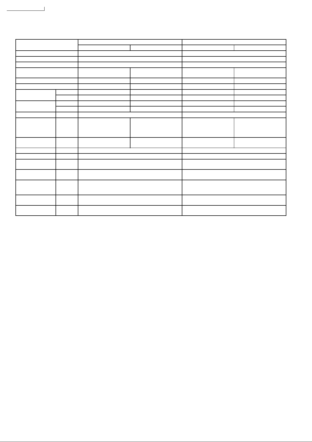
1 Product Specifications
Model CW-A90VE CW-A120VE
Cooling Heating Cooling Heating
Phase Single Single
Voltage 220 - 230 V 220 - 230 V
Frequency 50 Hz 50 Hz
Capacity 2.67 - 2.68 kW
9,100 - 9,140 Btu/h
Running Current 4.5 - 4.5 A 3.8 - 3.9 A 6.5 - 6.9 A 5.3 - 5.7 A
Input Power 980 - 1,03K W 820 - 880 W 1.36 - 1.48 kW 1.10 - 1.21 kW
EER W/W 2.72 - 2.60 W/W ------ 2.50 - 2.31 W/W ------
BTU/hW 9.3 - 8.9 ------ 8.5 - 7.9 ------
COP W/W ------ 3.11 - 2.92 W/W ------ 2.85 - 2.62 W/W
BTU/hW ------ 10.6 - 10.0 ------ 9.7 - 8.9
Starting Current 20 A 27 A
Noise Level Indoor (High / Low):
45 / 42 - 46 / 43 dB(A)
Outdoor (High / Low):
52 / 50 - 53 / 51 dB(A)
Power Noise Level Indoor: 58 dB(A)
Outdoor: 64 dB(A)
Fan Motor Output 32/36 W 46/51 W
Compressor Output 800 W 950 W
Moisture Removal 1.6 Ltr/h
3.4 Pint/h
Air Circulation 8.5 m3/min.
300 Ft
Dimensions Height: 14-25/32 inches (375 mm)
Width: 22-1/16 inches (560 mm)
Depth: 23-7/8 inches (606 mm)
Net Weight 35 kg
77 Ib
Refrigerant (R-22) 550 g
19.4 oz
Note: Specifications are subject to change without notice for further improvement.
2.55 - 2.57 kW
8,700 - 8,760 Btu/h
Indoor (High / Low):
44 / 41 - 45 / 42 dB(A)
Outdoor (High / Low):
54 / 52 - 55 / 53 dB(A)
Indoor: 56 dB(A)
Outdoor: 66 dB(A)
3
/min.
3.40 - 3.42 kW
11,600 - 11,700 Btu/h
Indoor (High / Low):
48 / 45 - 49 / 46 dB(A)
Outdoor (High / Low):
56 / 53 - 57 / 54 dB(A)
Indoor: 62 dB(A)
Outdoor: 68 dB(A)
2.0 Ltr/h
4.2 Pint/h
9.5 m3/min.
340 Ft
Height: 14-25/32 inches (375 mm)
Width: 22-1/16 inches (560 mm)
Depth: 23-7/8 inches (606 mm)
39 kg
86 Ib
650 g
22.9 oz
3.14 - 3.17 kW
10,700 - 10,800 Btu/h
Indoor (High / Low):
48 / 45 - 49 / 46 dB(A)
Outdoor (High / Low):
58 / 55 - 59 / 56 dB(A)
Indoor: 61 dB(A)
Outdoor: 70 dB(A)
3
/min.
2
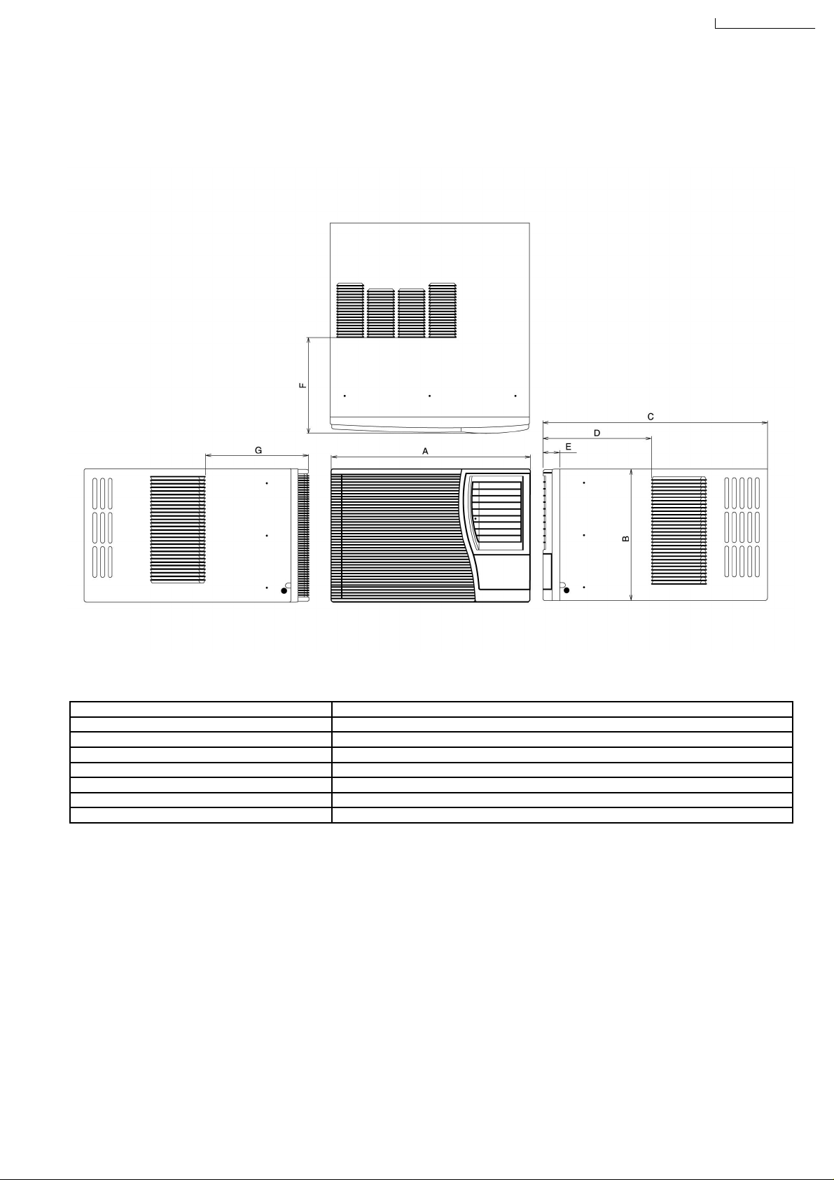
2 Dimensions
E
2.1. CW-A90VE, CW-A120VE
2.1.1. Top View, Front View & Side View
CW-A90VE / CW-A120V
2.2. Unit
Item Unit: Inch (mm)
A - Width 22-1/16” (560)
B - Height 14-25/32” (375)
C - Depth 23-7/8” (606)
D 11-9/16” (294)
E 1-13/16” (46)
F 11-3/32” (281.6)
G 1-13/32” (281.6)
3

CW-A90VE / CW-A120VE
3 Refrigeration Cycle Diagram
3.1. CW-A90VE & CW-A120VE
Note: Indoor temperature at 27°C (DB), 19°C (WB) and Outdoor at 35°C (DB), 24°C (WB) for Cooling & indoor temperature at
20°C (DB), 15.5°C (WB) and Outdoor at 7°C (DB), 6°C (WB) for Heating.
3.1.1. Cooling
CW-A90VE CW-A120VE
Item Pressure (MPa) Temperature (°C) Pressure (MPa) Temperature (°C)
A 1.81 ~ 2.01 67 ~ 82 2.09 ~ 2.28 67 ~ 82
B 1.76 ~ 1.96 38 ~ 48 2.04 ~ 2.23 37 ~ 47
C 0.51 ~ 0.57 7~12 0.53 ~ 0.59 8~13
D 0.48 ~ 0.54 10 ~ 17 0.50 ~ 0.56 8~15
3.1.2. Heating
CW-A90VE CW-A120VE
Item Pressure (MPa) Temperature (°C) Pressure (MPa) Temperature (°C)
A 0.40 ~0.46 0~5 0.37 ~ 0.43 -1 ~ 4
B 0.43 ~ 0.49 -1 ~ 4 0.40 ~ 0.46 0~5
C 1.52 ~ 1.72 31 ~ 41 1.51 ~ 1.71 31 ~ 41
D 1.57 ~ 1.76 42 ~ 52 1.56 ~ 1.75 41 ~ 51
4
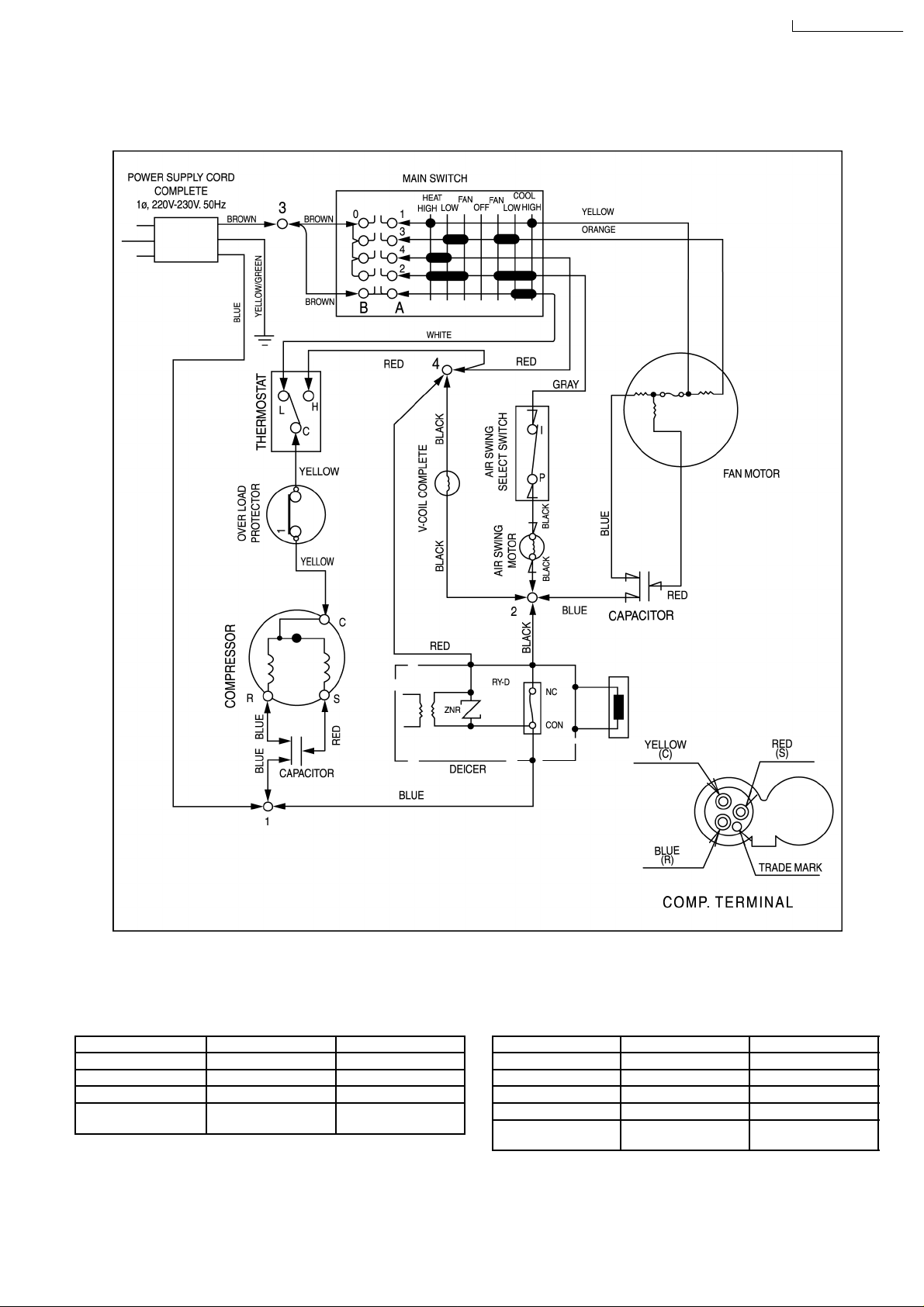
4 Wiring Diagram
E
4.1. CW-A90VE & CW-A120VE
CW-A90VE / CW-A120V
4.2. Resistance of Compressor
windings and the rated
Capacitor.
CW-A90VE CW-A120VE
Connection CWB092184 2KS206D5DA04
C-R 3.466Ω 2.293Ω
C-S 3.843Ω 3.245Ω
Capacitor DS371306CPNA
(30µF, 370VAC)
Note: Resistance at 20°C of Ambient Temperature.
DS371356CPNA
(35µF, 370VAC)
4.3. Resistance of Fan Motor
windings and the rated
Capacitor.
CW-A90VE CW-A120VE
Connection CWA951228 CWA921145
Blue - Yellow 205.8 Ω 84.1 Ω
Yellow - Orange 75.2 Ω 55.6 Ω
Red - Orange 170.0 Ω 118.3 Ω
Capacitor CWA31618
(2.0µF, 440VAC)
5
DS441305BPQH
(3µF, 440VAC)
CW-A90VE / CW-A120VE
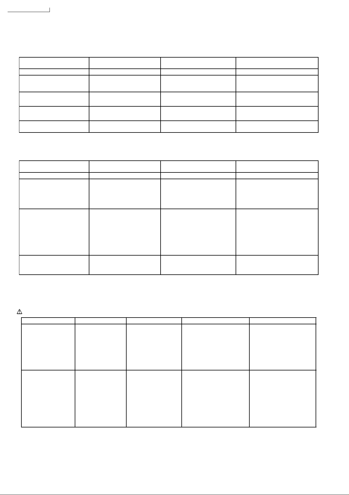
5 Air Conditioner Performance Evaluation
5.1. Cooling
Intake & Discharge Air
Temperature Difference
•
• 8°C and over (14.4°F) •
• •
•
• 8°C and over (14.4°F) •
• •
•
• Under 8°C (14.4°F) •
• •
•
• Under 8°C (14.4°F) •
• •
•
• Under 8°C (14.4°F) •
• •
Current Drain Determination Remedy
• As specified. •
• •
• Higher than specified. •
• •
• Higher than specified. •
• •
• Lower than specified. •
• •
• Higher than specified by
• •
50%.
• Nothing wrong. •
• •
• Nothing wrong, outdoor
• •
temperature is too high, heat
radiation is not efficient.
• Something is preventing heat
• •
radiation.
• Leakage of refrigerant or
• •
refrigerant system is blocked.
•
• Compressor defect or
• •
compressor capacitor defect.
Note: Room air humidity is relatively higher, the temperature difference will be smaller.
5.2. Heating
Intake & Discharge Air
Temperature Difference
•
• 14°C and over (25.2°F) •
• •
•
• 14°C and over (25.2°F) •
• •
•
• Under 14°C (25.2°F) •
• •
•
• Under 14°C (25.2°F) •
• •
Current Drain Determination Remedy
• As specified. •
• •
• Higher than specified. •
• •
• Lower than specified. •
• •
• Higher than specified by
• •
50%.
• Nothing wrong. •
• •
• Nothing wrong, outdoor
• •
temperature is high.
•
• Something is preventing heat
• •
radiation at indoor heat
exchanger.
• Nothing wrong, outdoor
• •
temperature is low.
•
• Something is preventing heat
• •
radiation at outdoor heat
exchanger.
•
• Leakage of refrigerant.
• •
•
• Refrigerant system is blocked.
• •
•
• Compressor defect.
• •
•
• Compressor capacitor defect
• •
• None.
• •
•
• Improve heat radiation.
• •
•
• Excessive amount of refrigerant.
• •
•
• Improve heat radiation.
• •
•
• Locate and repair leak.
• •
•
• Flush refrigeration cycle.
• •
•
• Replace the compressor or
• •
compressor capacitor.
• None.
• •
•
• None.
• •
•
• Clean air filter.
• •
•
• None.
• •
•
• Improve heat radiation at outdoor
• •
heat exchanger.
•
• Locate and repair leak.
• •
•
• Flush refrigeration cycle.
• •
•
• Replace the compressor.
• •
•
• Replace the compressor
• •
capacitor.
Note: Room air humidity is relatively higher, the temperature difference will be smaller.
6 Troubleshooting Guide
Warning: Disconnect unit from electrical power supply before making any electrical checks.
Trouble Check Result Cause Remedy
Fan Motor and
Compressor won’t run.
Fan Motor won’t run
(Compressor run).
•
• Supply Voltage
• •
•
• Fuse Box or Circuit
• •
Breaker.
•
• Power cord or
• •
Wiring Harness.
•
• Temperature
• •
Setting.
•
• Objects around
• •
Fan.
•
• RESISTANCE
• •
between Wires.
•
• Capacitor Fan
• •
Motor.
•
• Main Control
• •
Switch.
•
• Less than 10% by
• •
Rated.
•
• Open Contacts.
• •
•
• Pulled loose or
• •
Shorted.
•
• Higher than room
• •
temperature
•
• Locked Fan.
• •
•
• Shorted / Open
• •
circuit.
•
• OHM Meter doesn’t
• •
Deflect.
•
• No contacts at
• •
Position Shown.
•
• Temporary or Permanent?
• •
•
• Customer Restarted unit
• •
immediately without waiting
3 minutes.
•
• Fan Hitting Cowling
• •
•
• Foreign Materials.
• •
•
• Frozen Bearings.
• •
•
• Shorted or Burned out.
• •
•
• Capacitor Defect.
• •
•
• Main Control Switch defect.
• •
•
• Consult ELECTRICIAN, if
• •
permanent.
•
• WAIT FOR 3 MINUTES.
• •
•
• Repair Open Circuit.
• •
•
• Repair or Replace it.
• •
•
• Set it LOWER.
• •
•
• Adjust Fan position setting
• •
screw.
•
• Remove Foreign Materials.
• •
•
• Replace Fan Motor.
• •
•
• Replace Fan Motor.
• •
•
• Replace Capacitor Fan.
• •
•
• Replace Main Control
• •
Switch.
6
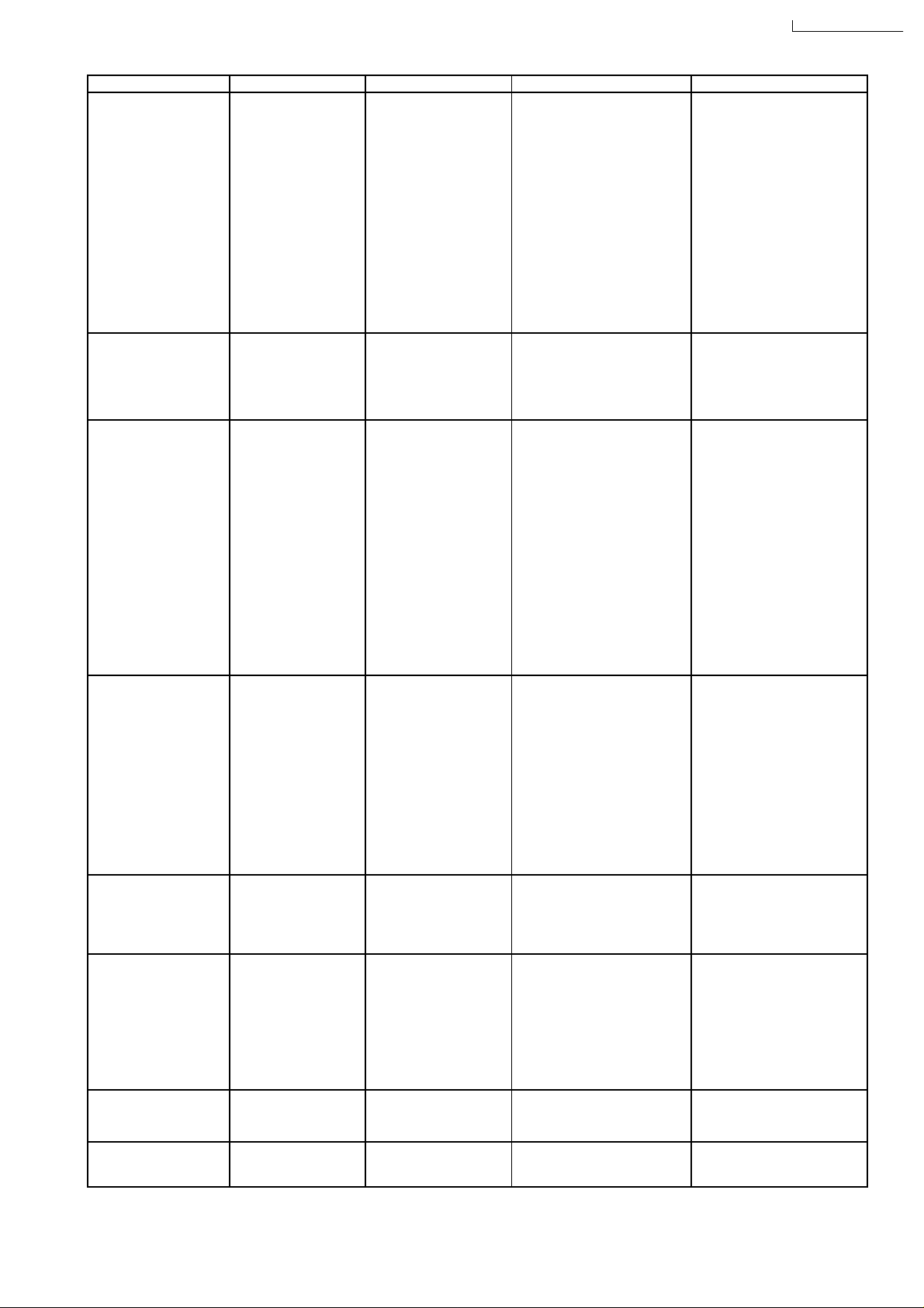
Trouble Check Result Cause Remedy
E
Compressor won’t run
(Fan run).
Air Swing won’t run.
Insufficient cooling or
heating.
Noise.
Water dripping inside
room.
Frozen Evaporator
No heating (Fan and
Compressor run).
Frozen Condenser
•
• Temperature
• •
setting.
•
• RESISTANCE
• •
between Terminal
and the
Compressor Body.
•
• RESISTANCE
• •
between Terminals.
•
• Overload Protector.
• •
•
• Capacitor
• •
Compressor.
•
• Thermostat.
• •
•
• Main Control
• •
Switch.
•
• Air Swing Switch.
• •
•
• Resistance
• •
between wires.
•
• Temperarute
• •
Setting.
•
• Ventilation door
• •
open.
•
• Air filter dirty.
• •
•
• Location of
• •
installation.
•
• Evaporator /
• •
Condenser Coil
obstructed.
•
• Unit capacity for
• •
the room too small.
•
• Temperature
• •
difference and
running current.
•
• Source of Noise •
• •
•
• Unit installation.
• •
•
• Drain Tray-
• •
Styrofoam pieces
blocking drain
channel.
•
• Temperature
• •
setting.
•
• Air filter /
• •
Evaporator.
•
• Temperature
• •
difference and
running current.
•
• Reversing valve
• •
coil.
•
• Reversing valve.
• •
•
• Outdoor ambient
• •
temperature
•
• Higher than room
• •
temp.
•
• Shorted.
• •
•
• Shorted.
• •
•
• Infinity between
• •
Terminals.
•
• OHM Meter doesn’t
• •
deflect.
•
• No click heard.
• •
•
• No contacts at
• •
Position Shown.
•
• OFF position.
• •
•
• No contact at
• •
position.
•
• OHM Meter doesn’t
• •
deflect.
•
• Higher than room
• •
temperature
•
• Open.
• •
•
• Clogged or dirty.
• •
•
• Sunlight hitting
• •
outdoor side.
•
• Obstacles.
• •
•
• Clogged or dirty.
• •
•
• Not satisfied.
• •
•
• REFER TO
• •
PERFORMANCE
EVALUATION.
• Vibration.
• •
•
• Intermittent Noise.
• •
•
• Tilted to inside room.
• •
•
• Clogged.
• •
•
• Set too low for
• •
ambient conditions.
•
• Clogged or Dirty.
• •
•
• REFER TO
• •
PERFORMANCE
EVALUATION.
•
• Infinity between coil.
• •
•
• Resistance between
• •
reversing valve coil.
•
• Heating operation at
• •
low outdoor ambient
temperature
•
• Winding Coil touched to
• •
the compressor shell.
•
• Rear Shorted or Burnt out.
• •
•
• Rear Shorted or Burnt out.
• •
•
• Overload Protector defect.
• •
•
• Capacitor defect.
• •
•
• Thermostat defect.
• •
•
• Main Control Switch defect.
• •
•
• Open circuit.
• •
•
• Shorted or open circuit.
• •
•
• Reduces capacity.
• •
•
• Restricted air circulation.
• •
•
• Restricted Heat Exchanger.
• •
•
• Restricted Heat Exchanger.
• •
•
• Restricted air circulation.
• •
•
• Leakage of refrigerant or
• •
refrigeration system is
blocked.
•
• Faulty installation.
• •
•
• Fan hitting objects.
• •
•
• Refrigerant tubing touching
• •
each other.
•
• Fan splashing Drain Water
• •
•
• Restricted run off.
• •
•
• Clogged or blocked.
• •
•
• Outdoor temperature low
• •
(Night time).
•
• Restricted air circulation.
• •
•
• Leakage of refrigerant or
• •
refrigeration system is
blocked.
•
• Outdoor ambient
• •
temperature is low.
CW-A90VE / CW-A120V
•
• Set it lower.
• •
•
• Replace Compressor.
• •
•
• Replace Compressor.
• •
•
• Replace Overload
• •
Protector.
•
• Replace Capacitor
• •
Compressor.
•
• Replace Thermostat.
• •
•
• Replace Main Control
• •
Switch.
•
• Set it ON.
• •
•
• Replace Air Swing Switch.
• •
•
• Replace Air Swing Motor.
• •
•
• Set it lower.
• •
•
• Close Ventilation door.
• •
•
• Clean or replace Air Filter.
• •
•
• Consider building an
• •
AWNING.
•
• Remove obstacles or
• •
reinstall unit.
•
• Clean the coils.
• •
•
• Replace the unit with
• •
bigger one.
•
• Locate repair leak.
• •
•
• Flush refrigeration cycle.
• •
•
• Reinstall unit or Reinforce
• •
the installation.
•
• Adjust Fan position or
• •
remove foreign materials.
•
• About 1/2” Clearance
• •
needed.
•
• Remove drain plug and
• •
mount a drain pan to
remove the water.
•
• Set the Drain outlet
• •
downward, so that the
Drain water can run off
•
• Tilt unit to outside slightly.
• •
•
• Remove the foreign
• •
materials.
•
• Set the Main Control Knob
• •
to Fan to melt ice and set
the Temperature control to
higher temperature.
•
• Clean Air filter /
• •
Evaporator.
•
• Locate and repair leak.
• •
•
• Flush refrigeration cycle.
• •
•
• Replace reversing valve
• •
coil.
•
• Replace reversing valve.
• •
•
• Set Main Control Switch to
• •
Fan to melt ice.
7
 Loading...