

Page 1
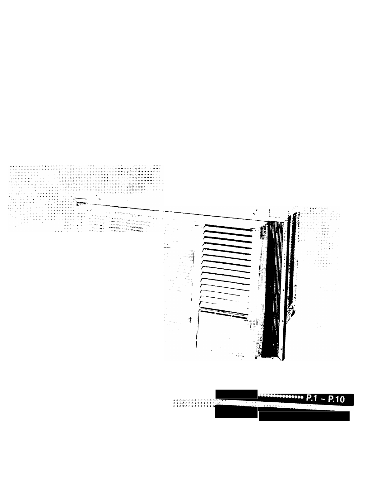
Operating
Instructions
Room Air Conditioner
Model; CW-1406BU
m::
Panasonic.
A tt- '!■ 0 n ^ - >•'' i'
■'« «■ tí' <a- 5* >1- Í. ft
♦ . ir
*•***-»♦•♦•• C C C ^ '■' 0 Í? C C o O O' ^ ■■ ■
» A » **--a ■*••««•••>' '■ OOOOOOO-'" - -
»■»«»#**••■»*«•«>- ■.- oocroooc
w o o o o o O. o
■ « © C Í* A
ENGLISH
español
.
....................
P.11 ~ P.19
F561157
Page 2

IMPORTANT SAFEGUARDS
CONTENTS
The following are important instructions to be
observed to prevent malfunctions or serious
problems with your air conditioner.
1 Install the air conditioner by following the installation
instructions enclosed with the product
2 Do not modify any parts of this product
3 Do not operate the unit without an air filter
4 Do not put sticks, rods, etc , into any parts of the unit
5 Do not obstruct the air intake of the evaporator with
a curtain or window blind, as it may result in
insufficient cooling power and abnormal operation
6 Operate your air conditioner from a stable 115 Volt
AC power supply
7 Plug into a separate 15 amp rated grounded outlet
only
8 Use of Extension Cords
Extension cords of any kind should not be used If
there IS no alternative, the cord should be a UL listed
3-wtre grounding type, rated 125 volt with a minimum
current carrying rating of 15 amps-number 14 or
heavier wire
9 Use a 15 amp time delay fuse or a circuit breaker
10 Do not install the unit close to any places where
inflammable gas, fumes or soot may be generated
11 Do not unplug the unit while it is operating Turn the
Mam Switch to “OFF” and then unplug
• Product Component Identification
• Air Conditioner Operation
• Care And Maintenance
• Helpful Reminders
• Before Calling For Service
• Product Specifications
CUSTOMER'S RECORD
Record the model and serial number from the model
label located on the side of cabinet
This information may be helpful in correspondence or
service calls concerning your air conditioner
Model Number
Serial Number
Dealer Name
2
3~4
5-6
7
8
9
SAVE THESE INSTRUCTIONS
1995 Matsushita Electrical Co, Ltd All Rights Reserved
Purchase Date
Page 3
Product Component Identification
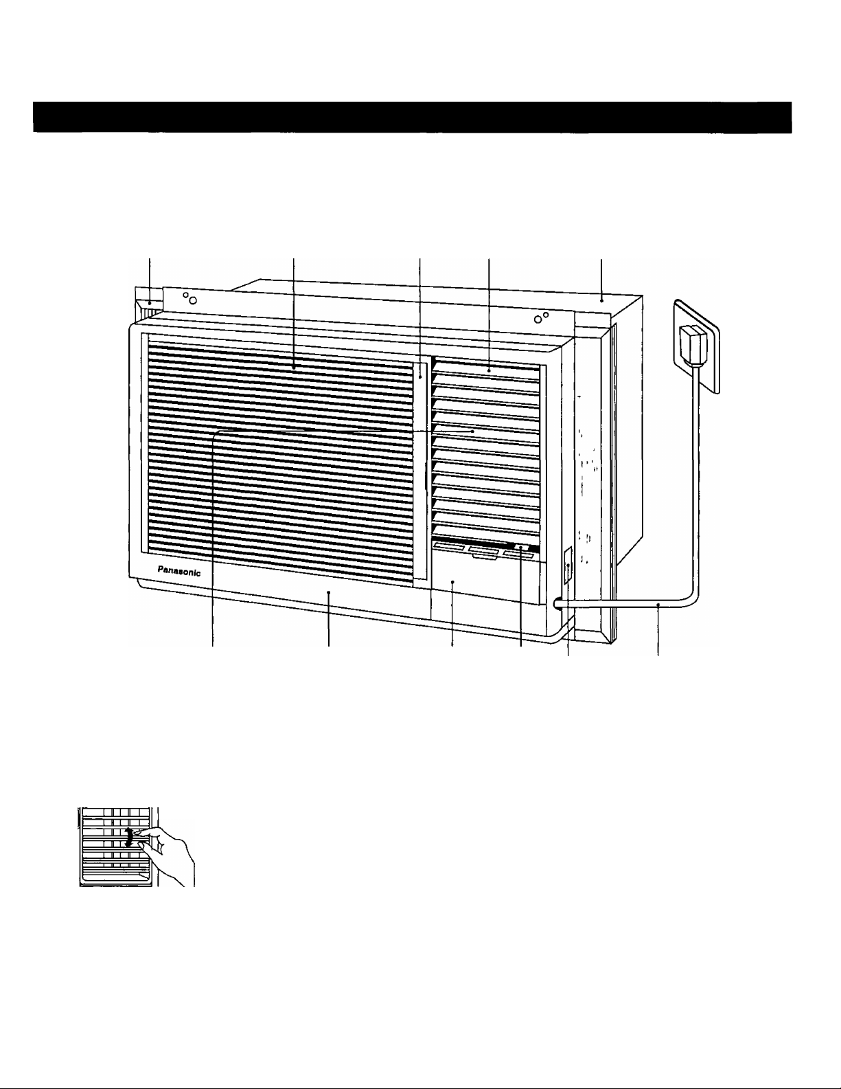
Expandable Panel Air Intake Grille Air Filter Air Outlet Louvers Cabinet
Vertical Airflow Direction Vane
(Airflow direction adjustment Up-and-Down)
Vertical airflow direction
adjustment louvers
r
The vertical airflow direction vane
IS controlled by positioning the
vane to discharge the air upwards,
downwards or straight out
For better cooling efficiency and
air circulation turn the louver
upwards
Front Grille
Control Panel Cover
(Behind IS Control Panel)
^ r
Ventiiation Lever
CLOSE-^VENT^ OPEN
Model/Serial
Number Label
When the slide lever is at the
OPEN position, the vent door
opens to allow air, smoke or odors
to be expelled from the room
CLOSE position, the vent door is
closed and the air inside the room
IS circulated and conditioned
Power Supply Cord
Page 4
Air Conditioner Operation
Over than 14 4°F
(8°C) difference
More than 14 4"F
(8®C) of tempera
ture difference
between intake
and outlet air is
normal after 15
minutes of opera
tion started
Page 5
1
2
3
Power Supply
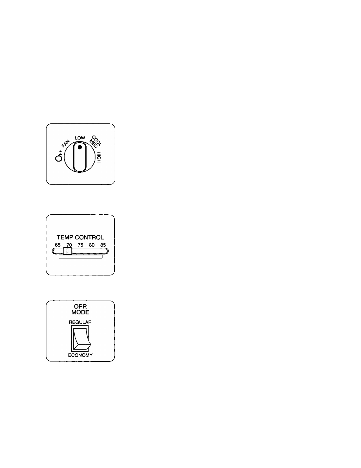
Set the Main Control Knob to the OFF position; confirm that the Power Supply Cord is connected to a proper AC outlet.
<115V, 60Hz>
Main Control Knob
Set Main Control Knob to desired position :
OFF - Stops all operations.
FAN - Fan only operation without cooling.
LOW COOL - Air cooling operation at tow fan speed.
MED COOL - Air cooling operation at medium fan speed.
HIGH COOL - Air cooling operation at high fan speed.
Note : To resume cooling operation, wait 3-5 minutes before restart.
Temp Control Knob
Select the desired temperature.
Lower number side - More cool.
Higher number side - Less cool.
4
Note ; Temp Control number indications are for reference use only and do not
represent actual room temperatures.
Operation Mode Switch
REGULAR - The temp, control automatically controls cooling, but the fan runs
continuously whenever the air conditioner is in operation.
ECONOMY - The temp, control automatically controls cooling, but when the
room temperature reaches the temp, control preset point, both the
fan and compressor turn off. When the temp, control requires the
cooling operation to start again, both the fan and compressor turn
back on together.
Note : For fan only operation, Operation Mode Switch must be in “REGULAR”
position.
The fan will not run with the Main Control Knob set to FAN while the
operation mode switch is set to “ECONOMY”.
Caution : If the unit is turned OFF and immediately on again, an automatic protection device will prevent restart of
the compressor for approximately 3 minutes.
This is normal, leave the switch ON and operation will resume automatically when the protection delay
is completed.
Page 6
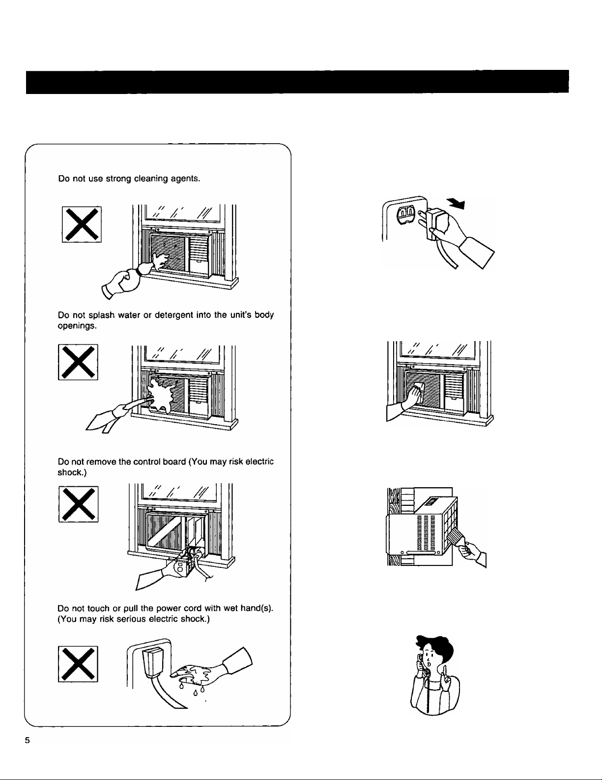
Care And Maintenance
Precautions for cleaning
Air conditioner body
1. Unplug the power cord.
2. Wipe the front grille with a cloth dampened in soapand-water solution or lukewarm-water.
3. Rid the rear air inlets of dust by using a paint brush,
or the like.
4. If the unit is badly soiled, heat transfer is less efficient,
contact your nearest Panasonic servicenter.
Page 7
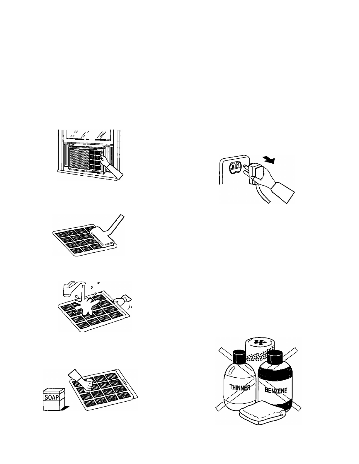
Air filter every 2 weeks
Unplug the power cord
r
1 To remove the air filter, pull its removal tab to
the right
Vacuum-clean its front (or wipe it clean with a
cloth)
3 Wash rear side with water
When not using the air conditioner for a long time
For air conditioners with a power cord, stop operation
and pull out the power cord
Caution:
Wipe off dirt with a soft, dry cloth (use a vacuum cleaner
to remove dust from the air inlet)
Use a cloth and water less than 104*F to remove stubborn
dirt (the cloth should be well-wrung)
Do not use the following cleansers as they may cause
the paint to peel and lead to malfunctions Benzene,
thinner, scouring powder, chemical soaked cloths, etc
If the air filter is badly soiled, wash it with mild
household detergent, pat dry and place it
back in position
J
6
Page 8
Helpful Reminders
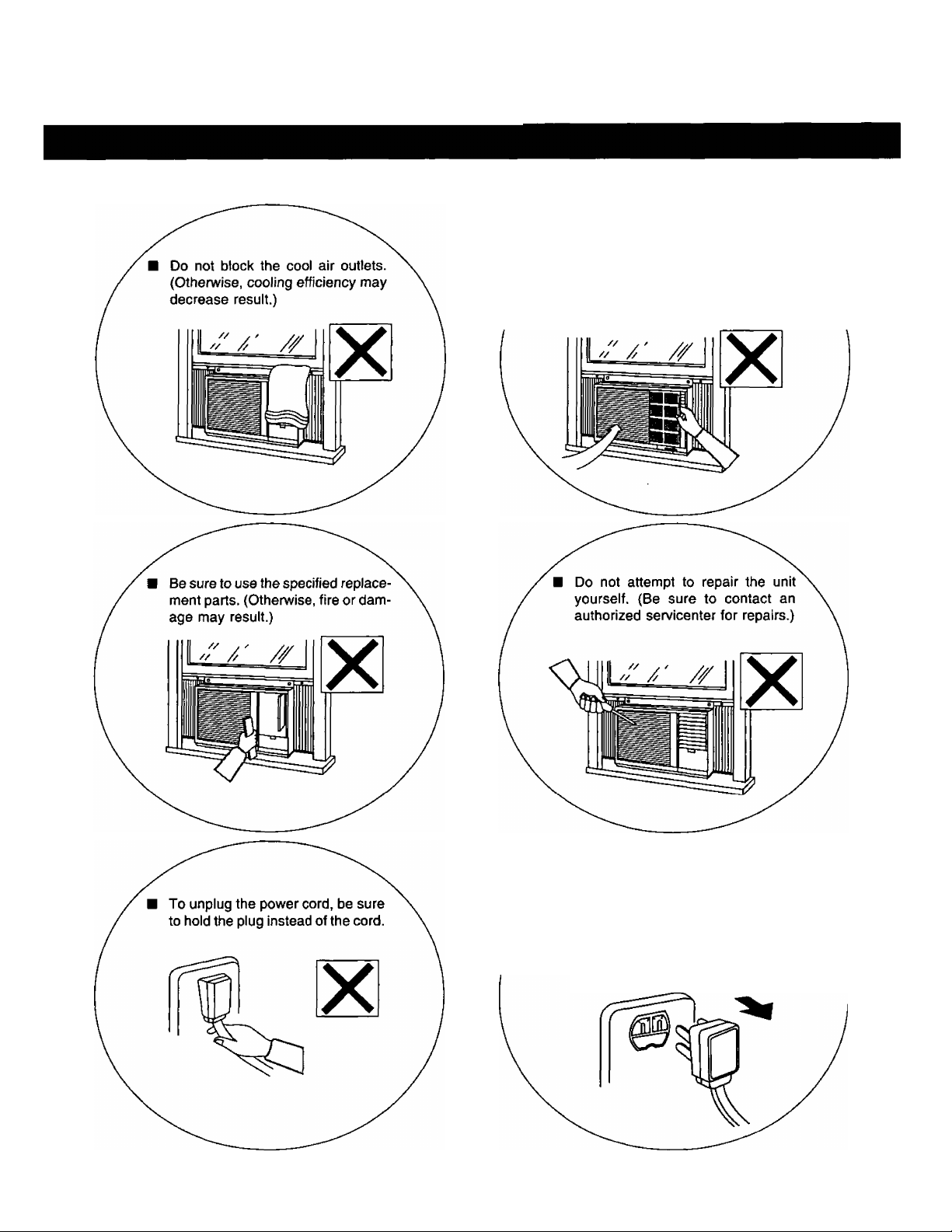
Do not operate the unit without in
serting the air filter. (Dust may clog
the evaporator or unit failure may
result.)
Be sure to turn off the power or un
plug the power cord in case of power
failure. (After the power is restarted,
wait for at least 3 minutes before
restarting the unit.)
7
Page 9
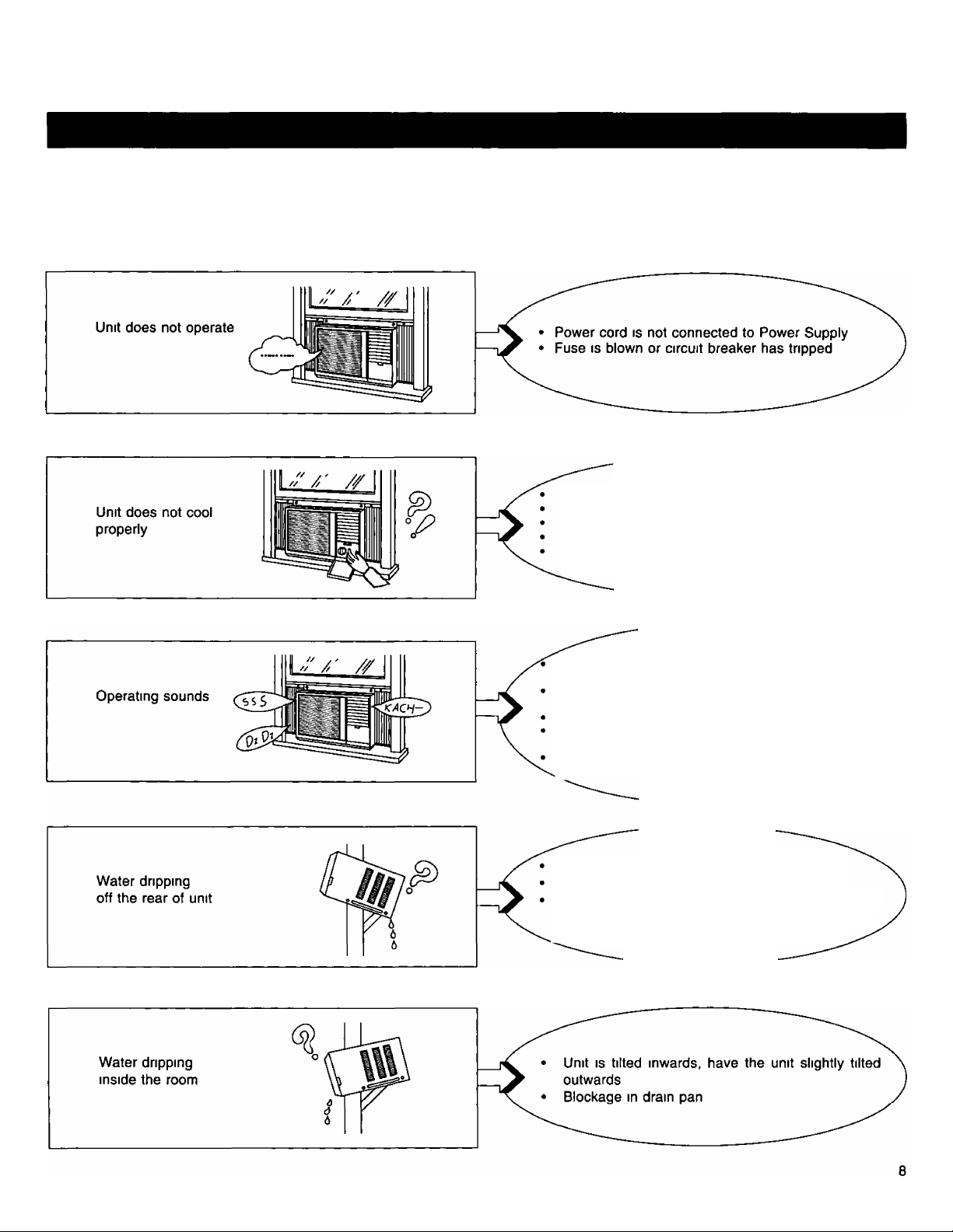
Before Calling For Service
Problem symptom
Possible cause and remedy
Temp Control (S set at lower number levels
Air filter requires cleaning
Room size is too large for capacity of unit
Ventilation lever is set OPEN
The air circulation is impeded by drapes, furniture,
etc , or by an improper louver setting
Normal Operating Sound
A soft clicking sound when compressor turns of^
and off
Refrigerant circulating sound when compressor is
turned on
Low humming sound when the unit is in operation
Water splashing sound, condensation slings onto
condenser coil
For noise heard other than mentioned above,
contact your nearest servicenter
High humidity condition (Normal)
Condensate water is overflowing
Mount the dram pan to the unit Dram pan can be
obtained from the nearest servicenter
(Dram pan part number CWH40077)
Page 10
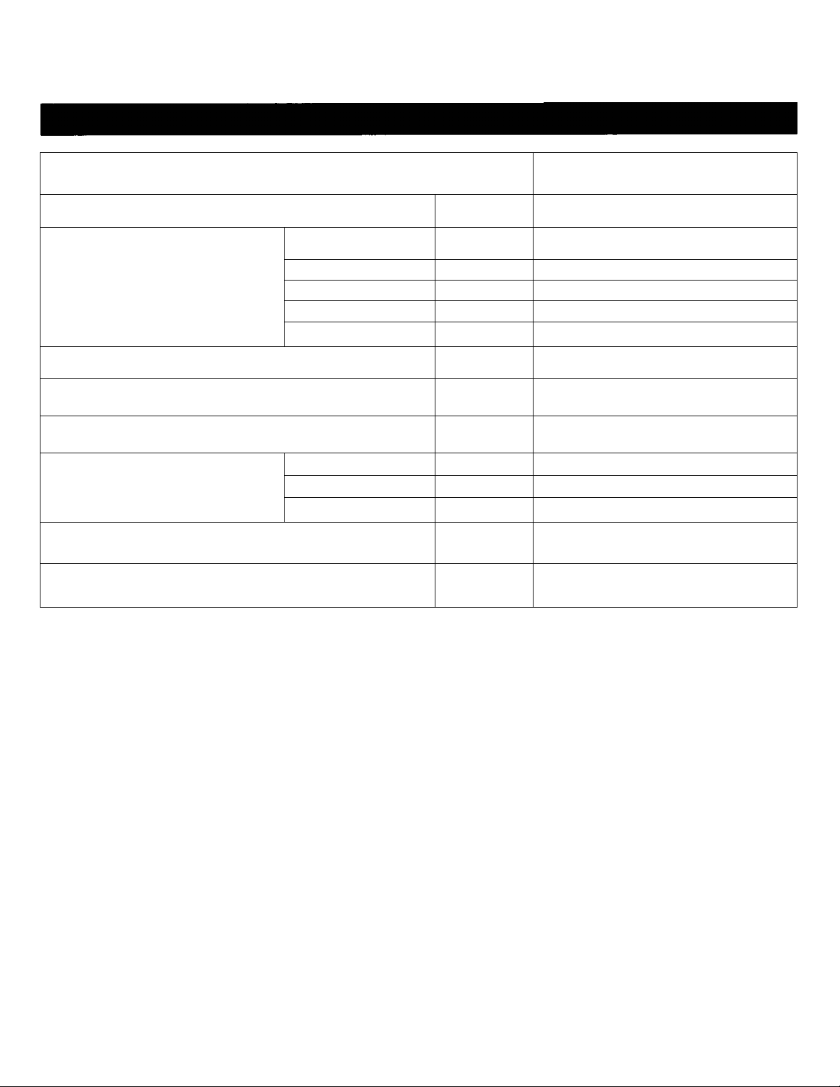
Product Specifications
MODEL
COOLING CAPACITY
ELECTRICAL
RATING
EER
MOISTURE REMOVAL
ROOM AIR CIRCULATION
DIMENSIONS
NET WEIGHT
CW-1406BU
Btu/h
Phase
Cycle
Voltage
Running Current
Power Input Watts
Height Inches 16-7/8
Width Inches
Depth Inches
Hz 60
V 115
Amps.
Btu/Watt«h 9.5
Pints/hr
Cf/min 390
lbs
13,500
Single
12.0
1,420
3.4
26
25-7/32
126
GROSS WEIGHT
"Specifications are subject to change without notice for further improvement.
if the trouble persists after you have checked all of these, call your authorized Panasonic
dealer or servicenter.
Service information can be obtained 24 hours/day by calling 1-800-545-2672.
lbs 143
Page 11

ENGLISH
I
Page 12

DETALLES DE
SEGURIDAD IMPORTANTES
Las siguientes instrucciones son importantes de
tener en cuenta para evitar malfuncíonamientos o
problemas senos con su acondicionador de aire.
1 Instale el acondicionador de aire siguiendo las
instrucciones de instalación que vienen con este
producto
2 No modifique ninguna de las piezas de este producto
3 No haga funcionar este aparato sin el filtro de aire
4 No introduzca palillos, lápices, etc dentro de este
aparato
5 No tape la toma de aire del evaporador con una
cortina o similar, pues puede resultar en insuficiente
fuerza de enfriamiento y funcionamiento anormal
6 Haga funcionar su acondicionador de aire desde
una fuente de alimentación de CA de 115 voltios
7 Enchúfelo sólo en un tomacorriente separado de 15
amp con conexión a tierra
B Uso de cables de extensión
No se deben usar cables de extensión de ningún
tipo 5i no existiera otra posibilidad, debería ser un
cable de 3 alambres con conexión a tierra de tipo
UL, de 125 voltios con un amperaje mínimo de 15
amp, de alambre número 14 o mayor
9 Use un fusible de retardo de 15 amp o un ruptor de
circuito
10 No instale el aparato cerca de un lugar donde haya
gases inflamables, emanaciones de humo u hollín
11 No desenchufe el aparato mientras está funcionando
Gire la perilla de control principal a la posición “OFP
y luego desenchúfelo
CONTENIDO
Identificación De Los Componentes 12
Funcionamiento Del Acondicionador De Aire 13-14
Cuidados Y Mantenimiento
Consejos Útiles
Antes De Llamar Al Técnico
Especificaciones Del Producto
15 - 16
17
IB
19
REGISTRO DEL CLIENTE
Anote el modelo y número de sene que se encuentra
en la etiqueta de modelo ubicada en la parte lateral del
aparato
Esta información puede ser útil al escribir o llamar al
técnico de servicio del acondicionador de aire
Número de modelo
Número de sene
Nombre del comercio
GUARDE ESTAS INSTRUCCIONES
© 1995 Malsushila Electrical Ce , Ltd Derechos Reservados
11
Fecha de compra
Page 13
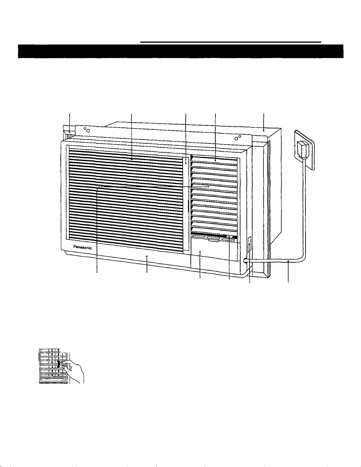
Identificación De Los Componentes
Parrilla Expandible Rejilla de entrada de aire Filtro de aire salida del Aire Caja
Persianas para la
Rejilla
delantera
Cubierta del Tablero de
Parrilla Control
(Detrás esta el Tablero de
Control)
Paleta de Dimección Vertical de la Corriente de Aire.
(Ajuste de la dirección de la corriente de aire hacia arriba y
hacia abajo)
Persianas para el ajuste
vertical de la dirección de
la corriente de aire.
Xq
La Paleta de Dirección Vertical
de la Corriente de aire se controla
colocando la paleta para que
descargue el aire hacia arriba,
hacia abajo o de frente.
Para mayor eficiencia del
enfriamiento y circulación de aire
poner las paletas hacia arriba.
Modelo/Número
de Serie
Palanca De Ventilación
Cuando la palanca se encuentra
deslizada en la:
Posición OPEN, la puerta del
respiradero se abre para permitir
CLOSED VENT^ OPEN
que el aire, humo u olor sean
expulsados de la habitación.
Posición CLOSE, la puerta del
respiradero está cerrada y el aire
dentro de la habitación circula y
es condicionado.
Cable de alimentación
de corriente
12
Page 14
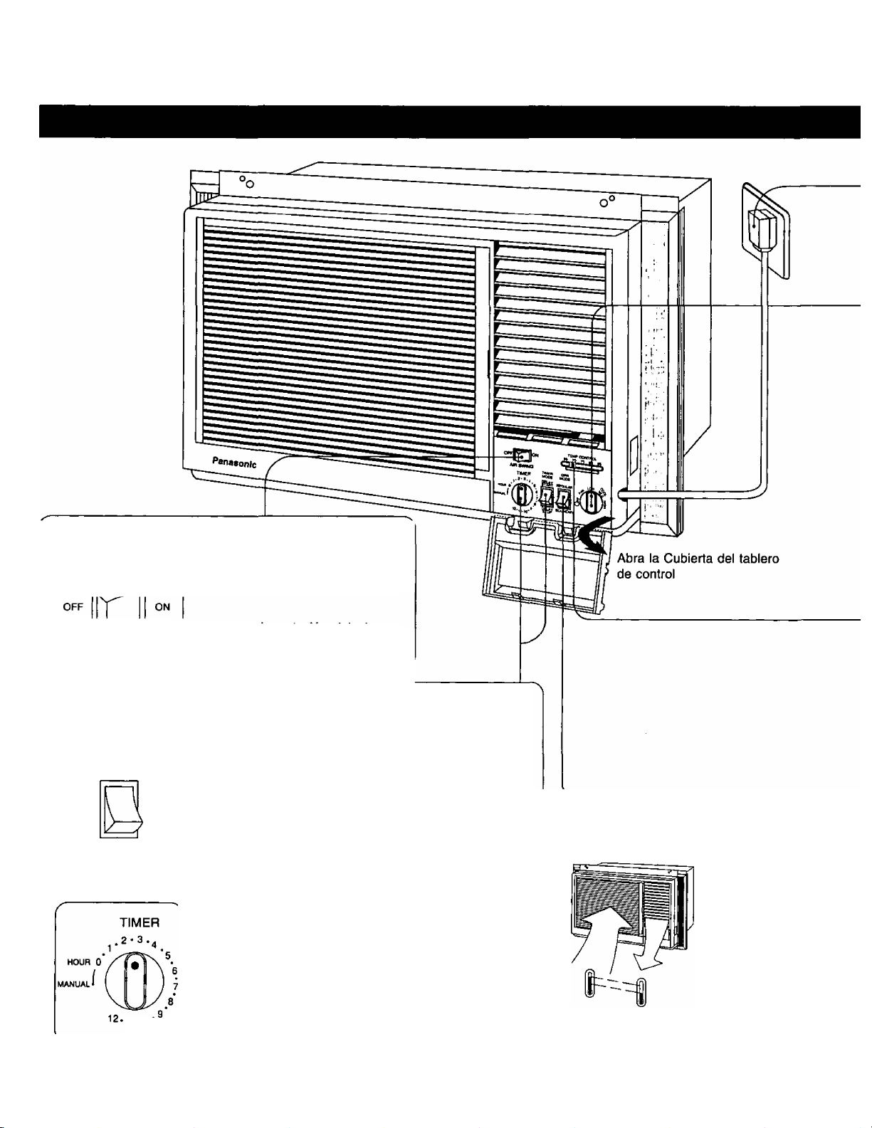
Funcionamiento Del Acondicionador De Aire
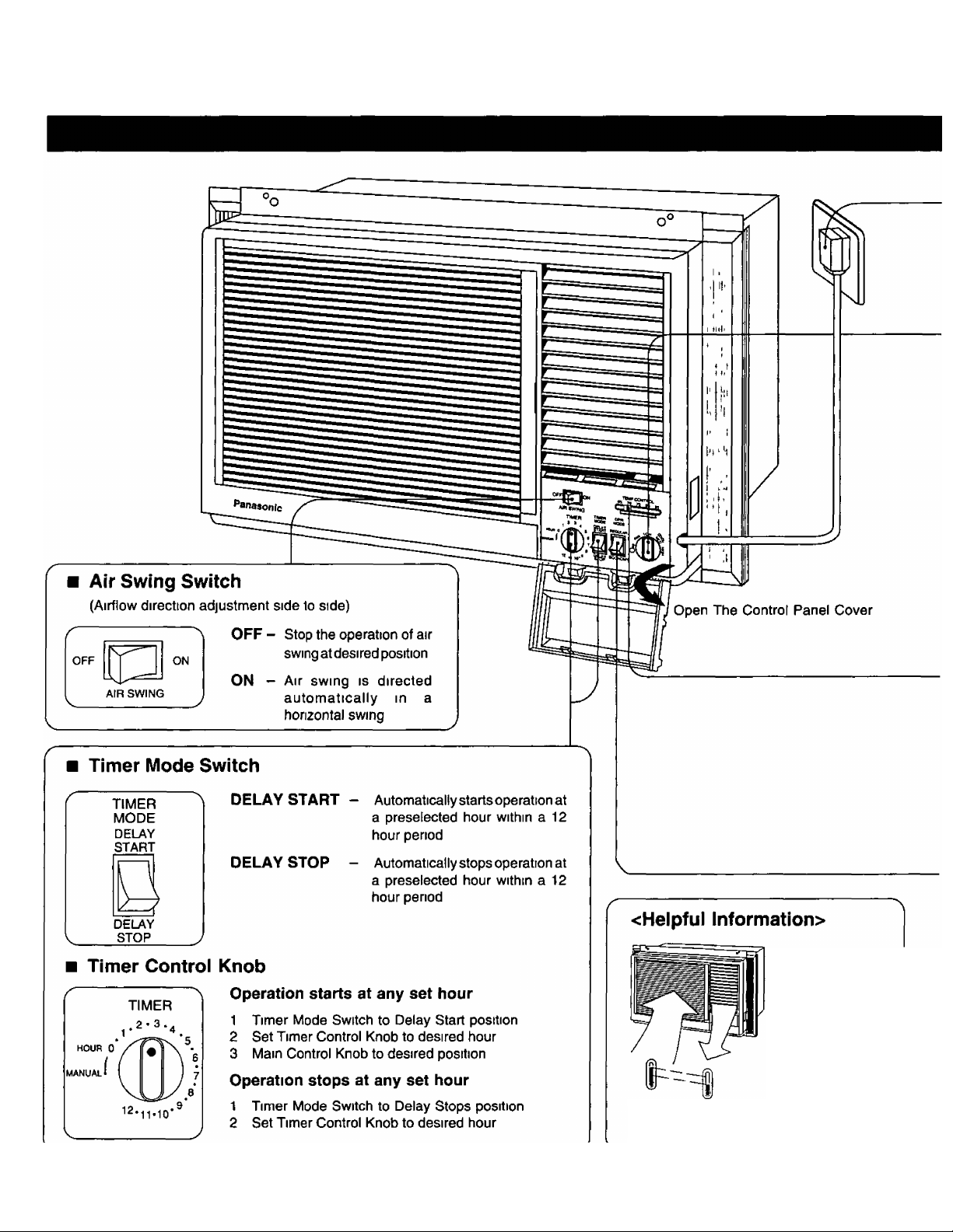
Interruptor de Rotación del Aire
(Ajuste de dirección de flujo del aire de lado a lado)
AIR SWING
OFF -
(Apagado)
ON -
(Encendido)
Detiene la función de
rotación del aire en una
posición deseada.
La rotación del aire es
dirigida automáticamente
en una rotación horizontal.
Interruptor del Modo de Temporizador
TIMER
MODE
DELAY
START
DELAY
STOP
DELAY START
(Comienzo
Demorado)
DELAY STOP
(Parada
Demorado)
El acondicionador de aire
comenzará a funcionar
automáticamente a la hora
preseleccionada dentro de un
período de 12 horas.
El acondicionador de aire dejará
de funcionar automáticamente
a la hora preseleccionada dentro
de un período de 12 horas.
Perilla de Control del Temporizador
El funcionamiento comenzará a la hora deseada.
1. Coloque el Interruptor del Modo de Temporizador en
la posición DELAY START.
2.
Ajuste la Perilla de Control del Temporizador a la hora
deseada.
Coloque la perilla de control principal en la posición
3.
deseada.
El funcionamiento parará a ia hora deseada.
1. Coloque el Interruptor del Modo de Temporizador en
11*10
la posición DELAY STOP.
2. Ajuste la Perilla de Control del Temporizador a la hora
deseada.
<lnformación Util>
Sobre una diferencia
de 14,4°F (8°C)
Más de 14,4“F
(S-’C) de
diferencia en la
temperatura
entre la en trada
y salida del
aire es normal
luego de haber
transcurrido 15
minutos de
funcionamiento,
13
Page 15
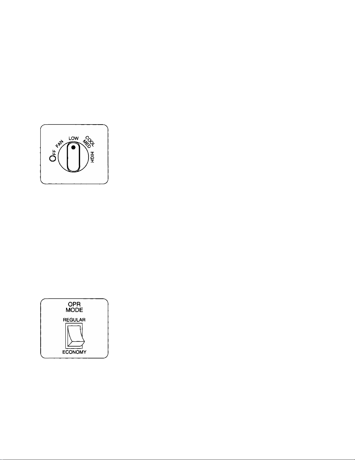
1
Suministro de eléctricidad
Ajuste la Perilla del Control Principal en la posición OFF, asegure que el cable de alimentación sea conectado a la toma
de pared adecuada <115V, 60Hz>
Perilia de Controi Principai
Ajuste la Perilla de Control Principal en la posición deseada
2
3
4
OFF - Detiene toda la operación
FAN - Función de abanico solamente sin enfnamiento
LOW COOL - Función de enfriamiento del aire a velocidad baja de abanico
MED COOL - Función de enfnamientodel aire a velocidad media de abanico
HIGH COOL - Función de enfriamiento del aire a velocidad alta de abanico
Nota : Para reiniciar la función de enfriamiento, espere 3-5 minutos antes de
Perilla de Control de Temperatura
Para seleccionar la temperature deseada
Números menores - Más frío
TEMP CONTROL
65 70 75 80 85
Interruptor del Modo de Función
Números mayores - Menos frío
Nota Los números en el control de temperatura son sólo para referencia y no
REGULAR - El controlador de la temperatura controla automáticamente el
(Regular) enfriamiento pero el ventilador funciona continuamente siempre
volverlo a hacer funcionar
representan la temperatura real de la habitación
que el acondicionador de aire esté operando
ECONOMY - El controlador de temperatura controla automáticamente el
(Economía) enfriamiento pero cuando la temperatura de la habitación alcance
el punto de preajustado, ambos, el ventilador y el compresor se
apagarán Cuando el controlador de temperatura requiere que se
reinicie el enfriamiento, ambos, el ventilador y el compresor
entrarán en funciónamiento juntos
Nota : Para la función de abanico solamente, el Interruptor de Modo de
Función debe estar en la posición “REGULAR"
El abanico no funcionará con la Penila de Manejo Pnncipal colocada en FAN
mientrás el interruptor de modo de función se encuentra en posición de
“ECONOMr
Cuidado : Si el aparato se apague e inmediatamente se vuelve a encender, un dispositivo de protección automático
evitara que el compresor vuelva a funcionar por aproximadamente 3 minutos
Esto es normal, deje el interruptor en la posición “ON" y el funcionamiento se reanudará automáticamente
cuando el retraso protección sea completado
14
Page 16
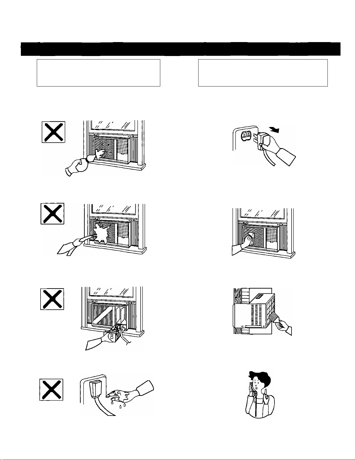
Cuidados Y Mantenimiento
Precauciones Cuerpo del
para la limpieza
No utilice agentes de limpieza que sean fuertes
No salpique agua □ detergente dentro de las aberturas
del cuerpo del aparato
acondicionador del aire
r
1 Desconecte el cable de alimentación
2 Limpie la rejilla frontal del acondicionador de aire con
Un trapo humedecido en agua con jabón o con agua
libia solamente
V,
15
No remueva el tablero de los conlroles (se arriesgaría
a un choque eléctrico)
No toque o hale el cable da alimentacién con las
manos mojadas (Se arriesgaría a recibir un fuerte
choque eléctrica)
3 Libre las entradas de aire posteriores de polvo usando
Una brocha para pintar □ algo similar
4 Si la unidad se encuenta bastante deteriorada, la
transferencia de calor es mucho menós eficiente,
contacte a su centro de servicio Panasonic más
cercano
Page 17
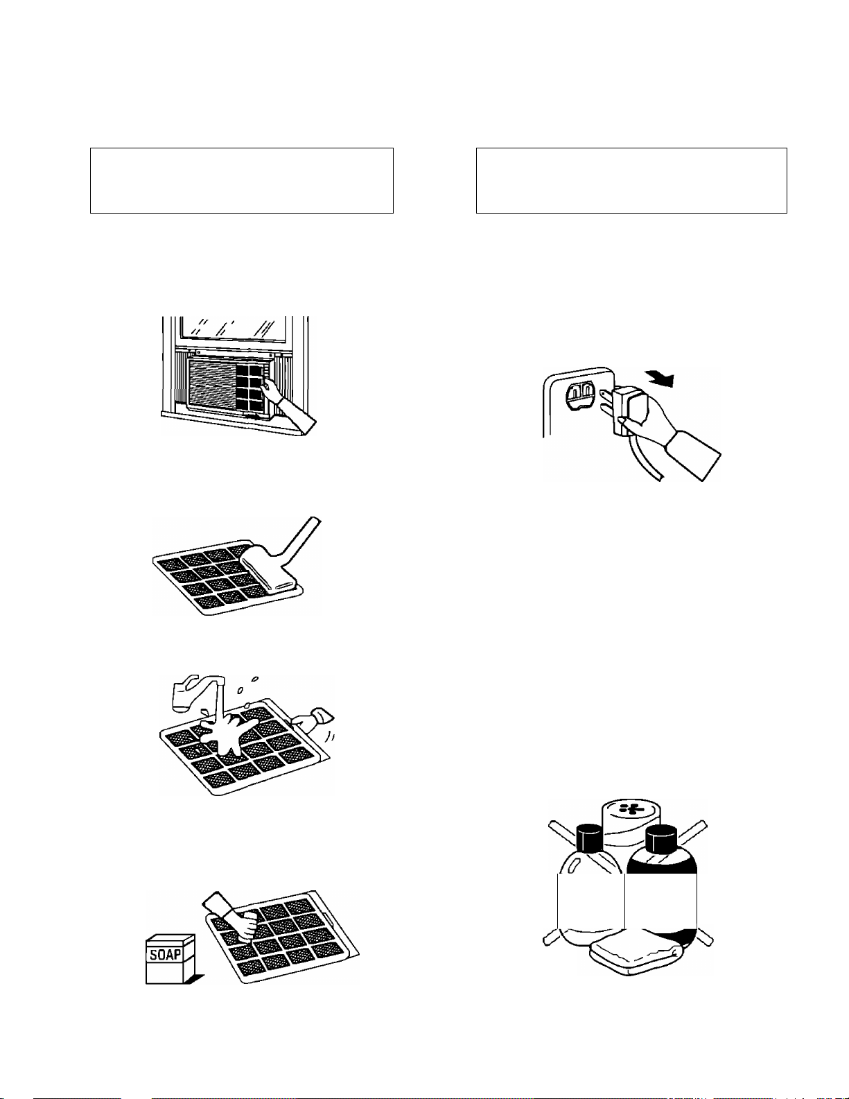
El filtro de aire cada
Desconecte el
dos semanas
1 Рага гвтпуег в1 Filtra da aire, tire de la
lengüeta hacia la derecha
2 Limpie con una aspiradora su parle Frantal (□
limpíelo con un paño)
cable de alimentación
л г
Al no ser utilizado el acondicionador de aire por un largo
periodo
Para acondicionadores de aire con un cable de energía,
detenga el Funcionamiento y tire del cable de alimenta
ción
b
I
3 Lave con agua la parte trasera
Si el filro de aire estuviera domasiado sucio,
lávelo con detergente suave casero, golpéelo
hasta secar y colóquelo nuevamente
en posición
PRECAUCION:
Limpie la suciedad con un paño limpio y seco (use una
aspiradora para retirar el polvo de la entrada de aire)
Use un paño y agua a menos de 1ü4''F para remover
suciedad más diFicil (el paño deberá estar bien exprimido)
No haga uso de los siguientes limpiadores ya que pueden
causar desprendimientos de la pintura y llegar a provocar
un mal Funcionamiento Bencina, tfner, polvo de fregar,
paños empapadas en productos químicos, etc
TINEB^^
y V.
16
Page 18
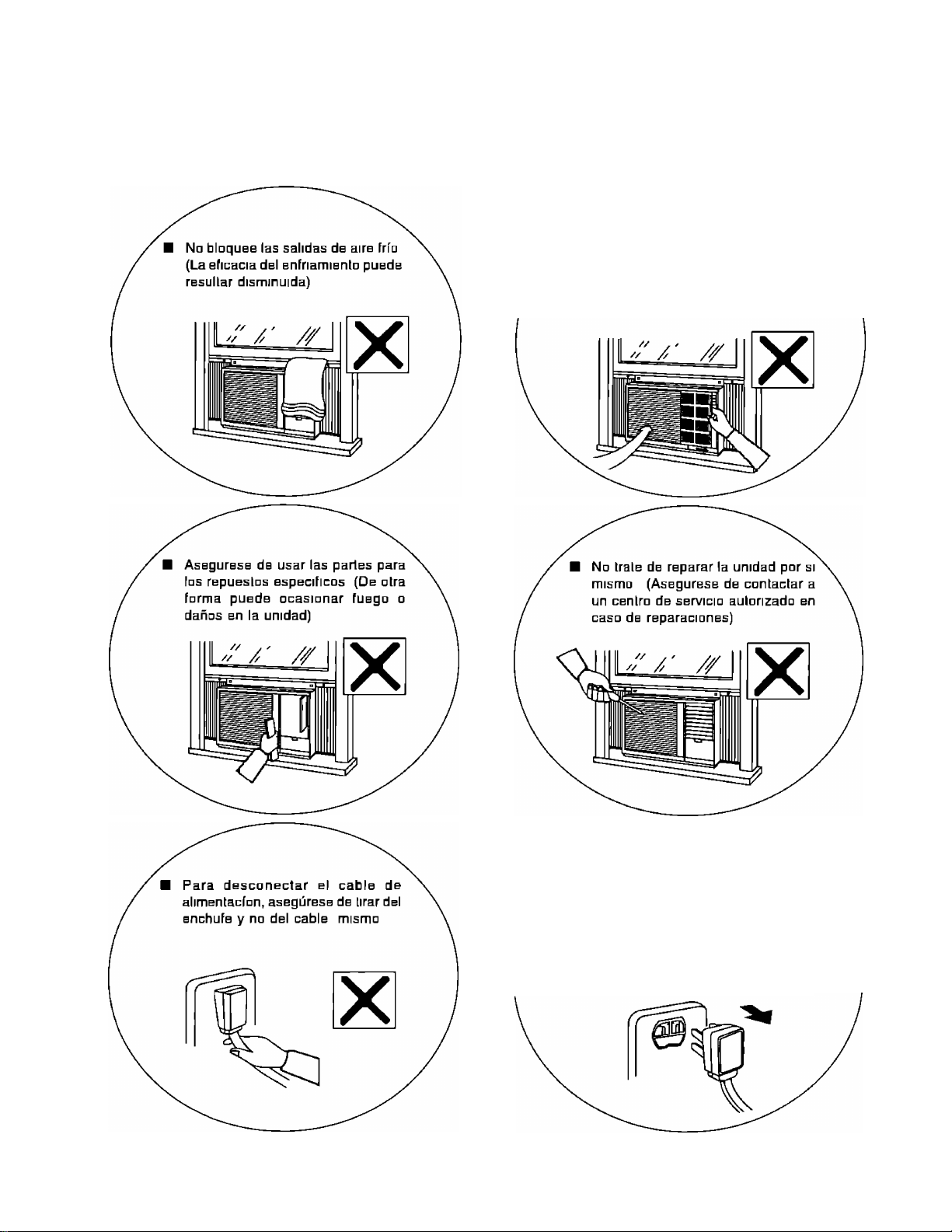
Consejos Útiles
Na panga en función la unidad sin
haber instalado el filtro de aire (El
polvo puede obstruir el evaporador
□ causar une falla en la unidad)
Asegúrese de apagar o de desco
nectar el cable de alimentación en
caso de un corle de corrienle
(Después de que regrese la
comente, espere por lo menos 3
minutos antes de poner en función
la unidad)
17
Page 19
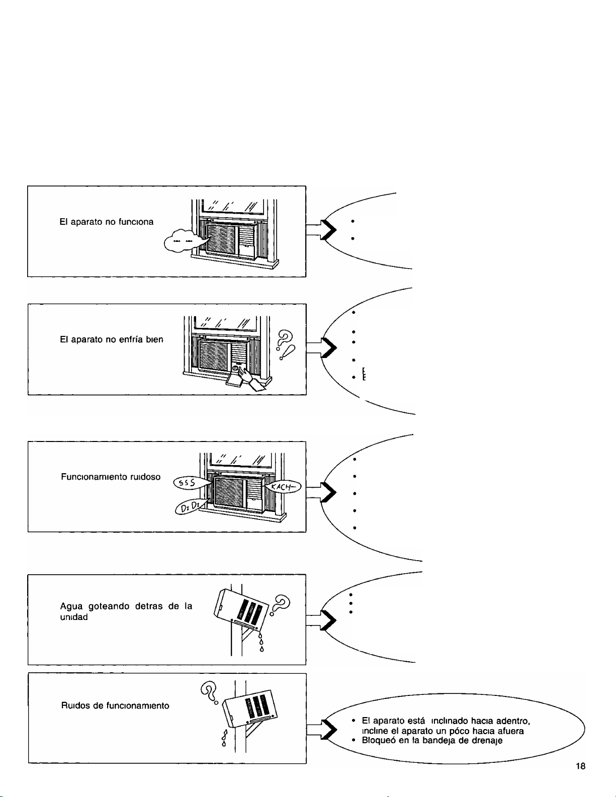
Antes De Llamar Al Técnico
Sintomas del problema
Posible causa y remedio
El cable de alimentación no está enchufado al
enchufle
El fusible está quemado o el ruptor de circuito se
ha zafado
El Control de Temperatura está ajustada en un
numero bajo
El filtro de aire requiere limpieza
El tamaño de la habitación es muy grande para
la capacidad de la unidad
La palanca de ventilación se encuentra en la
^josición "OREN"
:l aire no puede circular bien porque cortinas,
muebles u otros se lo impiden, o debido a un
ajuste inadecuado de las paletas
Sonidos normales del funcionamiento
Un suave "clic" cuando el compresor se
enciende o apaga
El sonido de) refrigerante circulando cuando
el compresor se enciende
Un murmullo suave cuando el aparato está
funcionando
Ruido de chapoteo de agua, condensasión se
suspende en el condensador
S
i escucha ruidos diferentes a los anteriores,
consulte al centro de servicio más cercano
Condición de humedad alta (Normal)
El agua condensaba se está desbordando
Si lo prefiere, instale la bandeja de drenaje La
bandeja de drenaje puade obtenerse en el centro
de servicio más cercano
( La bandeja de drenaje pieza numero
CWH40077)
Page 20
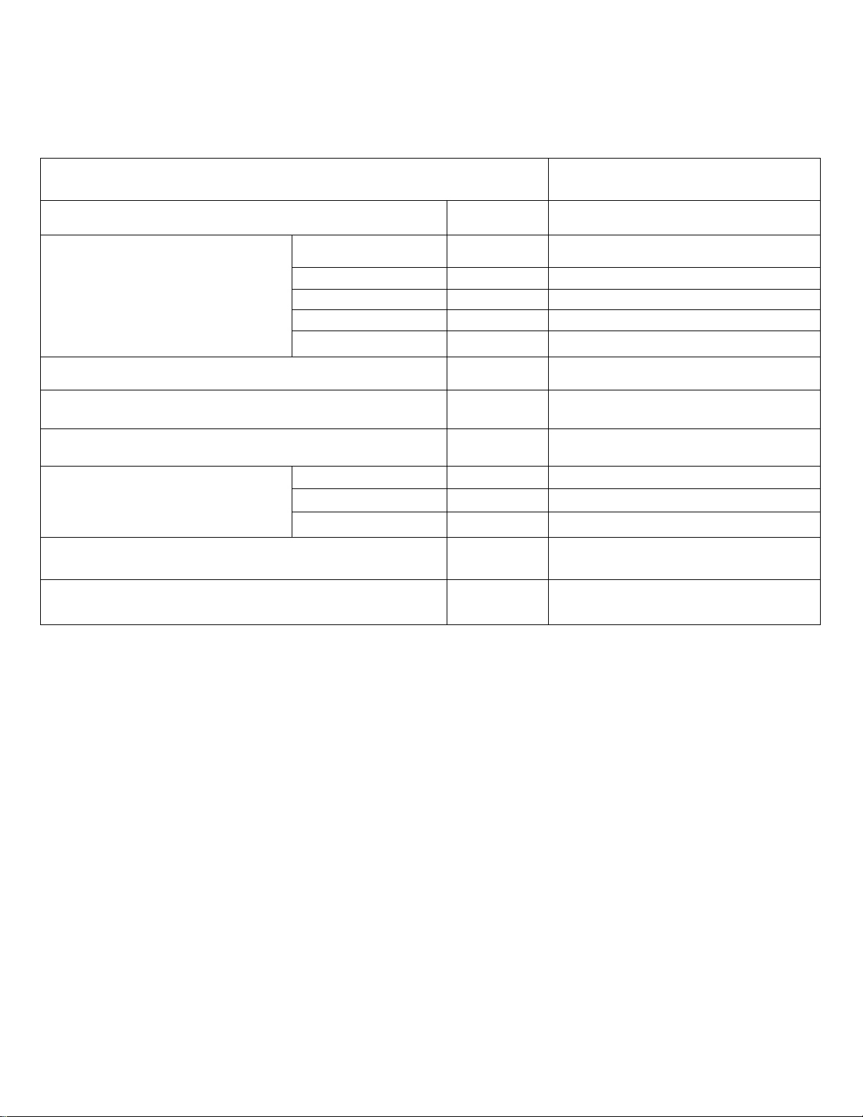
Esvecifícaciones Del Producto
MODELO
CAPACIDAD DE ENFRIAMIENTO
CLASIFICACIÓN DE
LA ELECTRICIDAD
EER
DESHUMIDIFICACION
CIRCULACION DE AIRE DE LA HABITACION
DIMENSIONES
PESO NETO
Fase
Ciclos
Voltaje
Comente de uso
Fuente de Energía Watts
Alto pulgadas 16-7/8
Ancho
Profundidad
CW-1406BU
Btu/h 13 500
Sencilla
Hz 60
V 115
Amps 12,0
1 420
Btu/Watt*h 9,5
Pints/hr 3,4
Cf/min 390
pulgadas 26
pulgadas 25-7/32
Libras 126
PESO BRUTO
*Las especificaciones están sujetas a cambios por mejoras sin previo aviso
Si todavía tiene problemas después de haber verificado todos los puntos anteriores, llame a
su revendedor o al centro de servicio autorizado de Panasonic
E! servicio de atención al público está disponible las 24 horas del día discando
1-800-545-2672
Matsushita Consumer Electronics
Company, Division of Matsushita
Electric Corporation of America
One Panasonic Way Secaucus,
New Jersey 07094
Panasonic Sales Company,
Division of Matsushita Electric of
Puerto Rico, Inc (“PSC”)
Ave 65 de Infantena, Km 9 5
San Gabnel Industnal Park, Carolina,
Puerto Rico 00985
Libras 143
Pnnted in Malaysia
F9512-1
F561157
 Loading...