

CS-E18DKRW CS-E21DKRS
12 Installation Instructions
Required tools for Installation Works
1 . P hilips screw driv er 5 . S panner 9 . G as leak detector 1 3 . M ultimeter
2. L ev el g aug e 6 . P ipe cutter 1 0 . M easuring tape 1 4 . Torque wrench
1 8 N .m (1 .8 kg f.m)
4 2 N .m (4 .2 kg f.m)
5 5 N .m (5 .5 kg f.m)
3 . E lectric drill, hole core drill
(ø7 0 mm)
7 . Reamer 1 1 . Thermometer 1 5 . V acuum pump
4 . H ex ag onal wrench (4 mm) 8 . K nife 1 2. M eg ameter 1 6 . G aug e manifold
12.1. Safe ty P re cautions
•
Read the following “S A F E TY P RE C A U TIO N S ” carefully before installation.
•
E lectrical work must be installed by a licensed electrician. Be sure to use the correct rating of the power plug and main circuit
for the model to be installed.
•
The caution items stated here must be followed because these important contents are related to safety. The meaning of each
indication used is as below. Incorrect installation due to ig noring of the instruction will cause harm or damag e, and the
seriousness is classified by the following indications.
WA RN IN G
This indication shows the possibility of causing death or serious injury.
CA U T IO N
This indication shows the possibility of causing injury or damag e to properties only.
The items to be followed are classified by the symbols:
S ymbol with backg round white denotes item that is P RO H IBITE D from doing .
•
C arry out test running to confirm that no abnormality occurs after the installation. Then, ex plain to user the operation, care and
maintenance as stated in instructions. P lease remind the customer to keep the operating instructions for future reference.
WA RN IN G
1 . E ng ag e dealer or specialist for installation. If installation done by the user is defectiv e, it will cause water leakag e, electrical shock or fire.
2. Install according to this installation instruction strictly. If installation is defectiv e, it will cause water leakag e, electrical shock or fire.
3 . U se the attached accessories parts and specified parts for installation. O therwise, it will cause the set to fall, water leakag e, fire or
electrical shock.
4 . Install at a strong and firm location which is able to withstand the set’s weig ht. If the streng th is not enoug h or installation is not properly
done, the set will drop and cause injury.
5 . F or electrical work, follow the local national wiring standard, reg ulation and this installation instruction. A n independent circuit and sing le
outlet must be used. If electrical circuit capacity is not enoug h or defect found in electrical work, it will cause electrical shock or fire.
6 . U se the specified cable (1 .5 mm2) and connect tig htly for indoor/outdoor connection. C onnect tig htly and clamp the cable so that no
ex ternal force will be acted on the terminal. If connection or fix ing is not perfect, it will cause heat-up or fire at the connection.
7 . Wire routing must be properly arrang ed so that control board cov er is fix ed properly. If control board cov er is not fix ed perfectly, it will
cause heat-up at connection point of terminal, fire or electrical shock.
8 . When carrying out piping connection, take care not to let air substances other than the specified refrig erant g o into
refrig eration cycle. O therwise, it will cause lower capacity, abnormal hig h pressure in the refrig eration cycle, ex plosion
and injury.
9 . When connecting the piping , do not allow air or any substances other than the specified refrig erant (R4 1 0 A ) to enter the
refrig eration cycle. O therwise, this may lower the capacity, cause abnormally hig h pressure in the refrig eration cycle, and
possibly result in ex plosion and injury.
1 0 .
•
When connecting the piping , do not use any ex isting (R22) pipes and flare nuts. U sing such same may cause
abnormally hig h pressure in the refrig eration cycle (piping ), and possibly result in ex plosion and injury. U se only
R4 1 0 A materials.
•
Thickness of copper pipes used with R4 1 0 A must be more than 0 .8 mm. N ev er use copper pipes thinner than 0 .8
mm.
•
It is desirable that the amount of residual oil is less than 4 0 mg /1 0 m.
1 1 . D o not modify the leng th of the power supply cord or use of the ex tension cord, and do not share the sing le outlet with
other electrical appliances. O therwise, it will cause fire or electrical shock.
8 1
CS-E15 DKRW CU -E1 5 DKR / CS-E18DKRW CU -E18DKR / CS-E21DKRS CU -E21DK R
CAUTION
1. This equipment must be earthed. It may cause electrical shock if grounding is not perfect.
2. Do not install the unit at place where leakage of flammable gas may occur. In case gas leaks and accumulates at
surrounding of the unit, it may cause fire.
3. Carry out drainage piping as mentioned in installation instructions. If drainage is not perfect, water may enter the room and damage the
furniture.
ATTENTION
1. Selection of the installation location.
Select an installation location which is rigid and strong enough to support or hold the unit, and select a location for easy maintenance.
2. Power supply connection to the room air conditioner.
Connect the power supply cord of the room air conditioner to the mains using one of the following method.
Power supply point shall be the place where there is ease for access for the power disconnection in case of emergency.
In some countries, permanent connection of this room air conditioner to the power supply is prohibited.
1. Power supply connection to the receptacle using a power plug.
Use an approved 16A (E18DK, E21DK) power plug with earth pin for connection to the socket.
2. Power supply connection to a circuit breaker for the permanent connection. Use an approved 16A circuit breaker for the permanent
connection. It must be a double pole switch with a minimum 3.5 mm contact gap.
3. Do not release refrigerant.
Do not release refrigerant during piping work for installation, reinstallation and during repairing a refrigeration parts. Take care of the
liquid refrigerant, it may cause frostbite.
4. Installation work.
It may need two people to carry out the installation work.
5. Do not install this appliance in a laundry room or other location where water may drip from the ceiling, etc.
82
CS-E15DKRW CU-E15DKR / CS-E18DKRW CU-E18DKR / CS-E21DKRS CU- E21DKR
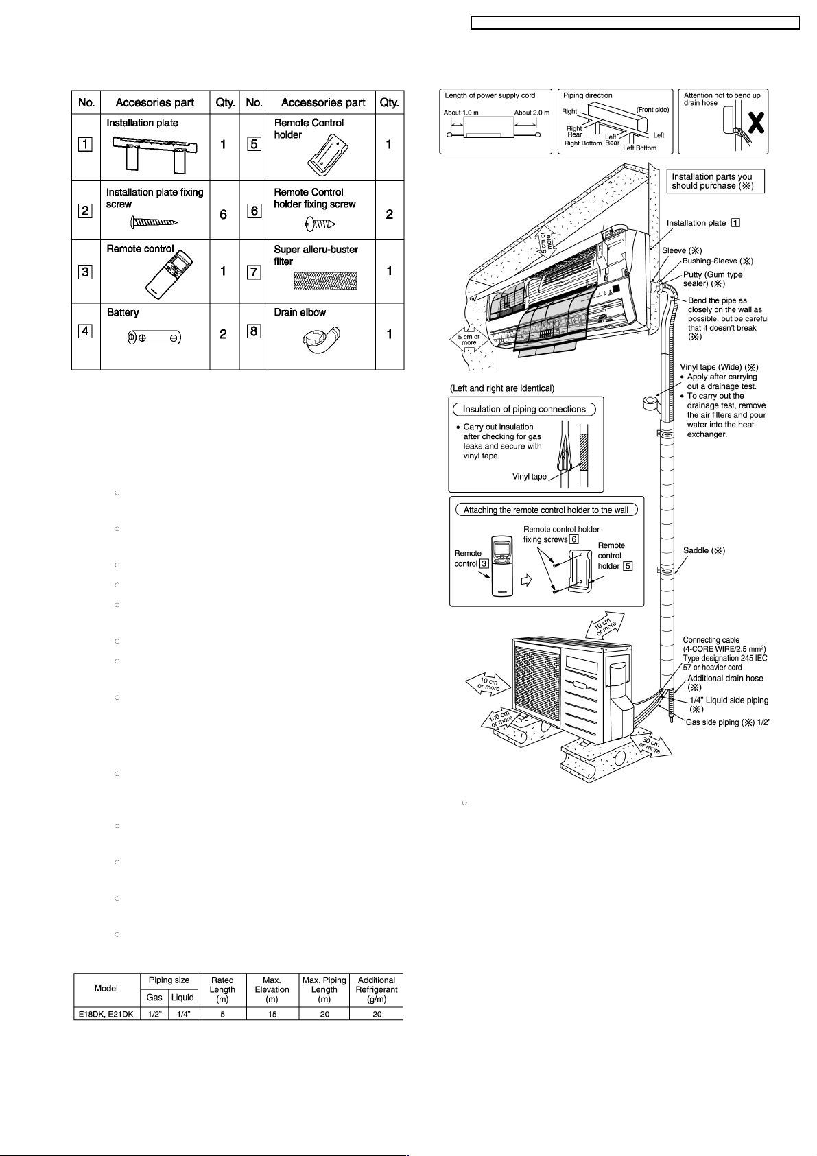
Attached accessories
Applicable piping kit
CZ -4F5, 7, 10BP (E18DK, E21DK)
Select the b est location
INDOOR UNIT
•
There should not be any heat source or steam near
the unit.
•
There should not be any obstacles blocking the air
circulation.
•
A place where air circulation in the room is good.
•
A place where drainage can be easily done.
•
A place where noise prevention is taken into
consideration.
•
Do not install the unit near the door way.
•
Ensure the spaces indicated by arrows from the wall,
ceiling, fence or other obstacles.
•
Recommended installation height for indoor unit
shall be at least 2.5 m.
OUTDOOR UNIT
•
If an awning is built over the unit to prevent direct
sunlight or rain, be careful that heat radiation from
the condenser is not obstructed.
•
There should not be any animal or plant which could
be affected by hot air discharged.
•
Keep the spaces indicated by arrows from wall,
ceiling, fence or other obstacles.
•
Do not place any obstacles which may cause a short
circuit of the discharged air.
•
If piping length is over 10 m, additional refrigerant
should be added as shown in the table.
Indoor/Outdoor Unit Installation Diag ram
•
This illustration is for explanation purposes only.
The indoor unit will actually face a different way.
83
CS-E15DKRW CU-E15DKR / CS-E18DKRW CU-E18DKR / CS-E21DKRS CU- E21DKR

12.2.1. SELECT THE BEST LOCATION
(Refer to “Select the best location”
section)
12.2.2. HOW TO F IX INSTALLATION
PLATE
The mounting wall is strong and solid enough to prevent it from
the vibration.
The centre of installation plate should be at more than 550 mm
at right and left of the wall.
The distance from installation plate edge to ceiling should more
than 67 mm.
From installation plate left edge to unit’s left side is 47 mm.
From installation plate right edge to unit’s right is 73 mm.
:
:
:
For left side piping, piping connection for liquid should be
about 126 mm from this line.
For left side piping, piping connection for gas should be
about 174 mm from this line.
For left side piping, piping connecting cable should be
about 984 mm from this line.
1. Mount the installation plate on the wall with 5 screws or
more.
(If mounting the unit on the concrete wall consider using
anchor bolts.)
•
Always mount the installation plate horiz ontally by
aligning the marking-off line with the thread and using a
level gauge.
2. Drill the piping plate hole with ø70 mm hole-core drill.
•
Line according to the arrows marked on the lower left
and right side of the installation plate. The meeting point
of the extended line is the centre of the hole. Another
method is by putting measuring tape at position as
shown in the diagram above. The hole centre is
obtained by measuring the distance namely 150 mm
and 125 mm for left and right hole respectively.
•
Drill the piping hole at either the right or the left and the
hole should be slightly slanted to the outdoor side.
12.2.3 . TO DRILL A HOLE IN THE WALL
AND INSTALL A SLEEV E OF
PIPING
1. Insert the piping sleeve to the hole.
2. Fix the bushing to the sleeve.
3. Cut the sleeve until it extrudes about 15 mm from the wall.
Caution
When the wall is hollow, please be sure to use the
sleeve for tube ass’y to prevent dangers caused by
mice biting the connecting cable.
4. Finish by sealing the sleeve with putty or caulking
compound at the final stage.
12.2.4 . INDOOR UNIT INSTALLATION
1.
F or the right rear p ip ing
2.
F or the right and right bottom p ip ing
12.2. Indoor Unit
84
CS-E15DKRW CU-E15DKR / CS-E18DKRW CU-E18DKR / CS-E21DKRS CU- E21DKR

3.
For the embedded piping
(This can be used for left rear piping & left bottom piping also.)
85
CS-E15DKRW CU-E15DKR / CS-E18DKRW CU-E18DKR / CS-E21DKRS CU- E21DKR

12.2.5. CONNECT THE CABLE TO THE
INDOOR UNIT
1. The inside and outside connecting cable can be connected
without removing the front grille.
2. Connecting cable between indoor unit and outdoor unit
shall be approved polychloroprene sheathed 4 × 1.5 mm
2
flexible cord, type designation 245 IEC 57 or heavier cord.
•
Ensure the color of wires of outdoor unit and the
terminal Nos. are the same to the indoor’s respectively.
•
Earth lead wire shall be longer than the other lead wires
as shown in the figure for the electrical safety in case of
the slipping out of the cord from the anchorage.
•
Secure the cable onto the control board with the holder
(clamper).
86
CS-E15DKRW CU-E15DKR / CS-E18DKRW CU-E18DKR / CS-E21DKRS CU- E21DKR

INSTALLATION OF SUPER ALLERU-BUSTER FILTER
1. Open the front panel.
2. Remove the air filter.
3. Remove Supersonic air purifying device.
4. Open the Supersonic air purifying device frame.
5. Insert the super alleru-buster filter and close the Supersonic
air purifyin g device frame as show in illustration at right.
HOW TO TAKE OUT FRONT GRILLE
When reinstalling the front grille, first set the vertical
airflow direction louver to the horizontal position and
then carry out above steps 2 - 3 in the reverse order.
AUTO SWITCH OPERATION
Please follow the steps below to take out front grille if necessary such as when servicing.
1. Open the intake grille.
2. Set the vertical airflow direction louvers to the horizontal position.
3. Slide down the 3 caps on the front grille as shown in the illustration below, and then remove the 3 mounting screws.
4. Pull the lower section of the front grille towards you to remove the front grille.
The below operations will be performed by pressing the “AUTO” switch.
1. AUTO OPERATION MODE
The Auto operation will be activated immediately once the Auto Switch is pressed.
2. TEST RUN OPERATION (FOR PUMP DOWN/SERVICING PURPOSE)
The Test Run operation will be activated if the Auto Switch is pressed continuously for more than 5 sec. A “beep” sound will
occur at the fifth sec., in order to identify the starting of Test Run operation
3. REMOTE CONTROLLER RECEIVING SOUND ON/OFF
The ON/OFF of remote controller receiving sound can be change over by pressing the following step:
a. Release the Auto Switch after Test Run operation is activated.
b. Then, within 20 sec., after a., press Auto Switch for more than 5 sec.
A “beep” “beep” sound will occur at the fifth sec., then release the Auto Switch.
c. Within 20 sec. after b., press Auto Switch again. Everytime Auto Switch is pressed (within 20 sec. interval), remote
controller receiving sound status will be reversed between ON and OFF.
Long “beep” sound indicates that remote controller receiving sound is OFF.
Short “beep” sound indicate s that remote controller receiving sound is ON.
87
CS-E15DKRW CU-E15DKR / CS-E18DKRW CU-E18DKR / CS-E21DKRS CU- E21DKR

•
After selecting the best location, start installation according
to Indoor/Outdoor Unit Installation Diagram.
1. Fix the unit on concrete or rigid frame firmly and horizontally
by bolt nut. (ø10 mm).
2. When installing at roof, please consider strong wind and
earthquake. Please fasten the installation stand firmly with
bolt or nails.
Connecting The Piping To Indoor Unit
Please make flare after inserting flare nut (locate at joint portion
of tube assembly) onto the copper pipe. (In case of using long
piping)
Connect the piping
•
Align the center of piping and sufficiently tighten the flare
nut with fingers.
•
Further tighten the flare nut with torque wrench in specified
torque as stated in the table.
MODEL Piping size (Torque)
Gas Liquid
E18DK, E21DK 1/2” (55 N.m) 1/4” (18 N.m)
12.3. Outdoor Unit
12.3.1. SELECT THE BEST LOCATION
(Refer to “Select the best location” section)
12.3.2. INSTALL THE OUTDOOR UNIT
12.3.3. CONNECTING THE PIPING
Connecting The Piping To Outdoor Unit
Decide piping length and then cut by using pipe cutter. Remove burrs from cut edge. Make flare after inserting the flare nut
(located at valve) onto the copper pipe.
Align center of piping to valves and then tighten with torque wrench to the specified torque as stated in the table.
CUTTING AND FLARING THE PIPING
1. Please cut using pipe cutter and then remove the burrs.
2. Remove the burrs by using reamer. If burrs is not removed, gas leakage may be caused.
Turn the piping end down to avoid the metal powder entering the pipe.
3. Please make flare after inserting the flare nut onto the copper pipes.
88
CS-E15DKRW CU-E15DKR / CS-E18DKRW CU-E18DKR / CS-E21DKRS CU- E21DKR
 Loading...