

Panasonic CU-E12EKEB, CS-E9EKEB, CU-E9EKEB SERVICE MANUAL
Order No: MAC0510072C2
Air Conditioner
CS-E9EKEB CU-E9EKEB
CS-E12EKEB CU-E12EKEB
CONTENTS
Page Page
1 Safety Precautions 3
2 Specification
2.1. CS-E9EKEB CU-E9EKEB
2.2. CS-E12EKEB CU-E12EKEB
3 Features
3.1. Super Air Purifying System with SUPER alleru-buster
3.2. Ion Freshener
3.3. Super Quiet
3.4. Powerful Heating And Top-class Energy Effciency
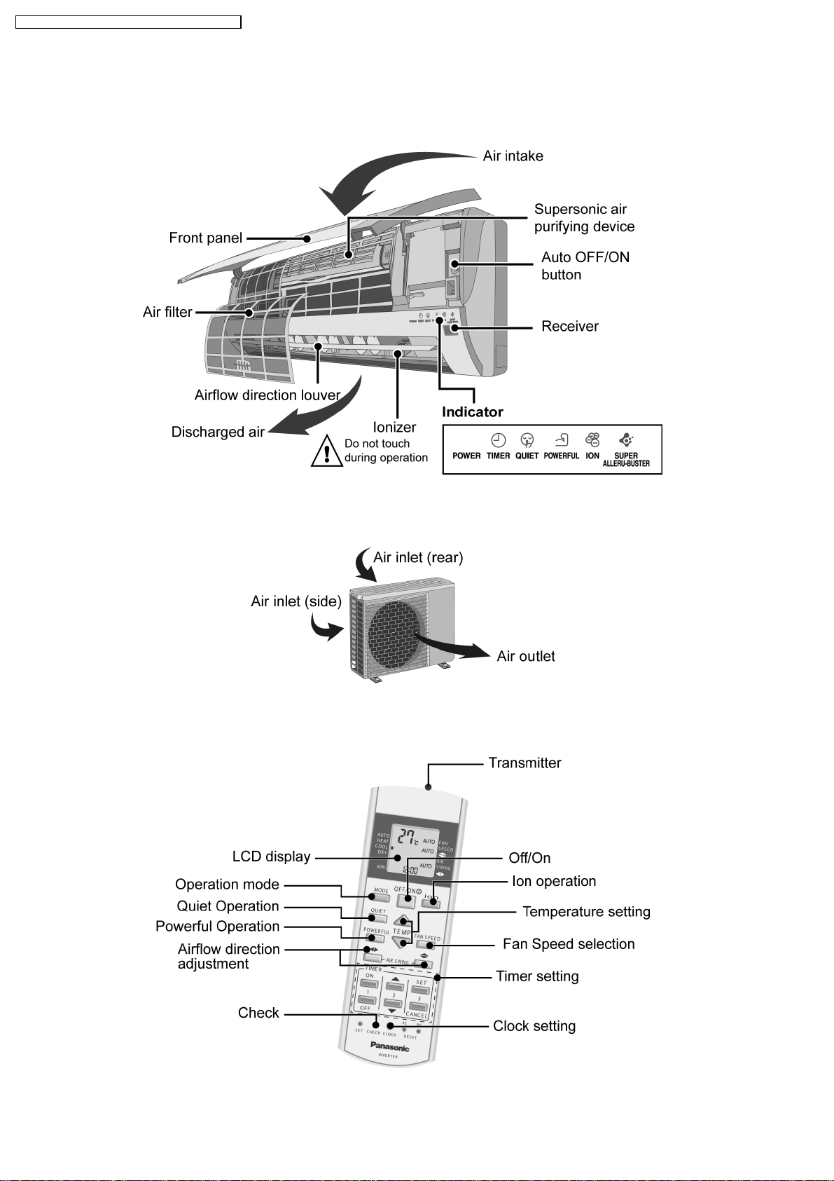
4 Location of controls and components
4.1. Indoor Unit
4.2. Outdoor Unit
4.3. Remote Control
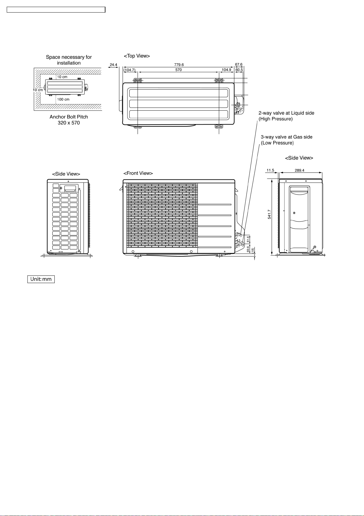
5 Dimension
5.1. Indoor Unit & Remote Control
5.2. Outdoor Unit
6 Refrigeration Cycle Diagram 13
7 Block Diagram
5
8 Wiring Diagram
5
7
9
9
9
9
9
10
10
10
10
11
11
12
8.1. CS-C9EKEB CS-C12EKEB
8.2. CU-C9EKEB CU-C12EKEB
9 Printed Circuit Board
9.1. Indoor Unit
9.2. Outdoor Unit
10 Simplified Electronic Circuit Diagram
10.1. Indoor Unit
10.2. Outdoor Unit
11 Installati on Instructions
11.1. Select The Best Location
11.2. Indoor Unit
11.3. Outdoor Unit
© 2005 Panasonic HA Air-Conditioning (M) Sdn Bhd
(11969-T). All rights reserved. Unauthorized copying
and distribution is a violation of law.
14
15
15
16
17
17
19
21
21
22
23
23
24
27

CS-E9EKEB CU-E9EKEB / CS-E12EKEB CU-E12EKEB
12 Operation And Control 30
12.1. Basic Function
12.2. Protection Control
13 Servicing Mode
13.1. Auto Switch Operation
13.2. Indicator Panel
14 Troubleshooting Guide
14.1. Refrigeration Cycle System
30
35
37
37
37
38
38
14.2. Relationship Between The Condition Of The Air
Conditioner And Pressure And Electric Current
14.3. Breakdown Self Diagnosis Function
14.4. Error Codes Table
15 Disassem bly and Assembly Instructions
39
39
40
41
15.1. Indoor Electronic Controller and Control Board
15.2. Indoor Cross Flow Fan and Fan Motor
15.3. Outdoor Propeller Fan and Fan Motor
16 Technica l Data
16.1. CS-E9EKEB CU-E9EKEB
16.2. CS-E12EKEB CU-E12EKEB
16.3. Sensible Capacity Chart
17 Exploded View And Replacement Parts List
17.1. CS-E9EKEB CS-E12EKEB
17.2. CS-E9EKEB CS-E12EKEB
17.3. CU-E9EKEB CU-E12EKEB
17.4. CU-E9EKEB CU-E12EKEB
41
43
45
47
47
53
58
59
59
60
61
62
2
CS-E9EKEB CU-E9EKEB / CS-E12EKEB CU-E12EKEB
1 Safety Precautions
• Read the following “SAFETY PRECAUTIONS” carefully before perform any servicing.
• Electrical work must be installed or serviced by a licensed electrician. Be sure to use the correct rating of the power plug and
main circuit for the model installed.
• The caution items stated here must be followed because these important contents are related to safety. The meaning of each
indication used is as below.
Incorrect installation or servicing due to ignoring of the instruction will cause harm or damage, and the seriousness is classified
by the following indications.
This indication shows the possibility of causing death or serious injury.
This indication shows the possibility of causing injury or damage to properties.
• The items to be followed are classified by the symbols:
This symbol denotes item that is PROHIBITED from doing.
• Carry out test running to confirm that no abnormality occurs after the servicing. Then, explain to user the operation, care and
maintenance as stated in instructions. Please remind the customer to keep the operating instructions for future reference.
1. Engage dealer or specialist for installation and servicing. If installation or servicing done by the user is defective, it will cause water
leakage, electrical shock or fire.
2. Install according to this installation instruction strictly. If installation is defective, it will cause water leakage, electrical shock or fire.
3. Use the attached accessories parts and specified parts for installation and servicing. Otherwise, it will cause the set to fall, water
leakage, fire or electrical shock.
4. Install at a strong and firm location which is able to withstand the set’s weight. If the strength is not enough or installation is not properly
done, the set will drop and cause injury.
5. For electrical work, follow the local national wiring standard, regulation and the installation instruction. An independent circuit and single
outlet must be used. If electrical circuit capacity is not enough or defect found in electrical work, it will cause electrical shock or fire.
6. Use the specified cable and connect tightly for indoor/outdoor connection. Connect tightly and clamp the cable so that no external force
will be acted on the terminal. If connection or fixing is not perfect, it will cause heat-up or fire at the connection.
7. Wire routing must be properly arranged so that control board cover is fixed properly. If control board cover is not fixed perfectly, it will
cause heat-up at connection point of terminal, fire or electrical shock.
8. When connecting the piping, do not allow air or any substances other than the specified refrigerant to enter the
refrigeration cycle. Otherwise, this may lower the capacity, cause abnormally high pressure in the refrigeration cycle, and
possibly result in explosion and injury.
9. Thickness of copper pipes used must be more than 0.8 mm. Never use copper pipes thinner than 0.8 mm.
10. It is desirable that the amount of residual oil is less than 40 mg/10 m.
11. Do not modify the length of the power supply cord or use of the extension cord, and do not share the single outlet with
other electrical appliances. Otherwise, it will cause fire or electrical shock.
3
CS-E9EKEB CU-E9EKEB / CS-E12EKEB CU-E12EKEB
1. The equipment must be earthed. It may cause electrical shock if grounding is not perfect.
2. Do not install the unit at place where leakage of flammable gas may occur. In case gas leaks and accumulates at
surrounding of the unit, it may cause fire.
3. Carry out drainage piping as mentioned in installation instructions. If drainage is not perfect, water may enter the room and damage the
furniture.
4. Pb free solder has a higher melting point than standard solder; typically the melting point is 50 - 70°F (30 - 40°C) higher. Please use a
high temperature soldering iron. In case of the soldering iron with temperature control, please set it to 700
20°F (370 10°C).
Pb free solder will tend to splash when heated too high (about 1100°F/600°C).
1. Selection of the installation location. Select an installation location which is rigid and strong enough to support or hold the unit, and select
a location for easy maintenance.
2. Power supply connection to the air conditioner. Connect the power supply cord of the air conditioner to the mains using one of the
following methods. Power supply point shall be the place where there is ease for access for the power disconnection in case of
emergency.
In some countries, permanent connection of this room air conditioner to the power supply is prohibited.
1. Power supply connection to the receptacle using a power plug. Use an approved power plug with earth pin for the connection to the
socket.
2. Power supply connection to a circuit breaker for the permanent connection. Use an approved circuit breaker for the permanent
connection. It must be a double pole switch with a minimum 3.5 mm contact gap.
3. Do not release refrigerant during piping work for installation, servicing, reinstallation and during repairing a refrigeration parts. Take care
of the liquid refrigerant, it may cause frostbite.
4. Installation work. It may need two people to carry out the installation work.
5. Do not install this appliance in a laundry room or other location where water may drip from the ceiling, etc.
4
CS-E9EKEB CU-E9EKEB / CS-E12EKEB CU-E12EKEB
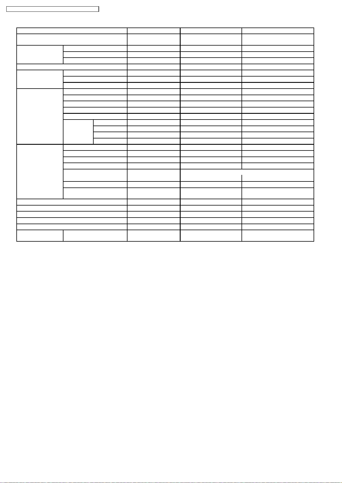
2 Specification
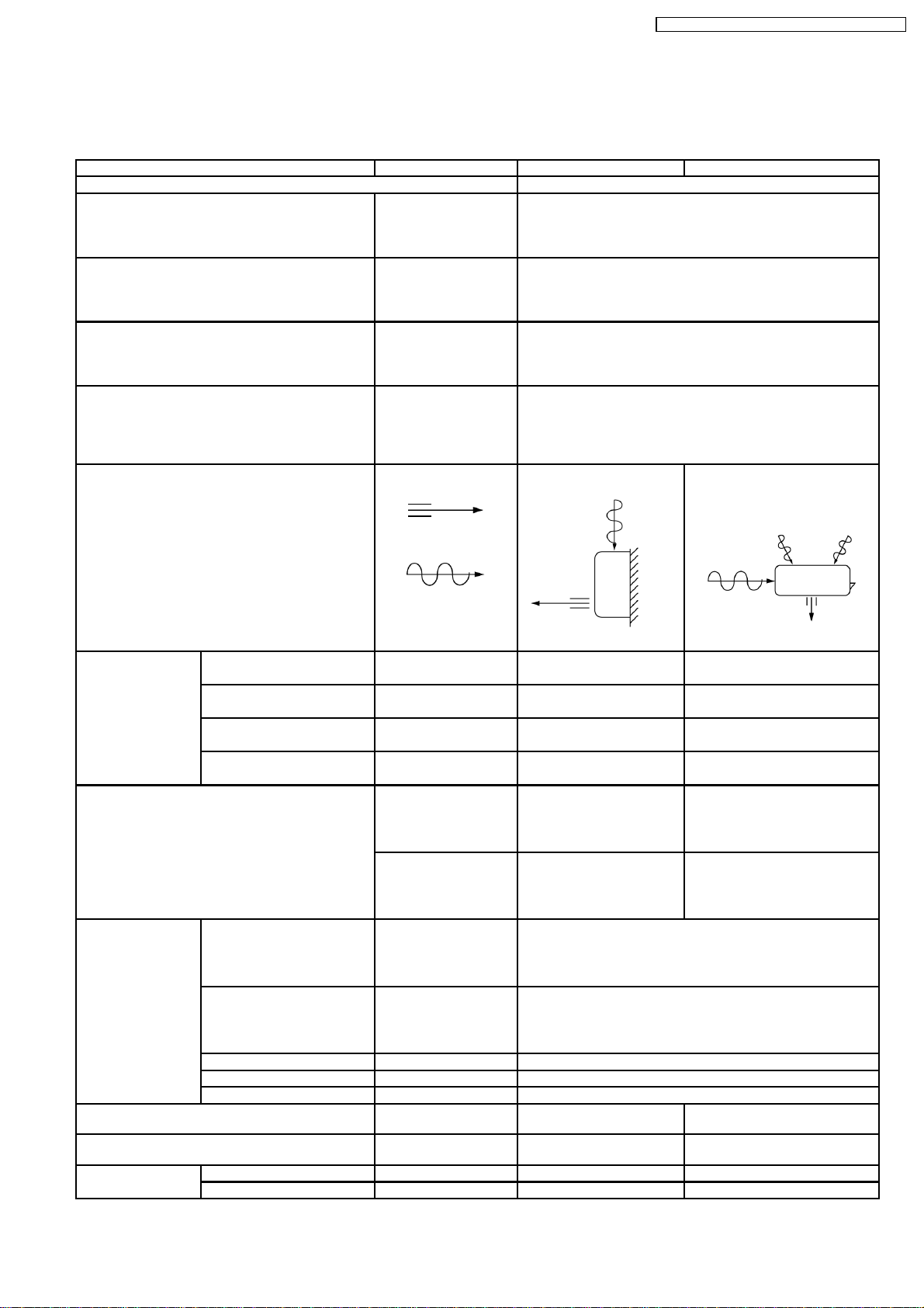
2.1. CS-E9EKEB CU-E9EKEB
Unit CS-E9EKEB CU-E9EKEB
Performance Test Condition EUROVENT
Cooling Capacity kW
Heating Capacity kW
Moisture Removal l/h
Power Source (Phase, Voltage, Cycle) ø
Airflow Method OUTLET
Air Volume Lo m3/min (cfm) Cooling; 6.2 (220) —
Me m3/min (cfm) Cooling; 7.9 (280) —
Hi m3/min (cfm) Cooling; 9.6 (340) Cooling; 29.8 (1,050)
SHi m3/min (cfm) Cooling; 9.9 (350) —
kcal/h
kcal/h
Pint/h
V
Hz
SIDE VIEW TOP VIEW
INTAKE
Heating; 6.6 (230)
Heating; 8.6 (300)
Heating; 10.5 (370)
Heating; 10.8 (380)
2.60 (0.60 - 3.00)
2,240 (520 - 2,580)
3.60 (0.60 - 5.40)
3,100 (520 - 4,640)
1.6
3.4
Single
230
50
dB (A) Cooling; High 39, Low 26 Cooling; 46
Heating; High 40, Low 27 Heating; 47
Noise Level
Power level dB Cooling; High 50 Cooling; High 59
Heating; High 51 Heating; High 60
Electrical Data Input W Cooling; 590 (120 - 750)
Heating; 845 (115 - 1,360)
Running Current A Cooling; 2.9
Heating; 4.0
EER W/W (kcal/hw) Cooling; 4.41 (3.80)
COP W/W (kcal/hw) Heating; 4.26 (3.67)
Starting Current A 4.0
Piping Connection Port
(Flare piping)
Pipe Size
(Flare piping)
Drain
Hose
Inner diameter mm 16 —
Length m 0.65 —
inch
inch
inch
inch
G ; Half Union 3/8”
L ; Half Union 1/4”
G (gas side) ; 3/8”
L (liquid side) ; 1/4”
G ; 3-way valve 3/8”
L ; 2-way valve 1/4”
G (gas side) ; 3/8”
L (liquid side) ; 1/4”
5
CS-E9EKEB CU-E9EKEB / CS-E12EKEB CU-E12EKEB
Unit CS-E9EKEB CU-E9EKEB
Power Cord Length
Number of core-wire
m 1.8
(1.5mm
2
)
Dimensions Height inch (mm) 11 - 1/32 (280) 21 - 1/4 (540)
Width inch (mm) 31 - 15/32 (799) 30 - 23/32 (780)
Depth inch (mm) 7 - 7/32 (183) 11 - 3/8 (289)
Net Weight lb (kg) 20 (9.0) 77 (35)
Compressor Type — Hermetic Motor
Motor Type — Brushless (4-pole)
Rated Output W — 750
Fan Motor Type Cross-flow Fan Propeller Fan
Material ASG20k1 P.P
Motor Type Transistor (8-poles) Induction (8-poles)
Input W 44.3 61.3
Rate Output W 30 40
Fan Speed Lo (Cool/Heat) rpm 820/880 —
Me (Cool/Heat) rpm 1,050/1,140 —
Hi (Cool/Heat) rpm 1,280/1,400 800/790
SHi (Cool/Heat) rpm 1,320/1,440 —
Heat Exchanger Description Evaporator Condenser
Tube material Copper Copper
Fin material Aluminium (Pre Coat) Aluminium
Fin Type Slit Fin Corrugated Fin
Row / Stage (Plate fin configuration, forced draft)
2/15 2/24
FPI 21 17
Size (W × H × L) mm 610 × 315 × 25.4 718.4
689.8
Refrigerant Control Device — Capillary Tube
Refrigeration Oil (cm3) — RB68A (400)
Refrigerant (R410A) g (oz) — 930 (32.8)
Thermostat Electronic Control —
Protection Device — Electronic Control
Air Filter Material
Style
P.P.
Honeycomb
—
—
× 504 × 36.4
—
Specifications are subjected to change without prior notice for further improvement.
•
6
CS-E9EKEB CU-E9EKEB / CS-E12EKEB CU-E12EKEB
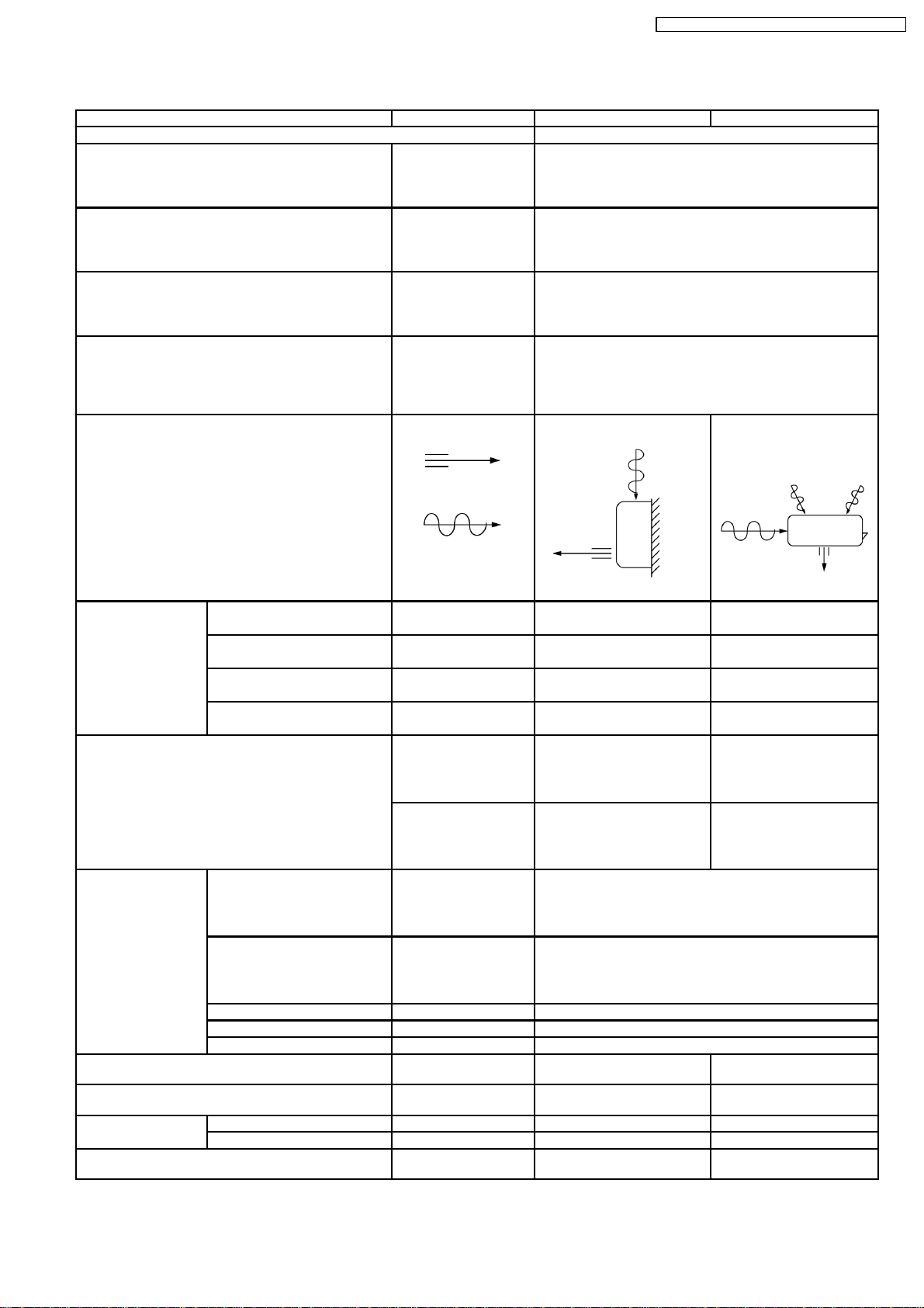
2.2. CS-E12EKEB CU-E12EKEB
Unit CS-E12EKEB CU-E12EKEB
Performance Test Condition EUROVENT
Cooling Capacity kW
Heating Capacity kW
Moisture Removal l/h
Power Source (Phase, Voltage, Cycle) ø
Airflow Method OUTLET
Air Volume Lo m3/min (cfm) Cooling; 6.9 (240) —
Me m3/min (cfm) Cooling; 8.8 (310) —
Hi m3/min (cfm) Cooling; 10.7 (380) Cooling; 31.0 (1,090)
SHi m3/min (cfm) Cooling; 11.0 (390) —
kcal/h
kcal/h
Pint/h
V
Hz
SIDE VIEW TOP VIEW
INTAKE
Heating; 8.1 (290)
Heating; 9.7 (340)
Heating; 11.2 (400)
Heating; 11.6 (410)
3.50 (0.60 - 4.00)
3,010 (520 - 3,440)
4.80 (0.60 - 6.60)
4,130 (520 - 5,680)
2.0
4.2
Single
230
50
dB (A) Cooling; High 42, Low 29 Cooling; 48
Heating; High 42, Low 33 Heating; 50
Noise Level
Power level dB Cooling; High 53 Cooling; High 61
Heating; High 53 Heating; High 63
Electrical Data Input W Cooling; 920 (120 - 1,180)
Heating; 1,260 (115 - 1,850)
Running Current A Cooling; 4.3
Heating; 5.8
EER W/W (kcal/hw) Cooling; 3.80 (3.27)
COP W/W (kcal/hw) Heating; 3.81 (3.28)
Starting Current A 5.8
Piping Connection Port
(Flare piping)
Pipe Size
(Flare piping)
Drain
Hose
Power Cord Length
Number of core-wire
Inner diameter mm 16 —
Length m 0.65 —
inch
inch
inch
inch
G ; Half Union 1/2”
L ; Half Union 1/4”
G (gas side) ; 1/2”
L (liquid side) ; 1/4”
1.8
2
(1.5mm
)
G ; 3-way valve 1/2”
L ; 2-way valve 1/4”
G (gas side) ; 1/2”
L (liquid side) ; 1/4”
—
—
7
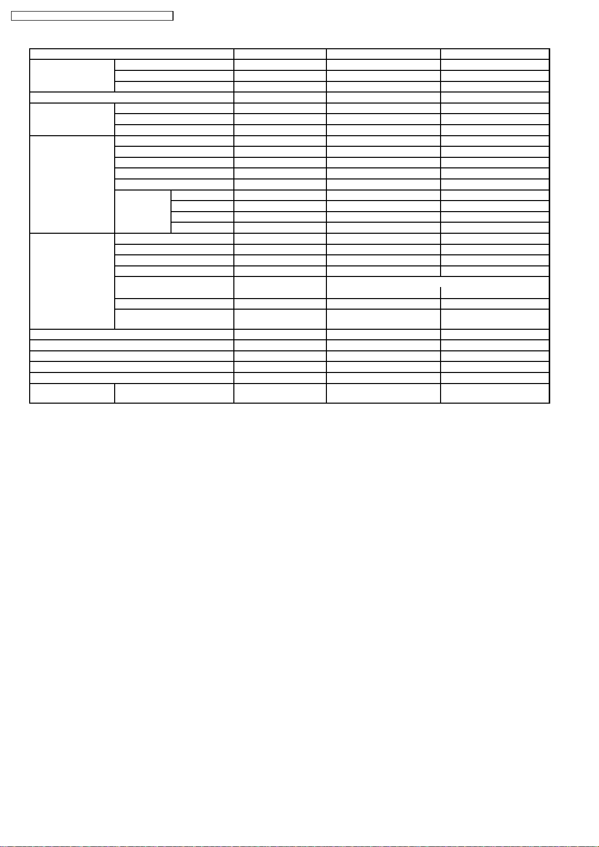
CS-E9EKEB CU-E9EKEB / CS-E12EKEB CU-E12EKEB
Unit CS-E12EKEB CU-E12EKEB
Dimensions Height inch (mm) 11 - 1/32 (280) 21 - 1/4 (540)
Width inch (mm) 31 - 15/32 (799) 30 - 23/32 (780)
Depth inch (mm) 7 - 7/32 (183) 11 - 3/8 (289)
Net Weight lb (kg) 20 (9.0) 79 (36)
Compressor Type — Hermetic Motor
Motor Type — Brushless (4-pole)
Rated Output W — 750
Fan Motor Type Cross-flow Fan Propeller Fan
Material ASG20k1 P.P
Motor Type Transistor (8-poles) Induction (8-poles)
Input W 44.3 65.9
Rate Output W 30 40
Fan Speed Lo (Cool/Heat) rpm 910/1,080 —
Me (Cool/Heat) rpm 1,165/1,290 —
Hi (Cool/Heat) rpm 1,420/1,500 840 / 820
SHi (Cool/Heat) rpm 1,460/1,540 —
Heat Exchanger Description Evaporator Condenser
Tube material Copper Copper
Fin material Aluminium (Pre Coat) Aluminium
Fin Type Slit Fin Corrugated Fin
Row / Stage (Plate fin configuration, forced draft)
2/15 2/24
FPI 21 17
Size (W × H × L) mm 610 × 315 × 25.4 718.4
Refrigerant Control Device — Capillary Tube
Refrigeration Oil (cm3) — RB68A (400)
Refrigerant (R410A) g (oz) — 970 (34.2)
Thermostat Electronic Control —
Protection Device — Electronic Control
Air Filter Material
Style
P.P.
Honeycomb
689.8
× 504 × 36.4
—
Specifications are subjected to change without prior notice for further improvement.
•
8
3 Features
CS-E9EKEB CU-E9EKEB / CS-E12EKEB CU-E12EKEB
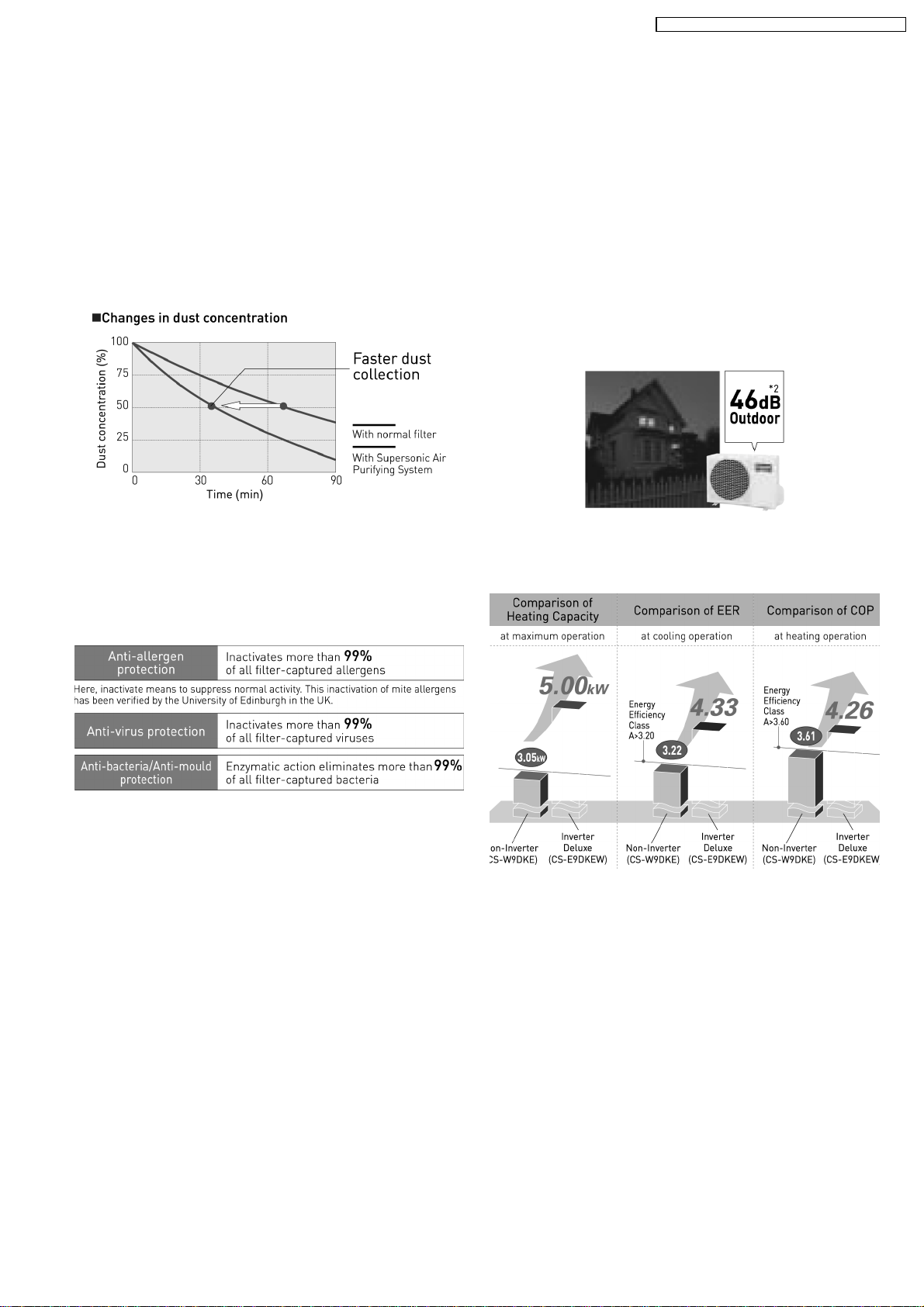
3.1. Super Air Purifying System
with SUPER alleru-buster
3.1.1. Supersonic Air Purifying System
• The Supersonic Air Purifying System incorporated in the
indoor unit generates supersonic waves.
• The system works in combination with the filter to collects
dust and dirt in the air for faster, more efficient air
purification.
3.1.2. SUPER alleru-buster filter
• The SUPER alleru-buster filter combines three effects in
one—anti-allergen, anti-virus, anti-bacteria protection—to
keep room air clean and healthful.
3.2. Ion Freshener
• Around 20,000 negative ions/cc are generated to freshen
the room. It’s like being next to a waterfall or in a forest.
3.3. Super Quiet
• The indoor unit operates at a whisper-quiet 26dB. You can
also press the Quiet Mode button to lower the operating
noise 3 dB. We’ve reduced the noise of the outdoor unit,
too, with the e-scroll Compressor and 2-Wing Fan. You can
run the air conditioner at night and enjoy a deeper, more
comfortable sleep, and without bothering your neighbours.
3.4. Powerful Heating And Top-
class Energy Effciency
9
CS-E9EKEB CU-E9EKEB / CS-E12EKEB CU-E12EKEB
4 Location of controls and components
4.1. Indoor Unit
4.2. Outdoor Unit
4.3. Remote Control
10
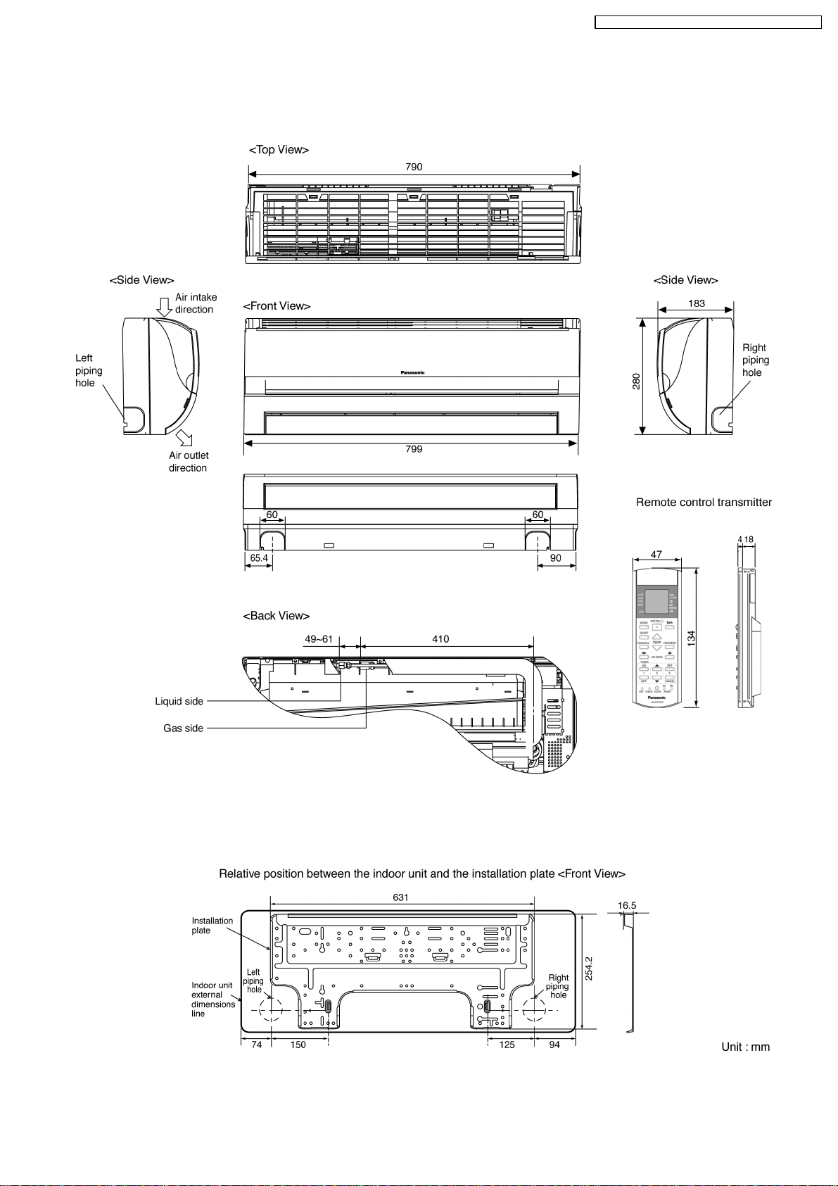
5 Dimension
5.1. Indoor Unit & Remote Control
CS-E9EKEB CU-E9EKEB / CS-E12EKEB CU-E12EKEB
11
CS-E9EKEB CU-E9EKEB / CS-E12EKEB CU-E12EKEB
5.2. Outdoor Unit
12
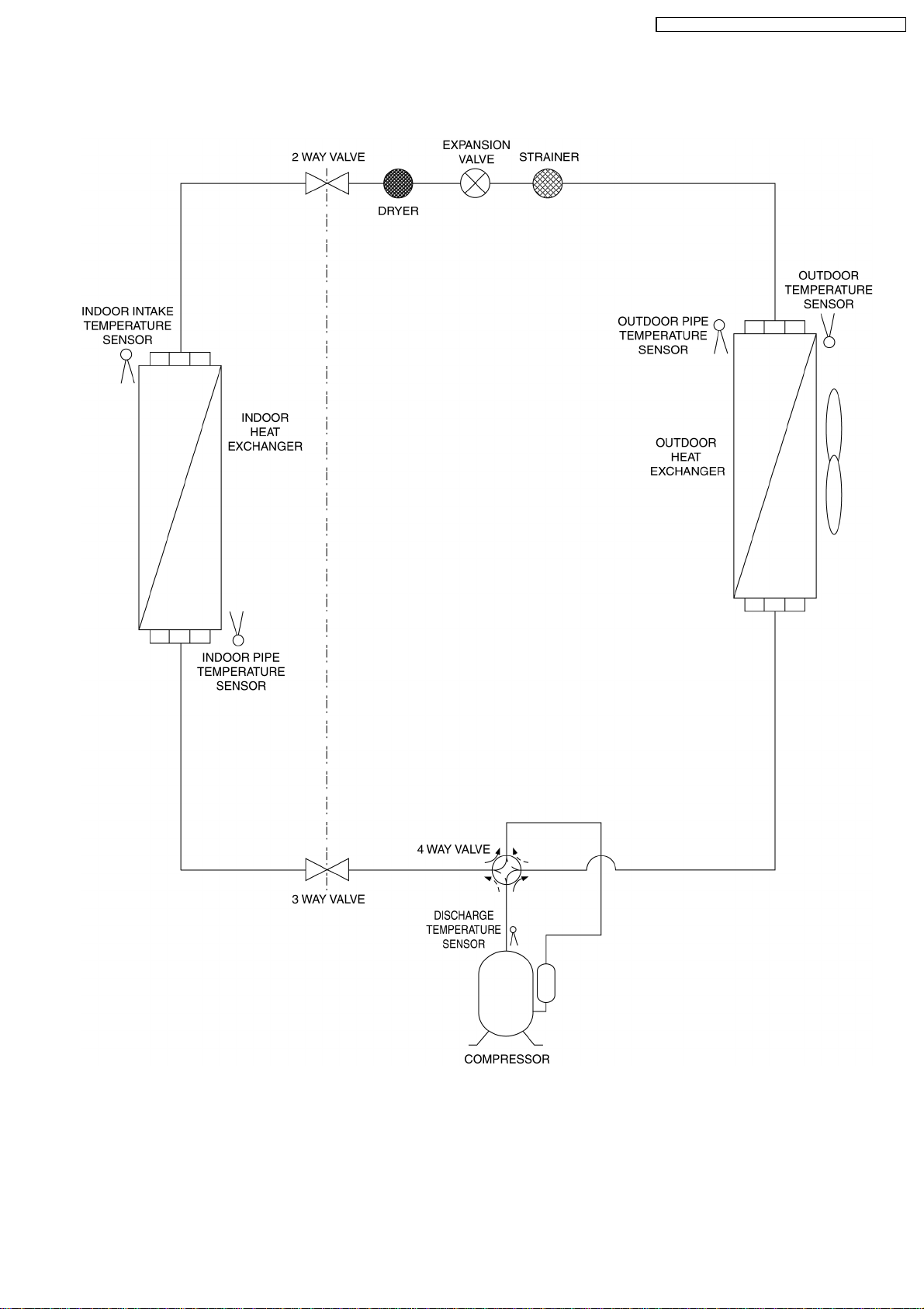
6 Refrigeration Cycle Diagram
CS-E9EKEB CU-E9EKEB / CS-E12EKEB CU-E12EKEB
13
CS-E9EKEB CU-E9EKEB / CS-E12EKEB CU-E12EKEB
7 Block Diagram
14
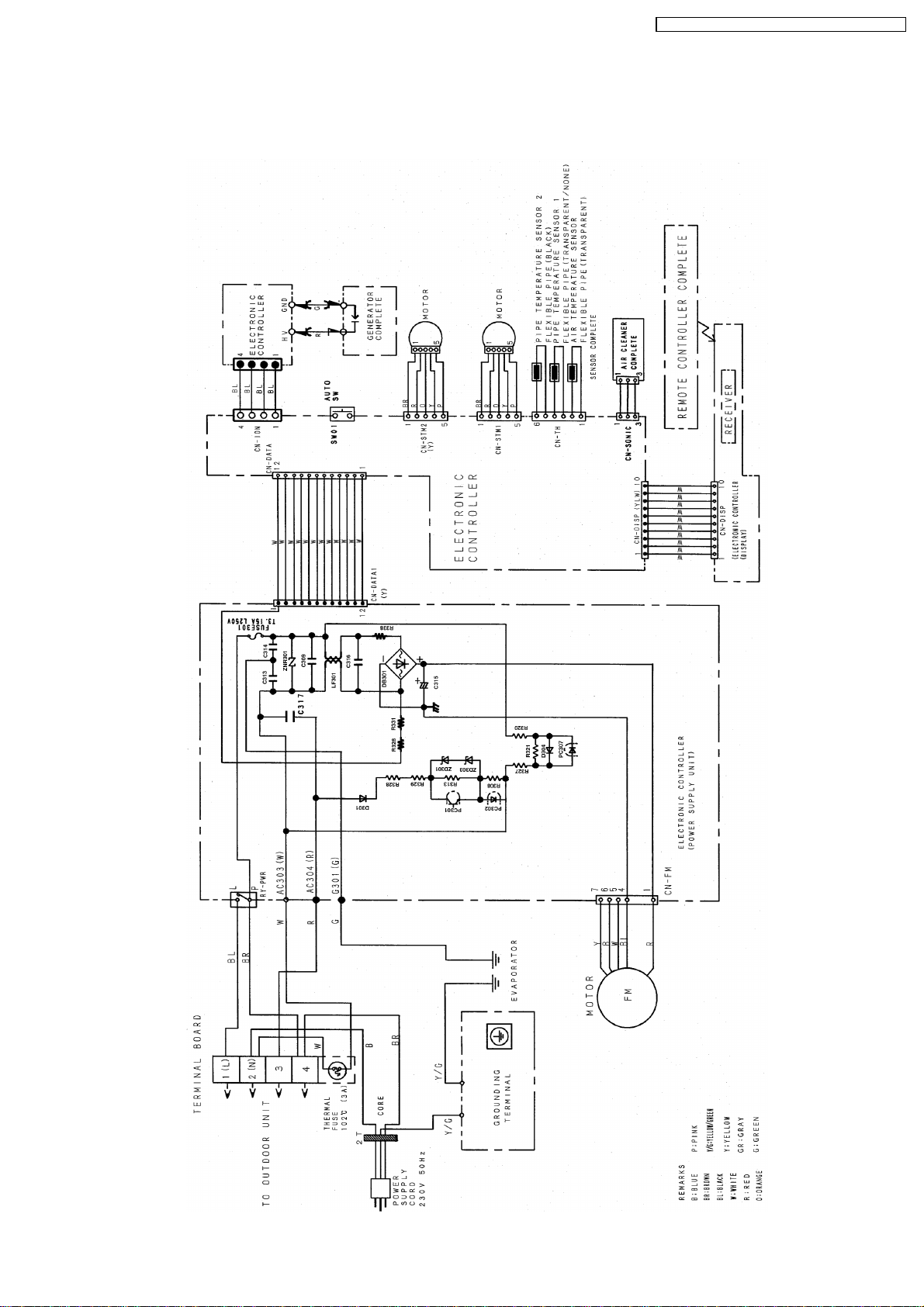
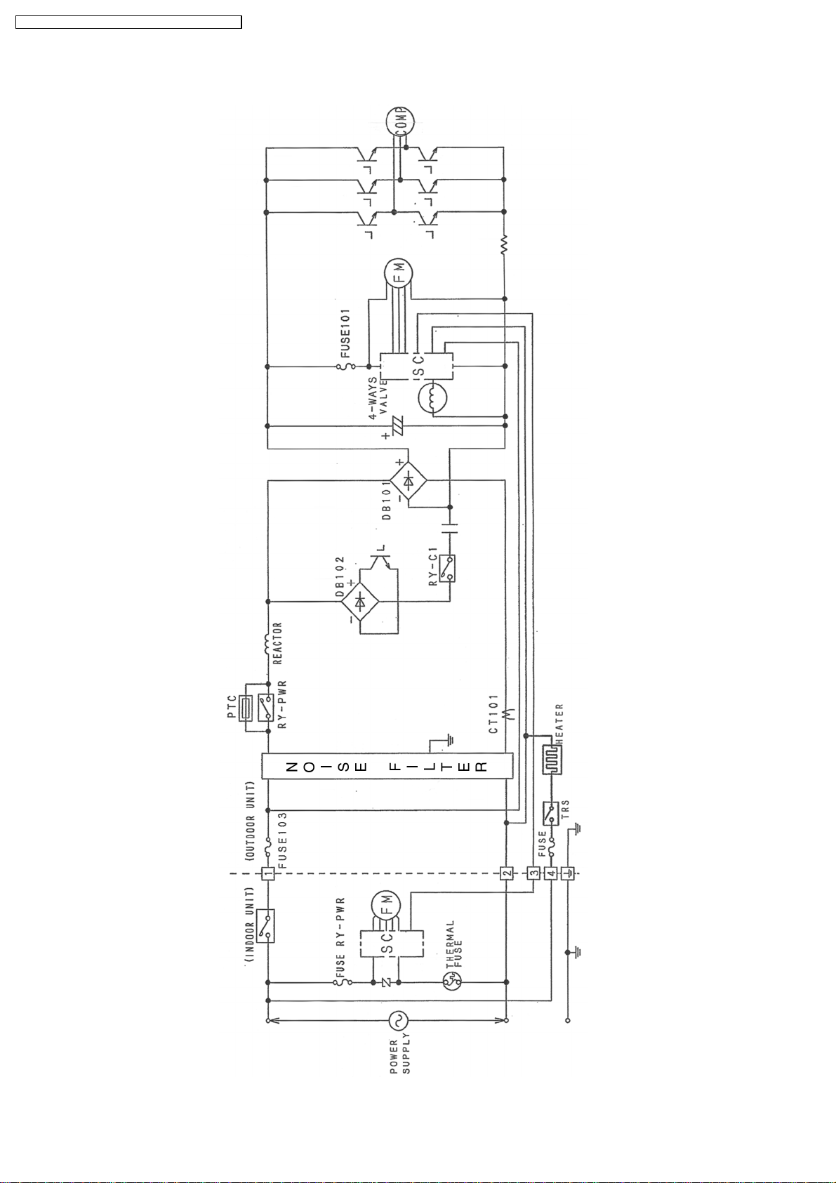
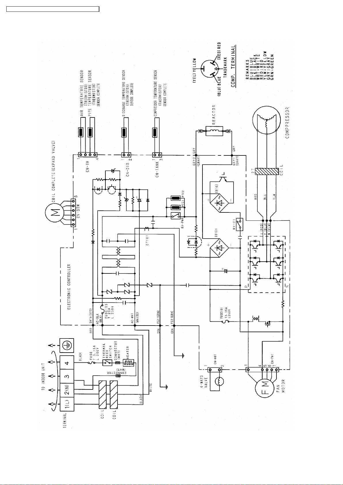
8 Wiring Diagram
8.1. CS-C9EKEB CS-C12EKEB
CS-E9EKEB CU-E9EKEB / CS-E12EKEB CU-E12EKEB
15
CS-E9EKEB CU-E9EKEB / CS-E12EKEB CU-E12EKEB
8.2. CU-C9EKEB CU-C12EKEB
16
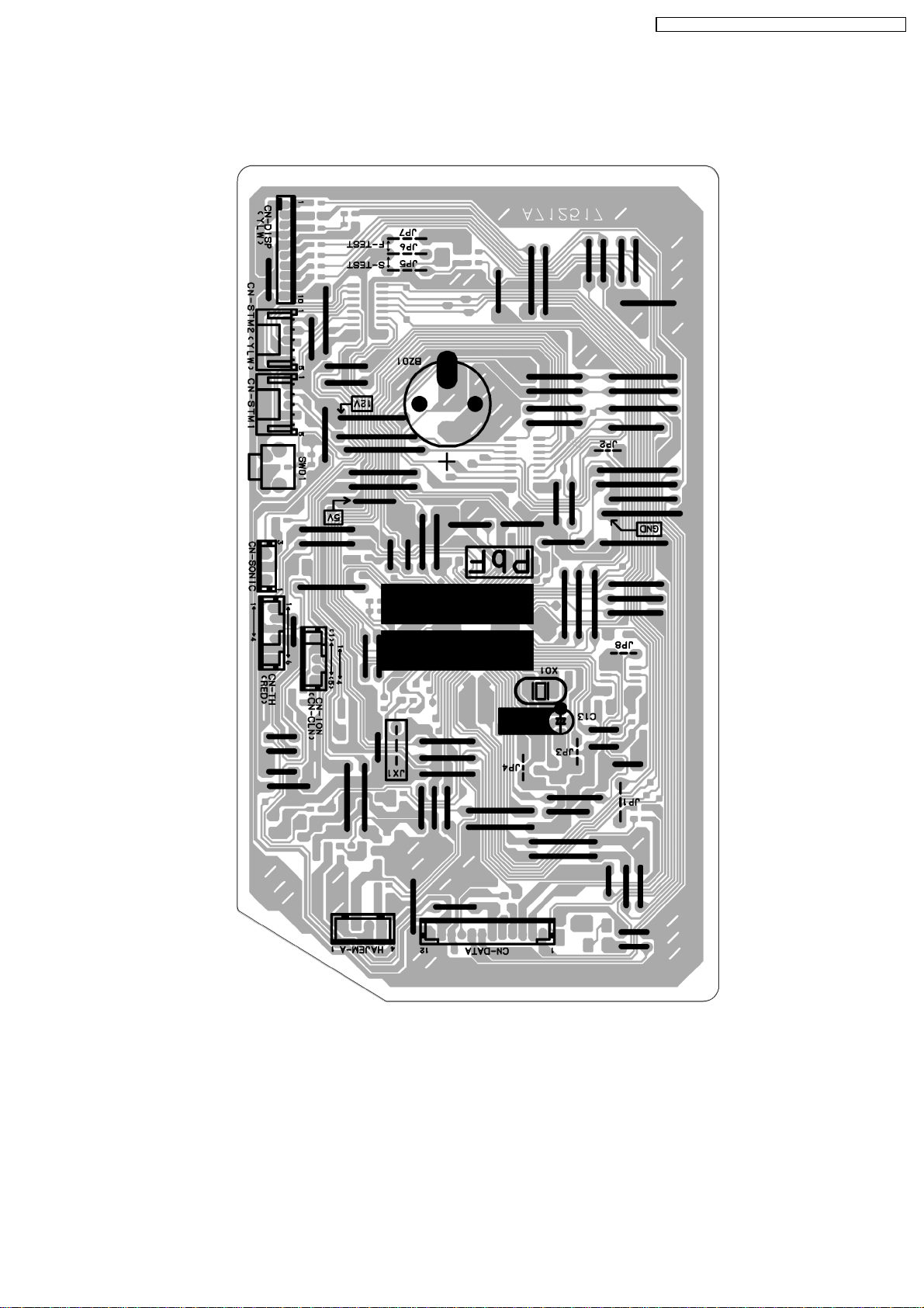
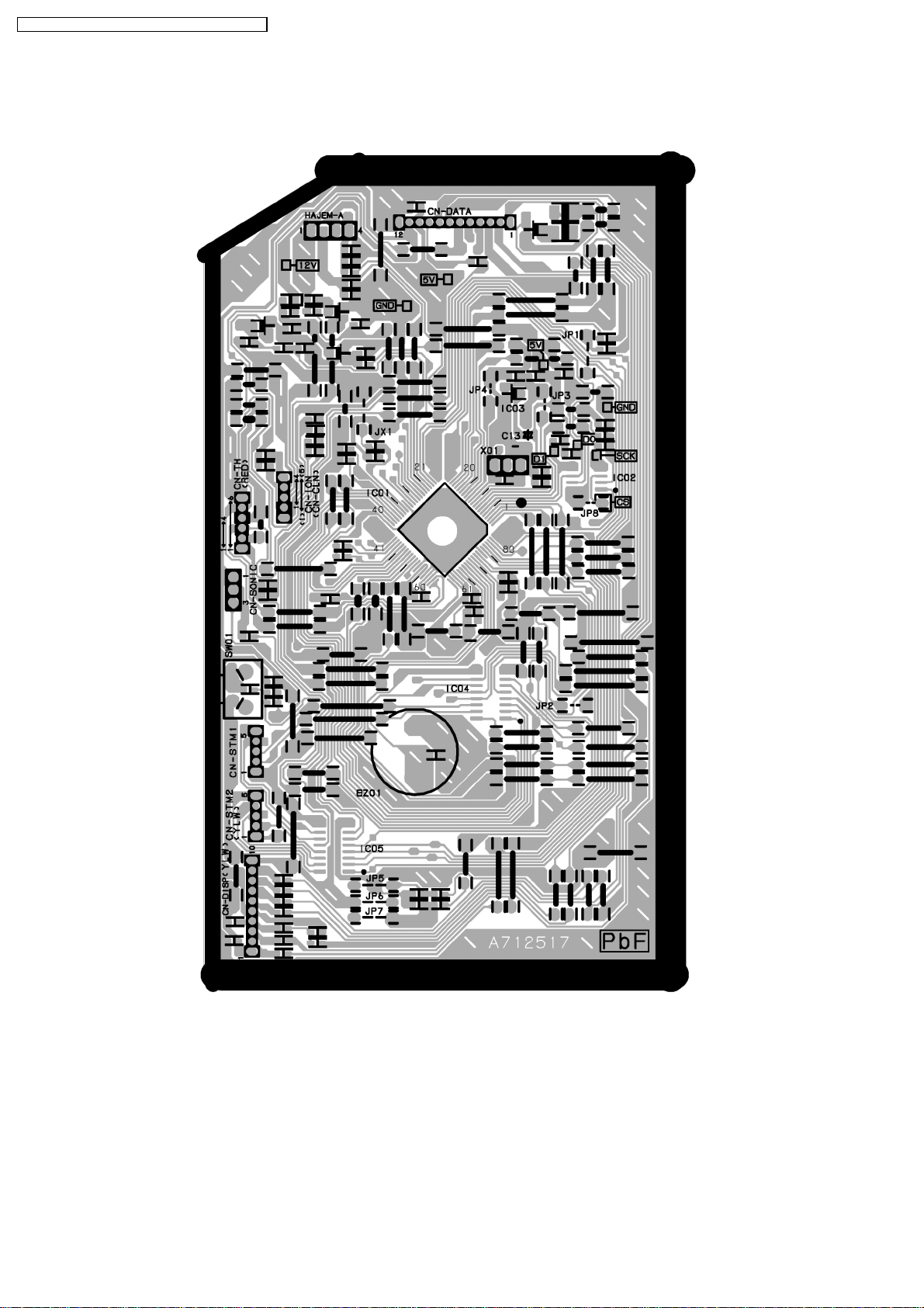
9 Printed Circuit Board
9.1. Indoor Unit
CS-E9EKEB CU-E9EKEB / CS-E12EKEB CU-E12EKEB
17
CS-E9EKEB CU-E9EKEB / CS-E12EKEB CU-E12EKEB
18
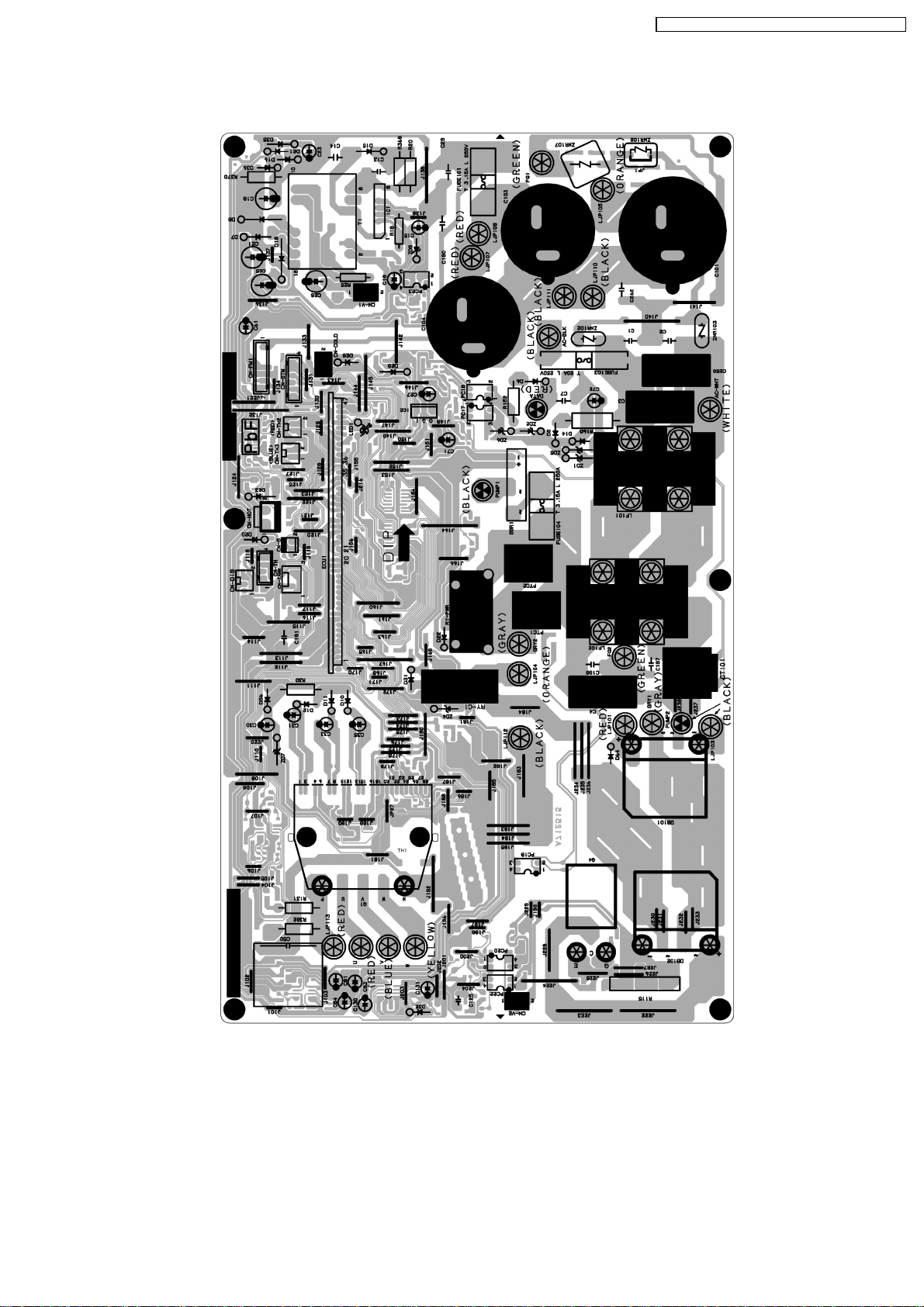
9.2. Outdoor Unit
CS-E9EKEB CU-E9EKEB / CS-E12EKEB CU-E12EKEB
19
 Loading...