

Panasonic CT-F2136LC Service Manual
Colour Television
CT-F2136LC
GP41 Chassis
Order No. MTV0601437CE
Specification
Power Source AC SINGLE 110-220 V, 50/60 Hz
Power Consumption 67 W
Standby condition : 2 W
Aerial Terminal Impedance : 75Ω, Coaxial type
Tuning System
Receiving System MTS STEREO
Receiving Channels Regular TV
VHF BAND 2-13 (NTSC M U.S.A)
UHF BAND 14-69 (NTSC M U.S.A.)
CATV 1-125 (U.S.A. CATV)
Intermediate Frequency 38.0 MHz
Video 31.5 MHz (D, K) / 32.5 MHz (B, G)
Sound 33.57 MHz (PAL) /
Colour 33.6 MHz (SECAM)
Video/Audio/Terminals
DVD
Frequency Synthesizer
Auto Search Tuning
Pos : 100 Positions
32.0 MHz (I) / 32.5 MHz (M)
34.42 MHz (NTSC) /
33.75 MHz (SECAM)
Y 1.0 Vp-p, 75Ω
P
B
P
R
AV 1, 2, 3
Video in 1.0 Vp-p, 75Ω
Audio in Approx. 0.5V, 47KΩ
Audio Amp AUDIO L-R 0.5VRMS
(PHONE JACK TYPE x 2)
High Voltage 27.5 ±1.5 at zero
Picture Tube A51LYZ295X Type 21 (500 mm)
Audio Output 16 W speaker
Dimensions (W x D x H) 648 mm x 488 mm x 473 mm
Weight (Mass) 27 kg (Net)
Note:
Specifications are subject to change without notice. Mass and
dimensions shown are approximate .
0.7 Vp-p, 75Ω
0.7 Vp-p, 75Ω
beam current
Measured diagonally,
90° deflection
© 2006 Matsushita Electric Industrial Co., Ltd. All
rights reserved. Unauthorized copying and
distribution is a violation of law.
CT-F2136LC
CONTENTS
Page Page
1 Safety Precautions 3
1.1. General Guide
1.2. Leakage Current Cold Check
1.3. Leakage Current Hot Check (See Fig. 1)
1.4. X-Radiation
1.5. GP41 Block Diagram
2 Service Hints
2.1. HOW TO MOVE CHASSIS INTO SERVICE POSITION.
3 Market Mode Function
3.1. Service Mode Access
3.2. Service Mode 1 Controls
3.3. Service Mode 1 Function
3.4. Service Mode 2 Controls (OPTION data 1 ~ 3)
4 Adjustment Procedure
3
3
3
3
4
5
5
6
6
6
6
6
7
4.1. Adjustment Procedure
4.2. COLOUR PURITY
4.3. CONVERGENCE
4.4. WHITE BALANCE (MARKET MODE CHK 4)
4.5. ADJUSTMENT OF CRT VRS
5 Conductor Views
6 Schematic Diagrams
6.1. SCHEMATIC DIAGRAM FOR GP41 CHASSIS
6.2. A Board
6.3. L Board
7 Parts Locations
8 Replacement Parts List
8.1. Replacement Parts List Notes
8.2. Replacement Parts List
7
7
8
9
10
11
12
12
14
19
22
23
23
24
2
CT-F2136LC
1 Safety Precautions
1.1. General Guide
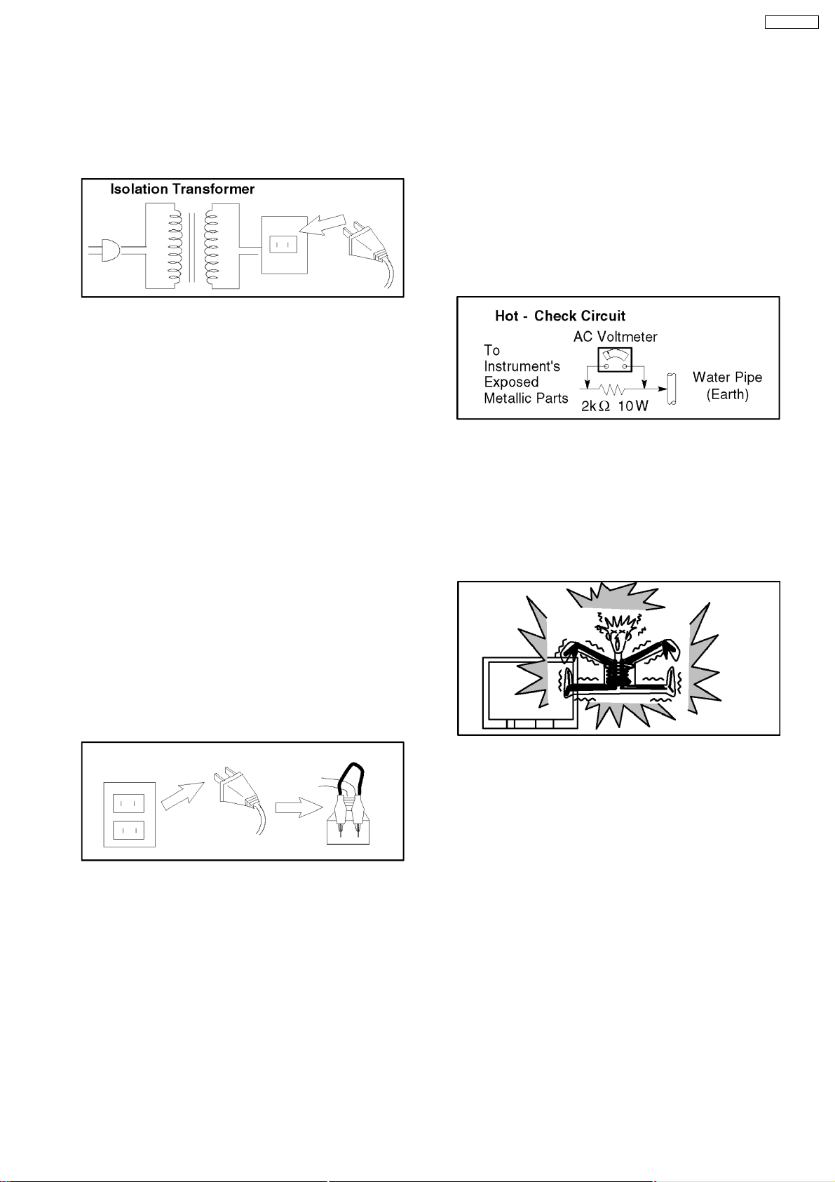
1. It is advisable to insert an isolation transformer in the AC
supply before servicing a hot chassis. Fig. 1.
Fig. 1
2. When servicing, observe the original lead dress, especia lly
the lead dress in the high voltage circuits. If a short circuit is
found, replace all parts which have been overheated or
damaged by the short circuit.
3. After servicing, observe that all the protective devices such
as insulation barriers, insulation papers, shields, and
isolation R-C combinations, are properly installed.
4. When the receiver is not to be used for a long period of
time, unplug the power cord from the AC outlet.
5. Potential, as high as
is in operation. Operation of the receiver without the
receiver power supply. Servicing should not be attempted
by anyone who is not thoroughly familiar with the
precautions necessary when working on high voltage
equipment. Always discharge the anode of the picture tube
to the receiver chassis before handling the tube.
After servicing make the following leakage current checks to
prevent the customer from being exposed to shock
hazards.
29kV
kV is present when this receiver
1.3. Leakage Current Hot Check
(See Fig. 1)
1. Plug the AC cord directly into the AC outlet. Do not use an
isolation transformer for this check.
2. Connect a 2 kΩ, 10 W resistor in series with an exposed
metallic part on the receiver and an earth such as a water
pipe.
3. Use an AC voltmeter, with high impedance type, to
measure the potential across the resistor.
4. Check each exposed metallic part, and measure the
voltage at each point. Fig. 3.
Fig. 3
5. Reverse the AC plug in the AC outlet and repeat each of the
above measurements.
6. The potential any point should not exceed
case of a measurement being outside of the limits specified,
there is a possibility of a shock hazard, and the receiver
should be repaired and re-checked before it is returned to
the customer. Fig. 4.
1.0 V rms
. In the
1.2. Leakage Current Cold Check
1. Unplug the AC cord and connect a jumper between the two
prongs on the plug. Fig. 2.
Fig. 2
2. Turn on the receiver’s power switch.
3. Measure the resistance value, with an ohmmeter, between
the jumpered AC plug and each exposed metallic cabinet
part on the receiver, such as screw heads, aerials,
connectors, control shafts, etc. When the exposed metallic
part has a return path to the chassis, the reading should be
ΩΩΩΩ
4M
between
not have a return path to the chassis, the reading must be
zero.
and 20 M
ΩΩΩΩ
. When the exposed metal does
Fig. 4
1.4. X-Radiation
Warning :
1. The potential sources of X-Radiation in TV sets are the EHT
section and the picture tube.
2. When using a picture tube test rig for service, ensure that
the rig is capable of handling
Radiation.
Note:
It is important to use an accurate periodically calibrated
high voltage meter.
1. Set the brightness to minimum.
2. Measure the High Voltage. The meter reading should
indicate
tolerance, immediate service and correction is required to
prevent the possibility of premature component failure.
3. To prevent the possibility of X-Radiation, it is essential to
use the specified picture tube.
27.5 ± 1.5V
. If the meter indication is out of
29 kV
without causing X-
3
_
_
CT-F2136LC
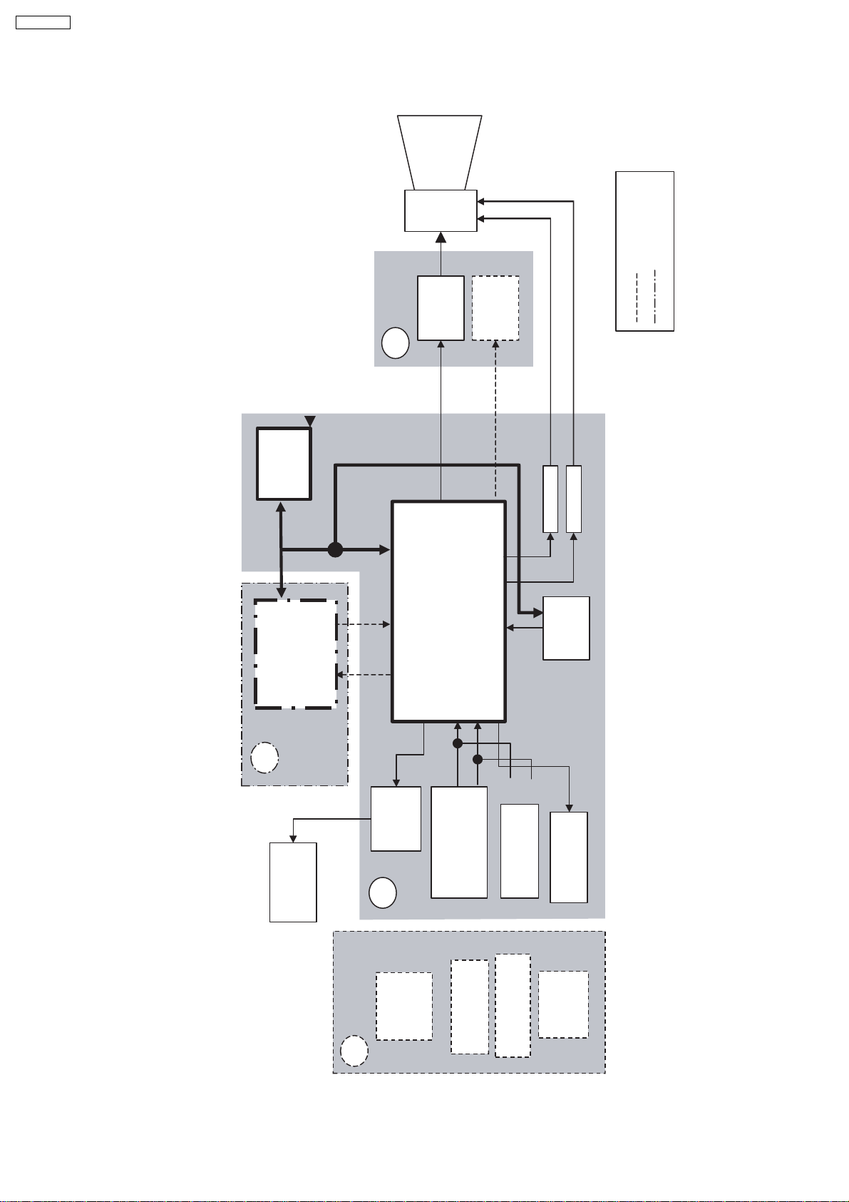
1.5. GP41 Block Diagram
CRT
coil
defl.
29" models
CRT
DRIVE
L
VM DRIVE
PIP models
IC1101
EEPROM
RGB
SCL SDA
SCL
SDA
R/G/B
PVP
IN
IC1801
CVBS
GP41 CHASSIS BLOCK DIAGRAM
PP
SPEAKER
R/G/B
CVBS OUT
AMP
AUDIO
A
VCT-IF
OUT
AUDIO
IC2301
REAR INPUTS
VM
V
H
IC601
IF
IN
IN
V
A
MON_OUT
AV1 : V/L/R
AV3 : YUV/V/L/R
V OUT
TUNER
AV2 : V/L/R
FRONT INPUTS
MON_OUT
H OUT
V/L/R
MAIN
POWER
SWITCH
G
AV2 : V/L/R
FRONT INPUTS
GEOMAGNETIC
AMP
IC2401
WOOFER
4

2 Service Hints
2.1. HOW TO MOVE CHASSIS INTO SERVICE POSITION.
1. Remove 9 screws.
CT-F2136LC
2. Draw out Main Chassis.
3. Stand the Main Chassis.
5

CT-F2136LC
3 Market Mode Function
3.1. Service Mode Access
1. Set timer ON.
2. Press remote’s RECALL (
3. Set to normal mode : Press the volume down button on front, together press the off timer button on remote control.
3.2. Service Mode 1 Controls
) and panel’s volume down key simultaneously to enter SERVICE 1.
1. Key 3 / 4
previous / next service 1 item
2. Key 8 / 9
adjust user brightness (-/+)
3. Program up / down
program position up / down
4. Volume +
increment of selected item
3.3. Service Mode 1 Function
1. H-POS
-128~127
2. V-POS
-128~127
3. H-AMP
-128~127
4. V-AMP
-128~127
5. EW-AMP1
-128~127
6. LOW_Corner
-128~127
7. TRAPEZ 1
-128~127
8. UPPER_Corner
-128~127
9. V-LIN
-128~127
10. V-SYM
-128~127
5. Volume -
decrement of selected item
6. OK (remote)
store / save selected item
7. Normal (remote)
exit service mode
11. ANGEL
-128~127
12. BOW
-128~127
13. DVCO
-128~127
14. H-POS
-128~127
15. G-CUT OFF
N/A
16. B-CUT OFF
0~511
17. R-DRIVE
0~511
18. G-DRIVE
0~511
19. B-DRIVE
0~511
20. SUB-Bright
-128~127
3.4. Service Mode 2 Controls (OPTION data 1 ~ 3)
1. Key 3 / 4
previous / next service 2 item
2. Key 8 / 9
toggle for options bit 0 - 7
3. Program up / down
program position up / down
4. Volume +
increment of selected item
5. Volume -
decrement of selected item
6. OK (remote)
store / save selected item
7. Normal (remote)
exit service mode
NOTE: Service mode 2 options bit refer to each model spec.
6
4 Adjustment Procedure
4.1. Adjustment Procedure
4.1.1. +B Voltage
CT-F2136LC
Item / preparation
1. Operate the TV set.
2. Set control as follows :
Brightness ........... minimum
Contrast ............... minimum
Adjustment procedure
1. Confirm the DC voltage at the indicated test points, as
follows :
TPD 15 : 3.35 ± 0.2V
TPD 16 : 141 ± 2V
TPD 17 : 8.2 ± 0.5V
TPD 18 : 1.9 ± 0.2V
TPD 19 : 5.2 ± 0.2V
TPD 20 : 175 ± 15V
4.1.2. High Voltage
Item / preparation
1. Receive the crosshatch pattern.
2. Set to 0 Beam.
Screen VR .......... minimum
Contrast .............. minimum
Adjustment procedure
1. Connect a DC voltage meter to D866 and confirm the +B
voltage is 141.0 ± 2V.
2. Connect a high frequency voltmeter to heater and confirm
that voltage reads 6.30 ± 0.24 (VRMS).
3. Normalize the brightness and contrast.
4.1.3. NTSC TINT COLOUR
Item / preparation
1. Connect oscilloscope probe to TPL1 (R OUT) with 10k
series resistor.
2. Press Main Menu and set system to use AV-NTSC (3.58
MHz).
DYNAMIC ................... Normal
Channel CLR Set ..... STD
Adjustment procedure
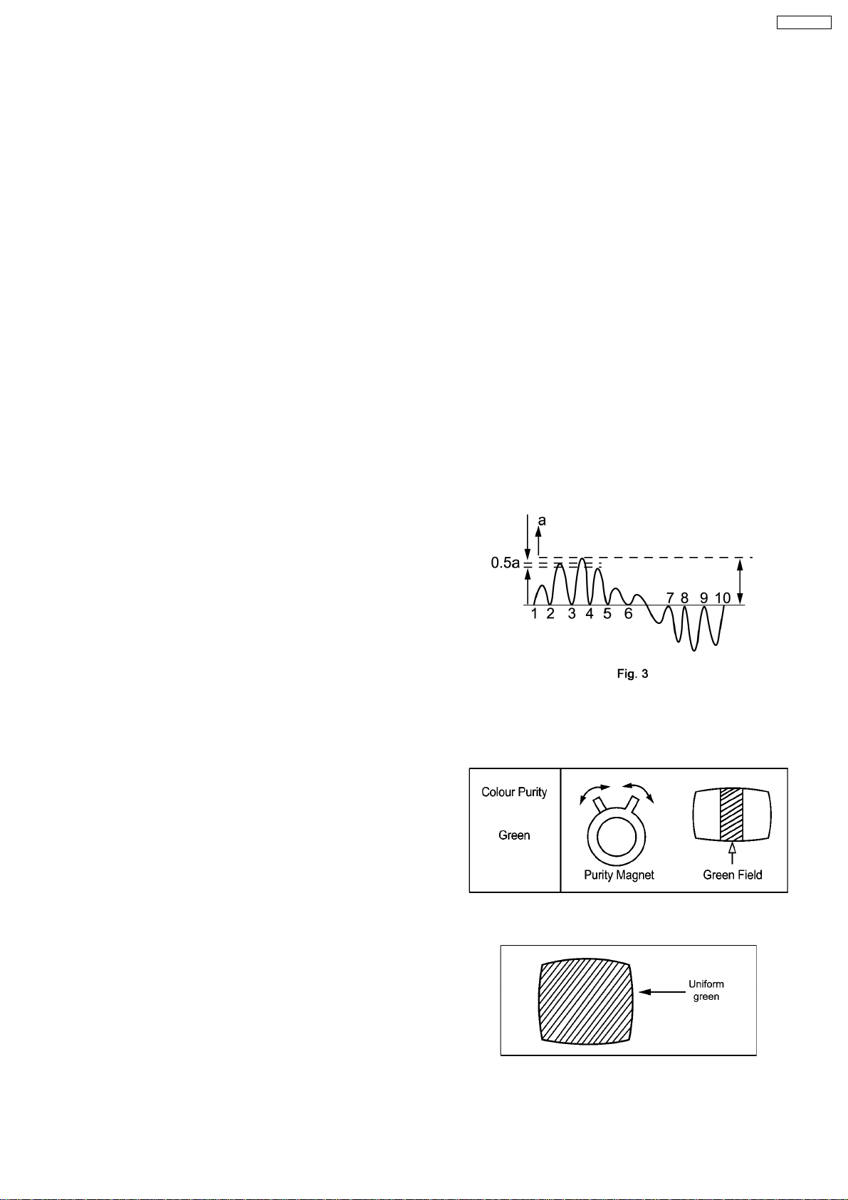
1. Adjust Sub-Tint so that No. 2, 3 and 4 becomes level
waveform is similar to Fig. 3.
2. Confirm phase at Tint is changes more than ± 15 by Tint
control.
3. Confirm that colour level is maximum when colour DAC is
adjusted to maximum position.
Note:
Use remote control only when adjusting user mode to
Sub-Tint.
Ω
4.2. COLOUR PURITY
1. Set Bright and Contrast controls to their maximum
positions.
2. Operate the TV set over 60 minutes.
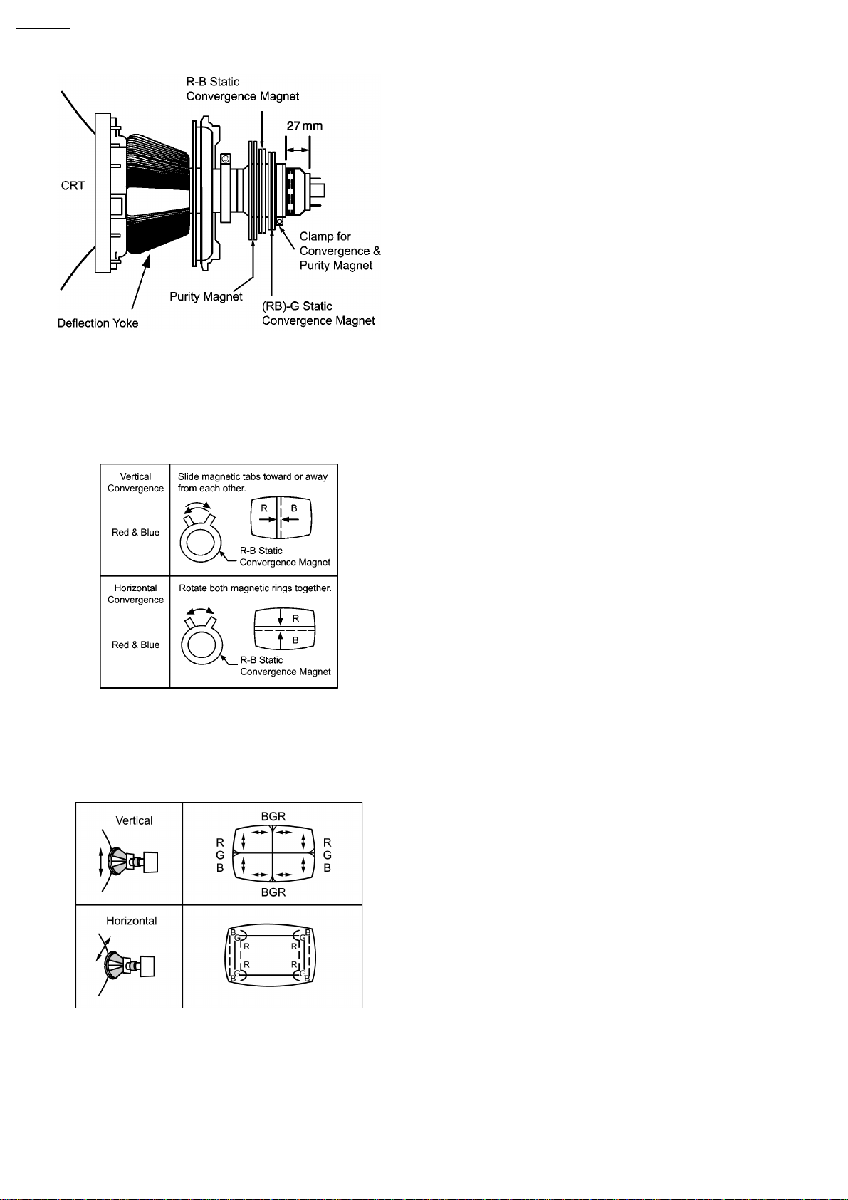
3. Full degauss the picture tube by using an external
degaussing coil. By rotating R-B static convergence
magnet.
4. Apply a crosshatch pattern signal and adjust roughly the
static convergence magnets.
5. Apply a green pattern signal.
6. Loosen a clamp screw for the Deflection Yoke and move
the Deflection Yoke as close to the purity magnet as
possible.
7. Adjust the purity magnet so that a vertical green field is
obtained at the center of the screen.
8. Slowly press the Deflection Yoke and set it where a uniform
green field is obtained.
9. Adjust roughly the Low Light controls and make sure that a
uniform white field is obtained.
10. Tighten the clamp screw.
7
CT-F2136LC
4.3. CONVERGENCE
1. Apply a crosshatch pattern signal and set Contrast control
to the maximum position.
2. Adjust Bright control to obtain a clear pattern.
3. Adjust Red and Blue line at center of the screen.
4. Adjust Red and Blue with Green line at center of the screen
by rotating (RB)-G static convergence magnet.
5. Lock convergence magnets with silicone sealer.
6. Remove the DY wedges and slightly tilt the Deflection Yoke
vertically.
7. Fix the Deflection Yoke by re-inserting the DY wedges.
8. If purity error is found, repeat “Colour Purity” adjustment.
8
4.4. WHITE BALANCE (MARKET MODE CHK 4)
Preparation
1. Receive a colour bar signal with colour “OFF”, and operate
the TV set for more than 30 minutes.
2. Set the picture menu to “DYNAMIC NORMAL” and the AI to
off.
3. Connect an oscilloscope to KG on L BOARD.
4. Set the TV set to Market Mode : white balance adjustment
(CHK 4).
5. Screen VR : Min.
6. Set the data level of RGB CUT OFF / DRIVE and SUB
BRIGHT.
Adjustment
1. Select G-CUTOFF adjustment mode and collapse vertical
scan.
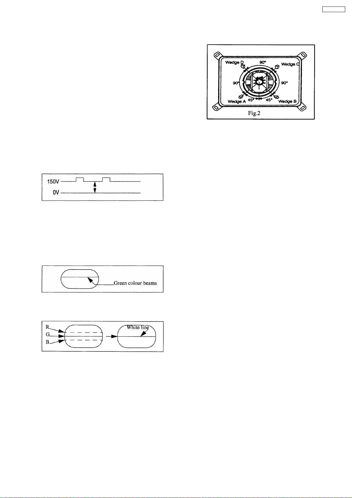
2. Adjust G-CUTOFF control to become the DC=0 V to video
level at 150 V as shown in Fig. 1.
8. Wedge A shown in Fig. 2 should be fixed within a range of
45° to the left of the vertical line as shown.
9. After inserting wedge A, insert wedges B, C and D.
The wedges should be set 90° apart from each other.
10. Be certain that the four wedges are firmly fixed and the
Deflection Yoke is tightly clamped in place otherwise the
Deflection Yoke may shift its position and cause a loss of
convergence and purity.
CT-F2136LC
Fig. 1
3. Slowly turn the screen control clockwise until a green colour
horizontal line appears on the picture tube. This is the
setting point for the screen control.
Note:
Do not adjust the G-CUTOFF setting in the following
procedure.
4. Adjust the remaining R and B-CUTOFF controls so as to
get a white horizontal line on the screen.
5. Return to full field SCAN by pushing the position 5 key on
the remote control.
6. Adjust the R-Drive and B-Drive controls as to obtain a
uniform white on the white bar of the greyscale pattern.
7. Confirm correct B/W rendition and greyscale tracking or
repeat CUTOFF and drive control setup.
Note:
Write down the original value for each address adjustment
before adjusting anything.
9
 Loading...