

Panasonic CT-36D31UE, CT-36D11UE, CT-32D31UE, CT-32D11UE, CT-27D21UE Owner’s Manual
...
nasonlc
Color Television
Operating Instructions
CT-27D11
CT-27D11 U
CT-27D21
CT-27D21 U
CT-27D31
CT-27D31 U
CT-2772S
CT-2772SU
CT-32D11
CT-32D11U
CT-32D31
CT-32D31U
CT-36D11
CT-36 D11U
CT-36D31
CT-36D31 U
For assistance, please call: 1-800-211-PANA (7262) or TQB2AA0373-1 10215
send e-mail to: consumerproducts@panasonic.com (USA only) PRINTED IN USA
WARNING: To reduce the risk of electric shock do notremove cover or back.
No user serviceable parts inside, Refer servicing to qualified service personnel.
The lightning flash with arrow
head within a triangle is
intended to tell the user that
parts inside the product are a
risk of electric shock to persons.
WARNING: To prevent fire or shock hazard, do not expose this appliance
to rain or moisture.
The exclamation point within a
triangle is intended to tell the
user that important operating
and servicing instructions are in
the papers with the appliance,
ii
TABLE OF CONTENTS
Table of Contents
Feature Comparison Chart ...................................... 3
Congratulations ........................................................ 4
Customer Record ..................................................................... 4
Care and Cleaning ................................................................... 4
Specifications ........................................................................... 4
Installation ................................................................. 5
Television Location................................................................... 5
Optional Cable Connections ..................................................... 6
AC Power Supply Cord ............................................................ 6
Cable / Antenna Connection .................................................... 6
Optional Equipment Connections ........................... 7
1 Tuner Picture In Picture (PIP) Operation Only ....9
2 Tuner Picture In Picture (PIP) Operation Only ..11
Main Menu ............................................................... 13
Main Menu Feature Chart ....................................... 14
VCR Connection ....................................................................... 7
Digital TV - Set-Top (DTV-STB) or DVD Player Connection_..8
Amplifier Connection (To Audio Amp) ..................................... 8
PiP Operation with a VCR and Cable Box............................... 9
PiP Operation with a VCR - No Cable Box ............................ 10
PIP Operation with a VCR and Cable Box ............................. 11
PIP Operation with a VCR - No Cable Box ............................ 12
Remote Control Buttons ......................................................... 13
Remote Control Guide ............................................................ 13
m
Special Features ..................................................... 17
Menu Languages .................................................................... 17
Program Channels ................................................................. 17
CC (Closed Captioning) ......................................................... 17
Other Adjustments Auto Power ON/Channel Banner ............. 17
Sleep Timer ............................................................................ 18
Timer 1and Timer 2 ............................................................... 18
Picture - Video Adjustments ................................................... 19
Picture - Other Adjustments .................................................... 19
Channels - Favorites .............................................................. 20
Channels - Caption ................................................................. 20
Video InputSkip Feature ........................................................ 20
Lock - Mode ............................................................................ 21
Troubleshooting Chart ........................................... 22
Read these instructions completely before operating TV.
Contents are subject to change without notice or obligation.
Copyright 2001 by Matsushita Electric Corporation o! America. All rights reserved,
Unauthorized copying and distribution isa violation of law.
FEATURE COMPARISON CHART
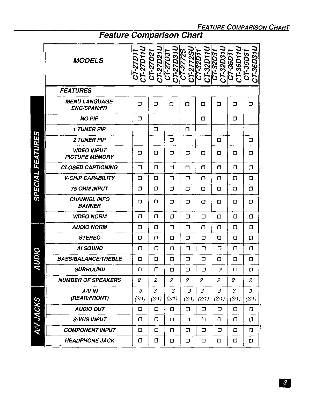
Feature Comparison Chart
MODELS
FEATURES
MENU LANGUAGE [] [] [] [] [] [] 0 []
ENG/SPAN/FR
NO PIP [] 0 []
1 TUNER PIP [3 []
2 TUNER PIP £3 [] []
VIDEO INPUT [] [] [] [] [] [] [] []
PICTURE MEMORY
CLOSED CAPTIONING [] [] [] [] [] [] [] []
V-CHIP CAPABILITY [] [] [] [] [] [] [] []
75 OHM INPUT [] [] [] [] [] [] [] []
CHANNEL INFO [] [] [] [] [] [] [] []
BANNER
VIDEO NORM [] [] [] [] [] [] [] []
AUDIO NORM [] [] [] [] £3 [] [] []
STEREO [] [] [] D 0 [] [] []
BASS/BALANCE/TREBLE [] [] [] [] [] [] [] []
M I SURROUND [] [] [] [] [] [] [] []
NUMBER OF SPEAKERS 2 2 2 2 2 2 2 2
AI SOUND [] [] [] [] [] [] [] []
(REAR/FRONT) (2/I) (2/1) (2/1) (2/1) (2/I) (2/1) (2/1) (2/1)
AUDIO OUT
S-VHS INPUT
[] [] 0 £3 [] [] []
[] [] 0 [] [] [] [] []
COMPONENT INPUT
HEADPHONE JACK
A/V IN 3 3 3 3 3 3 3 3
[] [] [] [] [] [] []
[] [] [] [] [] [] [] []
[]
CONGRA TULA TIONS
Congratulations
Your new TV features a solid state chassis that is designed to give you many years of
enjoyment. It was thoroughly tested and tuned at the factory for best performance.
Customer Record
The model and serial number of this product are located on the back of the TV. You
should note the model and serial number in the space provided and retain as a
permanent record of your purchase. This will aid in identification in the event of theft or
loss. Product registraton for U.S. customers is available at: www.prodreg.com/
panasonic.
Care and Cleaning
Model
Number
Serial
Number
Screen (Turn TV Off)
£3 Use a mild soap solution or window cleaner with a soft clean cloth. DO NOT USE
ABRASIVE CLEANERS.
[] Avoid excessive moisture and wipe dry.
Note: Do not spray any type of c/eaning fluid directly on the screen.
Cabinet and Remote Control
rl For cabinets and remote control, use a soft cloth dampened with water or a mild detergent
solution. Avoid excessive moisture and wipe dry.
[] Do not use benzene, thinner or other petroleum based products.
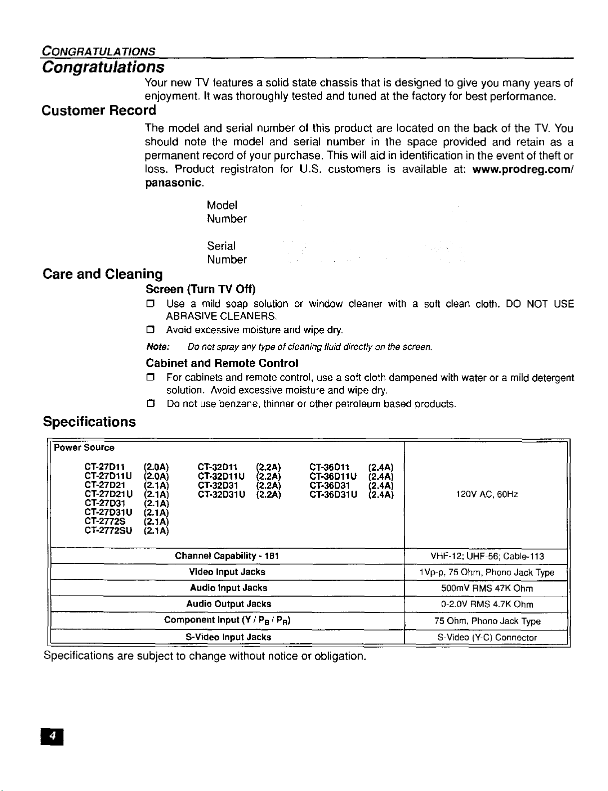
Specifications
Power Source
CT-27D11 (2.0A) CT-32D11 (2.2A) CT-36D11 (2.4A)
CT-27D11U (2.0A) CT-32D11U (2.2A) CT-36D11U (2.4A)
CT-27D21 (2.1A) CT-32D31 (2,2A) CT-36D31 (2.4A)
CT-27D21U (2.1A) CT-32D31U (2.2A) CT-36D31U (2.4A)
CT-27D31 (2.1A)
CT-27D31U (2.1A)
CT-2772S (2,1A)
CT-2772SU (2.1A)
Channel Capability - 181 VHF-12; UHF-56; Cable-113
Video Input Jacks 1Vp-p, 75 Ohm, Phono Jack Type
Audio Input Jacks 500mV RMS 47K Ohm
Audio Output Jacks 0-2.0V RMS 4.7K Ohm
Component Input (Y / PB / PR) 75 Ohm, Phono Jack Type
S-Video Input Jacks S-Video (Y-C) Connector
Specifications are subject to change without notice or obligation.
120V AC,60Hz
[]
Installation
Television Location
This unit is intended to be used with an optional stand or entertainment center.
Consult your dealer for available options.
O Avoid excessive sunlight or bright lights, including reflections.
[] Keep away from excessive heat or moisture, inadequate ventilation may cause internal
[] Fluorescent lighting may reduce remote control transmitting range.
[] Keep away from magnetic equipment, including motors, fans and external speakers.
CAUTION: Use this television receiver only with the cart, stand, tripod,
bracket, or table specified by the manufacturer, or sold with the apparatus. When
a cart is used, use caution when moving the cart/apparatus combination to avoid
injury from tip-over. In order to avoid injury to children, never place your
television receiver on a piece of furniture that is capable of being tilted by a child
leaning on it, pulling on it, standing on it, or climbing on it.
CT-27D 1l/U, CT-27D2 l/U, CT-27D3 l/U, CT-2772S/U:
CAUTION: This television receiver for use only with PANASONIC TY-27G22M stand.
Use with other carts (or stands) is capable of resulting in instability causing possible
injury.
INSTALLA TION
component failure.
CT-32D11/U, CT-32D31/U:
CAUTION: This television receiver for use only with PANASONIC TY-32G22M stand.
Use with other carts (or stands) is capable of resulting in instability causing possible
injury,
CT-36D11/U, CT-36D31/U:
CAUTION: This television receiver for use only with PANASONIC TY-36G22M stand.
Use with other carts (or stands) is capable of resulting in instability causing possible
injury.
[]
INSTALLATION
Optional Cable Connections
Shielded audio and video cables should be used between components• For best
results:
[] Use 75-ohm coaxial shielded cables.
[] Use appropriate input and output connectors, that match your component connectors.
[] Avoid long cables to minimize interference.
AC Power Supply Cord
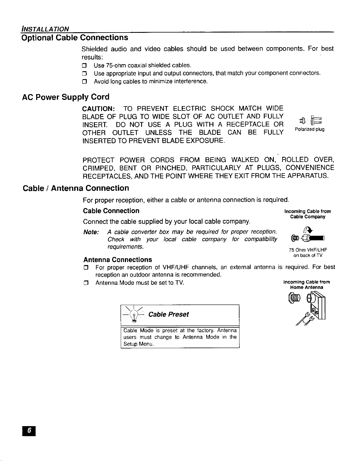
CAUTION: TO PREVENT ELECTRIC SHOCK MATCH WIDE
BLADE OF PLUG TO WIDE SLOT OF AC OUTLET AND FULLY
INSERT. DO NOT USE A PLUG WITH A RECEPTACLE OR
OTHER OUTLET UNLESS THE BLADE CAN BE FULLY
INSERTED TO PREVENT BLADE EXPOSURE.
PROTECT POWER CORDS FROM BEING WALKED ON, ROLLED OVER,
CRIMPED, BENT OR PINCHED, PARTICULARLY AT PLUGS, CONVENIENCE
RECEPTACLES, AND THE POINT WHERE THEY EXIT FROM THE APPARATUS•
Cable / Antenna Connection
Polarized plug
For proper reception, either a cable or antenna connection is required.
Cable Connection Incoming Cable from
Connect the cable supplied by your local cable company.
Note: A cable converter box may be required for proper reception.
Check with your local cable company for compatibility
requirements.
Cable Company
75 Ohm VHF/UHF
on back of TV
Antenna Connections
[]
For proper reception of VHF/UHF channels, an external antenna is required. For best
reception an outdoor antenna is recommended.
[]
Antenna Mode must be set to TV. IncomingCablefrom
__(L./
_ _ Cable Preset
Cable Mode is preset at the factory. Antenna
users must change to Antenna Mode in the
Setup Menu.
Home Antenna
[]
Optional Equipment Connections
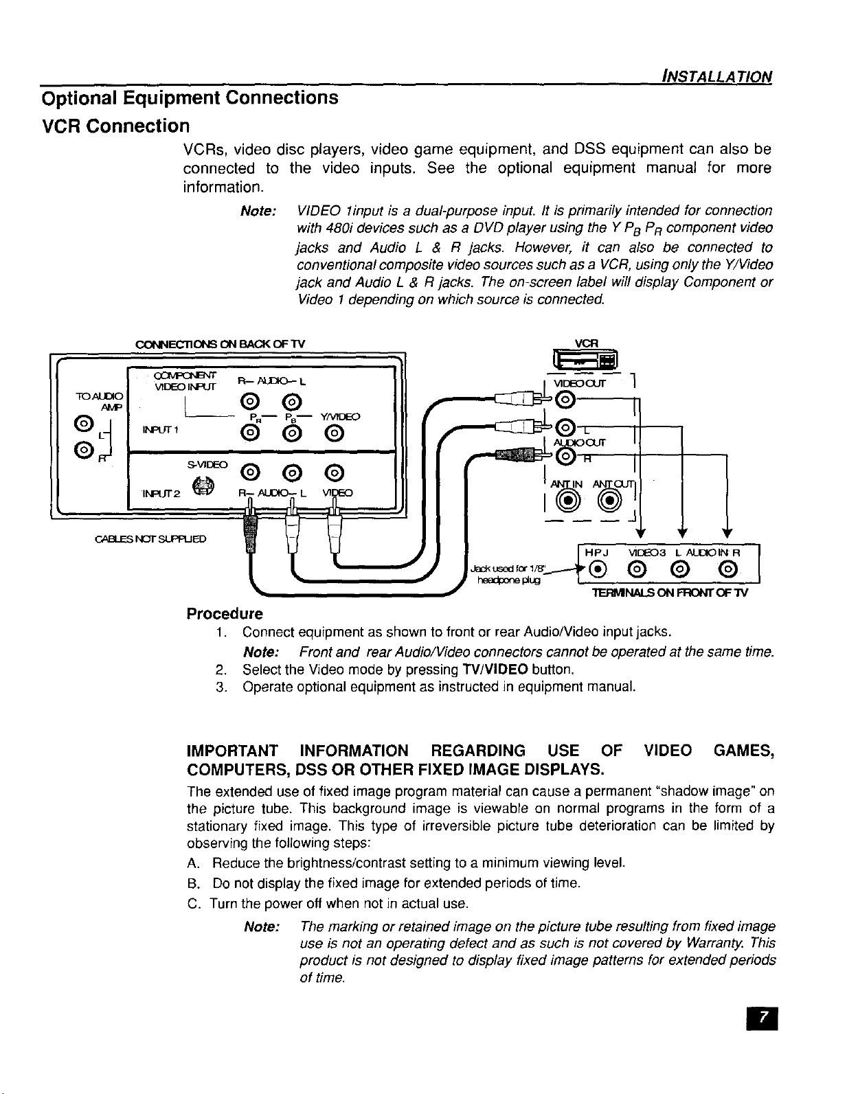
VCR Connection
VCRs, video disc players, video game equipment, and DSS equipment can also be
connected to the video inputs. See the optional equipment manual for more
information.
INSTALLA TION
CONNECTIONS ON BACKOF TM
o_ R-- AL_ L
TOAU_O
AMP
c_ NC_-SUPPIJED
VIDEO INPUT
INPUT2 _ F ,_ L VIDEO
Note:
VIDEO 1input is a dual-purpose inpuL It is primarily intended for connection
with 480i devices such as a DVD player using the Y PB PR component video
jacks and Audio L & R jacks. However, ff can also be connected to
conventional composite video sources such as a VCR, using only the Y/Video
jack and Audio L & R jacks. The on-screen label will display Component or
Video 1depending on which source is connected.
VCR
L ® @
P.-- PB-- y_DEO
® @ ®
I
HF_J VI[_--'(_3 L AUDIOIN R I
headpone_ug
Procedure
1. Connect equipment as shown to front or rear Audio/Video input jacks.
Note: Front and rear Audio/Video connectors cannot be operated at the same time.
2. Select the Video mode by pressing TV/VIDEO button.
3. Operate optional equipment as instructed in equipment manual.
I
TE_NALS ONFRONTOF3"V
IMPORTANT INFORMATION REGARDING USE OF VIDEO GAMES,
COMPUTERS, DSS OR OTHER FIXED IMAGE DISPLAYS.
The extended use of fixed image program material can cause a permanent "shadow image" on
the picture tube. This background image is viewable on normal programs in the form of a
stationary fixed image. This type of irreversible picture tube deterioration can be limited by
observing the following steps:
A. Reduce the brightness/contrast setting to a minimum viewing level.
B. Do not display the fixed image for extended periods of time.
C. Turn the power off when not in actual use.
Note: The marking or retained image on the picture tube resulting from fixed image
use is not an operating defect and as such is not covered by Warranty. This
product is not designed to display fixed image patterns for extended periods
of time.
[]
 Loading...