

Panasonic CT-3696VY-1 User Manual

Panasonic
Operating Instructions
CT- 3696VY-1
For additional information about Panasonic products, visit our Internet site on the
World Wide Web at:
Read these instructions completely before operating.
Contents subject to change without notice or obligation.
Copynght 1999 by Matsushita Electric Corporation
of America. All nghts reserved. Unauthorixed
copying and distribution is a violation of law.
www.panasonic.com
Printed in U.S.A.
TQB2AA0279

Table of Contents
Specifications
Safety Instructions
Introduction
......................................................
...............................................
..........................................................
3
4
6
Average Power Consumption ............................... 6
Important Information
FCC Statement
FCC Caution
Installation
.....................................................
............................................................
...........................................
.................................................
7
7
7
8
Television Location............................................ 8
Optional External Equipment Connections
AC Power Supply Cord
Remote Control Battery Installation
TV Antenna/Cable Connections
Other Video Equipment
.....................................
...................
........................
......................................
........
8
8
8
9
9
Care And Cleaning............................................ 9
Location of Controls (TV/Monitor)
Quick Reference Control Operation
........................
.................
10
10
Location Of Control For The Home Theater Remote
Unit .............................................................. 11
Basic Remote Control Functions
......................
11
Remote Control Quick Reference Functional
Key Chart.......................................................12
Special Functions
Multi Button
...............................................
.......................................................
14
14
Recall Button..................................................... 14
R-Tune (Rapid Tune) Button............................. 14
Optional Equipment Connection and Operation . 15
Stereo Connection (To Audio AMP) ................. 15
Video/Audio Connection
..................................
15
TV MODE
Trilingual Animated Icons
TV Mode Icons...............................................16
Menu Language Selection.................................16
Picture Adjustments
Picture Norm
................................................
Color, Tint, Brightness, Picture and
Sharpness Adjustments ............................. 16
Color Temp.................................................... 17
Auto Color
Video NR
....................................................
......................................................
Audio Adjustments ............................................18
Audio Norm ................................................. 18
Bass, Treble and Balance
Mode - Stereo/SAP/Mono ........................... 18
Speaker ........................................................ 19
Surround ....................................................... 19
Al Sound ....................................................... 19
TV/PC/DTV........................................................20
Set Up Features
Clock Auto
...............................................
....................................................
Clock Manual ...............................................22
Set Day
.........................................................
..................................
..........................................
..........................
16
16
16
17
17
18
20
20
22
Auto Power On
Geomagnetic Corr (Correction)
Mode ...........................................................................23
Auto Program
Manual Program ........................................................24
Closed Caption On Mute
Closed Caption Mode
Timer Features ...............................................................26
Sieep Timer.................................................................26
Program Timer
Input Select
Favorite Channel
Channel Scan
Favorite Channel Select
Channel Caption..............................................................28
Preset Caption
Manual Caption ..........................................................29
Lockout Features
Lockout Mode
Unlock ........................................................................31
Control Panel Lock Feature ..........................................31
Programming the Home Theater Remote .......................32
Infrared Remote Codes For Components................32
VCR Infrared Codes index
Cable Box and CD Players
Infrared Codes Index
Cassette Players, Receivers, and Amplifiers
Infrared Codes Index
Laser Disc, DSS, and DVD
Infrared Codes Index
.............................
............................................;..............
...........................................
.................................................
...........................................................
.....................................................................
............................................................
..............................................................
............................................
...........................................................
............................................................
.............................................................
...............................................
.................................................
................................................
................................................
.............................22
............
....................23
PC MODE
PC Input Connection (Rear)...........................................37
PC Input Connection (Front)..........................................38
TV/PC/DTV
Trilingual Animated Icons ..............................................39
PC Mode Icons
Picture Adjustments.......................................................39
Picture Norm...............................................................39
Color, Tint, Brightness, Picture and
Color Temp ................................................................40
Audio Adjustments.........................................................40
Audio Norm.................................................................40
Bass, Treble and Balance..........................................40
Speaker
Surround ....................................................................41
Al Sound
Set Up Features
Auto Power On
Geomagnetic Corr (Correction)
Input Select ....................................................................42
Display Adj .....................................................................43
Display Adjust Chart .................................................43
2-
.......................................................................
..........................................................
Sharpness Adjustments.........................................39
.......................................................................
....................................................................
.............................................................
...........................................................
................................
24
25
25
26
27
27
27
28
28
30
30
33
34
35
36
39
39
41
41
42
42
42

Table of Contents (cont.)
DTV MODE
Components Video Connection.......................44
TV/PC/DTV
Trilingual Animated Icons
DTV Mode Icons
Picture Adjustments.......................................................45
.......................................................................
.............................................
.........................................
Picture Norm............................................... 45
Color, Tint, Brightness, Picture and
Sharpness Adjustments
Color Temp
Audio Adjustments.........................................................46
Audio Norm
................................................
..................................................
............................
Bass, Treble and Balance............................46
Specifications
Power Source:
Channel Capability:
Video Input Jacks (2):
Audio Input Jacks (2):
To Audio Amp Jacks:
S-Video Input Jack (2):
DTV Input Jacks:
Stereo Sound:
Surround Sound:
120V ac, 60Hz
181 channels (See chart)
VHF2-13, UHF 14^-69.
Cable 125 channels
IV p-p, 75 ohm, phono jack type
500mV rms, 47K ohm
0-2.0V rms 4.7K ohm
S-Video (Y-C) Connector
Component Video (Y, ft , Bt )
NTSC with DBX Noise Reduction
Matrix
45
45
45
45
46
46
Speaker
Surround
Al Sound
Set Up Features ...............................................................48
Auto Power On
Aspect Ratio
Color Matrix
Geomagnetic Corr (Correction)
........................................................
......................................................
......................................................
............................................
.................................................
..................................................
....................
TROUBLESHOOTING
Troubleshooting Chart
Computer Resolution Set Up For Windows 95 . 50
Computer Resolution Set Up For Windows 3.X . 51
......................................................
Channel Capability Chart
......
....
CHANNELS
VHF 12
UHF 56
CABLE (Mid-Band)
CABLE (Super Band)
CABLE (Hyper Band)
CABLE (Ultra Band)
TOTAL CHANNELS
15
14
28
56
181
47
47
47
48
48
48
48
49
Computer Monitor Specifications
PC and Mac Compatible
Viewable Image Size
Dot Pitch
Multi-scan Rate
Horizontal Frequency Range
Vertical Frequency Range
Max. Data Resolution
Linearity Correction
S-Curve Correction
Dynamic Astigmatism and
Focus Correction
Audio Input-computer
Computer Input
Yes
36.0 inches
Data Grade
Yes
15 kHz to 38 kHz
50 Hz to 120 Hz
800 x 600 @ 60 Hz
Automatic
Yes
Yes
Mini-jack on front panel
2-Front and rear 15-pin connector
Signal Capability Chart
Signal Format
NTSC
VGA 640 X 480
VGA text
VGA 640 X 480
SVGA 800 X 600
MAC2 640 X 480
Specifications are subject to change without notice or obligation.
Horiz.
31.5
31,5 kHz 70 Hz
31.5
37.9 kHz
35
notice
Freq.
15.75
kHz 60
kHz
kHz
kHz
or obligation.
Vert. Freq
Hz Ir
70 Hz
Hz
60
Hz
60
Hz
66.6
-3-
Safety Instructions
WARNING
RISK OF ELECTRIC SHOCK
DO NOT OPEN
WARNING: To reduce the risk of electric shock do not remove cover or back. No
user-serviceable parts inside. Refer servicing to qualified service personnel.
The lightning flash with
arrow-head within a triangle
is intended to tell the user
that parts inside the product
are a risk of electric shock to
persons.
A
The exclamation point within
a triangle is intended to tell the
user that important operating
and servicing instructions are
in the papers with the
appliance.
Note To CATV System Installer; This reminder is provided to direct the CATV system installer’s attention to Article
820-40 of the NEC that provides guidelines for proper grounding and, in particular, specifies that the cable ground shall be
connected to the grounding system of the building, as close to the point of cable entry as practical.
Safety Instructions For Television Receivers
1. Read and apply the operating instructions provided with your television receiver.
2. Read all of the instructions given here and retain them for later use.
3. Unplug this television receiver from the wall outlet before cleaning.. Do not use liquid or aerosol cleaners. Use a damp
cloth for cleaning.
4. Do not use attachments not recommended by the television receiver manufacturer as they may cause hazards.
5. Do not use this television receiver near water. For example: Avoid placing it near a bathtub, washbowl, kitchen sink, or
laundry tub, in a wet basement, or near a swimming pool, etc.
6. Do not place this television receiver on an unstable cart, stand or table. The television receiver may fall, causing serious
injury to a child or adult, and serious damage to the appliance. Use only with a cart or stand recommended by the
manufacturer, or sold with the television receiver. Wall or shelf mounting should follow the manufacturer's instructions,
and should use a mounting kit approved by the manufacturer.
6A. An appliance and cart combination should be moved with care. Quick stops, excessive force, and
uneven surfaces may cause the appliance and cart combination to overturn.
7. Slots and openings in the cabinet and the back or bottom are provided for ventilation, and to insure
reliable operation of the television receiver and to protect it from overheating. These openings must not be blocked or
covered. The openings should never be blocked by placing the television receiver on a bed, sofa, rug or other similar
surface. This television receiver should never be placed near or over a radiator or heat register. This television receiver
should not be placed In a built-in installation such as a bookcase unless proper ventilation is provided.
8. Operate only from the type of power source indicated on the marking label. If you are not sure of the type of power
supplied to your home, consult your television dealer or local power company. For television receivers designed to
operate from battery power, refer to the operating instructions.
9. This television receiver is equipped with a polarized alternating-current line plug (a plug having one blade widerthan the
other). This plug will fit into the power outlet only one way. This is a safety feature. If you are unable to insert the plug
fully into the outlet, try reversing the plug. If
the plug should still fail to fit, contact your
electrician to replace your obsolete outlet. Do
not defeat the safety purpose of the polarized
plug.
10. Do not allow anything to rest on the power
cord. Do not locate this television receiver
where the cord will be damaged by people
walking on it.
11. Follow all warnings and instructions marked
on the television receiver.
12. Do not overload wall outlets and extension
cords as this can result in fire or electric
shock.
13. Never push objects of any kind into this
television receiver through cabinet slots as
they may touch dangerous voltage points or
short out parts that could result in a fire or
electric shock. Never spill liquid of any kind on
the television receiver.
-4-

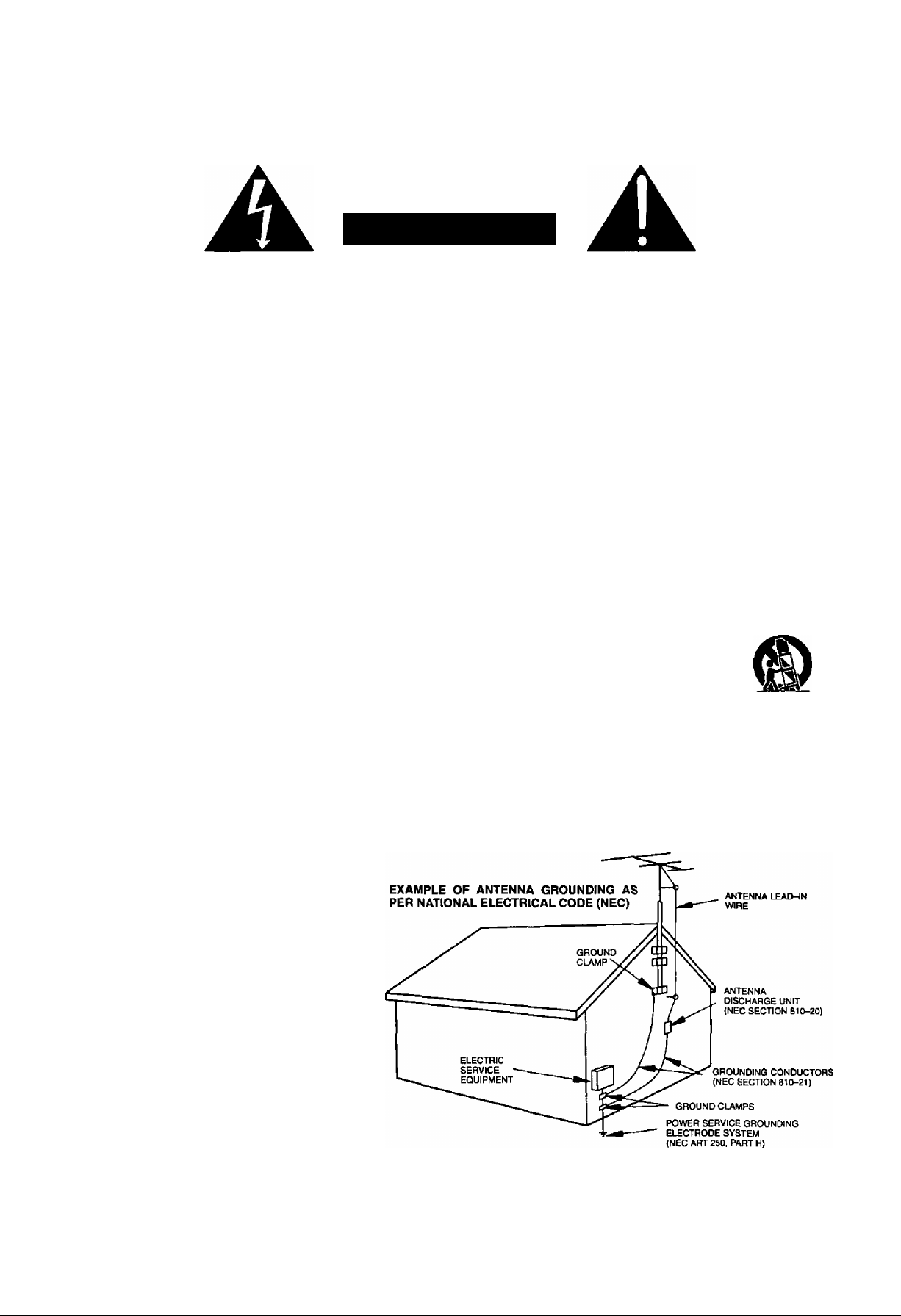
14. If an outside antenna is connected to the television equipment, be sure the antenna system is grounded so as to provide
some protection against voltage surges and built up static charges. In the U.S. Section 810 of the National Electrical
Code and in Canada Part 1 of the Canadian Electrical Code provides information with respect to proper grounding of the
mast and supporting structure, grounding of the lead-in wire to an antenna discharge unit, size of grounding conductors,
location of antenna-discharge unit, connection to grounding electrodes, and requirements for the grounding electrode.
See Figure.
15. For added protection for this television receiver during a lightning storm, or when it is left unattended and unused for long
periods of time, unplug it from the wall outlet and disconnect the antenna. This will prevent damage to the receiver due to
lightning and power-line surges.
16. An outside antenna system should not be located in the vicinity of overhead power lines or other electric light or power
circuits, or where it can fall into such power lines or circuits. When installing an outside antenna system extreme care
should be taken to keep from touching such power lines or circuits as contact with them might be fatal.
17. Unplug this television receiver from the wall outlet, and refer servicing to qualified service personnel under the following
conditions:
a. When the power cord or plug is damaged or frayed.
If liquid has been spilled into the television receiver.
b.
If the television receiver has been exposed to rain or water.
c.
If the television receiver does not operate normally by following the operating instructions. Adjust only those controls
d.
that are covered by the operating instructions as improper adjustment of other controls may result in damage and will
often require extensive work by a qualified technician to restore the television receiver to normal operation.
If the television receiver has been dropped or the cabinet has been damaged.
e.
When the television receiver exhibits a distinct change in performance - this indicates a need for service.
f.
18. Do not attempt to service this television receiver yourself as opening or removing covers may expose you to dangerous
voltage or other hazards. Refer all servicing to qualified service personnel.
19. When replacement parts are required, be sure the service technician has used replacement parts specified by the
manufacturer that have the same characteristics as the original part. Unauthorized substitutions may result in fire,
electric shock, or other hazards.
20. Upon completion of any service or repairs to this television receiver, ask the service technician to perform routine safety
checks to determine that the television is in safe operating condition.
21. WARNING: To prevent fife or shock hazard, do not expose this appliance to rain or moisture.
22. CAUTION: TO PREVENT ELECTRIC SHOCK DO NOT USE THIS (POLARIZED) PLUG WITH A RECEPTACLE OR
OTHER OUTLET UNLESS THE BLADES CAN BE FULLY INSERTED TO PREVENT BLADE EXPOSURE.
NOTE: This equipment is designed to operate in the U.S.A., Canada and other countries where the broadcasting system and
AC house current is exactly the same as in the U.S.A. and Canada.
Important Information Regarding Use of Video Games, Computers, Teletext or Other Fixed Image Displays.
The extended use of fixed image program material can cause a permanent “shadow image” on the picture tube. This
background image is viewable on normal programs in the form of a stationary fixed image. This type of irreversible picture
tube deterioration can be limited by observing the following steps:
A. Reduce the brightness/contrast setting to a minimum viewing level.
B. Do not display the fixed image for extended periods of time.
C. Turn the power off when not in actual use.
NOTE: The marking or retained image on the picture tube resulting from fixed image use is not an operating defect and as
such is not covered by Warranty. This product is not designed to display fixed image patterns for extended periods of
time.
-5-

Congratulations on Your New Purchase
Your new Monitor features an all solid state chassis which is designed to give you many years of enjoyment. It was thor
oughly tested and adjusted at the factory for best performance.
In order for you to take full advantage of your new Monitor, please read and follow the installation and operating instructions
contained herein.
Customer’s Record
The model and serial number of this product may be found on its back cover. You should note the model and serial number
in the space provided and retain this book as a permanent record of your purchase to aid in identification in the event of
theft or loss.
Model Number: Serial Number:
Technical Support or Service Center information for your Monitor is available on the
Internet at:
For Technical Assistance; Call 800-524-1448, Monday-Friday (9 a.m-5 p.m EST), For your locai Service Center: Call 800-526-6610.
www.panasonic.com or E-Mail at: pbtssupport@panasonic.com
Average Power Consumption
TV Mode
VGA
Mode
SVGA
Mode Mode
180W 170W 175W
-6-
Standby
1.7W
IMPORTANT INFORMATION
FCC STATEMENT:
This equipment was tested and found to comply within the
limits for a Class B digital device, pursuant to Part 15 of
the FCC rules. These limits are designed to provide
reasonable protection against harmful interference in a
residential installation.
This equipment generates, uses and can radiate radio
frequency energy and, if not installed and used in
accordance with the instructions, may cause harmful
interference with radio communications. However, there
is no guarantee that interference will not occur in a
particular installation. If this equipment does cause
harmful interference to radio or television reception, which
can be determined by tuning the equipment on and off, the
user is encouraged to try to correct the interference by one
or more of the following measures:
• Reposition or relocate the receiving antenna.
• Increase the separation between the equipment and
radio/TV receiver.
• Connect the equipment into an outlet on a circuit
different from that to which the radio/TV is connected.
• Consult the dealer or an experienced radio/TV
FCC CAUTION:
Pursuant to 47CFR, Part 15.21 of the FCC rules, any
changes or modifications to this monitor not
expressly approved by Matsushita Electric
Corporation of America couid cause harmfui
interference and wouid void the user’s authority to
operate this device.
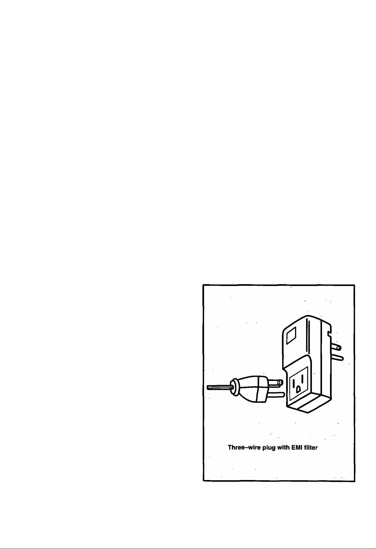
To assure continued compliance, the shielded video
cable with bonded ferrite cores provided must be
used when connecting this TV to a computer device.
(Part # TSX4515-3). The TDK EMI filter, also provided.
Part #ANF-106U, must be used to plug this TV into a
grounding type outlet
CANADIAN NOTICE:
This class B digital apparatus meets all requirements
of the Canadian Interference-Causing Equipment
Regulations.
AVIS CANADIEN:
Cet appareil numérique de ia classe B respecte toutes
les exigences du règlement sur le matériel brouilleur
du Canada.
technician for assistance.
Important: Changes or modifications not expressly
approved by the party responsible for compliance could
void the user’s authority to operate the equipment.
FCC Declaration of Conformity
PANASONIC BROADCAST AND DIGITAL
SYSTEMS COMPANY
Responsible party:
Division of Matsushita Electric Corporation of America
One Panasonic Way
Secaucus, NJ 07094
U.S.A.
Telephone number: 1-800-524-1448
9 a.m. to 5 p.m., M-F, EST) or
EMAIL: PBTSSUPPORT @ PANASONlC.COM
This device complies with Part 15 of the FCC rules.
Operation is subject to the following two conditions:
(1) this device may not cause harmful interference,
and (2) this device must accept any interference
received, including interference that may cause
undesired operation.
-7-
Installation
Vídeo Monitor Location
This video Monitor is intended to be used with an optionai stand. Consult your dealer for available options.
Locate for comfortable viewing. Avoid placing where sunlight or other bright light (including reflections) will fall on the screen.
Use of some types of fluorescent lighting may reduce remote control transmitter range. '
Adequate ventilation is essential to prevent internal component failure. Keep away from areas of excessive heat or moisture.
To insure optimum color purity do not position equipment containing magnets (motors, fans, external speakers, etc.) nearby.
Optional External Equipment Connections
The AudioA/ideo connections between components can be made with shielded video and audio cables. For best
performance, video cables should be of 75 ohm type coaxial shielded cables. Cables are available from your dealer or
electronic supply house.
Before you purchase any cables, check out the type of output and input connectors your various components require.
Also determine the length of cable you will need.
Power Supply Cord
MAKE SURE PLUG IS INSERTED FULLY INTO THE EMI FILTER. SEE PAGE 7
ILLUSTRATION.
This product is equipped with a three-wire grounding type plug—a plug with two blades and
a third pin which is round. This plug will only fit into a grounding type outlet.
This is a safety feature. If you are unable to insert the plug into the outlet, contact your
electrician to replace your obsolete outlet. DO NOT DEFEATTHE SAFETY PURPOSE OF
THE GROUNDING TYPE PLUG.
NOTE: Two RCA to BNC adaptor is supplied with the Monitor/Receiver.
RCA to BNC Adaptor
(supplied)
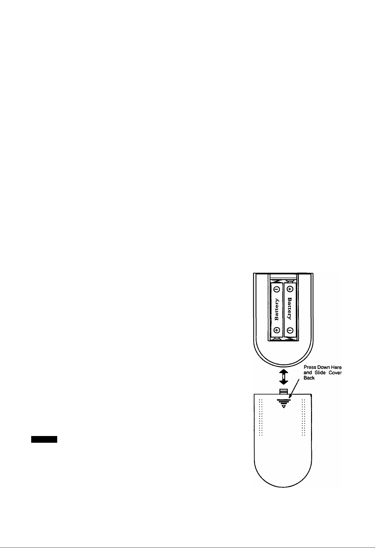
Remote Control Battery Installation
Batteries: Use two “AA” batteries.
1. Remove the battery compartment cover on back of
the remote.
2. Install the batteries in the battery compartment.
(Polarity (+) or (-) must be correct.)
3. Reattach the battery cover.
Helpful Hints:
For frequent Remote Control users, replace old batteries with
Alkaiine batteries for longer life.
Precaution on Battery Use
incorrect instaliation can cause battery leakage and corrosion
that will damage the Remote Control.
Observe the Following Precautions:
1. Batteries must be replaced as a pair.
2. Do not combine a used battery with a new one.
3. Do not mix battery types (Example: "Zinc Carbon" with "Alkaline”).
4. Do not attempt to charge, short-circuit, disassemble, heat or burn used
batteries.
5. Battery replacement is necessary when Remote Control reacts
sporadically or stops operating the television.
NOTE:
Whenever you remove the batteries to replace
them, you may need to reset the Remote Control
Infrared Codes. We recommend that you initially
record the codes in the Infrared Remote Codes for
Specific Components section, priorto setting up the
remote.
-8-
Installation (Cont)
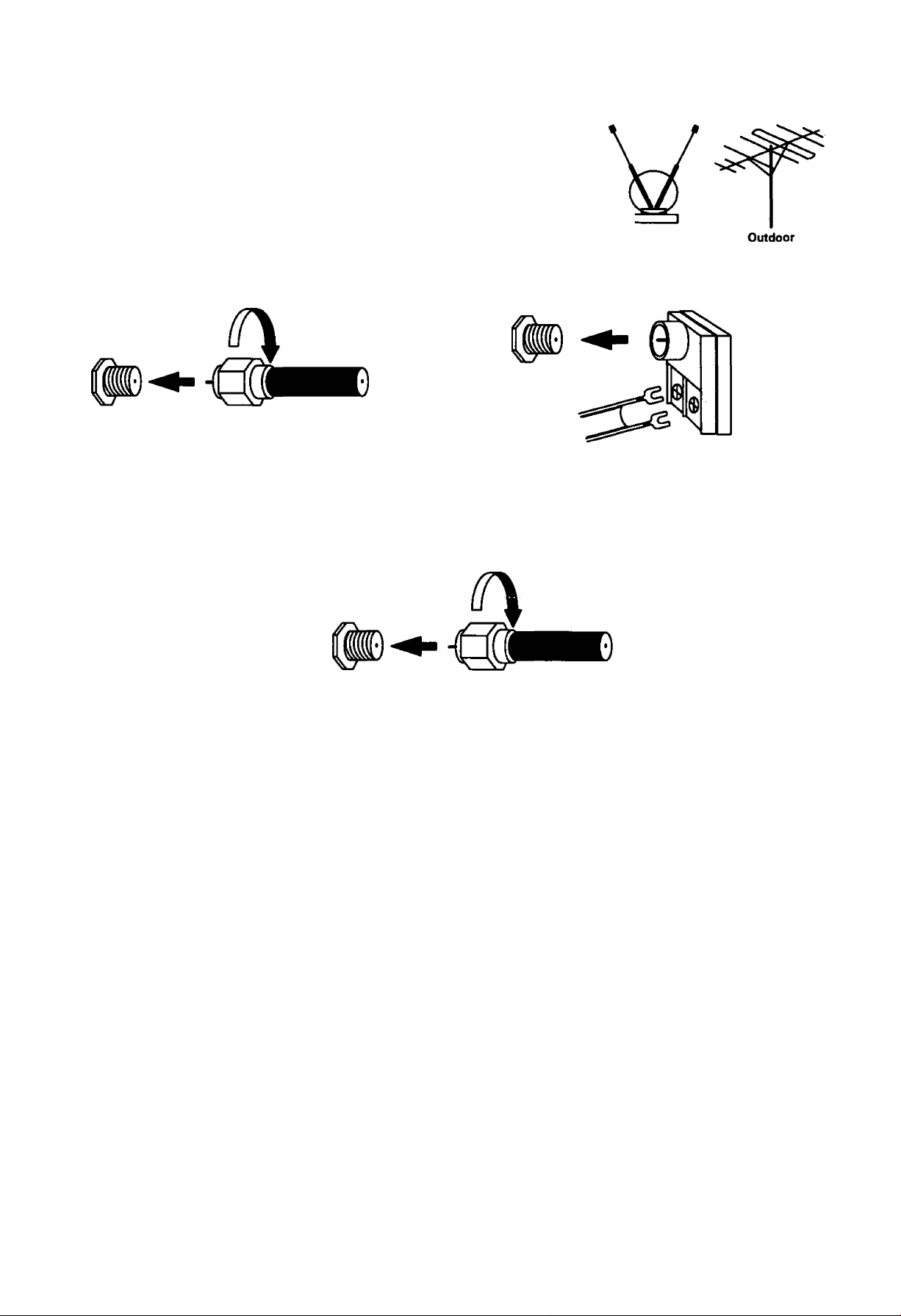
Antenna/Cable Connections
Antenna Connection - For proper reception of VHF/UHF channels, an external
antenna is required. For best reception, an outdoor antenna is recommended. In the
SETUP menu, set the MODE to TV. (Refer to Antenna Mode section.) c
Indoor
Incoming Cable from Home Antenna
Typical VHFAJHF Antenna
75 Ohm
VHF/UHF
on Back of Set
VHF/UHF „„„
on Back of Set 300 Ohm
or
300 to 75 ohm Matching
Transformer (Not Included)
Cable Connection - For reception of cable channels, connect the cable supplied by your local cable company. In the
SETUP menu, set the MODE to CABLE. (Refer to Antenna Mode section.)
Incoming Cable from Cable Company
75 Ohm
VHFAJHF
on Back of Set
NOTE: Certain cable systems offset some channels to reduce interference, or have premium (scrambled) channels. A
cable converter box is required for proper reception. Check with your local Cable company for compatibility
requirements.
Other Video Equipment
VCRs, Video Disc Players, Computers, TV games, and DSS equipment can also be connected to the antenna input
connection.
Care and Cleaning
Screen (Turn Monitor off)
Use a mild soap solution or window cleaner and a clean cloth. DO NOT USE ABRASIVE CLEANERS. Avoid excessive
moisture and wipe dry.
Plastic Cabinet
Wipe the cabinet with a soft cloth dampened with water or a mild detergent solution and wipe dry with a soft clean cloth.
Avoid excessive moisture. Do not use benzene, thinners or other petroleum-based cleaners.
Remote Control Transmitter
Use a soft cloth slightly moistened with a mild detergent and then wipe dry with a soft clean cloth. Avoid excessive
moisture. Do not use benzene, thinners or other petroleum-based cleaners.
-9-
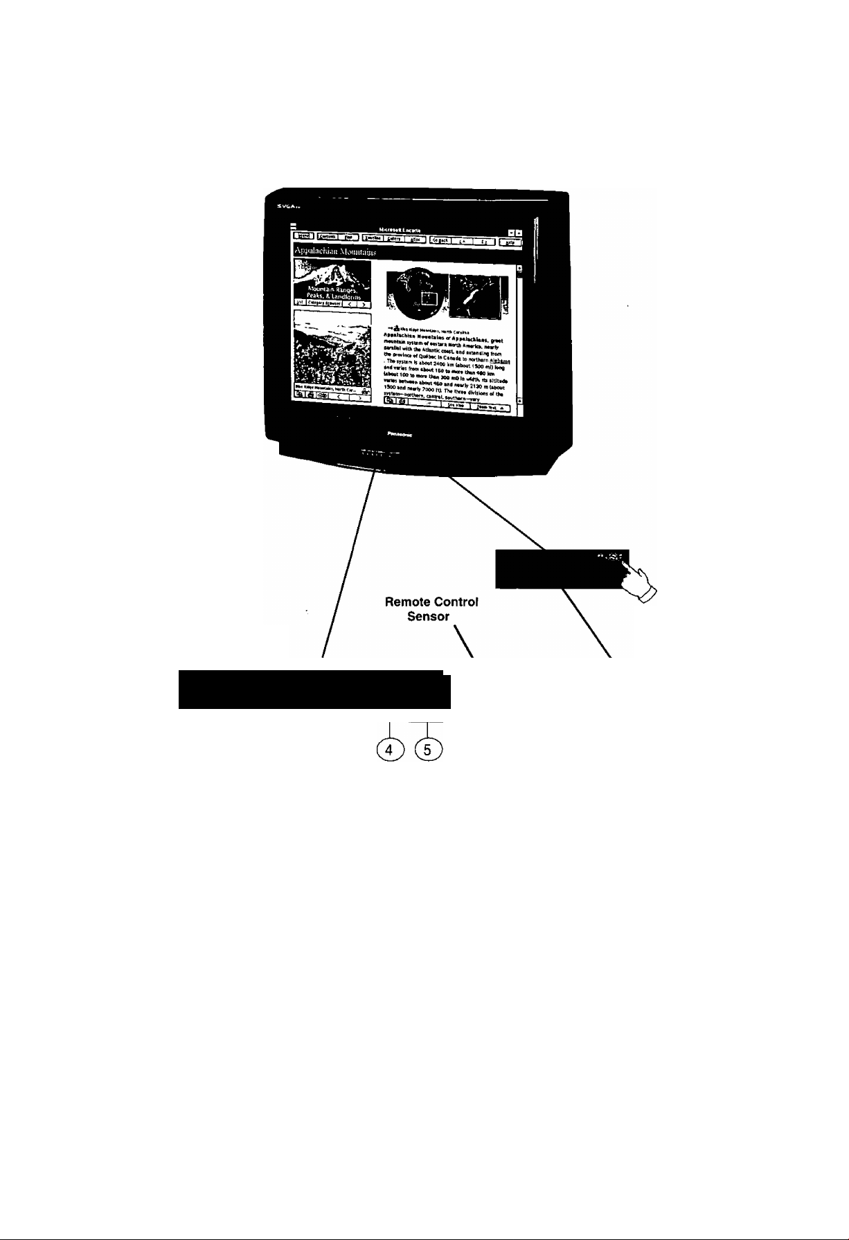
Location of Controls (TV/Monitor)
Push here to
Front Control Panel
POWER ^VOLUME^ ▼ CHANNEL^ ACTION INPUT
open door
r
o o o o o o o
Quick Reference Control Operation
(T)
Power Button - Press to turn television ON or OFF.
Volume Buttons - Press to adjust Sound Level, Audio and Video Menus and to select operating features
when menus are displayed.
(D Channel Buttons - Press to select programmed channels or to highlight desired features when menus
are displayed.
(5) Action Button - Press to display Main Menu and access or exit On Screen feature and Adjustment Menus.
(D Input Button - TV Mode press to select TV or one of two Video Inputs. PC Mode press to select Front or
Rear PC Input.
© Audio Input - Use Front PC Audio input jack when connected to a PC sound source Audio output.
® PC Input - Connect to a computer having a 15-pin output terminal.
-10-
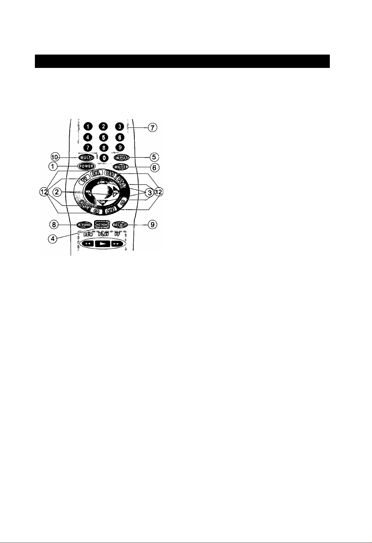
Location of Controls for the Home Theater Remote Unit
Basic Remote Control Functions
The following is a basic overview of the remote control
unit for TV/Monitor operation. Ensure the TV mode
button is selected by initially pressing .
(T) Power Button - Press to turn the TV ON or OFF.
^Volume Buttons - Press to adjust TV sound level.
Use with Channel buttons to navigate in menus.
©Channel Buttons - Press to select channels. Use
with Volume buttons to navigate in menus.
@ Action Button - Press to display Main Menu and
access or exit On-Screen feature and Adjustment
Menus.
® Input Button - Press to select TV or one of two (2)
Video Inputs. Also used to select Front or Rear PC
Input.
©Mute Button - Press to mute sound. A second
press returns sound.
©Numeric Keypad (0 through 9 Buttons) - Press
desired channel to access any channel.
0 ms
" ^ 'IRi
® R-Tune (Rapid Tune) Button - Switches between
two (2) channels.
@ Recall Button - Press to display Time, Status or
Sleep Timer, Channel, Video Mode, Channel
Caption (Station Identifier), and Audio Mode.
Home Theater
Remote Control
TNQ2AE012
©Multi Button - Programmable to operate up to six
(6) Remote Function buttons simultaneously.
©VCR Functions Buttons - Programmable to
operate many brands of VCR’s.
©Mode Selection Buttons - Selects the operations
mode for the remote control.
©VCR/DSS Channel Buttons - These buttons are
used to select VCR or DSS channels (Up/Down).
Helpful Hints:
If the selected component does not respond to the
remote control, ensure that the proper mode is
selected. First, press the Mode Selection Button
that corresponds to that component. For example,
after first pressing the TV mode button, the remote
will remain in the TV mode for any following
commands. If a different mode button is pressed
while operating the television, the TV mode button
must be pressed again to reset the TV mode
condition.
-11 -

Remote Control
Quick Reference Functional Key Chart
KEY MODE FUNCTION
© © (3)
© © ©
© © ®
©
(MUL^
(INP^
gPQW^
(MUTE)
TV
VCR, VCR 2
CABLE, DSS
RECEIVER/AMPLIFIER
CD PLAYER
LD PLAYER
ALL COMPONENTS
TV
ALL COMPONENTS
TV, DSS, VCR, VCR 2 LDP
CABLE
RECEIVER/AMPLIFIER
TV
Selects Channel
Selects Channel
Selects Channel
© Selects Tuner
® Selects CD Player
® Selects Tape Cassette Player
® VCR 1
® VCR 2
Selects Track Number
Selects Track Number
Programmable Button That Can Operate Up To Six (6) Remote
Functions At Once
Select the TV Input Mode
Also Selects Front or Rear PC Input
Turns On and Off Selected Components
Mutes TV Audio
Mutes Audio
Mutes Audio
TV Mode Selection for Remote Control
css3
Qid
CABLE
DSS {DIGITAL SATELLITE
SYSTEM)
VCR
RECEIVER/AMPLIFIER
COMPACT DISC
CASSETTE DECK,
VCR 2, DVD
LASER DISC PLAYER
TV
CABLE
DSS
LDP
CD
RECEIVER/AMPLIFIER
DVD
TV
CABLE
DSS
RECEIVER/AMPLIFIER
VCR, VCR 2
LDP
Cable Mode Selection for Remote Control
DSS Mode Selection for Remote Control
VCR Mode Selection for Remote Control
Receiver/Amplifier Mode Selection for Remote Control
CD Mode Selection for Remote Control
AUX Mode Selection for Remote Control
Enables User to Operate a Cassette Deck, Digital Video Disc or
Second VCR
LD Mode Selection for Remote Control
Channel Up/Down, Menu Navigation
Channel Up/Down
DSS Guides and Menu Navigation
Skip
FF, REW
Preset or Tuning Frequency
Skip FWD/Skip REW
Volume Up/Down, Menu Navigation
Volume Up/Down
DSS Guides and Menu Navigation
Volume Up/Down
TV Volume Up/Down
TV Volume Up/Down
-12-

Remote Control
Quick Reference Functional Key Chart (cont’d.)
(R-TUNE)
^lACTIOtj]
REW
PLAY
[>-
MODE
LDP
TV
CABLE
VCR, VCR 2
DSS
RECEIVER/AMPLIFIER
CD
AUTO TAPE RECORDER
TV
DSS
TV
DSS
VCR, VCR 2
LDP
DSS
VCR, VCR 2
LDP
TAPE
CD
DVD
DSS
VCR, VCR 2
LDP
TAPE
CD
DVD
FUNCTION
A/B Repeat
Switches Between Two (2) Channels
Switches Between Two (2) Channels
Switches Between Two (2) Channels
Switches Between Two (2) Channels
Switches Between AM and FM
Selects Next Disc
Selects Audio Tape Recorder A or B
Activates TV Menus
Acts as Menu Button for DSS
Displays Channel, Sleep Time, Channel Caption, Time and
Audio Mode
Displays Current DSS Settings
Displays Current VCR Settings
Displays Current LDP Settings
DSS Guide
Rewind
Rewind
Rewind
Selects Previous Track
Rewind
Enter/Select
Play
Play
Play (in Normal Direction)
Play
Play
FF
REC
STOP
PAUSE
TV/VCR
o
VCR/DBS CH
DSS
VCR, VCR 2
LDP
TAPE
CD
DVD
DSS
VCR, VCR 2
TAPE
CABLE
DVD
VCR, VCR 2
LDP
TAPE
CD
CABLE
DVD
VCR, VCR 2
LDP
TAPE
CD
CABLE
VCR, VCR 2
DSS
CABLE
VCR, VCR 2
DSS
Exit/Clear
Fast Forward
Fast Forward
Fast Fonward
Selects Next Track
Fast Fonward
One Touch Record in DSS Mode
Record
Record
VCR Record
Stop
Stop
Stop
Stop
Stop
VCR Stop
Pause
Pause
Pause
Pause
Pause
VCR Pause
Selects TVA/CR Mode
Selects TV/DSS Mode
Selects TVA/CR Mode
Channel Up/Down
Channel Up/Down
-13-
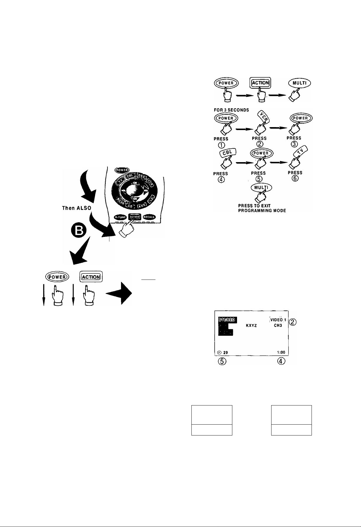
Special Functions
MULTI Button
The MULTI Button can be programmed to issue
several commands at the same time.
Example; TV Power/On, VCR Power/ON, and Cable
Box Power/On.
Procedure:
1. Enter proper infrared codes for all devices before
programming. See code section.
2. Point your Remote Control Transmitter away from
all equipment remote sensors, then:
The following is a flow chart example of remote
functions that can be programmed into the
button:
PRESS AT THE SAME TIME
PRESS
Press and
keep holding
Release after 3
seconds
Li^©.©!
Press and keep
holding for 3
seconds
(mul^
Press
Pressing the cmultp» button will now activate the VCR
Power/On, Cable Box Power/On, and the Receiver
Power/On at the same time.
RECALL Button
Press the RECALL Button to review:
(T) Audio Mode status
CH number or Video Input selected
Channel Caption (Station Identifier)
Clock time
Sleep Timer status
© ®
0
NOTE: Waiting more than 30 seconds without pressing
another button will exit the programming mode.
3. Press a maximum of 6 function buttons on the
Remote Control. Each button you press is equal to
one function. If 6 Remote button functions are
entered, all will register in the button
memory when the sequence is entered. When
finished, press the cmultP' to exit the programming
mode.
NOTE: Buttons which continuously perform a function
as long as pressed (Volume Up/Down, Channel
Up/Down, etc.) cannot be programmed; only those
buttons which perform a function when initially
pressed {Power On/Off, Mute, Direct Channel
Entry, etc.) can be programmed.
-14-
R-TUNE Button
Pressing the R-TUNE (RAPID TUNE) button toggles to
the previously tuned program.
PROGRAM
CURRENTLY VIEWED
Press Button
Press Button Again
PROGRAM
PREVIOUSLY VIEWED
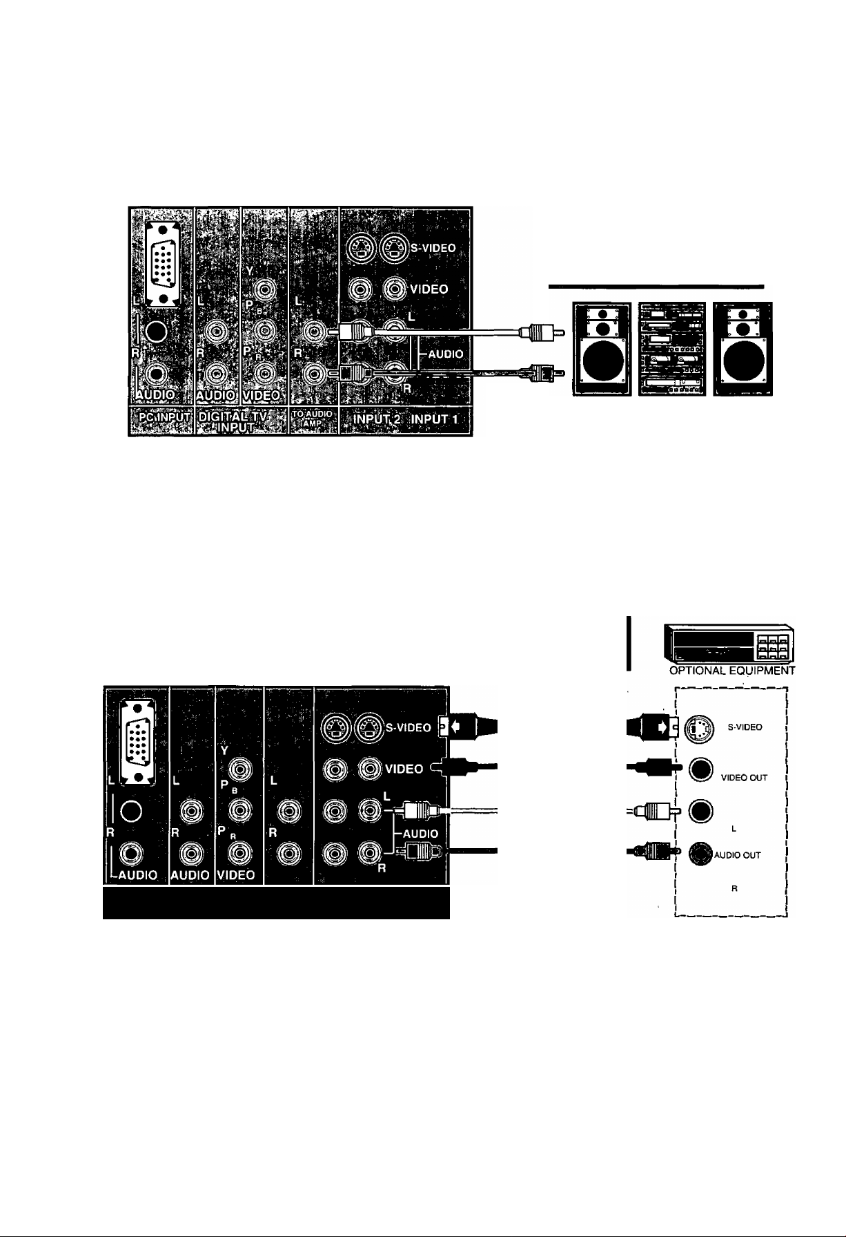
Optional Equipment Connection and Operation
To Audio AMP Connection (Stereo)
Connect to an external audio amp auxiliary input for monitoring sound through a stereo system.
TERMINALS ON BACK OF MONITOR
“TO AUDIO AMP” terminals
cannot be used directly with
external speakers.
(Connecting Cables Not Supplied)
Adjustment - When an audio amp is connected to “TO AUDIO AMP” terminals:
1. Select TV SPEAKERS “ON” Mode. (Refer to the Menu TV Speakers section.)
2. Set volume of audio amp to near minimum.
3. Adjust volume of TV to desired listening level.
4. Adjust volume of audio amp to match the level of TV.
5. Select TV SPEAKERS “OFF&VAO” Mode. (Refer to the Audio Menu TV Speakers section.)
6. Audio bass, treble, balance, volume and mute can now be controlled by the TV Remote Control.
NOTE: When Selecting TV SPEAKERS “OFF&FAO” Mode, the TV sound output is always at a constant level and cannot be
changed (Refer to the Audio Menu TV Speakers section).
Audio/Video Input Connection
S-Video connection is optional
and overrides the standard Video
connection when connected.
TERMINALS ON BACK OF MONITOR
VCR S-VIDEO (YC)
CONNECTOR OPTIONAL
VCR or VIDEO
DISC PLAYER
|pc INPUT
Operation
DIGITAL TV
INPUT
TO AUDIO
AMP
INPUT 2 IMPUTI
1. Connect optional equipment as shown to INPUT 1 or 2 terminals. If S-Video is to be used, connect
S-Video (YC) connector to S-Video terminal 1 or 2 and connect audio cables to L & R Audio
INPUT 1 or 2 terminals.
2. Select the desired Video mode by pressing Input or TVA/IDEO button.
3. Operate optional equipment (VCR, DVD or VDP) as instructed in Optional Equipment manual.
NOTE:
• You must select the proper VIDEO Input Mode where the equipment is connected.
• Connection of optional S-VIDEO jack automatically disconnects Video Input 1 or 2 jacks.
-15-
TV Mode
Trilingual Animated Icons Picture Adjustments
The Icons allows the users to configure the TV
according to their preference. It will also set up the
monitor to operate with external components
connected to the terminal jacks
I
OjCIP
TV Mode Icons
dímíS
d£
i¿i9 cû
3s)
'fflSS'
1
ENGLISH
Picture Norm
Use to reset Color, Tint, Brightness, Picture, and
Sharpness adjustments to the factory preset level for
TV Mode only.
1. Press ^3l.
2. Press A or and or ^ to highlight the
Picture Icon.
3. Press (^3) to display the Picture Adjustment
Menu.
» B
^ m
NOTE: Only the selected icon (red) will be animated.
I action!
Display and Exit menus
A
OL
VO
\j Located on Remote Control
"THE"
ES>0
CH BUTTONS
Highlight Desired
Feature on Menus
VOL BUTTONS
Selects or Ajusts
Features on Menus
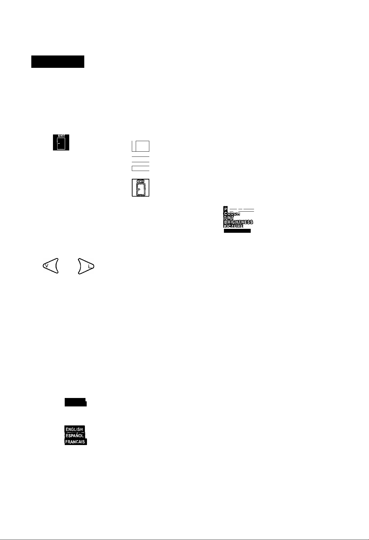
Menu Language Selection
The MENU LANGUAGE is factory set to ENGLISH.
Follow the instructions to change it to SPANISH,
FRENCH, and back to ENGLISH (TV, PC, and DTV
mode).
1 Press .
2. Press A or w and or to highlight
the Language ENGLISH /ESPANOUFRANQAIS
Icon.
3. Press to display the Language select menu.
iaaiLimw
SHARPEN ESS
I
__
am ^ gsfDiasmg
'W
4. Press A or w to highlight PICTURE NORM.
5. Press or to select “SET’ to normalize
Color, Tint, Brightness, Picture, and Sharpness.
6. Press twice to exit menus.
Color, Tint, Brightness, Picture, and
Sharpness Adjustments
tietpfui Hints:
COLOR - Adjust for desired color intensity.
TINT - Adjust for natural flesh tones.
BRIGHTNESS - Adjust so dark areas of picture
slightly became black for a crisp detail.
PICTURE - Adjust the white areas of the picture as
desired.
SHARPNESS - Adjust for best clarity of outline
detail.
ËSPANÛL
FRANÇAIS
Press A or to select ENGLISH, ESPAÑOL
or FRANÇAIS for the Language Menu.
Press ft^il twice to exit menus.
1. Press
2. Press A or w and or to highlight the
Picture Icon.
3. Press to display the Picture Adjustment
menu.
-16-
 Loading...