

Page 1

36sl13g.html
Table Of Contents
COVER
1 Safety precautions
2 Service notes
2.1 X-Ray Protection Circuit Check& Adjustments
3 EEPROM replacement
4 About lead free solder (PbF)
5 Receiver feature table
6 Board description table
7 TV Location of controls
8 Location of controls (EUR7613Z60 remote)
9 Location of controls (EUR7713010 remote)
10 Dissasembly for service
10.1 Disassembly for CRT replacement
11 Chassis service adjustment procedures
12 Purity and convergence procedure
12.1 DYNAMIC CONVERGENCE ADJUSTMENT
12.2 Permalloy convergence corrector strip (Part No. 0FMK014ZZ)
12.3 DAF adjustment(Dynamic focus adjustment)
13 Service mode (electronic adjustments)
13.1 Service adjustment default values for items
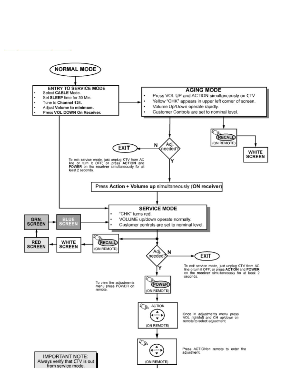
13.2 Instructional flow chart for service mode
13.3 Instructional flow chart for service mode (continued).
14 Service adjustments (electronic controls)
14.1 Sub-Brightness and ContrastService DAC adjustment (BRIGH, CONT)
14.2 Color output adjustmentService DAC adjustment (COLOR, TINT)
14.3 Color output adjustmentService DAC adjustment(COLOR, TINT, B-Y_G)
14.4 Color temperature adjustment(B/W Tracking)Service DAC Adjust.(CUT R) (CUT G) (CUT B) (R DR) (B DR)
14.5 Deflection adjustments
14.5.1 H-Center adjustment
14.5.2 H-Width adjustment
14.5.3 Trapezoid adjustment
14.5.4 Parallelogram adjustment
14.5.5 E-W PCC balance adjustment
14.5.6 Vertical linearity(V-C), V-Size and V-Position adjustment
14.5.7 V-S Correction adjustment
14.6 MTS circuit adjustments
14.7 Clock adjustment (CLOCK)
14.8 Service Adjustments Mechanical Controls
15 Identification of Components
15.1 A-Board components
15.1.1 D-Board components
15.1.2 G-Board components
15.1.3 L-Board components
16 Reference for PDF colors
17 Conductor views
17.1 A-Board printed circuit 1 of 2
17.2 A-Board printed circuit 2 of 2
17.3 D-Board printed circuit 1 of 2
17.4 D-Board printed circuit 2 of 2
17.5 G-Board (SC models) printed circuit 1 of 2
17.6 G-Board (SC models) printed circuit 2 of 2
17.7 G-Board (SL models) printed circuit 1 of 2
17.8 G-Board (SL models) printed circuit 2 of 2
17.9 L-Board printed circuit
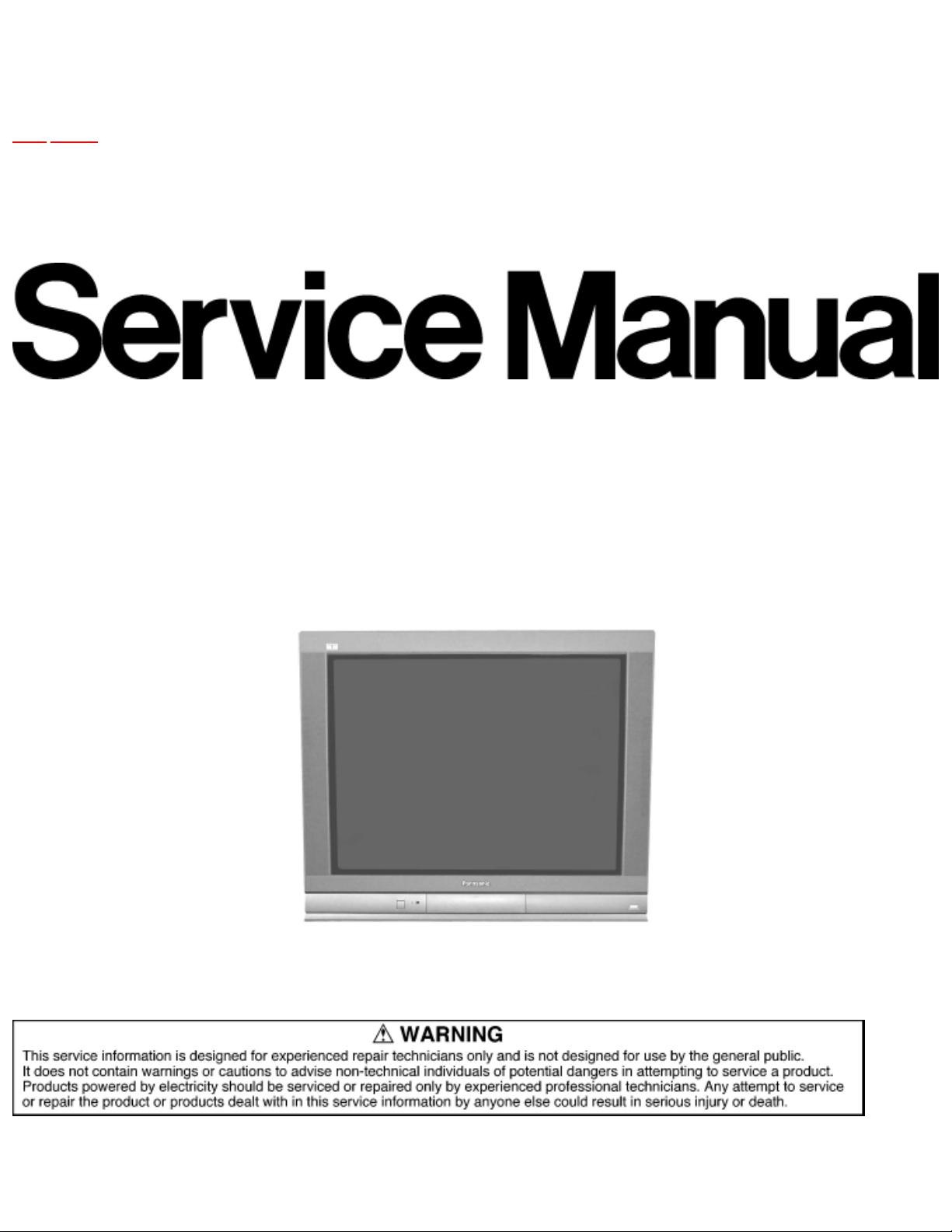
Service Manual
TOP NEXT
MTNC030729C1
B05
Color Television
● CT-36SL13G
CT-32SL13G
CT-36SC13G
CT-32SC13G
CT-3653G
NA10FL
Copyright 2003 Matsushita Electric Corporation of America. All rights reserved. Unauthorized copying and distribution is a
violation of law.
file:///C|/Documents and Settings/eDOK/Рабочий стол/NA10FL Ch_CT-36SL13G_32SL13G_36SC13G_32SC13G_3653G.htm (1 of 2)04.12.2008 23:59:58
Page 2

36sl13g.html
17.10 K-Board printed circuit
18 Block diagrams
18.1 Video signal block diagram
18.2 Audio signal block diagram
19 Schematics
19.1 English schematic notes
19.2 Notas de esquemáticos en español
19.3 A-Board schematic TNP2AH052NIL/AA (1 of 3)
19.4 A-Board schematic TNP2AH052NIL/AA (2 of 3)
19.5 A-Board schematic TNP2AH052NIL/AA (3 of 3)
19.6 D-Board schematic TNP2AH053NIL/AB (1 of 2)
19.7 D-Board schematic TNP2AH053NIL/AB (2 of 2)
19.8 G-Board (SC models) schematic TNP2AA141 (1 of 2)
19.9 G-Board (SC models) schematic TNP2AA141 (2 of 2)
19.10 G-Board (SL models) schematic TNP2AA142AB (1 of 2)
19.11 G-Board (SL models) schematic TNP2AA142AB (2 of 2)
19.12 L-Board schematic TNPA1673AE (1 of 2)
19.13 L-Board schematic TNPA1673AE (2 of 2)
19.14 K-Board schematic TNP2AA143
19.15 Voltages
19.16 Waveforms
20 Parts Location
21 Parts List
21.1 Parts List Notes
21.2 Parts List
TOP NEXT
file:///C|/Documents and Settings/eDOK/Рабочий стол/NA10FL Ch_CT-36SL13G_32SL13G_36SC13G_32SC13G_3653G.htm (2 of 2)04.12.2008 23:59:58
Page 3
http://tsn.pstc.panasonic.com/viewing/NA/CT-36SL13G/SVC/s0000000000.html
Service Manual
TOP NEXT
MTNC030729C1
B05
Color Television
● CT-36SL13G
CT-32SL13G
CT-36SC13G
CT-32SC13G
CT-3653G
NA10FL
http://tsn.pstc.panasonic.com/viewing/NA/CT-36SL13G/SVC/s0000000000.html (1 of 2)05.12.2008 0:00:05
Page 4

TOP NEXT
http://tsn.pstc.panasonic.com/viewing/NA/CT-36SL13G/SVC/s0000000000.html (2 of 2)05.12.2008 0:00:05
Page 5

http://tsn.pstc.panasonic.com/viewing/NA/CT-36SL13G/SVC/s0100000000x.html
1 Safety precautions
TOP PREVIOUS NEXT
General guidelines
An isolation transformer should always be used during the servicing of a receiver whose chassis is not
isolated from AC power line. Use a transformer of adequate power rating as this protects the technician
from accidents resulting in personal injuryfrom electrical shocks. It will also protect the receiver from
being damaged by accidental shorting that may occur during servicing.
When servicing, observe the original lead dress, especially in the high voltage circuit. Replace all
damaged parts (also parts that show signs of overheating.)
Always replace protective devices, such as fish paper, isolation resistors and capacitors, and shields after
servicing the receiver. Use only manufacturer’s recommended rating for fuses, circuits breakers, etc.
High potentials are present when this receiver is operating. Operation of the receiver without the rear
cover introduces danger for electrical shock. Servicing should not be performed by anyone who is not
thoroughly familiar with the necessary precautionswhen servicing high voltage equipment.
Extreme care should be practiced when handling the picture tube. Rough handling may cause it to
implode due to atmospheric pressure. (14.7 lbs per sq. in.). Do not nick or scratch the glass or subject it
to any undue pressure. When handling, usesafety goggles and heavy gloves for protection. Discharge the
picture tube by shorting the anode to chassis ground (not to the cabinet or to other mounting hardware).
When discharging connect cold ground (i.e. dag ground lead) to the anode with a wellinsulated wire or
use a grounding probe.Avoid prolonged exposure at close range to unshielded areas of the picture tube
to prevent exposure to x ray radiation.
The test picture tube used for servicing the chassis at the bench should incorporate safety glass and
magnetic shielding. The safety glass provide shielding for the tube viewing area against x ray radiation
as well as implosion. The magnetic shieldlimits the x ray radiation around the bell of the picture tube in
addition to the restricting magnetic effects. When using a picture tube test jig for service, ensure that the
jig is capable of handling 50kV without causing x ray radiation.
Before returning a serviced receiver to the owner, the service technician must thoroughly test the unit to
ensure that is completely safe to operate. Do not use a line isolation transformer when testing.
Leakage current cold check
http://tsn.pstc.panasonic.com/viewing/NA/CT-36SL13G/SVC/s0100000000x.html (1 of 3)05.12.2008 0:00:16
Page 6
http://tsn.pstc.panasonic.com/viewing/NA/CT-36SL13G/SVC/s0100000000x.html
Unplug the A.C. cord and connect a jumper between the two plug prongs.Measure the resistance
between the jumpered AC plug and expose metallic parts such as screwheads, antenna terminals, control
shafts, etc. If the exposed metallic part has a returnpath to the chassis, the reading should be between
240kΩ and 5.2MΩ. If the exposed metallic part does not have a return path to the chassis, the reading
should be infinite.
Leakage current hot check
Plug the AC cord directly into the AC outlet. Do not use an isolation transformer during the check.
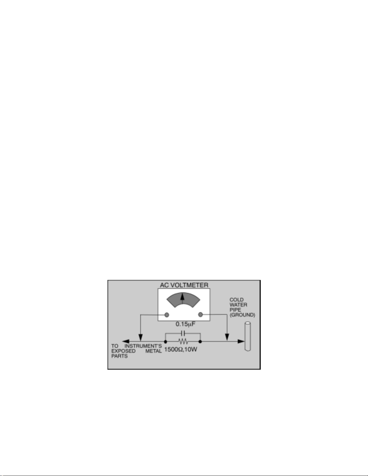
Connect a 1.5kΩ 10 watt resistor in parallel with a 0.15μF capacitor between an exposed metallic part
and ground. Use earth ground, for example a water pipe.
Using a DVM with a 1000 ohms/volt sensitivity or higher, measure the AC potential across the resistor.
Repeat the procedure and measure the voltage present with all other exposed metallic parts.
Verify that any potential does not exceed 0.75 volt RMS. A leakage current tester (such a Simpson
model 229, Sencore model PR57 or equivalent) may be used in the above procedure, in which case any
current measure must not exceed 0.5 milliamp. Ifany measurement is out of the specified limits, there is
a possibility of a shock hazard and the receiver must be repaired and rechecked before it is returned to
the customer.
Hot check circuit
Insulation test
Connect an insulation tester between an exposed metallic part and A.C. line. Apply 1080VAC/60Hz for
1 second. Confirm that the current measurement is 0.5mA ~ 2.0mA. Repeat test with other metallic
exposed parts.
X ray radiation
http://tsn.pstc.panasonic.com/viewing/NA/CT-36SL13G/SVC/s0100000000x.html (2 of 3)05.12.2008 0:00:16
Page 7

http://tsn.pstc.panasonic.com/viewing/NA/CT-36SL13G/SVC/s0100000000x.html
WARNING
The potential source of x ray radiation in the TV set is in the high voltage section and the picture tube.
NOTE
It is important to use an accurate, calibrated high voltage meter.
Set the brightness, picture, sharpness and color controls to minimum.
Measure the high voltage. The high voltage should be 33.0 ± 1.0kV. If the upper limit is out of
tolerance, immediate service and correction is required to insure safe operation and to prevent the
possibility of prematurecomponent failure.
Horizontal oscillator disable circuit test
This test must be performed as a final check before the receiver is returned to the customer. See
horizontal oscillator disable circuit procedure check in this manual.
TOP PREVIOUS NEXT
http://tsn.pstc.panasonic.com/viewing/NA/CT-36SL13G/SVC/s0100000000x.html (3 of 3)05.12.2008 0:00:16
Page 8

http://tsn.pstc.panasonic.com/viewing/NA/CT-36SL13G/SVC/s0200000000x.html
2 Service notes
TOP PREVIOUS NEXT
NOTE
These components are affixed with glue. Be careful not to break or damage any foil under the
component or at the pins of the ICs when removing. Usually applying heat to the component for a short
time while twisting with tweezers will break the componentloose.
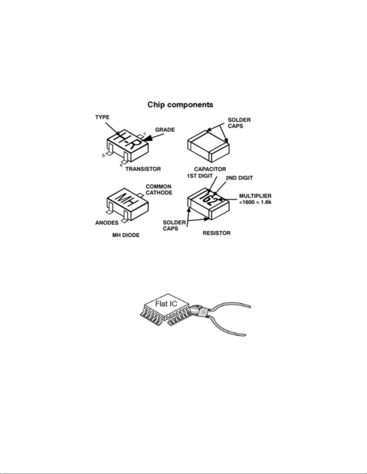
Leadless chip component (surface mount)
Chip components must be replaced with identical chips due to critical foil track spacing. There are no
holes in the board to mount standard transistors or diodes. Some chips capacitor or resistor board solder
pads may have holes through the board,however the hole diameter limits standard resistor replacement
to 1/8 watt. Standard capacitor may also be limited for the same reason. It is recommended that identical
components be used.
Chip resistor have a three digit numerical resistance code, 1st and 2nd significant digits and a multiplier.
Example: 162 = 1600 or 1.6kΩ resistor, 0 = 0Ω (jumper).
Chip capacitors generally do not have the value indicated on the capacitor. The color of the component
indicates the general range of the capacitance.
Chip transistors are identified by a two letter code. The first letter indicates the type and the second
letter, the grade of transistor.
Chip diodes have a two letter identification code as per the code chart and are a dual diode pack with
either common anode or common cathode. Check the parts list for correct diode number.
Component removal
1. Use solder wick to remove solder from component end caps or terminal.
2. Without pulling up, carefully twist the component with tweezers to break the adhesive.
3. Do not reuse removed leadless or chip components since they are subject to stress fracture during
removal.
http://tsn.pstc.panasonic.com/viewing/NA/CT-36SL13G/SVC/s0200000000x.html (1 of 4)05.12.2008 0:00:25
Page 9
http://tsn.pstc.panasonic.com/viewing/NA/CT-36SL13G/SVC/s0200000000x.html
Chip component installation
1. Put a small amount of solder on the board soldering pads.
2. Hold the chip component against the soldering pads with tweezers or with a miniature alligator
clip and apply heat to the pad area with a 30 watt iron until solder flows. Do not apply heat for
more than 3 seconds.
How to replace flat ic (required tools)
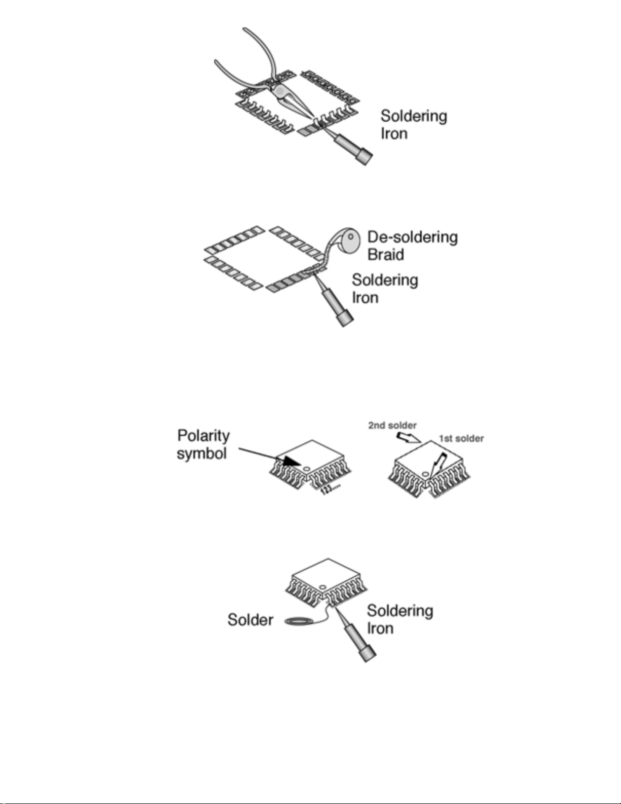
1. Remove the solder from all of the pins of a Flat IC by using a desolder braid
2. Put the iron wire under the pins of the Flat IC and pull it in the direction indicated while heating
the pins using a soldering iron. A small awl can be used instead of the iron wire.
http://tsn.pstc.panasonic.com/viewing/NA/CT-36SL13G/SVC/s0200000000x.html (2 of 4)05.12.2008 0:00:25
Page 10
http://tsn.pstc.panasonic.com/viewing/NA/CT-36SL13G/SVC/s0200000000x.html
3. Remove the solder from all the pads of the Flat IC by using a de solder braid
4. Position the new Flat IC in place (apply the pins of the Flat IC to the soldering pads where the
pins need to be soldered). Properly determine the positions of the soldering pads and pins by
correctly aligning the polarity symbol
5. Solder all pins to the soldering pads using a fine tipped soldering iron
6. Check with a magnifier for solder bridge between the pins or for dry joint between pins and
soldering pads. To remove a solder bridge, use a de solder braid as shown in the figure below
http://tsn.pstc.panasonic.com/viewing/NA/CT-36SL13G/SVC/s0200000000x.html (3 of 4)05.12.2008 0:00:25
Page 11

http://tsn.pstc.panasonic.com/viewing/NA/CT-36SL13G/SVC/s0200000000x.html
IMPORTANT
To protect against possible damage to the solid state devices due to arching or static discharge, make
certain that all ground wires and CRT DAG wire are securely connected.
CAUTION
The power supply circuit is above earth ground and the chassis cannot be polarized. Use an isolation
transformer when servicing the receiver to avoid damage to the test equipment or to the chassis. Connect
the test equipment to the proper ground(hot) or (cold) when servicing, or incorrect voltages will be
measured.
2.1 X-Ray Protection Circuit Check& Adjustments
TOP PREVIOUS NEXT
http://tsn.pstc.panasonic.com/viewing/NA/CT-36SL13G/SVC/s0200000000x.html (4 of 4)05.12.2008 0:00:25
Page 12
http://tsn.pstc.panasonic.com/viewing/NA/CT-36SL13G/SVC/s0201000000.html
2.1 X-Ray Protection Circuit Check& Adjustments
TOP PREVIOUS NEXT
This test must be performed as final check before the receiver is returned to the customer. If voltages are
out of tolerance, immediate service and correction is required to insure safe operation and to prevent the
possibility of premature componentfailure.
Equipment:
1. Isolation transformer.
2. High voltage meter.
3. D.C. Ammeter
4. Short jumper.
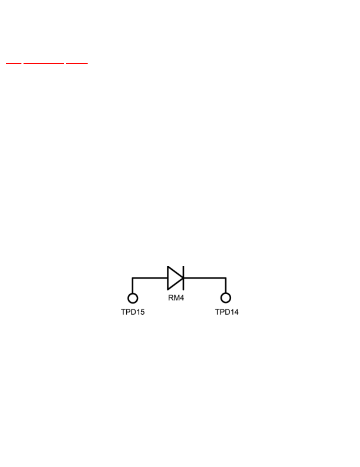
5. HHS jig (See figure below).
Diode Connection Jumper.
Preparation:
1. Make sure the receiver is turned off.
2. Connect the receiver to an isolation transformer.
3. Connect the ammeter serial from the flyback anode lead to the picture tube anode socket.
4. Prepare short jumper and HHS jig.
Procedure:
http://tsn.pstc.panasonic.com/viewing/NA/CT-36SL13G/SVC/s0201000000.html (1 of 2)05.12.2008 0:00:36
Page 13

http://tsn.pstc.panasonic.com/viewing/NA/CT-36SL13G/SVC/s0201000000.html
1. Connect the short jumper between TPD16 & TPD17.
2. Connect the jumper diode between TPD14 and TPD15 (anode connected to TPD15 and cathode
to TPD14).
3. Apply 75VAC to AC input of isolation transformer.
4. Turn the receiver on.
5. Apply a monoscope pattern.
6. Set customer picture and brightness controls to the minimum.
7. tSet current within 50μA to 100μA by changing the picture and bright controls.
8. Slowly increase AC voltage at the input of the isolation transformer and confirm HHS voltage
measure 36kV .
9. Turn power off and remove jigs.
TOP PREVIOUS NEXT
http://tsn.pstc.panasonic.com/viewing/NA/CT-36SL13G/SVC/s0201000000.html (2 of 2)05.12.2008 0:00:36
Page 14
http://tsn.pstc.panasonic.com/viewing/NA/CT-36SL13G/SVC/s0300000000x.html
3 EEPROM replacement
TOP PREVIOUS NEXT
If a new EEPROM integrated circuit is replaced for servicing, follow the next procedure once that the
memory is properly assembled:
1. Turn the TV set ON.
2. Enter to service mode.
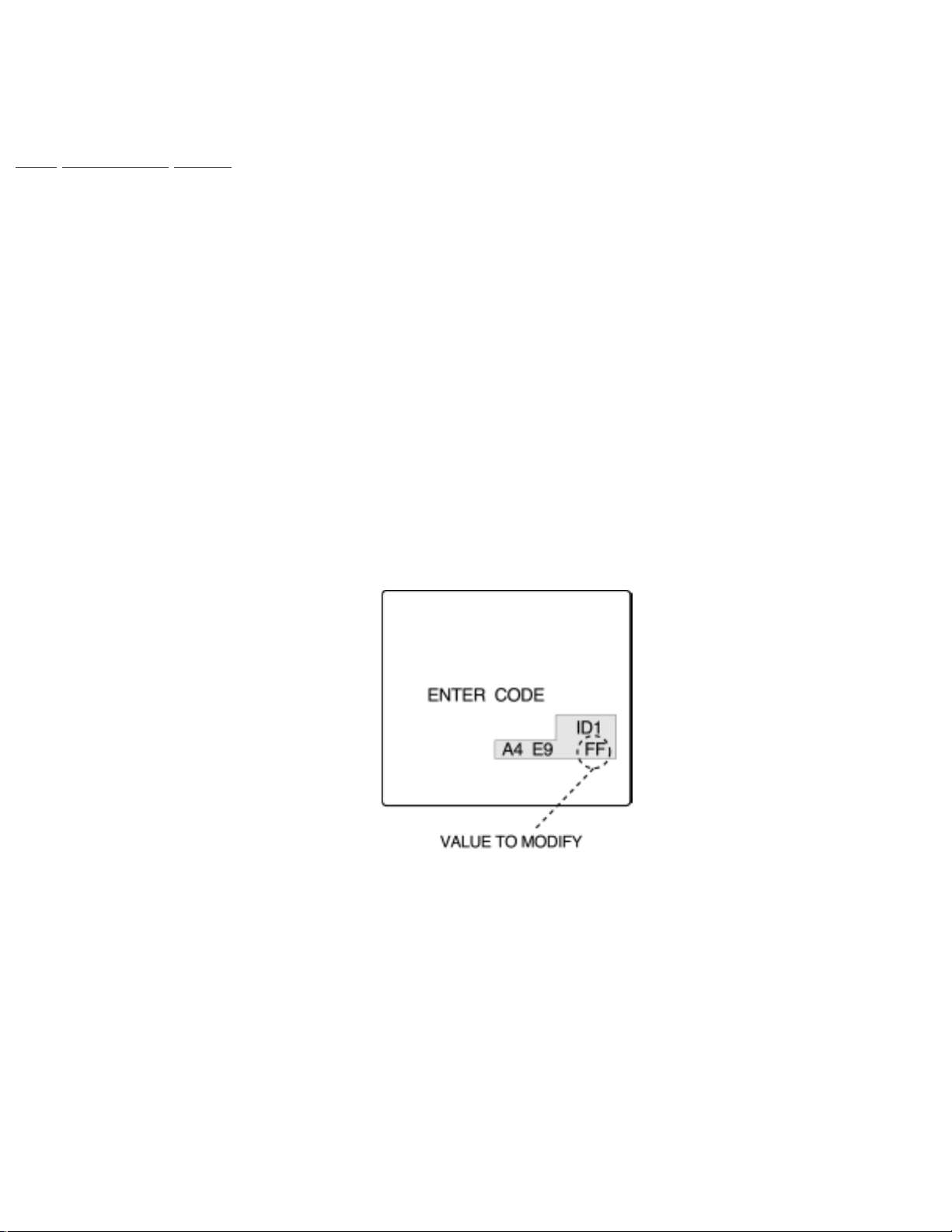
3. Once inside service mode the first image that appears on-screen is the ID1 register with the
respective address value (FF) like the image below.
Note:
All 3 registers (ID1,ID2,ID3) should appear with FF values if a new EEPROM is assembled.
4. With “VOL” keys adjust the correct value according with the service adjustment table (see
“Service Mode” section in page 15).
5. Change to the next ID switch register with “CH” keys and repeat the same procedure as step 4.
6. When replacing a new EEPROM be sure to set the correct ID switch values for each model.
7. Once that all 3 registers are set with the correct address value, perform all of the remaining
adjustments and servicing.
http://tsn.pstc.panasonic.com/viewing/NA/CT-36SL13G/SVC/s0300000000x.html (1 of 2)05.12.2008 0:00:41
Page 15

http://tsn.pstc.panasonic.com/viewing/NA/CT-36SL13G/SVC/s0300000000x.html
IMPORTANT:
Correct ID switch configuration should be input when replacing EEPROM for each television model,
otherwise if wrong values are configured, the television software will not function accordingly and
properly.
TOP PREVIOUS NEXT
http://tsn.pstc.panasonic.com/viewing/NA/CT-36SL13G/SVC/s0300000000x.html (2 of 2)05.12.2008 0:00:41
Page 16

http://tsn.pstc.panasonic.com/viewing/NA/CT-36SL13G/SVC/s0400000000x.html
4 About lead free solder (PbF)
TOP PREVIOUS NEXT
NOTE
Lead is listed as (Pb) in the periodic table of elements.
In the information below, Pb will refer to lead solder, and PbF will refer to Lead Free Solder.
The lead free solder used in our manufacturing process and discussed below is (Sn+Ag+Cu).
Thatis Tin (Sn), Silver (Ag) and Copper (Cu) although other types are available.
This model uses Pb Free solder in it’s manufacture due to environmental conservation issues. For
service and repair work, we’d suggest the use of Pb free solder as well, although Pb solder may be
used.
PCBs manufacturedusing lead free solder will have the “PbF” or a leaf symbol stamped on the
back of PCB.
CAUTION
● Pb free solder has a higher melting point than standard solder. Typically the melting point is 50 ~
70 °F (30 ~ 40 °C) higher. Please use a high temperature soldering iron and set it to 700 ± 20 °F
(370 ± 10 °C).
● Pb free solder will tend to splash when heated too high (about 1100 °F or 600 °C).
If you must use Pb solder, please completely remove all of the Pb free solder on the pins or solder
area before applying Pb solder. If thisis not practical, be sure to heat the Pb free solder until it
melts, before applying Pb solder.
● After applying PbF solder to double layered boards, please check the component side for excess
solder which may flow onto the opposite side.
http://tsn.pstc.panasonic.com/viewing/NA/CT-36SL13G/SVC/s0400000000x.html (1 of 2)05.12.2008 0:00:49
Page 17
http://tsn.pstc.panasonic.com/viewing/NA/CT-36SL13G/SVC/s0400000000x.html
Suggested Pb free solder
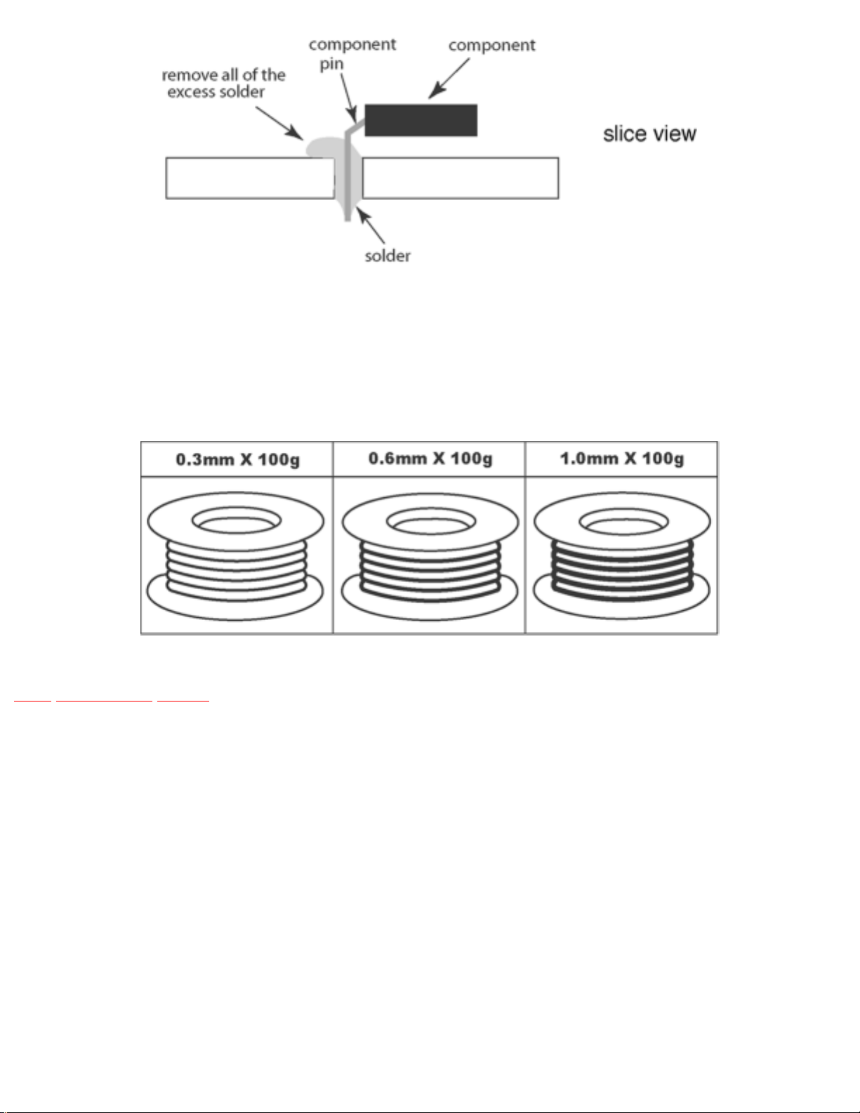
There are several kinds of Pb free solder available for purchase. This product uses Sn+Ag+Cu (tin,
silver, copper) solder. However, Sn+Cu (tin, copper), Sn+Zn+Bi (tin, zinc, bismuth) solder can also
beused.
TOP PREVIOUS NEXT
http://tsn.pstc.panasonic.com/viewing/NA/CT-36SL13G/SVC/s0400000000x.html (2 of 2)05.12.2008 0:00:49
Page 18

http://tsn.pstc.panasonic.com/viewing/NA/CT-36SL13G/SVC/s0500000000x.html
5 Receiver feature table
TOP PREVIOUS NEXT
FEATURE/MODEL CT-32SL13G CT-36SL13G
CHASSIS AP411 AP412
MICRO 128K
MENU LANGUAGE ENG/SPAN/FR
CLOSED CAPTION X
V-CHIP (USA/CANADA) X
CHANNEL COUNT 181
CHANNEL INFO BANNER X
VIDEO INPUT SKIP X
75 OHM INPUT X
REMOTE CONTROL EUR7613Z60
CRT SUPPLIER MDDA FLAT (4:3)
CHASSIS NA10FL
COMB FILTER MOTION ADP 3 DIG
HEC/VEC (X=BOTH) X
VM X (DIGITAL)
V/A NORM (X=BOTH) X
COLOR TEMP X
PRESET/INPUT LABELING X
VIDEO PICTURE MEMORY X
MTS/SAP/DBX X
BUILT-IN AUDIO POWER 10Wx2
No. OF SPEAKERS 2
BASS/BALANCE/TREBLE CONTROL X
AI SOUND X
SURROUND X
SPATIALIZER/BBE BBE
A/V IN (REAR/FRONT) 3(2/1)
A/V PROGRAM OUT X
http://tsn.pstc.panasonic.com/viewing/NA/CT-36SL13G/SVC/s0500000000x.html (1 of 4)05.12.2008 0:00:53
Page 19
http://tsn.pstc.panasonic.com/viewing/NA/CT-36SL13G/SVC/s0500000000x.html
AUDIO OUT (FAO:F, VAO:V) F, V
COMPONENT INPUT (Y, Pb, Pr) 1
S-VIDEO INPUT (REAR/FRONT) 1/1
EPJ/HPJ/MISC HPJ
FEATURE/MODEL CT-32SC13G CT-36SC13G
CHASSIS BP411 BP412
MICRO 128K
MENU LANGUAGE ENG/SPAN/FR
CLOSED CAPTION X
V-CHIP (USA/CANADA) X
CHANNEL COUNT 181
VIDEO INPUT SKIP X
75 OHM INPUT X
75 OHM INPUT X
REMOTE CONTROL EUR7613Z60
CRT SUPPLIER MDDA FLAT (4:3)
CHASSIS NA10FL
COMB FILTER 3-LINE
HEC/VEC (X=BOTH) X
VM X (DIGITAL)
V/A NORM (X=BOTH) X
COLOR TEMP X
PRESET/INPUT LABELING X
VIDEO PICTURE MEMORY X
MTS/SAP/DBX X
BUILT-IN AUDIO POWER 5Wx2
No. OF SPEAKERS 2 (DOME)
BASS/BALANCE/TREBLE CONTROL X
AI SOUND X
SURROUND X
SPATIALIZER/BBE BBE
A/V IN (REAR/FRONT) 3(2/1)
A/V PROGRAM OUT X
http://tsn.pstc.panasonic.com/viewing/NA/CT-36SL13G/SVC/s0500000000x.html (2 of 4)05.12.2008 0:00:53
Page 20
http://tsn.pstc.panasonic.com/viewing/NA/CT-36SL13G/SVC/s0500000000x.html
AUDIO OUT (FAO:F, VAO:V) F, V
COMPONENT INPUT (Y, Pb, Pr) 1
S-VIDEO INPUT (REAR/FRONT) 1/1
EPJ/HPJ/MISC HPJ
FEATURE/MODEL CT-3653G
CHASSIS BP412
MICRO 128K
MENU LANGUAGE ENG/SPAN/FR
CLOSED CAPTION X
V-CHIP (USA/CANADA) X
CHANNEL COUNT 181
VIDEO INPUT SKIP X
75 OHM INPUT X
75 OHM INPUT X
REMOTE CONTROL EUR7613Z60
EXTRA REMOTE CONTROL EUR7713010
CRT SUPPLIER MDDA FLAT (4:3)
CHASSIS NA10FL
COMB FILTER 3-LINE
HEC/VEC (X=BOTH) X
VM X (DIGITAL)
V/A NORM (X=BOTH) X
COLOR TEMP X
PRESET/INPUT LABELING X
VIDEO PICTURE MEMORY X
MTS/SAP/DBX X
BUILT-IN AUDIO POWER 7.5Wx2
No. OF SPEAKERS 2 (DOME)
BASS/BALANCE/TREBLE CONTROL X
AI SOUND X
SURROUND X
SPATIALIZER/BBE BBE
A/V IN (REAR/FRONT) 3(2/1)
http://tsn.pstc.panasonic.com/viewing/NA/CT-36SL13G/SVC/s0500000000x.html (3 of 4)05.12.2008 0:00:53
Page 21

http://tsn.pstc.panasonic.com/viewing/NA/CT-36SL13G/SVC/s0500000000x.html
A/V PROGRAM OUT X
AUDIO OUT (FAO:F, VAO:V) F, V
COMPONENT INPUT (Y, Pb, Pr) 1
S-VIDEO INPUT (REAR/FRONT) 1/1
EPJ/HPJ/MISC HPJ
Note:
Specifications are subject to change without notice or obligation.
NOTE:
CT-3653G includes EUR7613Z60 remote control and an extra remote control with part number
EUR7713010
TOP PREVIOUS NEXT
http://tsn.pstc.panasonic.com/viewing/NA/CT-36SL13G/SVC/s0500000000x.html (4 of 4)05.12.2008 0:00:53
Page 22
http://tsn.pstc.panasonic.com/viewing/NA/CT-36SL13G/SVC/s0600000000x.html
6 Board description table
TOP PREVIOUS NEXT
CT-32SL13G
BOARD PART NUMBER DESCRIPTION
A TNP2AH052AA MAIN BOARD
D TNP2AH053AB POWER SUPPLY
G TNP2AA142AB FRONT A/V BOARD
K TNP2AA143 KEY BOARD
L TNPA1673AE CRT BOARD
CT-36SL13G
BOARD PART NUMBER DESCRIPTION
A TNP2AH052 MAIN BOARD
D TNP2AH053 POWER SUPPLY
G TNP2AA142AB FRONT A/V BOARD
K TNP2AA143 KEY BOARD
L TNPA1673AE CRT BOARD
CT-32SC13G
BOARD PART NUMBER DESCRIPTION
A TNP2AH052AA MAIN BOARD
D TNP2AH053AB POWER SUPPLY
G TNP2AA141 FRONT A/V BOARD
L TNPA1673AE CRT BOARD
CT-36SC13G and CT-3653G
BOARD PART NUMBER DESCRIPTION
A TNP2AH052 MAIN BOARD
D TNP2AH053 POWER SUPPLY
G TNP2AA141 FRONT A/V BOARD
L TNP1673AE CRT BOARD
http://tsn.pstc.panasonic.com/viewing/NA/CT-36SL13G/SVC/s0600000000x.html (1 of 2)05.12.2008 0:01:03
Page 23

http://tsn.pstc.panasonic.com/viewing/NA/CT-36SL13G/SVC/s0600000000x.html
NOTE
When ordering a replacement board assembly, append an “S” to the board number
EXAMPLE
To order the A Board, the replacement board is TNP2AH052AAS.
TOP PREVIOUS NEXT
http://tsn.pstc.panasonic.com/viewing/NA/CT-36SL13G/SVC/s0600000000x.html (2 of 2)05.12.2008 0:01:03
Page 24

http://tsn.pstc.panasonic.com/viewing/NA/CT-36SL13G/SVC/s0700000000x.html
7 TV Location of controls
TOP PREVIOUS NEXT
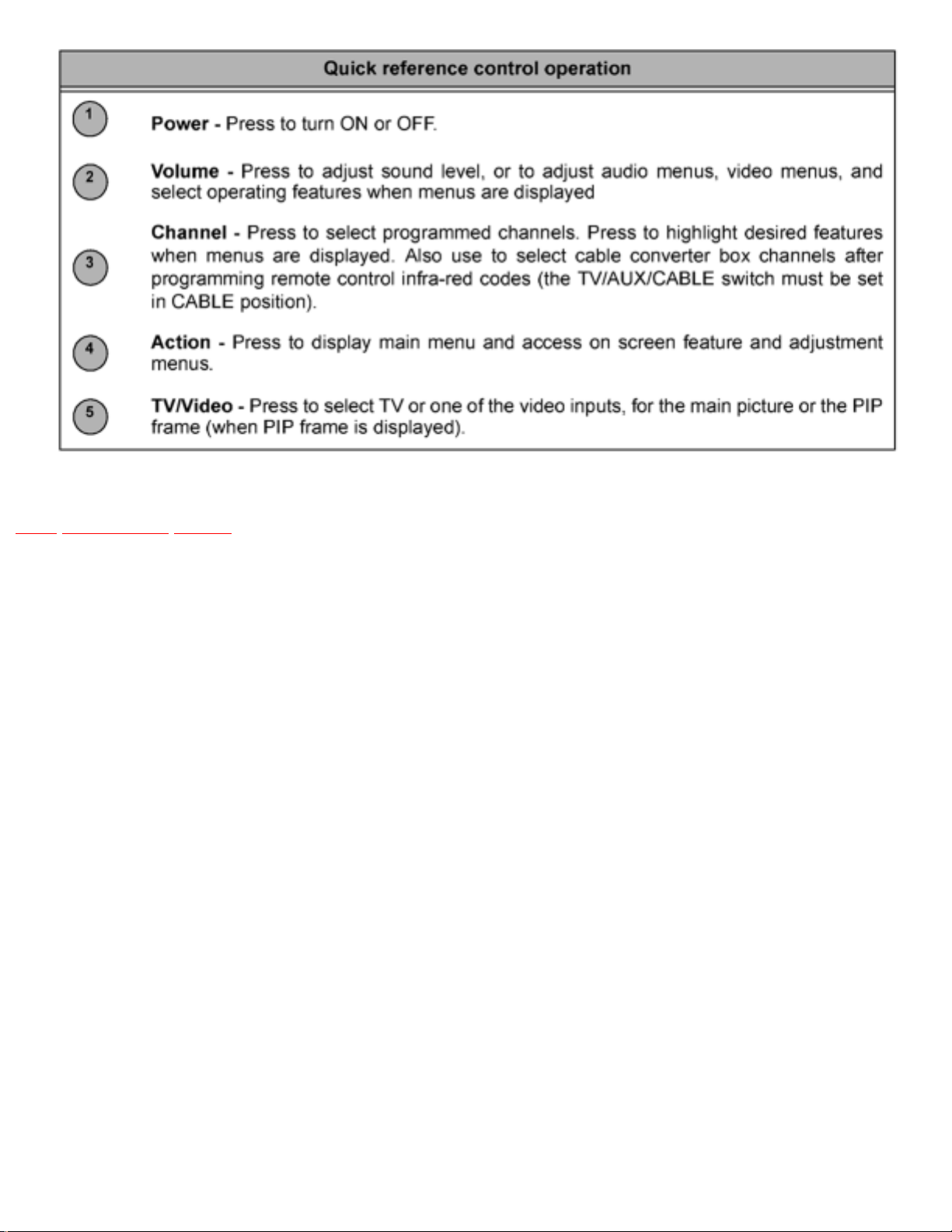
NOTE:
Front cabinet may vary depending on the model
User controls are inside the front door
http://tsn.pstc.panasonic.com/viewing/NA/CT-36SL13G/SVC/s0700000000x.html (1 of 2)05.12.2008 0:01:10
Page 25
http://tsn.pstc.panasonic.com/viewing/NA/CT-36SL13G/SVC/s0700000000x.html
TOP PREVIOUS NEXT
http://tsn.pstc.panasonic.com/viewing/NA/CT-36SL13G/SVC/s0700000000x.html (2 of 2)05.12.2008 0:01:10
Page 26
http://tsn.pstc.panasonic.com/viewing/NA/CT-36SL13G/SVC/s0800000000x.html
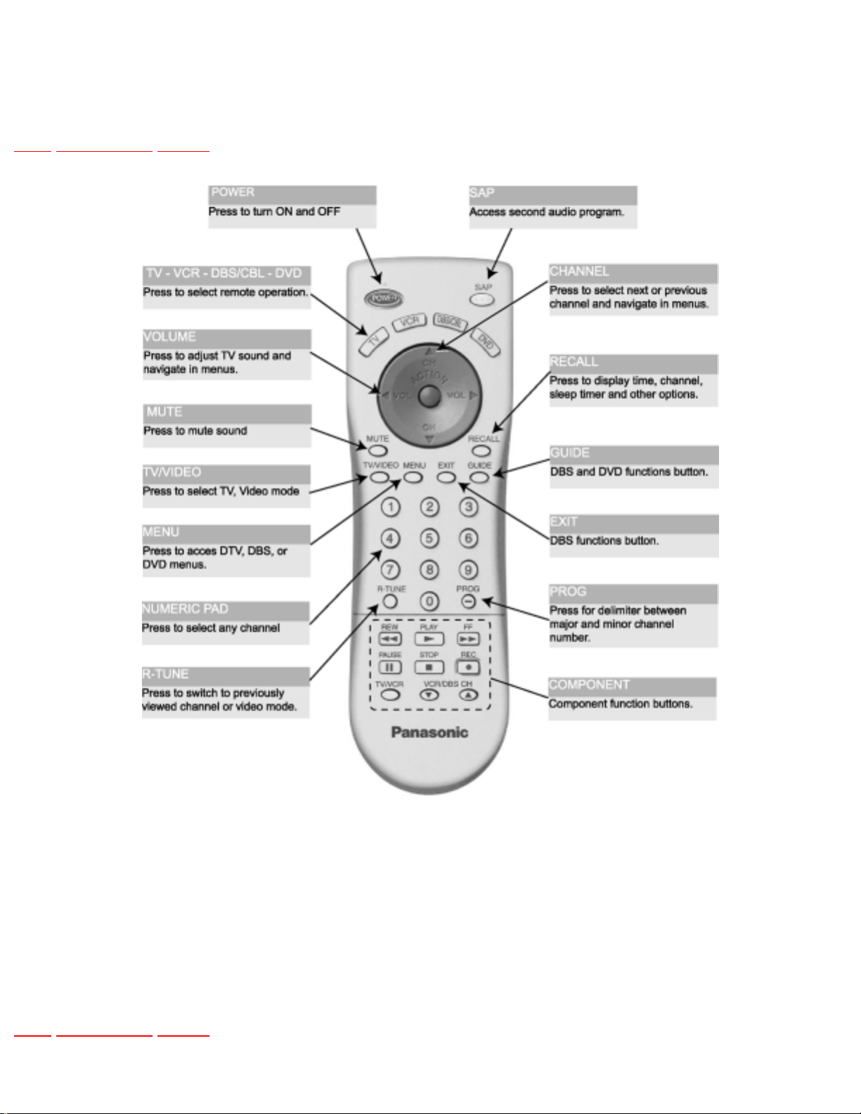
8 Location of controls (EUR7613Z60 remote)
TOP PREVIOUS NEXT
Note:
For additional information about this remote please refer to the owner’s manual section remote
operation, listed on the parts list section.
TOP PREVIOUS NEXT
http://tsn.pstc.panasonic.com/viewing/NA/CT-36SL13G/SVC/s0800000000x.html05.12.2008 0:01:19
Page 27
http://tsn.pstc.panasonic.com/viewing/NA/CT-36SL13G/SVC/s0900000000x.html
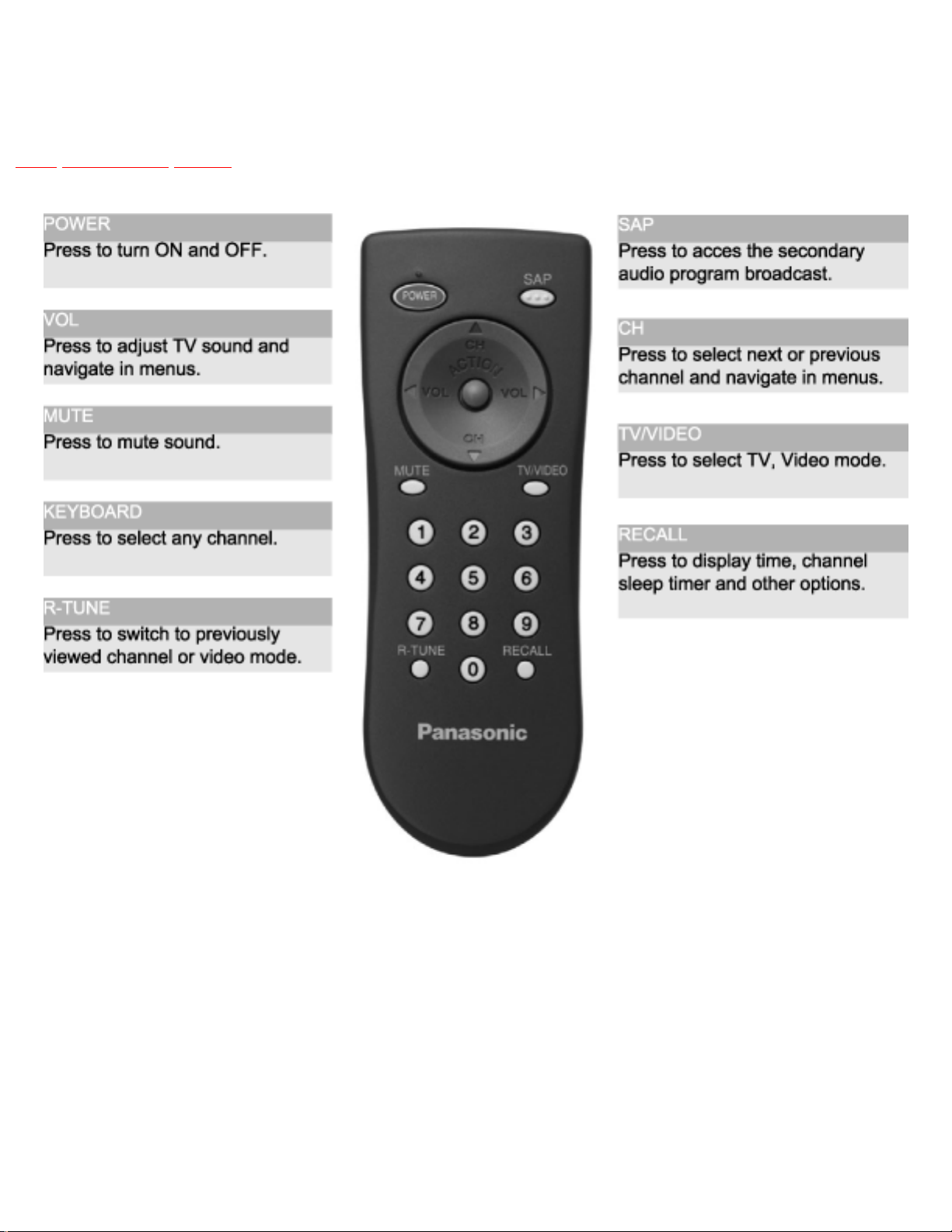
9 Location of controls (EUR7713010 remote)
TOP PREVIOUS NEXT
Note:
For additional information about this remote please refer to the owner’s manual section remote
operation, listed on the parts list section.
NOTE:
CT-3653G includes EUR7613Z60 remote control and an extra remote control with part number
EUR7713010
http://tsn.pstc.panasonic.com/viewing/NA/CT-36SL13G/SVC/s0900000000x.html (1 of 2)05.12.2008 0:01:24
Page 28

http://tsn.pstc.panasonic.com/viewing/NA/CT-36SL13G/SVC/s0900000000x.html
TOP PREVIOUS NEXT
http://tsn.pstc.panasonic.com/viewing/NA/CT-36SL13G/SVC/s0900000000x.html (2 of 2)05.12.2008 0:01:24
Page 29

http://tsn.pstc.panasonic.com/viewing/NA/CT-36SL13G/SVC/s1000000000x.html
10 Dissasembly for service
TOP PREVIOUS NEXT
Back cover
Remove all the screws marked with an arrow (←) from the back of the receiver
NOTE
Screw location and quantity may vary depending on the model of the receiver serviced and the
application; various models are covered in this manual. Use same hardware when reassembling the
receiver.
● 4 screws at the top edge of the receiver.
● 4 screw by the A/V jacks.
● 1 screw by the antenna jacks.
● 1 screw at the lower part of TV.
● 1 screw at each lower corner of the receiver.
● 1 screw by the retainer plate of the AC power cord.
● 1 screw by the A.C. cord assembly.
NOTE
Extensions for board connectors may be needed to take voltages on some boards, please see parts list
section for part numbers in this service manual.
A-Board - Main chassis
The A-Board assembly rest on a chassis tray along with the D-Board.
Slide chassis tray out. Gently lift the tray and pull out. Disconnect plug connectors; release wire ties and
holders as required for complete chassis removal.
http://tsn.pstc.panasonic.com/viewing/NA/CT-36SL13G/SVC/s1000000000x.html (1 of 4)05.12.2008 0:01:30
Page 30

http://tsn.pstc.panasonic.com/viewing/NA/CT-36SL13G/SVC/s1000000000x.html
1. A-Board is secured to the chassis tray with screws.
2. The A-Board is mated to the D-Board by three flexible connectors: A5, A6 & A7 (D5, D6 & D7
on the D-Board, respectively). To remove either boards, unplug the connectors on the A-Board.
NOTE
Some tie-wraps that secure the wire dressings may need to be unfastened for chassis removal
D-Board - Deflection
The D-Board assembly rest on a chassis tray along with the A-Board.
Slide chassis tray out. Gently lift the tray and pull out. Disconnect plug connectors; release wire ties and
holders as required for complete chassis removal.
1. D-Board is secured to the chassis tray with screws.
2. The D-Board is mated to the A-Board by three flexible connectors: D5, D6 and D7 (A5, A6 &
A7 on the A-Board, respectively). To remove either boards, unplug the connectors on the ABoard.
NOTE
Some tie-wraps that secure the wire dressings may need to be unfastened for chassis removal
L-Board - CRT output
Plugs into the socket on the CRT neck.
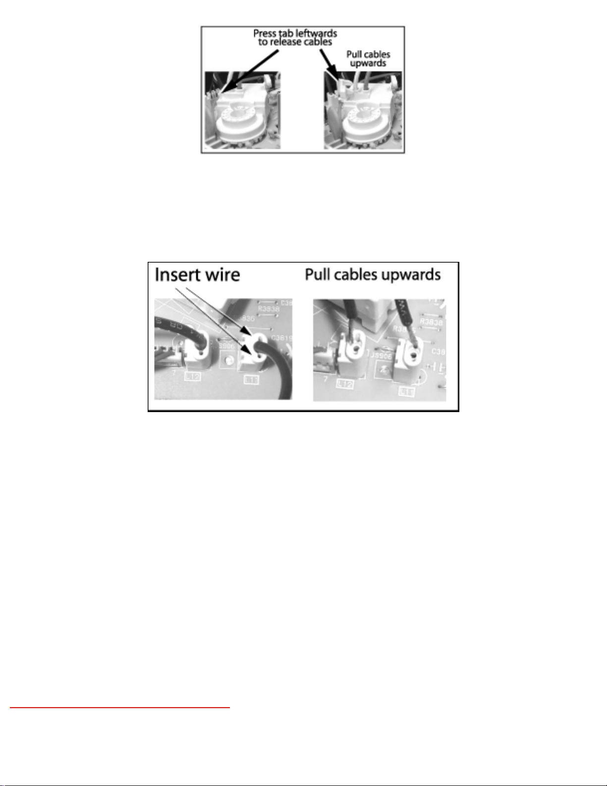
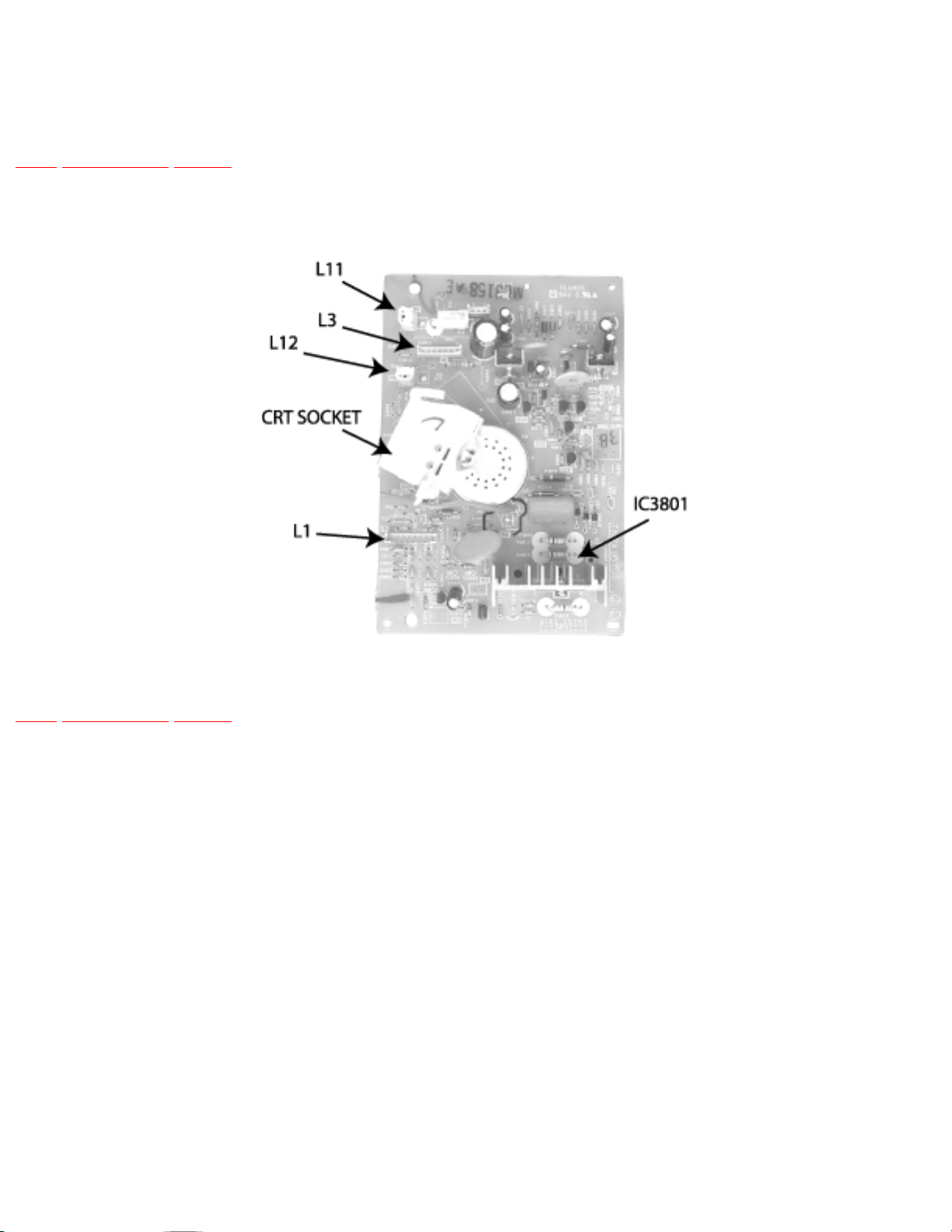
To remove this board, first unplug the board from the CRT neck, then disconnect L1, L2 and L3
connectors, to disconnect the focus F1(red cable) & F2 (white cable) cables from the CRT socker, pull
the tab and release the cables (see figure),finally disconnect the screen cable from the D-Board D16
(screen and heater).
To reinsert back the cables, remember the original position of cables, F1 (red cable) goes to A on the
CRT socket and F2 (white cable) goes to B on the CRT socket.
F1 and F2 cables release
http://tsn.pstc.panasonic.com/viewing/NA/CT-36SL13G/SVC/s1000000000x.html (2 of 4)05.12.2008 0:01:30
Page 31
http://tsn.pstc.panasonic.com/viewing/NA/CT-36SL13G/SVC/s1000000000x.html
To release screen GND cables from L-Board L11 & L12 connectors, insert a wire in both sides of
connector and pull upwards the cable, then remove the wire.
L11 and L12 cables release
G-Board
Mated to A-Board by three flexible connectors A1, A2, A3 and D40 from D-Board. To remove this
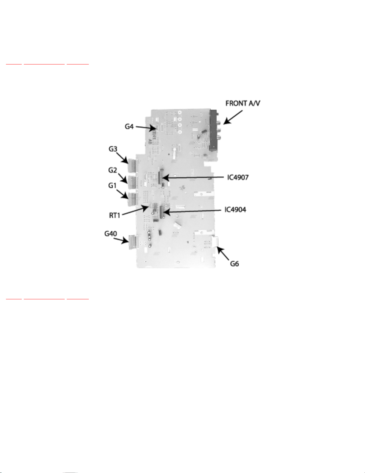
board, first unplug the four flexible connectors, then RT1 and G4connectors, then pull upwards the
board while unlock the tabs from the chassis tray.
Speakers
Each speaker is secured to a plastic base with 4 screws, and each plastic base is secured to the from
cabinet with two screws.
NOTE
When reassembling speakers be sure to connect the speaker wires to the correct speaker lead (+) (-)
10.1 Disassembly for CRT replacement
http://tsn.pstc.panasonic.com/viewing/NA/CT-36SL13G/SVC/s1000000000x.html (3 of 4)05.12.2008 0:01:30
Page 32

http://tsn.pstc.panasonic.com/viewing/NA/CT-36SL13G/SVC/s1000000000x.html
TOP PREVIOUS NEXT
http://tsn.pstc.panasonic.com/viewing/NA/CT-36SL13G/SVC/s1000000000x.html (4 of 4)05.12.2008 0:01:30
Page 33

http://tsn.pstc.panasonic.com/viewing/NA/CT-36SL13G/SVC/s1001000000.html
10.1 Disassembly for CRT replacement
TOP PREVIOUS NEXT
1. Discharge the CRT as instructed in the “safety precautions” section and remove 2nd anode button
from the CRT.
2. Remove speaker modules (R and L)
3. Perform complete removal of chassis, as instructed in “disassembly for service” section.
NOTE
When remounting the CRT, reuse the metal sheet located in the lower part of the cabinet holding
the CRT, hold with screws to the cabinet. This metal sheet is not supplied with the CRT
replacement.
CRT replacement
1. Perform “disassembly for CRT replacement” procedure.
2. Insure that the CRT H.V. Anode button is discharged before handling the CRT. Read the “safety
precautions” section on handling the picture tube.
3. Remove the components from the CRT neck and place the cabinet face down on a soft pad.
4. Note the original order for the CRT mounting hardware as they are remove from the CRT
mounting brackets at each corner of the CRT.
5. Remove the CRT with the degaussing coil and the dag ground braid attached.
NOTE
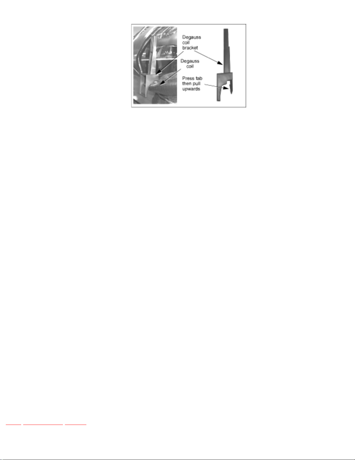
To remove the four brackets holding the degauss coil from the corners of the CRT, first remove
the CRT from the cabinet, then remove the brackets by pressing the tab on the bracket and pull
upwards. These brackets are included in the degauss coilkit, for part number, please see parts list
section
Brackets removal
http://tsn.pstc.panasonic.com/viewing/NA/CT-36SL13G/SVC/s1001000000.html (1 of 2)05.12.2008 0:01:40
Page 34
http://tsn.pstc.panasonic.com/viewing/NA/CT-36SL13G/SVC/s1001000000.html
6. Note the original locations and mounting of the degaussing coil and the dag ground assembly to
insure proper reinstallation on the replacement CRT.
To remove and remount the degaussing coil:
❍ Unhook the coil spring from the bottom corners of the CRT ears.
❍ Release the braid loop from the upper corners of the CRT ears.
7. Mount the dag ground braid on the replacement CRT. Position the degaussing coil with new ties.
Dress coil as was on the original CRT.
8. Replace the components on CRT neck and reinstall into cabinet. Verify that all ground wires and
circuit board plugs get connected.
NOTE
Reuse all the clampers and mounting brackets from the degauss coil and screen, and when
remounting the degauss coil assure that is not touching the speakers, this can be done by placing
some tape, this may cause mask vibration. The mounting brackets andclampers are not supplied
with the replacements.
IMPORTANT NOTICE
When ordering the CRT, please order CRT and CRT kit also. Please see parts list section for part
numbers.
TOP PREVIOUS NEXT
http://tsn.pstc.panasonic.com/viewing/NA/CT-36SL13G/SVC/s1001000000.html (2 of 2)05.12.2008 0:01:40
Page 35
http://tsn.pstc.panasonic.com/viewing/NA/CT-36SL13G/SVC/s1100000000x.html
11 Chassis service adjustment procedures
TOP PREVIOUS NEXT
All service adjustments are factory preset and should not require adjustment unless controls and/or
associated components are replaced.
Note:
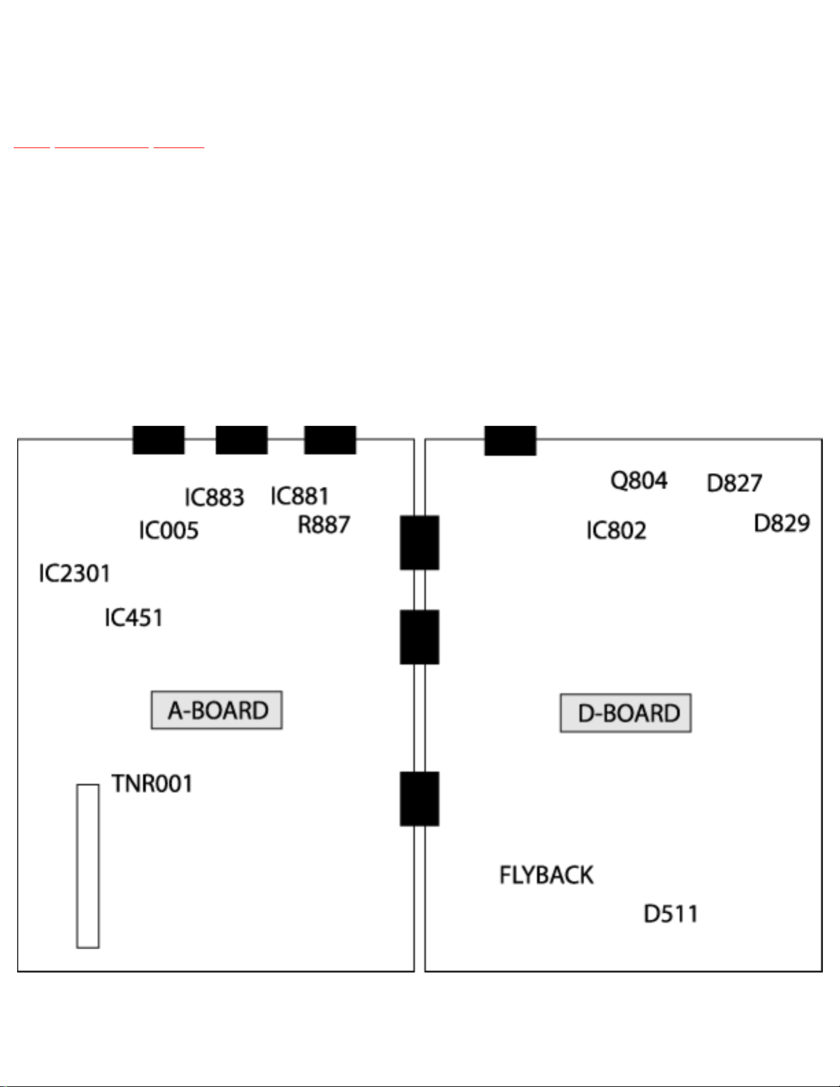
Connect the (-) lead of the voltmeter to the appropriate ground. Use IC801’s heat sink when the HOT
ground symbol is used. Otherwise, use COLD ground (tuner shield, IC451’s heat sink or FA2).
Component and Voltage Test Points
Note:
http://tsn.pstc.panasonic.com/viewing/NA/CT-36SL13G/SVC/s1100000000x.html (1 of 3)05.12.2008 0:01:45
Page 36
http://tsn.pstc.panasonic.com/viewing/NA/CT-36SL13G/SVC/s1100000000x.html
Components and test points within doted areas are located on trace side.
B+ voltage check
1. Set the BRIGHT and PICTURE to minimum by using the PICTURE menu.
2. Connect the DVM between TPD145 and cold ground.
3. Confirm that B+ voltage is 144.7 ± 1.5V. This voltage supplies B+ to the horizontal output and
flyback circuits.
Source voltage chart
120V AC line input. Set the BRIGHT and the PICTURE to minimum by using the PICTURE menu. Use
cold or hot ground for the (-) lead of the DVM as needed.
D-BOARD LOCATION TEST POINT VOLTAGE
+B2 by IC802 TPD145 144.7 ± 1.5V
9V by Q804 TPD9 8.2 ± 1.5V
15V by D827 TPD14 14.6 ± 2.0 V
15V (VER) by D827 TPD15 15.0 ± 1.5 V
+15V (VER) by D827 TPD17 -14.9 ± 1.5V
SOUND by D829 TPD30 31.8 ± 2.0V
220V by D511 TPD7 210.0 ± 9.0V
A-BOARD LOCATION TEST POINT VOLTAGE
MAIN 12V by IC883 TPA6 12.0 ± 0.5V
MAIN 9V by R887 TPA7 9.0 ± 0.5V
MAIN 5V by IC881 TPA8 5.0 ± 0.3V
STBY 3.3V by IC005 TPA16 3.3 ± 0.2V
BTL 30V by TNR002 TPA18 30.0 ± 2.0V
High voltage check
1. Select an active TV channel and confirm that horizontal is in sync.
2. Adjust BRIGHTNESS and CONTRAST using PICTURE icon menu so video just disappears.
http://tsn.pstc.panasonic.com/viewing/NA/CT-36SL13G/SVC/s1100000000x.html (2 of 3)05.12.2008 0:01:45
Page 37

http://tsn.pstc.panasonic.com/viewing/NA/CT-36SL13G/SVC/s1100000000x.html
3. Using a high voltage meter confirm that the high voltage is 33.0 ± 1.0kV.
TOP PREVIOUS NEXT
http://tsn.pstc.panasonic.com/viewing/NA/CT-36SL13G/SVC/s1100000000x.html (3 of 3)05.12.2008 0:01:45
Page 38
http://tsn.pstc.panasonic.com/viewing/NA/CT-36SL13G/SVC/s1200000000x.html
12 Purity and convergence procedure
TOP PREVIOUS NEXT
Adjustment is necessary only if the CRT or the deflection yoke is replaced or if the setting was
disturbed. The complete procedure consists of:
1. Vertical raster shift adjustment.
2. Initial static convergence.
3. Setting the purity.
4. Final static convergence.
WHEN THE CRT OR THE YOKE IS REPLACED
For 2 piece assembly:
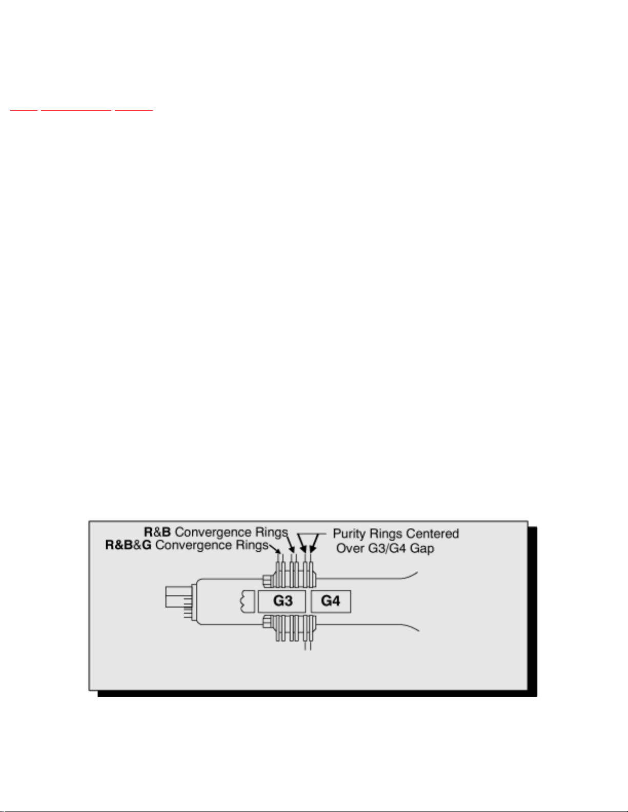
Position purity/convergence assembly as shown and tighten clamp snugly. Remove the hot-melt glue
seal on assembly and position like tabs of purity device together at 12 o’ clock to reduce its magnetic
field effect.
2 piece assembly
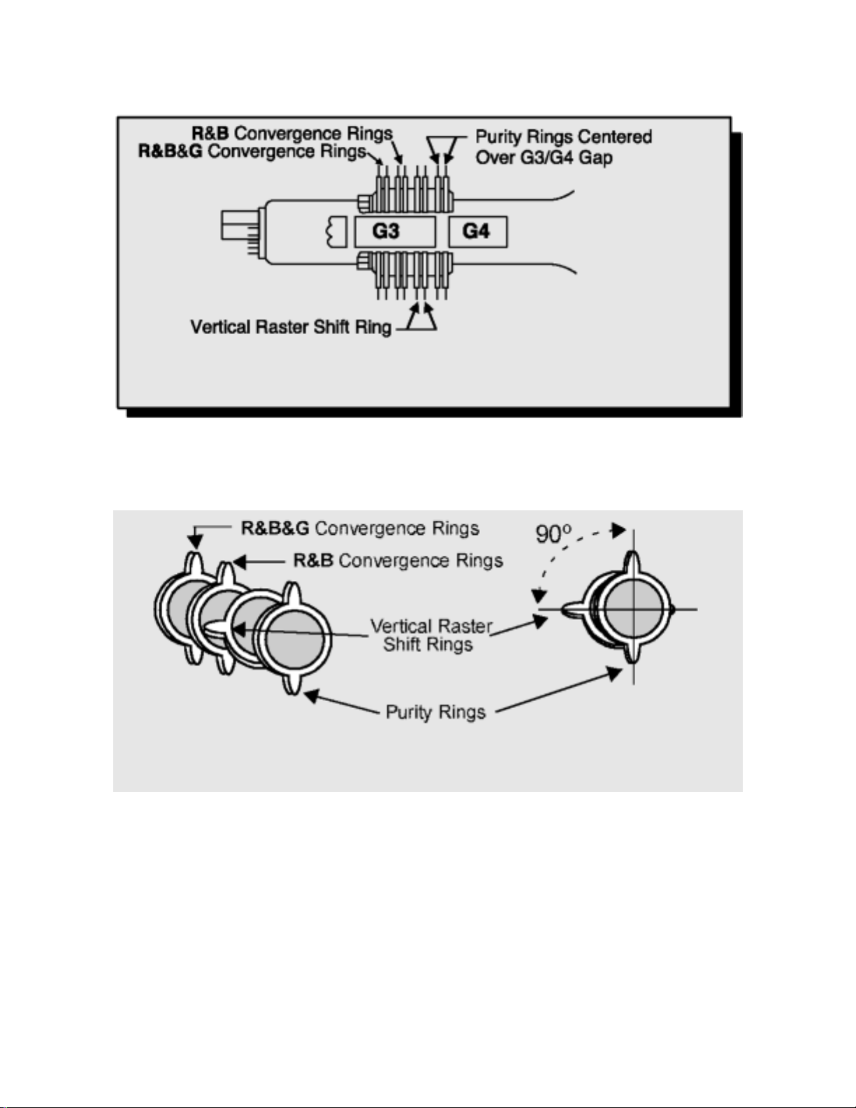
For models using 4 pairs of rings, place the yoke on the CRT neck (do not tighten the clamp). Place the
vertical raster shift tabs at 3 o’clock (90° from the purity and convergence tabs.
http://tsn.pstc.panasonic.com/viewing/NA/CT-36SL13G/SVC/s1200000000x.html (1 of 5)05.12.2008 0:01:52
Page 39
http://tsn.pstc.panasonic.com/viewing/NA/CT-36SL13G/SVC/s1200000000x.html
Description of rings
Initial position of rings
Turn the receiver ON. Operate the receiver for 60 minutes using the first purity check field (white
screen) to stabilize the CRT.
Fully degauss the receiver by using an external degaussing coil.
Slide the deflection yoke back and forth on the neck of the CRT until it produces a near white, uniform
raster.
VERTICAL RASTER SHIFT ADJUSTMENT
http://tsn.pstc.panasonic.com/viewing/NA/CT-36SL13G/SVC/s1200000000x.html (2 of 5)05.12.2008 0:01:52
Page 40
http://tsn.pstc.panasonic.com/viewing/NA/CT-36SL13G/SVC/s1200000000x.html
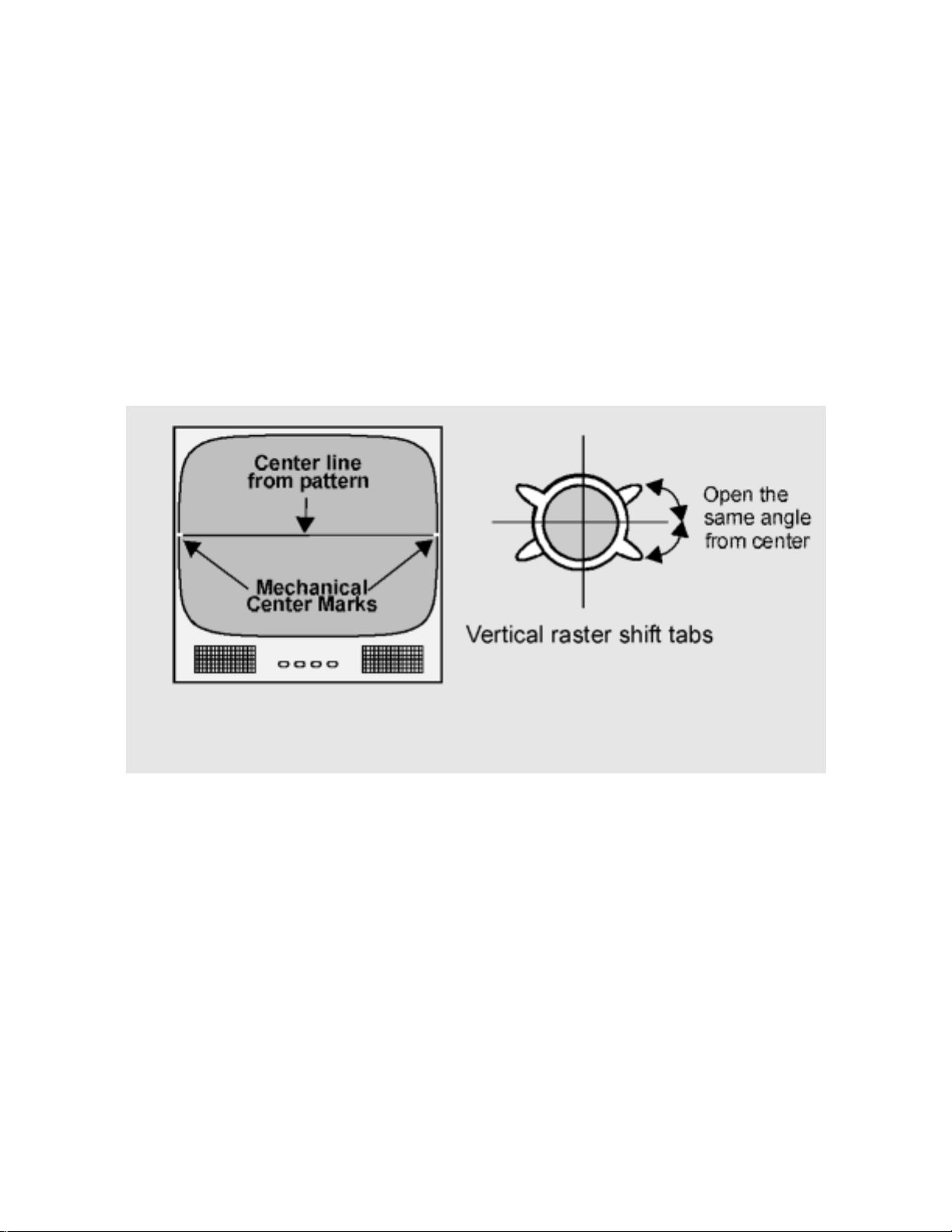
Apply a green pattern with a horizontal line, adjust the Deflection Yoke so that has no tilt, then secure it.
Adjust center line of the pattern with the mechanical center of the CRT, this center is determined by two
marks at the side edges of the screen. To adjust the line, once the vertical raster shift tabs are place at 3
o’clock to reduce itsmagnetic field effect open the tabs the same angle from the center, until the center
line of the pattern becomes a straight line, centered with the marks of the CRT.
IMPORTANT NOTICE
Rings come along with deflection yoke in one piece.
Vertical raster shift adjustment
INITIAL CENTER STATIC CONVERGENCE
Connect a dot/cross hatch generator to the receiver and tune in a signal. Observe misconvergence at
center of the screen only.
Adjust the R&B pole magnets; by separating tabs and rotating to converge blue with red.
Adjust the R&B and R&B&G pole magnets: by separating tabs and rotating to converge blue and red
(magenta) with green.
NOTE
Precise convergence at this point is not important.
http://tsn.pstc.panasonic.com/viewing/NA/CT-36SL13G/SVC/s1200000000x.html (3 of 5)05.12.2008 0:01:52
Page 41
http://tsn.pstc.panasonic.com/viewing/NA/CT-36SL13G/SVC/s1200000000x.html
PURITY ADJUSTMENT
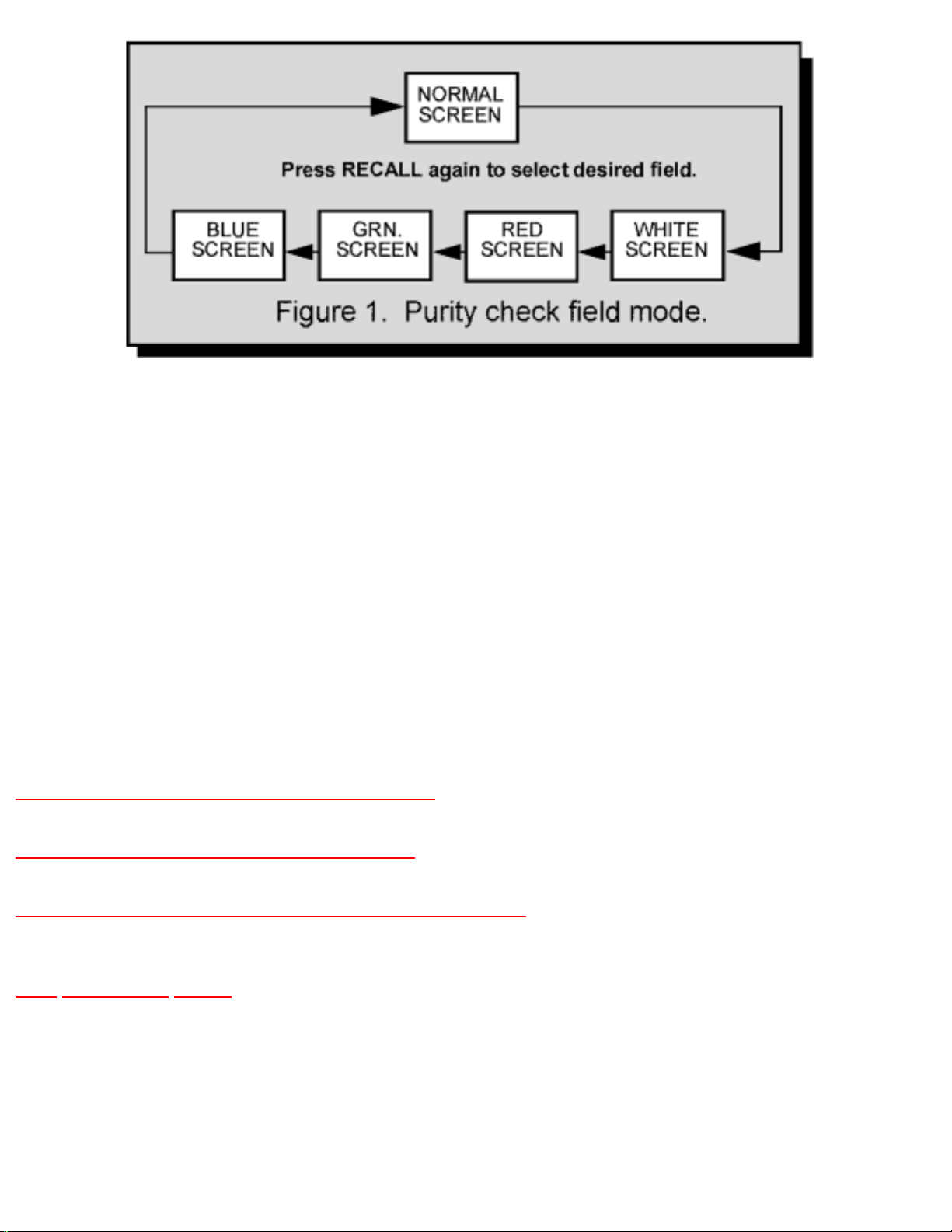
When the receiver is in the serviceman mode for making electronic adjustments, press the RECALL
button on the remote control to enter purity check. (See the service adjustments electronic controls
procedure).
Operate the receiver for 60 minutes using the first purity check field (white screen) to stabilize the CRT.
Fully degauss the receiver by using an external degaussing coil.
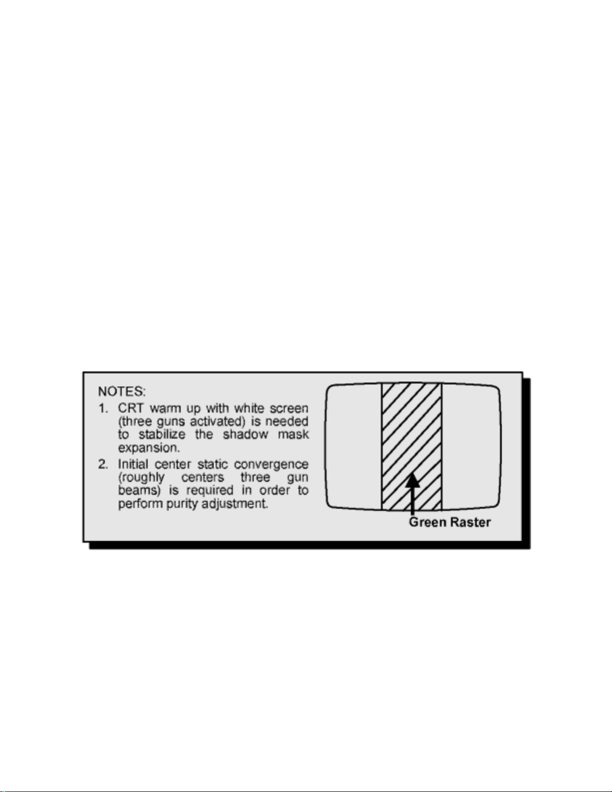
Press the RECALL button on the remote control again until the purity check (green screen) appears.
Loosen the deflection yoke clamp screw and move the deflection yoke back as close to the purity
magnet as possible.
Adjust the purity rings to set the vertical green raster precisely at the center of the screen.
Green raster adjustment
Slowly move the deflection yoke forward until the best overall green screen is displayed.
Tighten the deflection yoke clamp screw.
Press the RECALL button on the remote control again until the purity check blue and red screens appear
and observe that good purity is obtained on each respective field.
Press the RECALL button on the remote control again until purity check (white screen) appears.
Observe the screen for uniform white. If purity has not been achieved, repeat the above procedure.
http://tsn.pstc.panasonic.com/viewing/NA/CT-36SL13G/SVC/s1200000000x.html (4 of 5)05.12.2008 0:01:52
Page 42

http://tsn.pstc.panasonic.com/viewing/NA/CT-36SL13G/SVC/s1200000000x.html
FINAL CONVERGENCE PROCEDURE
NOTE
Vertical size and focus adjustments must be completed prior to performing the convergence adjustment.
Connect a dot pattern generator to the receiver. The brightness level should not be higher than necessary
to obtain a clear pattern.
Converge the red and the blue dots at the center of the screen by rotating the R&B pole static
convergence magnets.
Align the converged red/blue dots with the green dots at the center of the screen by rotating the R&B&G
pole static convergence magnets. Melt wax with soldering iron to reseal the magnets.
Slightly tilt vertically and horizontally (do not rotate) the deflection yoke to obtain a good overall
convergence.
If convergence is not reached at the edges, insert permalloy in the DY corners to achieve proper
convergence. Recheck for purity and readjust if necessary.
After vertical adjustment of the yoke, insert wedge at 11 o’clock position, then make the horizontal
tilt adjustment.
Secure the deflection yoke by inserting four side wedges.
Apply adhesive between tab (thin portion) of wedge and CRT and place tape over the tab to secure to the
CRT.
12.1 DYNAMIC CONVERGENCE ADJUSTMENT
12.2 Permalloy convergence corrector strip (Part No. 0FMK014ZZ)
12.3 DAF adjustment(Dynamic focus adjustment)
TOP PREVIOUS NEXT
http://tsn.pstc.panasonic.com/viewing/NA/CT-36SL13G/SVC/s1200000000x.html (5 of 5)05.12.2008 0:01:52
Page 43
http://tsn.pstc.panasonic.com/viewing/NA/CT-36SL13G/SVC/s1201000000.html
12.1 DYNAMIC CONVERGENCE ADJUSTMENT
TOP PREVIOUS NEXT
Use this for a precisely overall convergence adjust at the edges.
DY(YHC, YV, XV) ADJUSTMENT
YV ADJUSTMENT
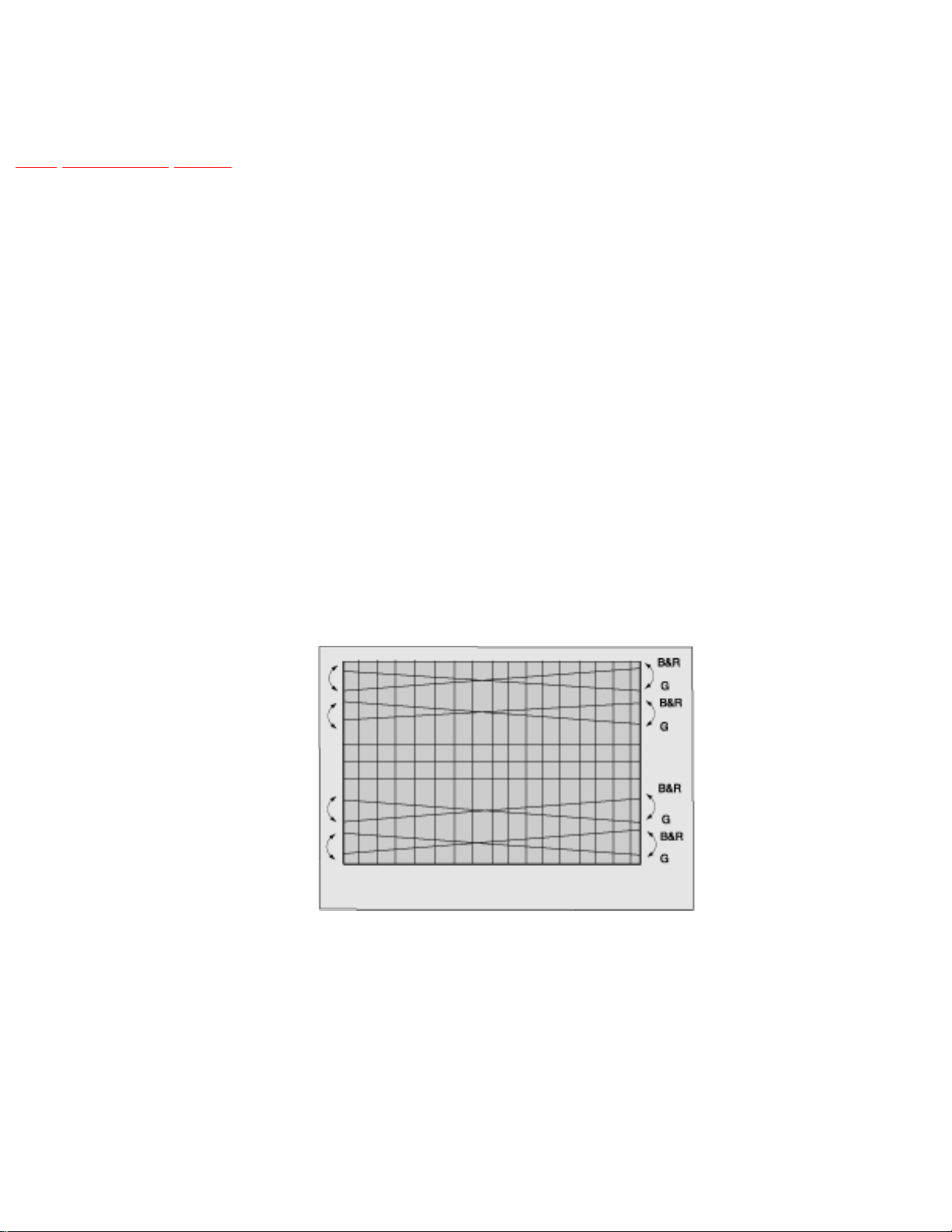
(VR1 FOR HORIZONTAL DYNAMIC CONVERGENCE)
1. Apply a crosshatch pattern.
2. Adjust contrast and brightness customer controls to obtain a correct picture.
3. With a driver adjust VR1 (located in deflection yoke board to obtain a proper corvergence at top
and bottom of the screen
VR1 adjustment (YV)
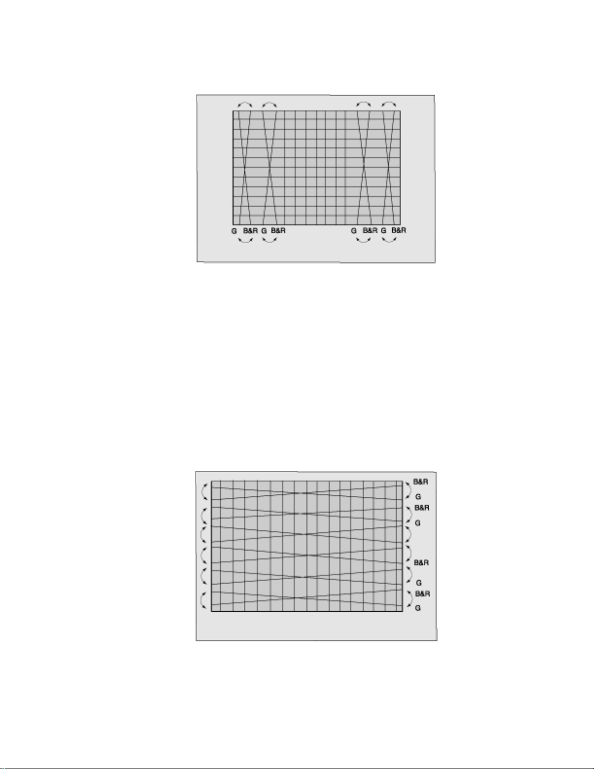
YH Adjustment
(VR2 for vertical dynamic convergence)
1. Apply a crosshatch pattern.
2. Adjust contrast and brightness customer controls to obtain a correct picture.
3. With a driver Adjust VR2 (located in deflection yoke board to obtain a proper corvergence at left
http://tsn.pstc.panasonic.com/viewing/NA/CT-36SL13G/SVC/s1201000000.html (1 of 3)05.12.2008 0:02:00
Page 44
http://tsn.pstc.panasonic.com/viewing/NA/CT-36SL13G/SVC/s1201000000.html
and right side of the screen.
VR2 adjustment (YH)
XV Adjustment (precise adjustment)
1. Apply a crosshatch pattern.
2. Adjust contrast and brightness customer controls to obtain a correct picture.
3. With a driver adjust the coil located in deflection yoke board to obtain a proper convergence
horizontally.
Xv adjustment
NOTE
Apply a red pattern and confirm purity, if purity is poor, repeat purity adjustments.
http://tsn.pstc.panasonic.com/viewing/NA/CT-36SL13G/SVC/s1201000000.html (2 of 3)05.12.2008 0:02:00
Page 45

http://tsn.pstc.panasonic.com/viewing/NA/CT-36SL13G/SVC/s1201000000.html
TOP PREVIOUS NEXT
http://tsn.pstc.panasonic.com/viewing/NA/CT-36SL13G/SVC/s1201000000.html (3 of 3)05.12.2008 0:02:00
Page 46

http://tsn.pstc.panasonic.com/viewing/NA/CT-36SL13G/SVC/s1202000000.html
12.2 Permalloy convergence corrector strip (Part
No. 0FMK014ZZ)
TOP PREVIOUS NEXT
This strip is used in some sets to match the yoke and CRT for optimum convergence. If the yoke or CRT
is replaced, the strip may not be required.
First converge the set without the strip and observe the corners.
First converge the set without the strip and observe the corners.
If correction is needed:
1. Place strip between CRT and yoke, in quadrant needing correction. Slowly move it around for
desired results.
2. Press adhesive tightly to the CRT and secure with tape.
TOP PREVIOUS NEXT
http://tsn.pstc.panasonic.com/viewing/NA/CT-36SL13G/SVC/s1202000000.html05.12.2008 0:02:03
Page 47

http://tsn.pstc.panasonic.com/viewing/NA/CT-36SL13G/SVC/s1203000000.html
12.3 DAF adjustment
(Dynamic focus adjustment)
TOP PREVIOUS NEXT
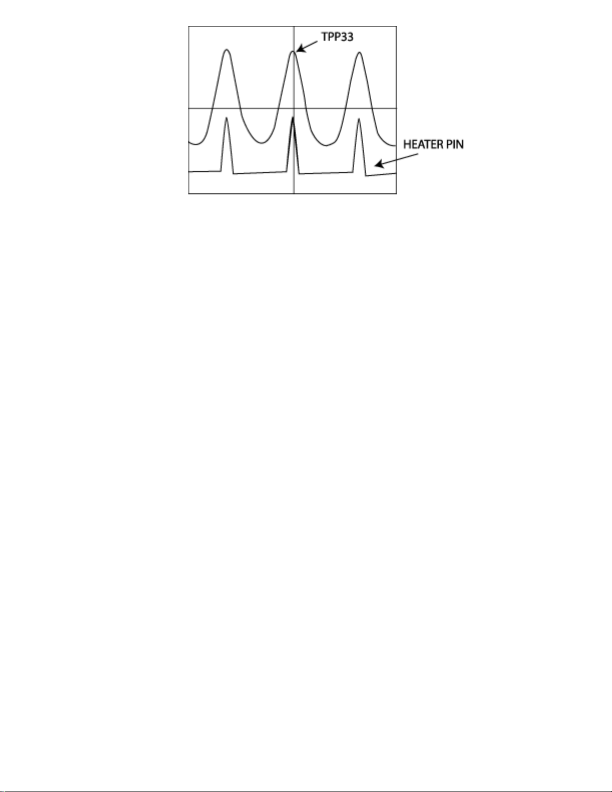
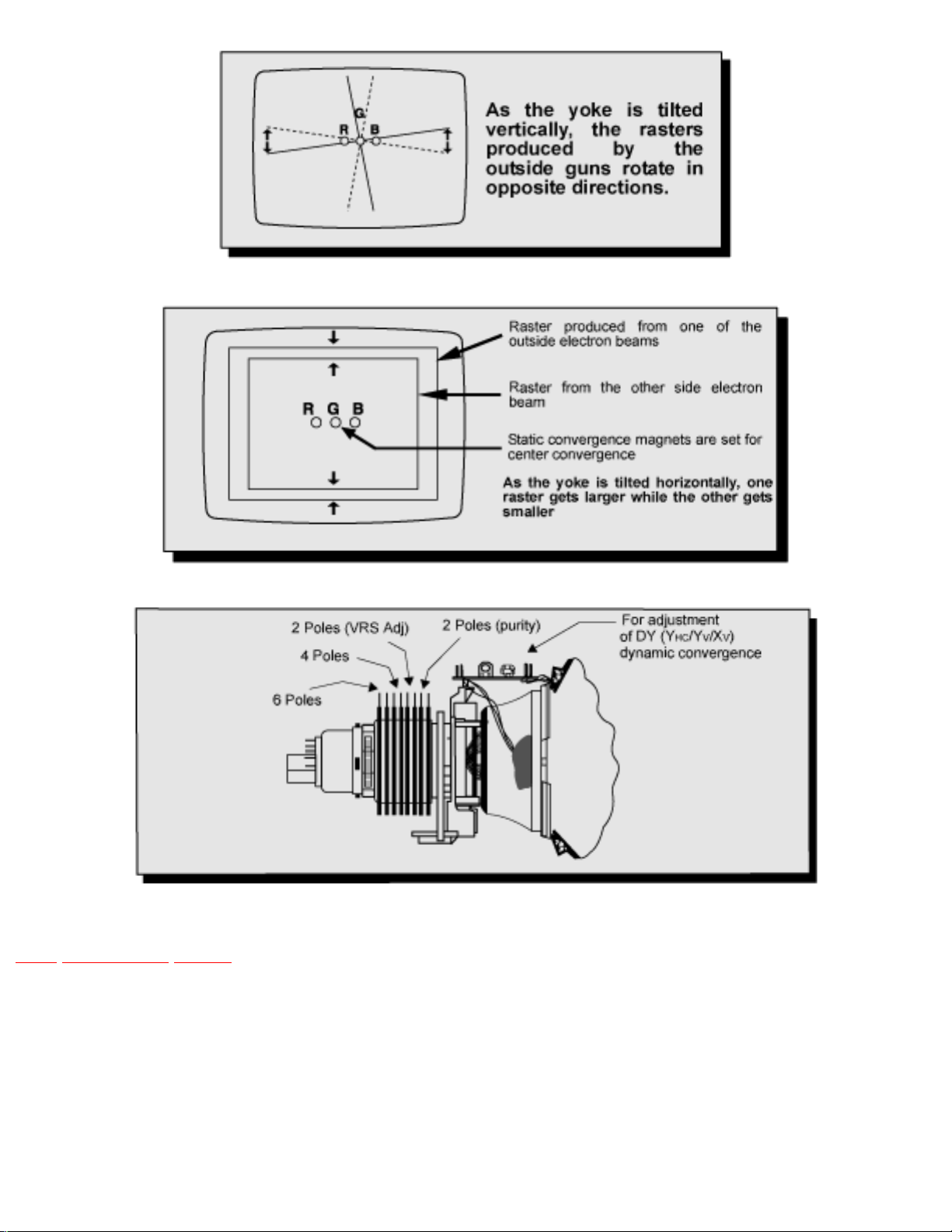
The purpose of this adjustment is to move the focus in the picture, so the focus is in balance in the whole
picture (same level). Perform this adjustment as a visual adjustment, centering both waveforms, repeat
adjustment until best adjustment isobtained.
PREPARATION
1. Picture settings normalized.
PREPARATION
1. Apply a crosshatch pattern.
2. Connect channel one of the oscilloscope with 100x1 probe to DAF OUT to TPP33 or TPD40 (DBoard).
3. Connect channel two of the oscilloscope with 10x1 probe to HEATER (L-Board).
4. If the the waveforms position are vercally different, adjust (HDAFP) DATA so that become the
same position.
NOTE
Both waveforms should be centered. Upper waveform could be different depending on the
pattern applied
DAF adjustment
http://tsn.pstc.panasonic.com/viewing/NA/CT-36SL13G/SVC/s1203000000.html (1 of 3)05.12.2008 0:02:09
Page 48
http://tsn.pstc.panasonic.com/viewing/NA/CT-36SL13G/SVC/s1203000000.html
5. Adjust “HDAFW” until TPP33 or TPD40 is 1.6_KVpp ±50Vpp
Other method (DAF adjustment)
PREPARATION
1. Picture settings normalized.
PROCEDURE
1. Apply a crosshatch pattern.
2. Put a mark in the focus control (on fly-back), so the control can be put back in the original
position.
3. Turn the focus control (fly-back) fully, so the image is out focus.
4. Then in service mode adjust (HDAFS) DATA, so the focus is moving from side to side in the
picture.
5. Adjust (HDAFS) DATA so the picture looks in balance in left and right.
6. Turn focus (fly-back) control back to its original position.
NOTE
Repeat adjustment until best adjustment is obtained. For best adjustment, use oscilloscope as
described in previous adjustment method.
http://tsn.pstc.panasonic.com/viewing/NA/CT-36SL13G/SVC/s1203000000.html (2 of 3)05.12.2008 0:02:09
Page 49
http://tsn.pstc.panasonic.com/viewing/NA/CT-36SL13G/SVC/s1203000000.html
TOP PREVIOUS NEXT
http://tsn.pstc.panasonic.com/viewing/NA/CT-36SL13G/SVC/s1203000000.html (3 of 3)05.12.2008 0:02:10
Page 50

http://tsn.pstc.panasonic.com/viewing/NA/CT-36SL13G/SVC/s1300000000x.html
13 Service mode (electronic adjustments)
TOP PREVIOUS NEXT
This receiver has electronic technology using the IC bus concept. It performs as a control function and it
replaces many mechanical controls. Instead of adjusting mechanical controls individually, many of the
control functions are now performedby using “on screen display menu”. (The service adjustment mode).
NOTE
It is suggested that the technician reads all the way through and understand the following procedure for
entering/exiting the service adjustment mode; then proceed with the instructions working with the
receiver. When becoming familiarwith the procedure, the flow chart for service mode may be used as a
quick guide.
Quick entry to service mode
When minor adjustments need to be done to the electronic controls, the method of entering the service
mode without removal of the cabinet back is as follows using the remote control:
1. Select SET-UP icon and select CABLE mode.
2. Select TIMER icon and set SLEEP time for 30 Min.
3. Press “ACTION” twice to exit menus.
4. Tune to the channel 124.
5. Adjust VOLUME to minimum (0).
6. Press VOL → (decrease) on receiver. Red “CHK” appears in upper corner.
To toggle between aging and service modes:
While the “CHK” is displayed on the left top corner of the CRT, pressing “ACTION” and
“VOL” UP on the TV simultaneously will toggle between the modes. Red “CHK” for serviceand
yellow “CHK” for aging.
7. Press POWER on the remote control to display the service adjustment modes menu, select
http://tsn.pstc.panasonic.com/viewing/NA/CT-36SL13G/SVC/s1300000000x.html (1 of 3)05.12.2008 0:02:15
Page 51
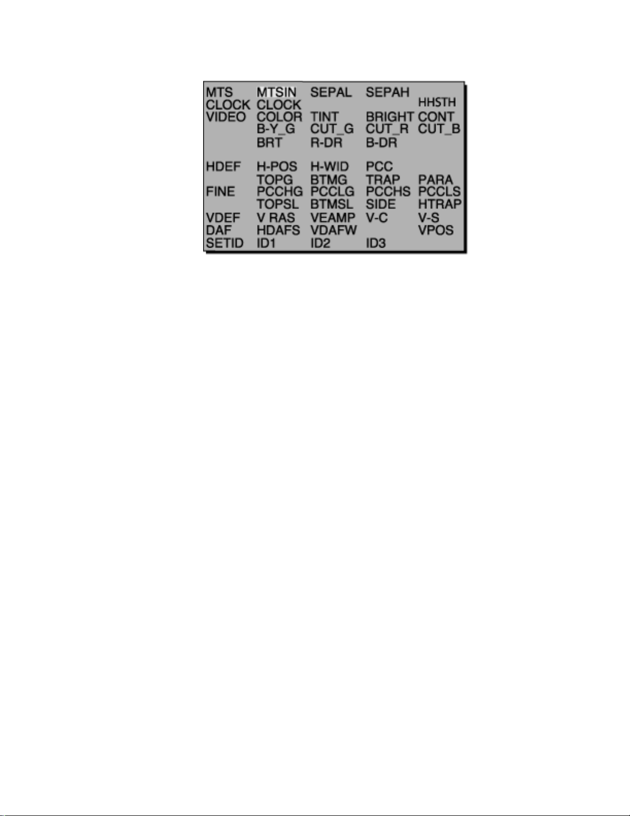
http://tsn.pstc.panasonic.com/viewing/NA/CT-36SL13G/SVC/s1300000000x.html
adjustment by pressing the volume right/left buttons and channel up/down buttons on the remote
and ACTION to enter the adjustment.
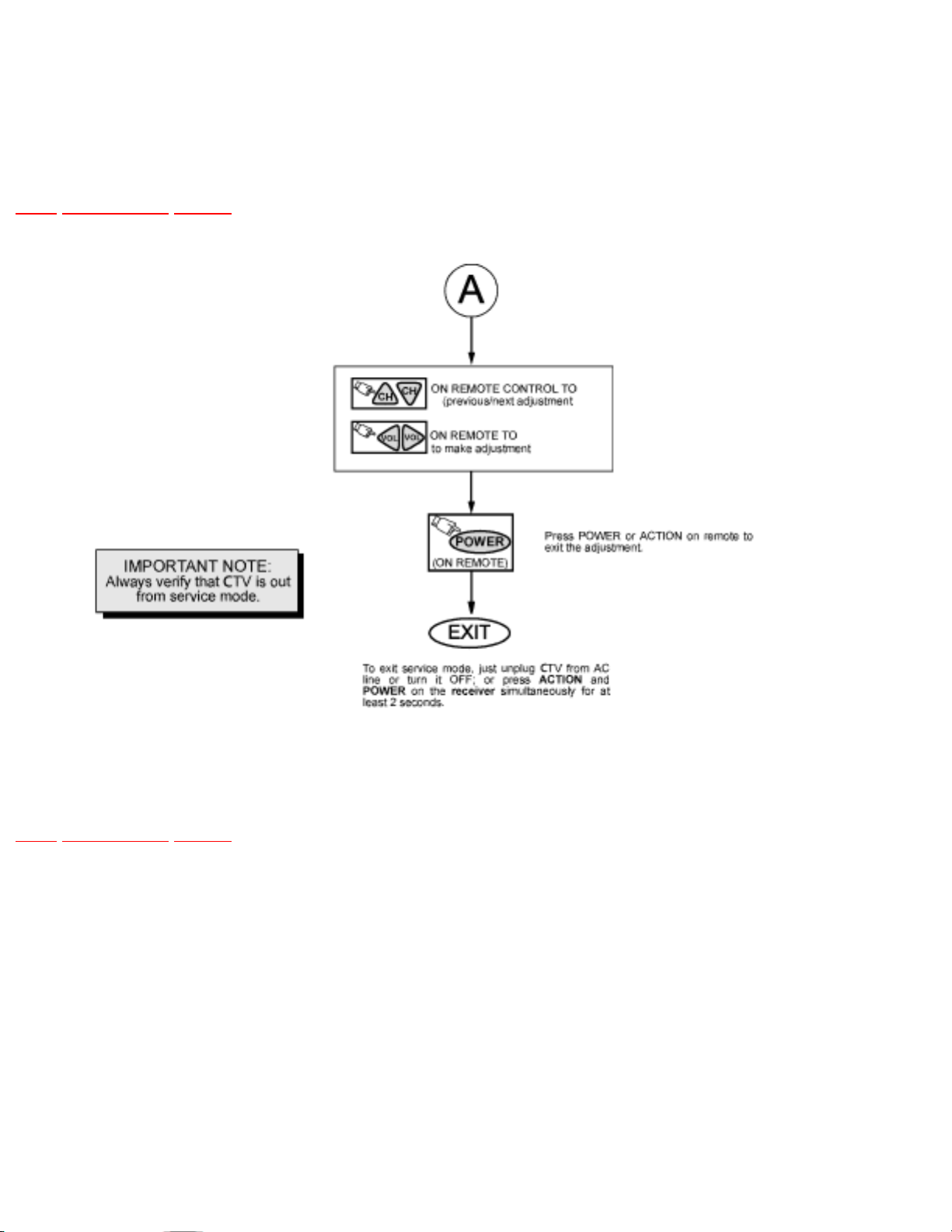
Exiting the service mode:
This TV goes out from service mode when it is unplugged or turned OFF. To exit the service mode, turn
the TV OFF from or unplug the TV from A.C.
Other method
Press ACTION and POWER on the receiver simultaneously for at least 2 seconds.
The receiver momentarily shuts off; then comes back on tuned to channel 3 with a preset level of sound.
Any programmed channels, channels caption data and some others user defined settings will be erased
when exited by pressing ACTION and POWER on receiver.
IMPORTANT NOTE
Always check that the TV exits the service mode.
To confirm colors
When in service mode (red “CHK” is displayed) press RECALL on the remote control to enter the
purity field check mode
http://tsn.pstc.panasonic.com/viewing/NA/CT-36SL13G/SVC/s1300000000x.html (2 of 3)05.12.2008 0:02:15
Page 52
http://tsn.pstc.panasonic.com/viewing/NA/CT-36SL13G/SVC/s1300000000x.html
Entering service mode (open-back method)
While the receiver is connected and operating in normal mode, momentarily short test point FA1 (TP1
pin 2) to cold ground (TP1 pin 3).
The receiver enters the aging mode.
Yellow letters “CHK” appear in the upper left corner of the screen.
(The volume right/left and channel up/down will adjust rapidly).
Note:
If service mode is accessed by this method be sure to reset the set after service is performed.
13.1 Service adjustment default values for items
13.2 Instructional flow chart for service mode
13.3 Instructional flow chart for service mode (continued).
TOP PREVIOUS NEXT
http://tsn.pstc.panasonic.com/viewing/NA/CT-36SL13G/SVC/s1300000000x.html (3 of 3)05.12.2008 0:02:15
Page 53

http://tsn.pstc.panasonic.com/viewing/NA/CT-36SL13G/SVC/s1301000000.html
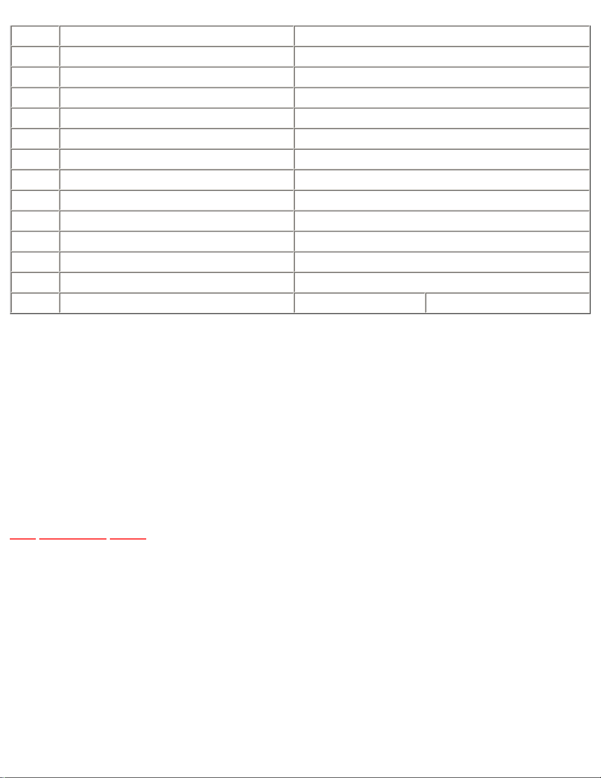
13.1 Service adjustment default values for items
TOP PREVIOUS NEXT
NAME DESCRIPTION REGISTER VALUE
CT-36SL13G, CT-32SL13G CT-36SC13G, CT-32SC13G, CT-
3653G
MTSIN MTS INPUT LEVEL 1D
SEPAL MTS LOW LEVEL SEPARATION 06
SEPAH MTS HIGH LEVEL SEPARATION 1F
CLOCK CLOCK 141
HHSTH HHS VOLTAGE LEVEL REFERENCE EE
COLOR COLOR 20
TINT TINT 4B
BRIGH SUB-BRIGHTNESS 22
CONT SUB-CONTRAST 88
B-Y_G MAGENTA TINT ADJ 80
CUT_G GREEN CUT-OFF DF
CUT_R RED CUT-OFF BA
CUT_B BLUE CUT-OFF CF
BRT BRIGHT 22
R-DR RED DRIVE 7A
B-DR BLUE DRIVE 77
H-POS HORIZONTAL POSITIONING 7F
H-WID HORIZONTAL WIDTH 38
PCC PINCUSHION CORRECTION 27
TOPG TOP CORNER PINCUSHION 15
BTMG BOTTOM CORNER PINCUSHION 15
TRAP TRAPEZOID 84
PARA PARALLELOGRAM 13
PCCHG PINCUSHION HIGH 07
PCCLG PINCUSHION LOW 04
PCCHS PINCUSHION HIGH 0F
PCCLS PINCUSHION LOW 0F
http://tsn.pstc.panasonic.com/viewing/NA/CT-36SL13G/SVC/s1301000000.html (1 of 2)05.12.2008 0:02:20
Page 54
http://tsn.pstc.panasonic.com/viewing/NA/CT-36SL13G/SVC/s1301000000.html
TOPSL TOP CORNER PINCUSHION SLICE LEVEL 05
BTMSL BOTTOM CORNER PINCUSHION SLICE LEVEL 04
SIDE E-W PINCUSHION ADJUSTMENT 35
HTRAP HORIZONTAL TRAPEZOID 10
VRAS VERTICAL POSITION 41
VEAMP VERTICAL SIZE BB
V-C VERTICAL LINEARITY 21
V-S VERTICAL S CORRECTION 11
HDAFP DAF C4
HDAFW DAF 88
VPOS VERTICAL POSITIONING 7E
ID1* ID SWITCH 1 FC
ID2* ID SWITCH 2 7F
ID3* ID SWITCH 3 7B 48
IMPORTANT:
These table values are approximated and could change due to variation of electrical characteristics in
each set, except for the ID switch values.
*Note:
The correspondent ID switch (ID1, ID2, ID3) data configuration should not be modified in any way. If
EEPROM circuit needs to be replaced, these ID values should be configured according with this table.
TOP PREVIOUS NEXT
http://tsn.pstc.panasonic.com/viewing/NA/CT-36SL13G/SVC/s1301000000.html (2 of 2)05.12.2008 0:02:20
Page 55
http://tsn.pstc.panasonic.com/viewing/NA/CT-36SL13G/SVC/s1302000000.html
13.2 Instructional flow chart for service mode
TOP PREVIOUS NEXT
http://tsn.pstc.panasonic.com/viewing/NA/CT-36SL13G/SVC/s1302000000.html (1 of 2)05.12.2008 0:02:24
Page 56
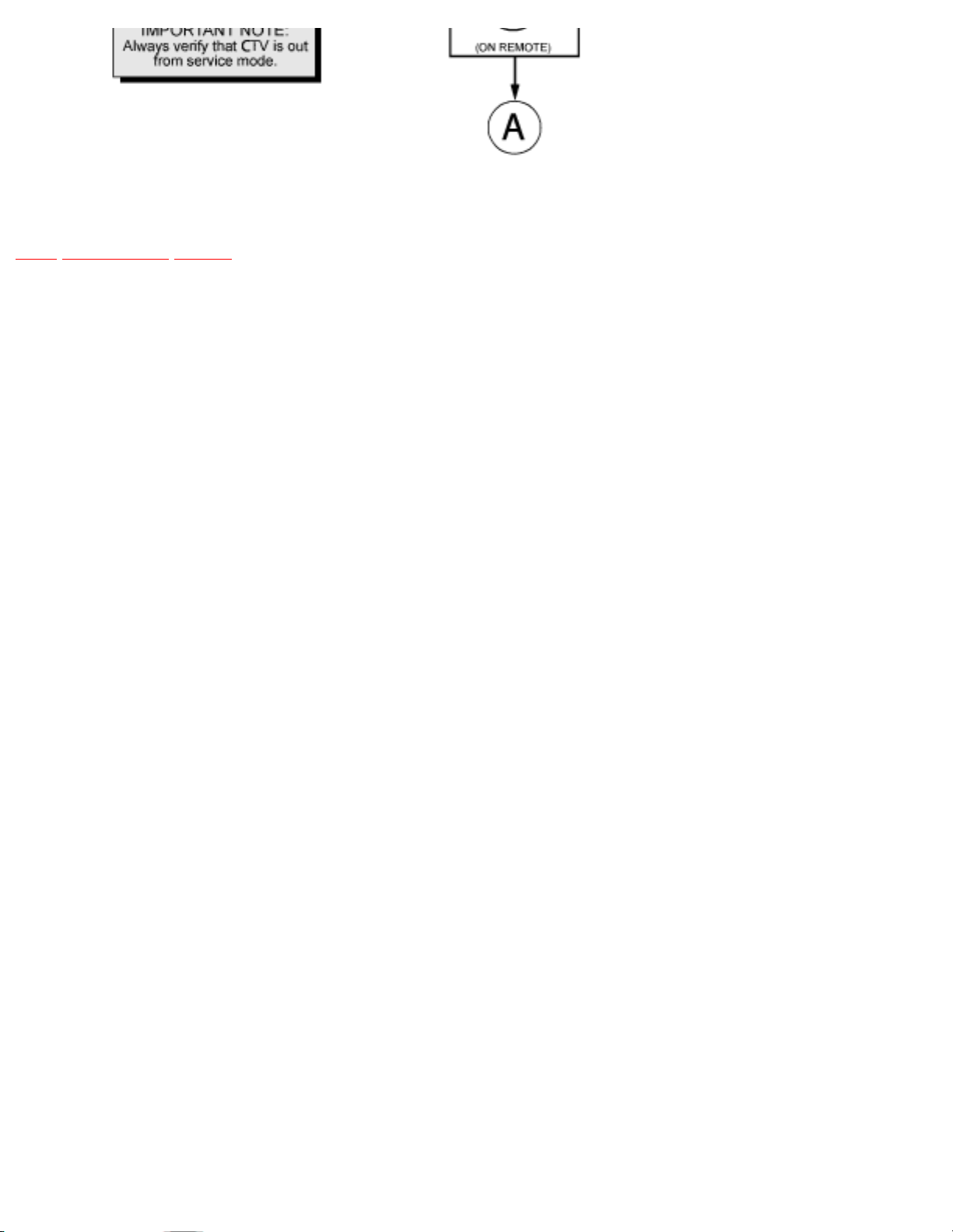
http://tsn.pstc.panasonic.com/viewing/NA/CT-36SL13G/SVC/s1302000000.html
TOP PREVIOUS NEXT
http://tsn.pstc.panasonic.com/viewing/NA/CT-36SL13G/SVC/s1302000000.html (2 of 2)05.12.2008 0:02:24
Page 57
http://tsn.pstc.panasonic.com/viewing/NA/CT-36SL13G/SVC/s1303000000.html
13.3 Instructional flow chart for service mode
(continued).
TOP PREVIOUS NEXT
TOP PREVIOUS NEXT
http://tsn.pstc.panasonic.com/viewing/NA/CT-36SL13G/SVC/s1303000000.html05.12.2008 0:02:28
Page 58

http://tsn.pstc.panasonic.com/viewing/NA/CT-36SL13G/SVC/s1400000000x.html
14 Service adjustments (electronic controls)
TOP PREVIOUS NEXT
NOTE
Please correlate with available pattern on all adjustments
14.1 Sub-Brightness and ContrastService DAC adjustment (BRIGH, CONT)
14.2 Color output adjustmentService DAC adjustment (COLOR, TINT)
14.3 Color output adjustmentService DAC adjustment(COLOR, TINT, B-Y_G)
14.4 Color temperature adjustment(B/W Tracking)Service DAC Adjust.(CUT R) (CUT G) (CUT B) (R
DR) (B DR)
14.5 Deflection adjustments
14.5.1 H-Center adjustment
14.5.2 H-Width adjustment
14.5.3 Trapezoid adjustment
14.5.4 Parallelogram adjustment
14.5.5 E-W PCC balance adjustment
14.5.6 Vertical linearity(V-C), V-Size and V-Position adjustment
14.5.7 V-S Correction adjustment
14.6 MTS circuit adjustments
14.7 Clock adjustment (CLOCK)
http://tsn.pstc.panasonic.com/viewing/NA/CT-36SL13G/SVC/s1400000000x.html (1 of 2)05.12.2008 0:02:33
Page 59

http://tsn.pstc.panasonic.com/viewing/NA/CT-36SL13G/SVC/s1400000000x.html
14.8 Service Adjustments Mechanical Controls
TOP PREVIOUS NEXT
http://tsn.pstc.panasonic.com/viewing/NA/CT-36SL13G/SVC/s1400000000x.html (2 of 2)05.12.2008 0:02:33
Page 60

http://tsn.pstc.panasonic.com/viewing/NA/CT-36SL13G/SVC/s1401000000.html
14.1 Sub-Brightness and Contrast
Service DAC adjustment (BRIGH, CONT)
TOP PREVIOUS NEXT
Adjustment of this control is important for setting proper operation of customer brightness and picture
controls. Do not adjust the SCREEN VR after the sub-brightness is set.
This adjustment is factory set. Do not adjust unless repairs are made to associated circuit, the CRT
Board or when the CRT is replaced.
Preparation
1. Apply a black and white pattern.
Note:
If a black and withe pattern is not available, a color bar pattern with no color can be used
following the same procedure; the waveform will be different
2. Set the PICTURE control to the maximum.
3. Set COLOR control to minimum (no color on picture).
4. Set the BRIGHTNESS control to the center.
5. Set the SHARPNESS control to the center.
6. Connect the oscilloscope to TP35.
Procedure
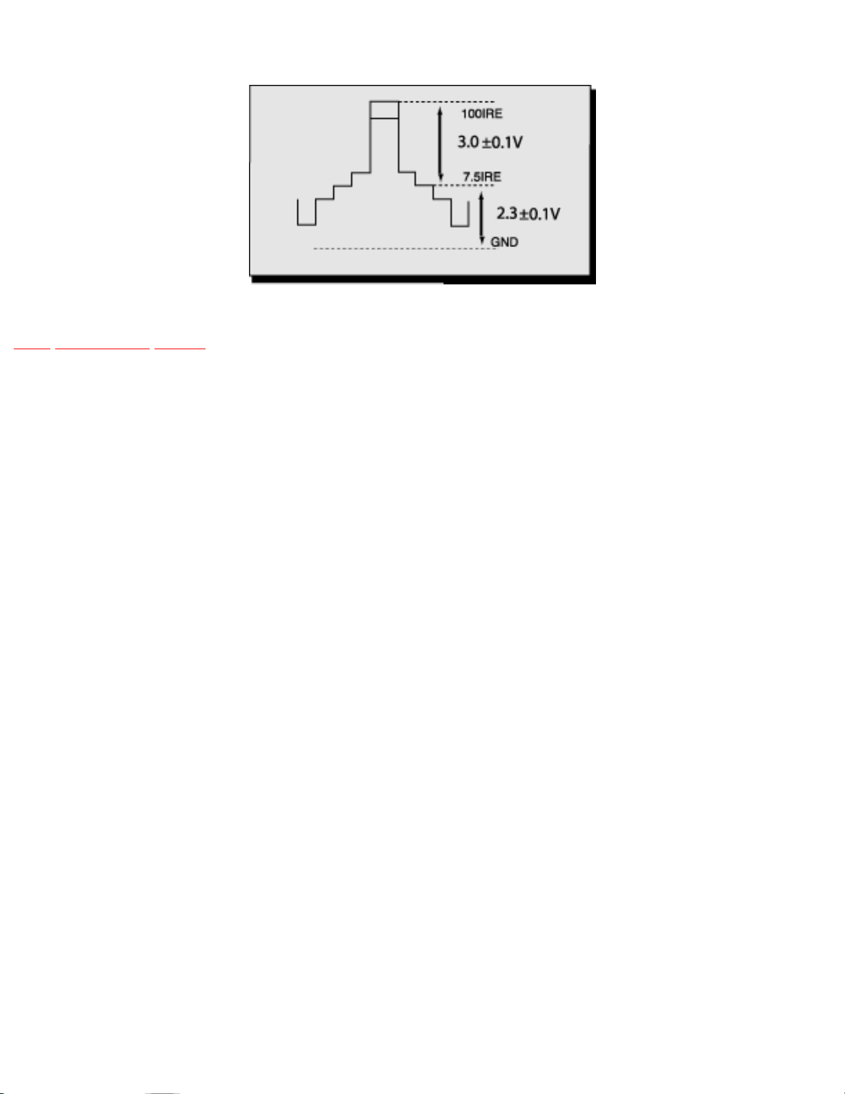
1. In the service mode, select DAC for brightness adjustment “BRIGH”, and adjust data to obtain
2.3±0.1V between 7.5IRE and GND level at TP35. (See waveform detail).
2. In service mode, select DAC for contrast adjustment “CONT”, and adjust data to obtain 3.0±0.1V
between 7.5IRE and 100IRE level at TP35. (See waveform detail)
http://tsn.pstc.panasonic.com/viewing/NA/CT-36SL13G/SVC/s1401000000.html (1 of 2)05.12.2008 0:02:38
Page 61
http://tsn.pstc.panasonic.com/viewing/NA/CT-36SL13G/SVC/s1401000000.html
Waveform with black and white pattern applied
TOP PREVIOUS NEXT
http://tsn.pstc.panasonic.com/viewing/NA/CT-36SL13G/SVC/s1401000000.html (2 of 2)05.12.2008 0:02:38
Page 62

http://tsn.pstc.panasonic.com/viewing/NA/CT-36SL13G/SVC/s1402000000.html
14.2 Color output adjustment
Service DAC adjustment (COLOR, TINT)
TOP PREVIOUS NEXT
NOTE
if a rainbow pattern generator is available perform the following procedure; the next section describes
the procedure with no rainbow pattern.
Make sure that sub-contrast adjustment was finished prior to perform this adjustment.
Preparation
1. Normalize the picture settings.
2. Set the BRIGHTNESS control to minimum.
3. Set the COLOR control to the center.
4. Set the TINT control to the center.
5. Set the PICTURE control to the maximum.
6. Set the SHARPNESS control to the minimum.
Procedure
1. Apply a rainbow color bar pattern.
2. Connect the oscilloscope to TP37.
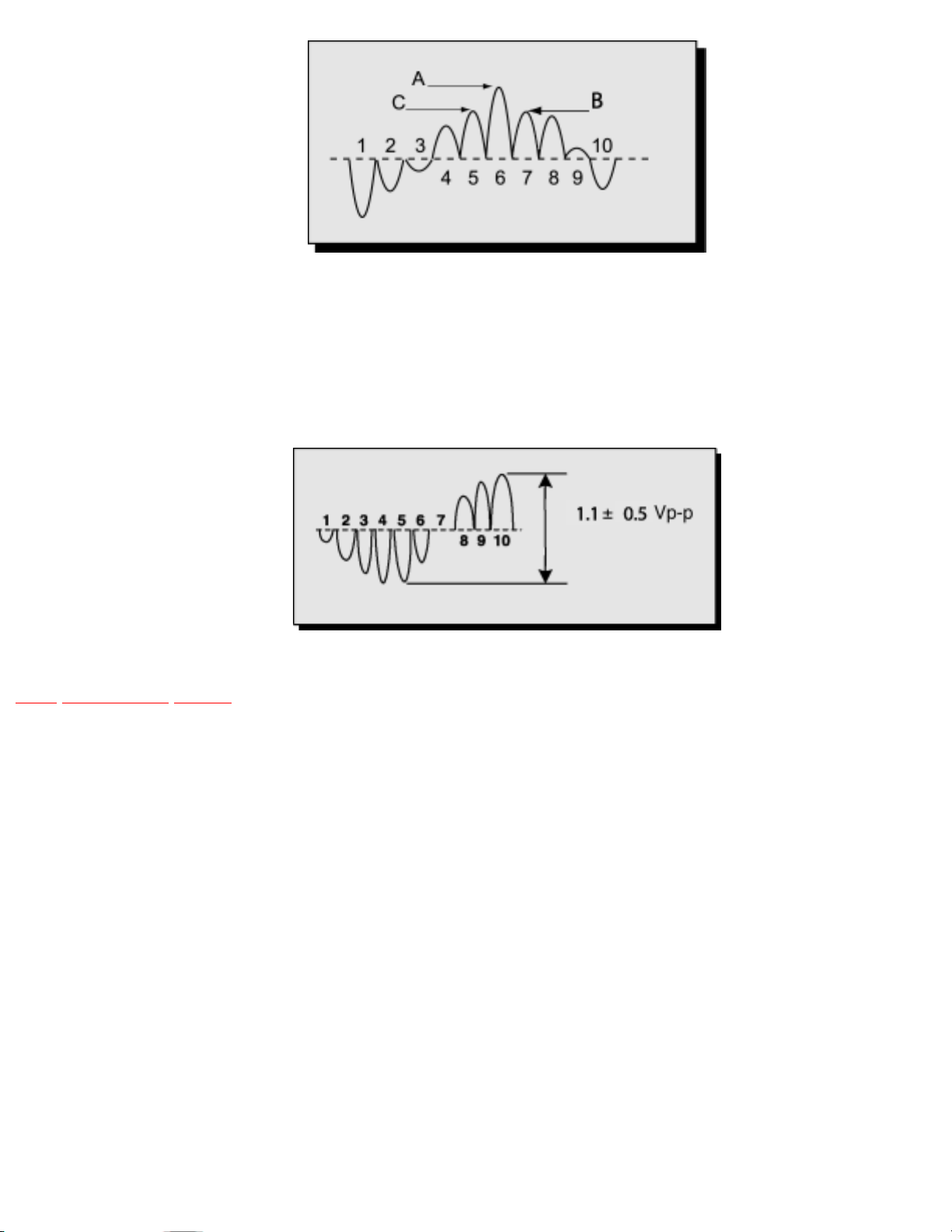
3. In service mode adjust “TINT” register until the waveform measured is as the one shown. Tint
level from C and B peaks must be almost in the same level and from A and C must be 0.35 Vpp.
TP37 Waveform.
http://tsn.pstc.panasonic.com/viewing/NA/CT-36SL13G/SVC/s1402000000.html (1 of 2)05.12.2008 0:02:45
Page 63
http://tsn.pstc.panasonic.com/viewing/NA/CT-36SL13G/SVC/s1402000000.html
4. Connect the oscilloscope to TP35 and GND.
5. Adjust “COLOR” register so that the amplitude is 1.1±0.5Vpp.
TP35 Waveform.
TOP PREVIOUS NEXT
http://tsn.pstc.panasonic.com/viewing/NA/CT-36SL13G/SVC/s1402000000.html (2 of 2)05.12.2008 0:02:45
Page 64

http://tsn.pstc.panasonic.com/viewing/NA/CT-36SL13G/SVC/s1403000000.html
14.3 Color output adjustment
Service DAC adjustment
(COLOR, TINT, B-Y_G)
TOP PREVIOUS NEXT
NOTE
Color and tint adjustment sets the reference settings for the user controls; It is important to read the
procedures.
(NO RAINBOW PATTERN)
Make sure that sub-contrast adjustment was finished prior to perform this adjustment
PREPARATION
Normalize the picture settings.
PROCEDURE
1. Apply a color bar pattern.
2. In service mode adjust “R DR” and “B DR” data to “80”.
3. In service mode adjust “TINT” data so that the color does not become greenish or redish.
4. In service mode adjust “COLOR” data so that the color level is not too high (saturated) or too
low (tending to black and white).
5. In service mode adjust “B-Y G” data so that blue and green seem natural.
6. Confirm that saturation and picture are normal (normal image).
7. If image is not satisfactory, repeat adjustment until the image is normal and natural.
NOTE
http://tsn.pstc.panasonic.com/viewing/NA/CT-36SL13G/SVC/s1403000000.html (1 of 2)05.12.2008 0:02:48
Page 65

http://tsn.pstc.panasonic.com/viewing/NA/CT-36SL13G/SVC/s1403000000.html
The image can be compared against other set to see the image quality.
TOP PREVIOUS NEXT
http://tsn.pstc.panasonic.com/viewing/NA/CT-36SL13G/SVC/s1403000000.html (2 of 2)05.12.2008 0:02:48
Page 66

http://tsn.pstc.panasonic.com/viewing/NA/CT-36SL13G/SVC/s1404000000.html
14.4 Color temperature adjustment
(B/W Tracking)
Service DAC Adjust.
(CUT R) (CUT G) (CUT B) (R DR) (B DR)
TOP PREVIOUS NEXT
Minor Touch-Up Method
OBSERVE low and high brightness areas of a B/W picture for proper tracking. Adjust only as required
for “good gray scale and warm highlights”.
1. LOW LIGHT areas - In service mode for making electronic adjustments, select CUT R, CUT G,
CUT B and adjust the picture for gray.
2. HIGH LIGHT areas - In service mode for making electronic adjustments, select drive R DR, B
DR and adjust the picture for warm whites.
Complete adjustment
PREPARATION
1. Turn the receiver “ON” and allow 30 minutes warm up at WHITE PATTERN.
2. Apply a color bar pattern (with no color).
3. Turn the SCREEN control (part of FBT T551) fully counterclockwise.
4. Preset the following service DACs for best results:
❍ BRIGH______________________1 D0
❍ CUT R______________________02 00
❍ CUT G______________________02 00
❍ CUT B______________________02 00
http://tsn.pstc.panasonic.com/viewing/NA/CT-36SL13G/SVC/s1404000000.html (1 of 3)05.12.2008 0:02:52
Page 67

http://tsn.pstc.panasonic.com/viewing/NA/CT-36SL13G/SVC/s1404000000.html
❍ R DR_______________________07 FF
❍ B DR_______________________07 FF
PROCEDURE
1. Connect the oscilloscope to KG (CRT-Board).
2. In service mode for making electronic adjustment, select “BRIGH” DAC to obtain 2.0±0.05V DC.
3. Press RECALL button on the remote control to collapse the raster. (service SW).
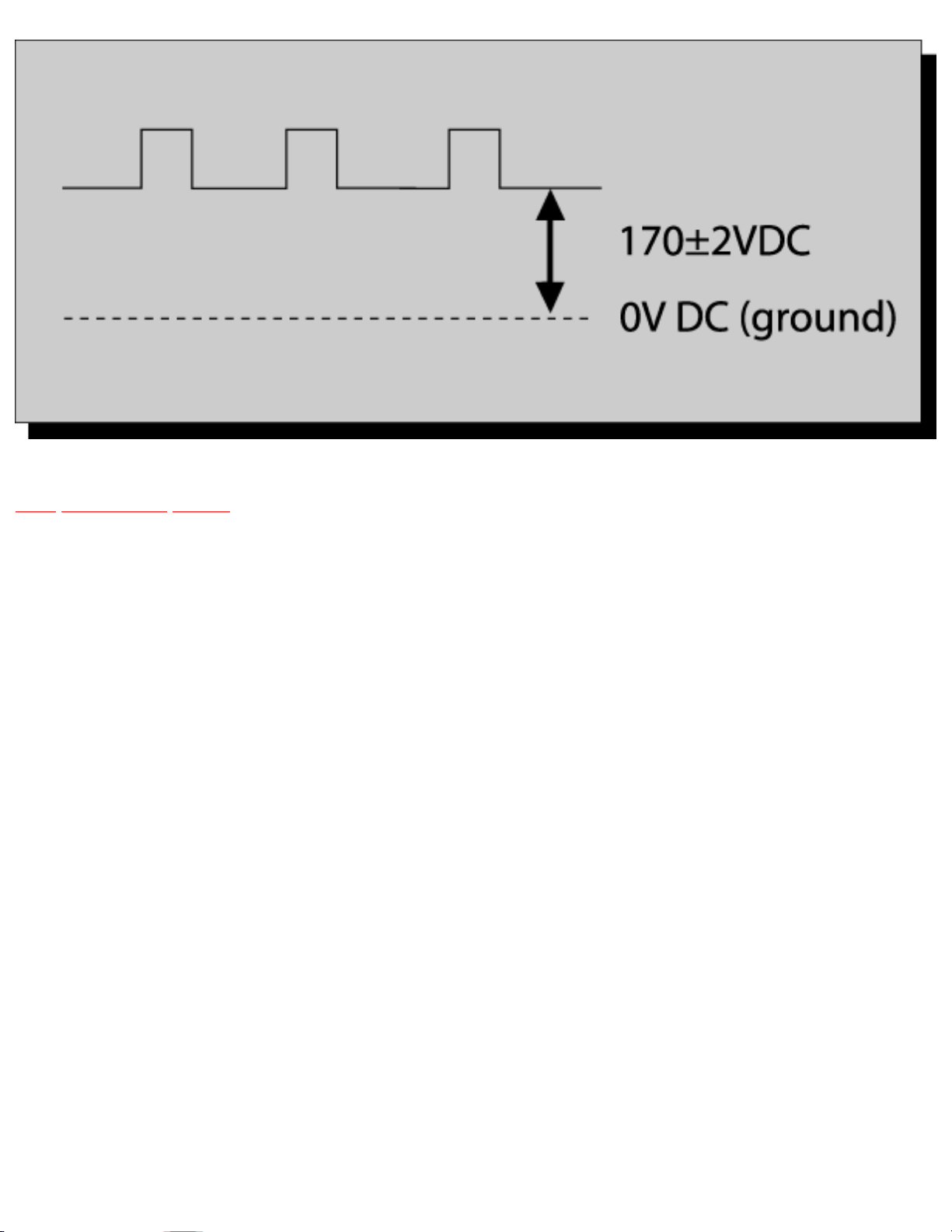
4. Connect oscilloscope to KG on C-Board and adjust service mode “CUT-G” DAC until 170±2V
above DC ground is measured
5. Remove the probe from KG.
6. Turn screen clockwise slowly until color is slightly appeared.
7. Then adjust “CUT R” and “CUT B” until line becomes white.
8. Press RECALL button on the remote to restore the raster.
9. Adjust “R DR” and “B DR” so the white seems like white and black like black.
10. Apply a normal signal and confirm that the image is normal and a good gray scale
11. If correction is needed perform minor touch-up method.
http://tsn.pstc.panasonic.com/viewing/NA/CT-36SL13G/SVC/s1404000000.html (2 of 3)05.12.2008 0:02:52
Page 68
http://tsn.pstc.panasonic.com/viewing/NA/CT-36SL13G/SVC/s1404000000.html
TOP PREVIOUS NEXT
http://tsn.pstc.panasonic.com/viewing/NA/CT-36SL13G/SVC/s1404000000.html (3 of 3)05.12.2008 0:02:52
Page 69

http://tsn.pstc.panasonic.com/viewing/NA/CT-36SL13G/SVC/s1405000000.html
14.5 Deflection adjustments
TOP PREVIOUS NEXT
To reset deflection adjustments
To reset deflection adjustments to factory adjusted default, enter to service mode (with red CHK
displayed), press POWER button on remote to display the service menu, then press and hold RECALL
button for at least three seconds, a reset messagewill appear in the image.
Use this feature when deflection adjustment gets off adjustment to the point that it cannot be adjusted
back easily.
14.5.1 H-Center adjustment
14.5.2 H-Width adjustment
14.5.3 Trapezoid adjustment
14.5.4 Parallelogram adjustment
14.5.5 E-W PCC balance adjustment
14.5.6 Vertical linearity(V-C), V-Size and V-Position adjustment
14.5.7 V-S Correction adjustment
TOP PREVIOUS NEXT
http://tsn.pstc.panasonic.com/viewing/NA/CT-36SL13G/SVC/s1405000000.html05.12.2008 0:02:58
Page 70

http://tsn.pstc.panasonic.com/viewing/NA/CT-36SL13G/SVC/s1405010000.html
14.5.1 H-Center adjustment
TOP PREVIOUS NEXT
PREPARATION
1. Normalize the picture settings.
PROCEDURE
1. Apply a pattern that permits to center the picture.
2. If the horizontal center is not aligned, in service mode adjust “H POS” DATA to adjust the
horizontal center of the image to the CRT center.
3. Verify that horizontal width of the picture is in good balance.
4. The image can be compared to another TV adjusted
TOP PREVIOUS NEXT
http://tsn.pstc.panasonic.com/viewing/NA/CT-36SL13G/SVC/s1405010000.html05.12.2008 0:03:01
Page 71

http://tsn.pstc.panasonic.com/viewing/NA/CT-36SL13G/SVC/s1405020000.html
14.5.2 H-Width adjustment
TOP PREVIOUS NEXT
PREPARATION
1. Use a pattern that permits centering the image
2. Normalize the picture settings.
PROCEDURE
1. Adjust “H WID” DATA so that left width and right become in good balance (not too wide or
narrow).
TOP PREVIOUS NEXT
http://tsn.pstc.panasonic.com/viewing/NA/CT-36SL13G/SVC/s1405020000.html05.12.2008 0:03:05
Page 72
http://tsn.pstc.panasonic.com/viewing/NA/CT-36SL13G/SVC/s1405030000.html
14.5.3 Trapezoid adjustment
TOP PREVIOUS NEXT
PREPARATION
1. Apply a crosshatch pattern
2. Normalize the picture settings.
PROCEDURE
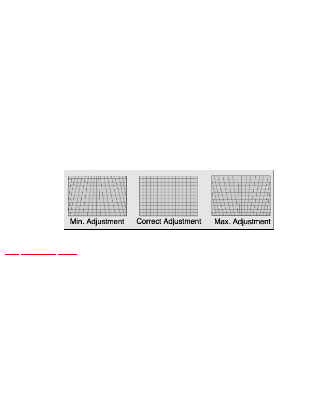
1. Enter service mode, select “TRAP” and adjust DATA so that lines at right and left are vertical
like a solid line
TOP PREVIOUS NEXT
http://tsn.pstc.panasonic.com/viewing/NA/CT-36SL13G/SVC/s1405030000.html05.12.2008 0:03:09
Page 73
http://tsn.pstc.panasonic.com/viewing/NA/CT-36SL13G/SVC/s1405040000.html
14.5.4 Parallelogram adjustment
TOP PREVIOUS NEXT
PREPARATION
1. Apply a crosshatch pattern
2. Normalize the picture settings.
PROCEDURE
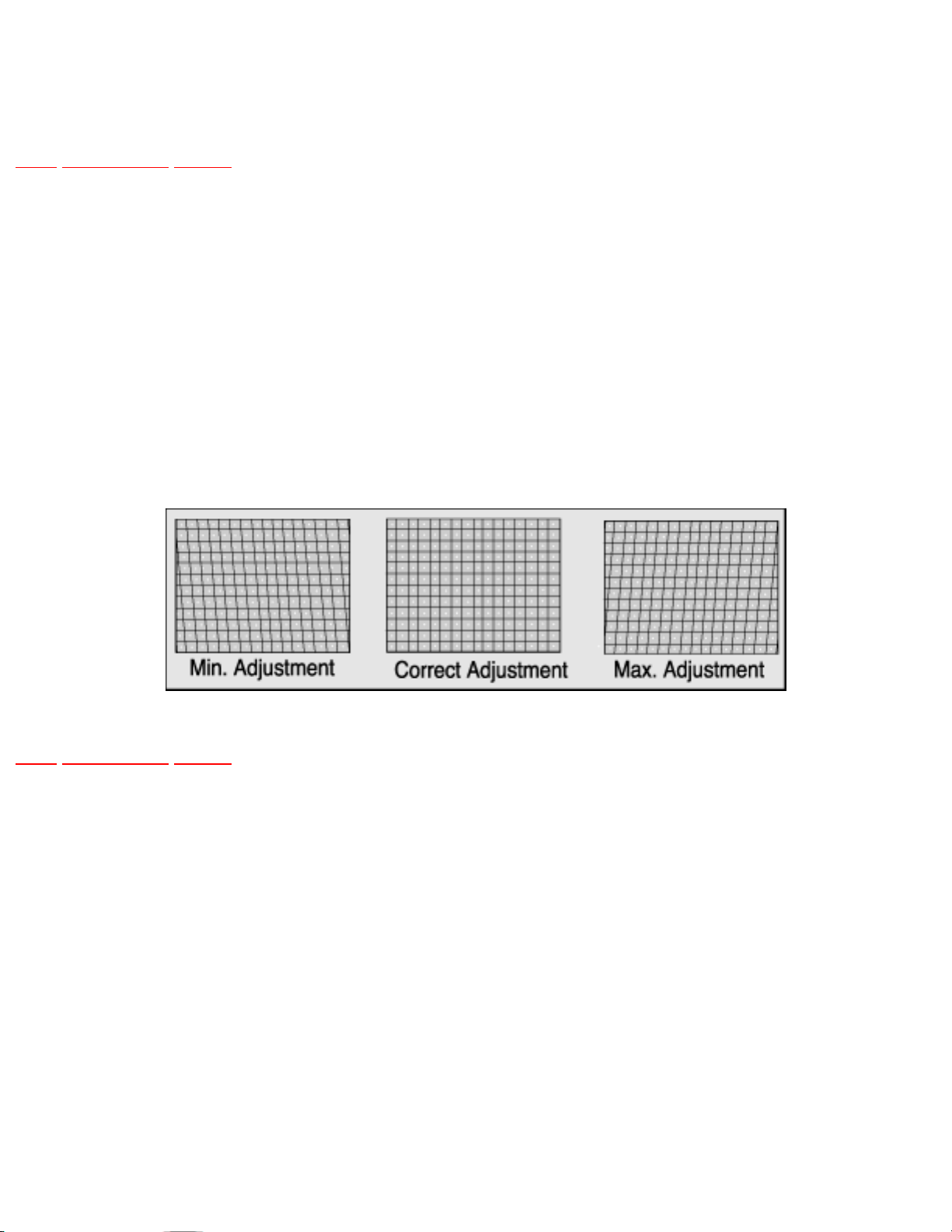
1. Enter service mode, select “PARA” and adjust so that the lines at right and left are vertical like
solid line.
TOP PREVIOUS NEXT
http://tsn.pstc.panasonic.com/viewing/NA/CT-36SL13G/SVC/s1405040000.html05.12.2008 0:03:13
Page 74
http://tsn.pstc.panasonic.com/viewing/NA/CT-36SL13G/SVC/s1405050000.html
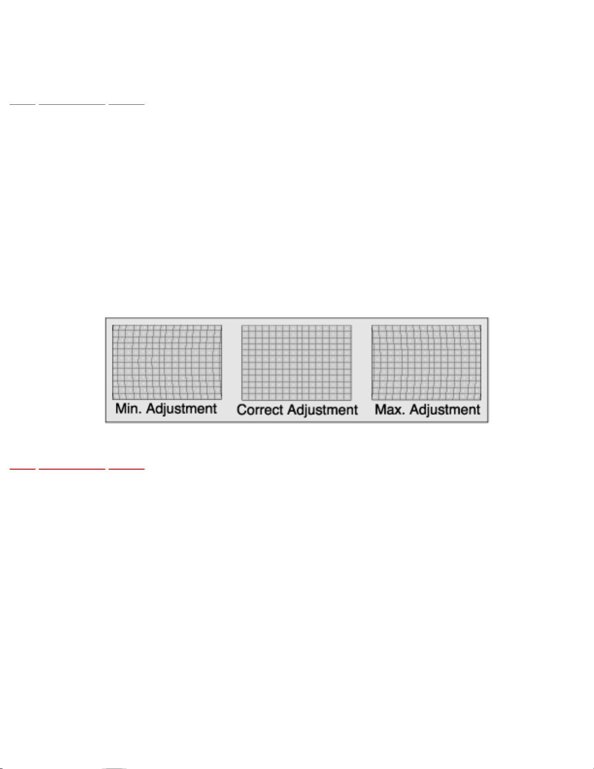
14.5.5 E-W PCC balance adjustment
TOP PREVIOUS NEXT
PREPARATION
1. Apply a crosshatch pattern
2. Normalize the picture settings.
PROCEDURE
1. Enter service mode, select “SIDE” and adjust so that lines at right and left are vertical like solid
line.
TOP PREVIOUS NEXT
http://tsn.pstc.panasonic.com/viewing/NA/CT-36SL13G/SVC/s1405050000.html05.12.2008 0:03:17
Page 75
http://tsn.pstc.panasonic.com/viewing/NA/CT-36SL13G/SVC/s1405060000.html
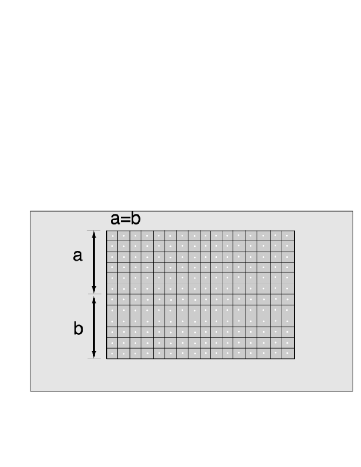
14.5.6 Vertical linearity(V-C), V-Size and V-Position
adjustment
TOP PREVIOUS NEXT
PREPARATION
1. Apply a crosshatch pattern
2. Normalize the picture settings.
PROCEDURE
1. Enter service mode, select DAC adjustment
“VRAS” and adjust monoscope pattern to the center vertical position of the CRT center mark.
2. Apply a monoscope pattern.
3. Confirm that center horizontal line is in center mark on CRT.
http://tsn.pstc.panasonic.com/viewing/NA/CT-36SL13G/SVC/s1405060000.html (1 of 2)05.12.2008 0:03:20
Page 76
http://tsn.pstc.panasonic.com/viewing/NA/CT-36SL13G/SVC/s1405060000.html
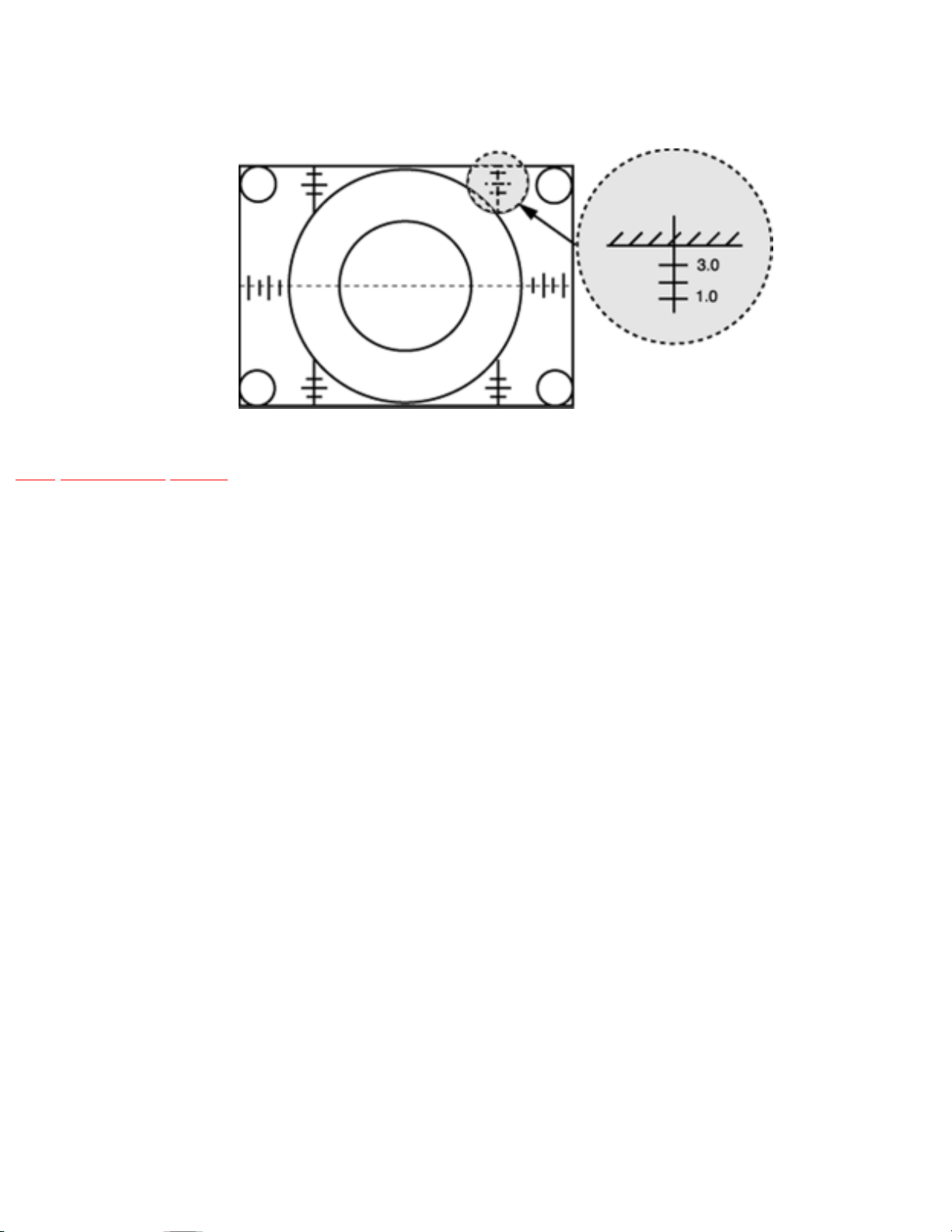
4. Adjust “VEAMP” register to correct vertical size.
Vertical centering adjustment.
TOP PREVIOUS NEXT
http://tsn.pstc.panasonic.com/viewing/NA/CT-36SL13G/SVC/s1405060000.html (2 of 2)05.12.2008 0:03:20
Page 77
http://tsn.pstc.panasonic.com/viewing/NA/CT-36SL13G/SVC/s1405070000.html
14.5.7 V-S Correction adjustment
TOP PREVIOUS NEXT
PREPARATION
1. Apply a crosshatch pattern
2. Normalize the picture settings.
PROCEDURE
1. Enter to service mode
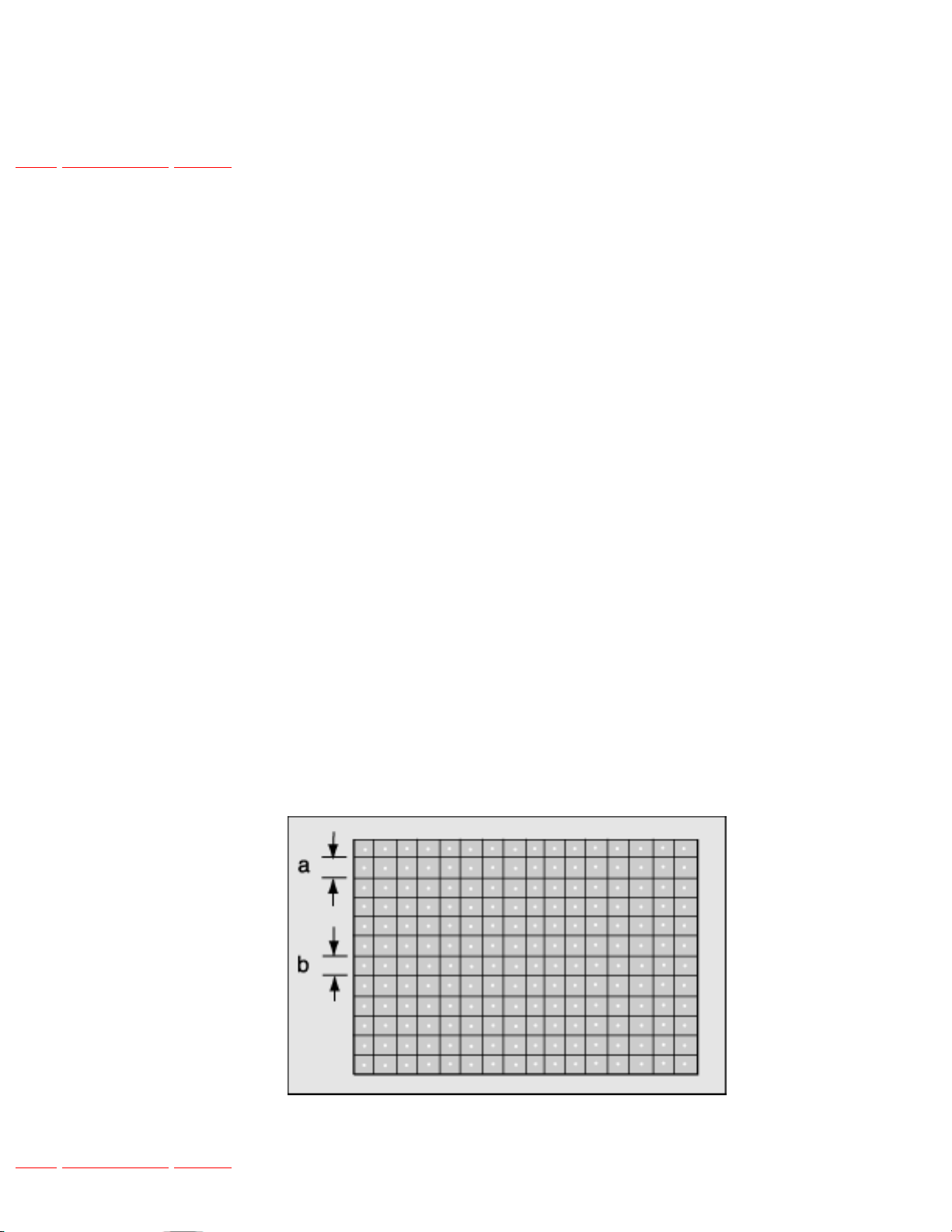
2. Check a and b sizes, If b-a < -1.5mm (in top & bottom extending case)
❍ Increase “V-S” DATA by one step
NOTE
Repeat “a” and “b” until b-a ± 1.5mm
3. Confirm to make outermost circle of monoscope pattern a correct circle
V-Adjustment
TOP PREVIOUS NEXT
http://tsn.pstc.panasonic.com/viewing/NA/CT-36SL13G/SVC/s1405070000.html05.12.2008 0:03:24
Page 78
http://tsn.pstc.panasonic.com/viewing/NA/CT-36SL13G/SVC/s1406000000.html
14.6 MTS circuit adjustments
TOP PREVIOUS NEXT
The MTS circuit adjustments require two steps:
1. Input level adjustment.
2. Stereo separation adjustment.
Input level adjustment
Service DAC adjustment (MTSIN)
PREPARATION
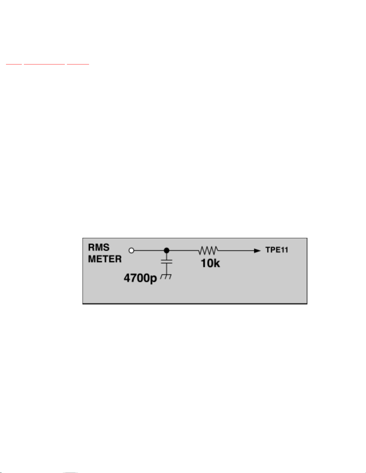
1. Connect an RMS meter with filter jig as shown in figure to TPE11.
Filter Jig
2. Connect an RF signal generator to the RF antenna input.
PROCEDURE
1. Apply the following signal from the RF signal generator:
❍ Video: 100 IRE flat field, 30% modulation.
❍ Audio: 300Hz, 100% modulation, monaural (70 ±5dB, 75Ω OPEN, P/S 10dB). Make sure
that the 75μs pre-emphasis is OFF.
2. Adjust the MTS input level adjustment “MTSIN” data until the RMS voltage measured is
http://tsn.pstc.panasonic.com/viewing/NA/CT-36SL13G/SVC/s1406000000.html (1 of 3)05.12.2008 0:03:31
Page 79

http://tsn.pstc.panasonic.com/viewing/NA/CT-36SL13G/SVC/s1406000000.html
130 ± 6.0mVrms.
Stereo separation adjustment (SEPAH)
PREPARATION
1. Connect an R.F. signal generator to the RF antenna input.
2. Connect a scope to TPA10.
PROCEDURE
1. Select stereo mode in audio menu
2. Apply the following signal from the RF signal generator:
❍ Video: 100 IRE flat field, 30% modulation.
❍ Audio: 300Hz, 30% modulation, stereo (left only) (70±5dB, 75Ω OPEN, P/S 10dB).
NOTE
After setting 30% modulation with P.L. SW and N.R. SW OFF, turn P.L. SW and N.R.
SW ON.
3. In service mode, adjust the MTS Low-Level separation adjustment “SEPAL” data until the
amplitude displayed on the scope is minimum.
4. Apply the following signal from the RF signal generator:
❍ Video: 100 IRE flat field, 30% modulation
❍ Audio: 3KHz, 30% modulation, stereo (left only) (70 ±5dB, 75Ω OPEN, P/S 10dB).
NOTE
After setting 30% modulation with P.L. SW and N.R. SW OFF, turn P.L. SW and N.R.
SW ON.
5. Adjust the MTS High-level separation adjustment “SEPAH” until the amplitude displayed on the
scope is minimum.
http://tsn.pstc.panasonic.com/viewing/NA/CT-36SL13G/SVC/s1406000000.html (2 of 3)05.12.2008 0:03:31
Page 80

http://tsn.pstc.panasonic.com/viewing/NA/CT-36SL13G/SVC/s1406000000.html
6. Repeat above steps 2 through 5 until the amplitude is at minimum for both signals.
TOP PREVIOUS NEXT
http://tsn.pstc.panasonic.com/viewing/NA/CT-36SL13G/SVC/s1406000000.html (3 of 3)05.12.2008 0:03:31
Page 81
http://tsn.pstc.panasonic.com/viewing/NA/CT-36SL13G/SVC/s1407000000.html
14.7 Clock adjustment (CLOCK)
TOP PREVIOUS NEXT
PREPARATION
Connect the frequency counter from TP017
(IC001 pin 79) to cold ground
PROCEDURE
1. Turn the receiver “OFF” with the A.C. power applied.
2. Measure TP017 (IC001 pin 79) for the frequency of the waveform and record the reading.
NOTE
3. TP017 (IC001 pin 79) measurement must have at least four digits of resolution following the
decimal point. Example: 000.0000
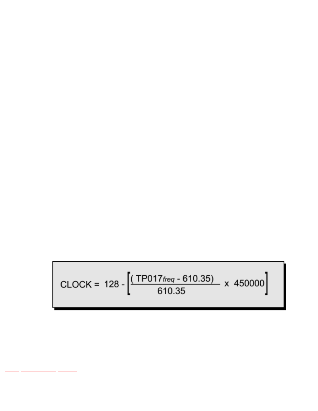
4. Place the receiver into service mode for making electronic adjustment, select the clock
adjustment DAC “CLOCK”.
5. Calculate and set “CLOCK” based on the following formula:
NOTE
TP017 (IC001 pin 79) measurement will not change regardless of the value stored in CLOCK.
TOP PREVIOUS NEXT
http://tsn.pstc.panasonic.com/viewing/NA/CT-36SL13G/SVC/s1407000000.html05.12.2008 0:03:36
Page 82

http://tsn.pstc.panasonic.com/viewing/NA/CT-36SL13G/SVC/s1408000000.html
14.8 Service Adjustments Mechanical Controls
TOP PREVIOUS NEXT
WIDTH CORRECTION ADJUSTMENT
Note
Perform this adjustment only when FBT is changed.
FOCUS (PART OF T551)
Preparation
Apply a crosshatch pattern with dots.
Procedure
1. Adjust the FOCUS VR to obtain the sharpest and clearest dot pattern.
❍ Adjust for best center.
❍ Adjust for best area between the center and top right corner.
TOP PREVIOUS NEXT
http://tsn.pstc.panasonic.com/viewing/NA/CT-36SL13G/SVC/s1408000000.html05.12.2008 0:03:40
Page 83

http://tsn.pstc.panasonic.com/viewing/NA/CT-36SL13G/SVC/s1500000000x.html
15 Identification of Components
TOP PREVIOUS NEXT
15.1 A-Board components
15.1.1 D-Board components
15.1.2 G-Board components
15.1.3 L-Board components
TOP PREVIOUS NEXT
http://tsn.pstc.panasonic.com/viewing/NA/CT-36SL13G/SVC/s1500000000x.html05.12.2008 0:03:49
Page 84
http://tsn.pstc.panasonic.com/viewing/NA/CT-36SL13G/SVC/s1501000000.html
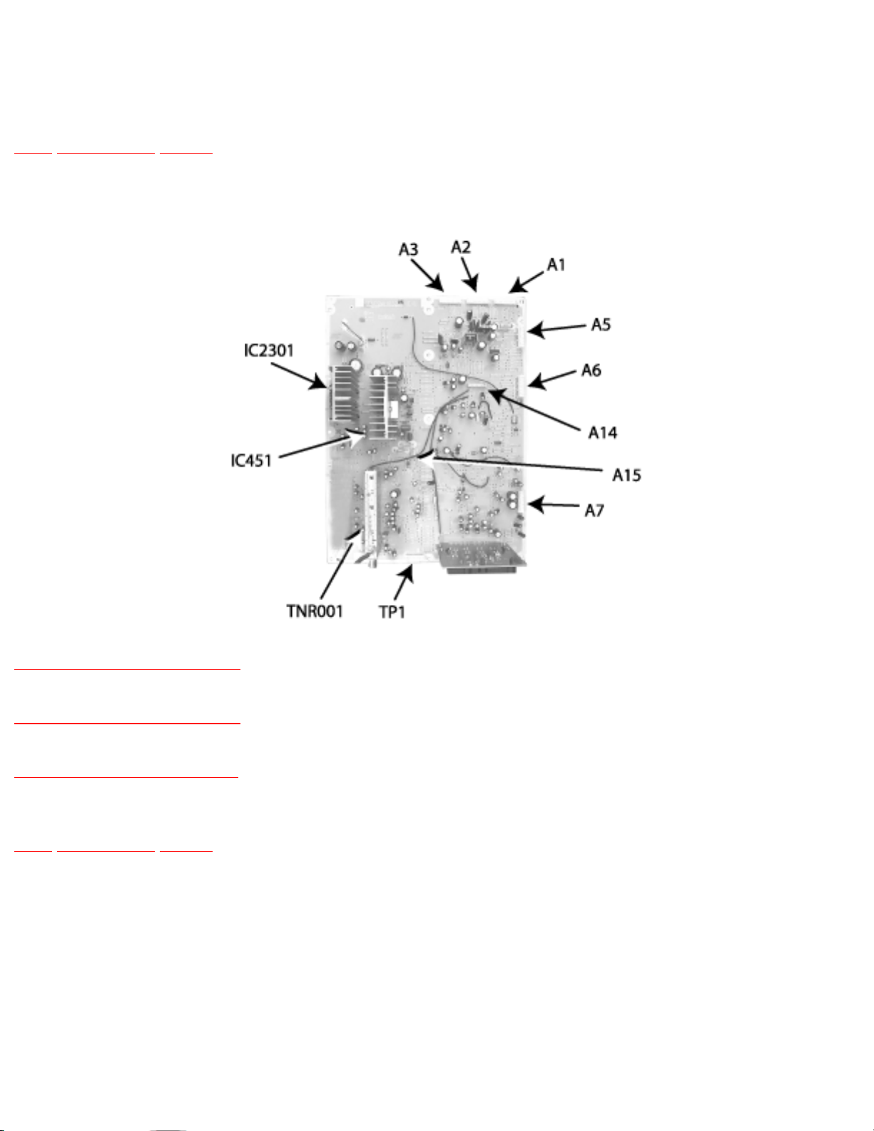
15.1 A-Board components
TOP PREVIOUS NEXT
A-Board components
15.1.1 D-Board components
15.1.2 G-Board components
15.1.3 L-Board components
TOP PREVIOUS NEXT
http://tsn.pstc.panasonic.com/viewing/NA/CT-36SL13G/SVC/s1501000000.html05.12.2008 0:03:52
Page 85
http://tsn.pstc.panasonic.com/viewing/NA/CT-36SL13G/SVC/s1501010000.html
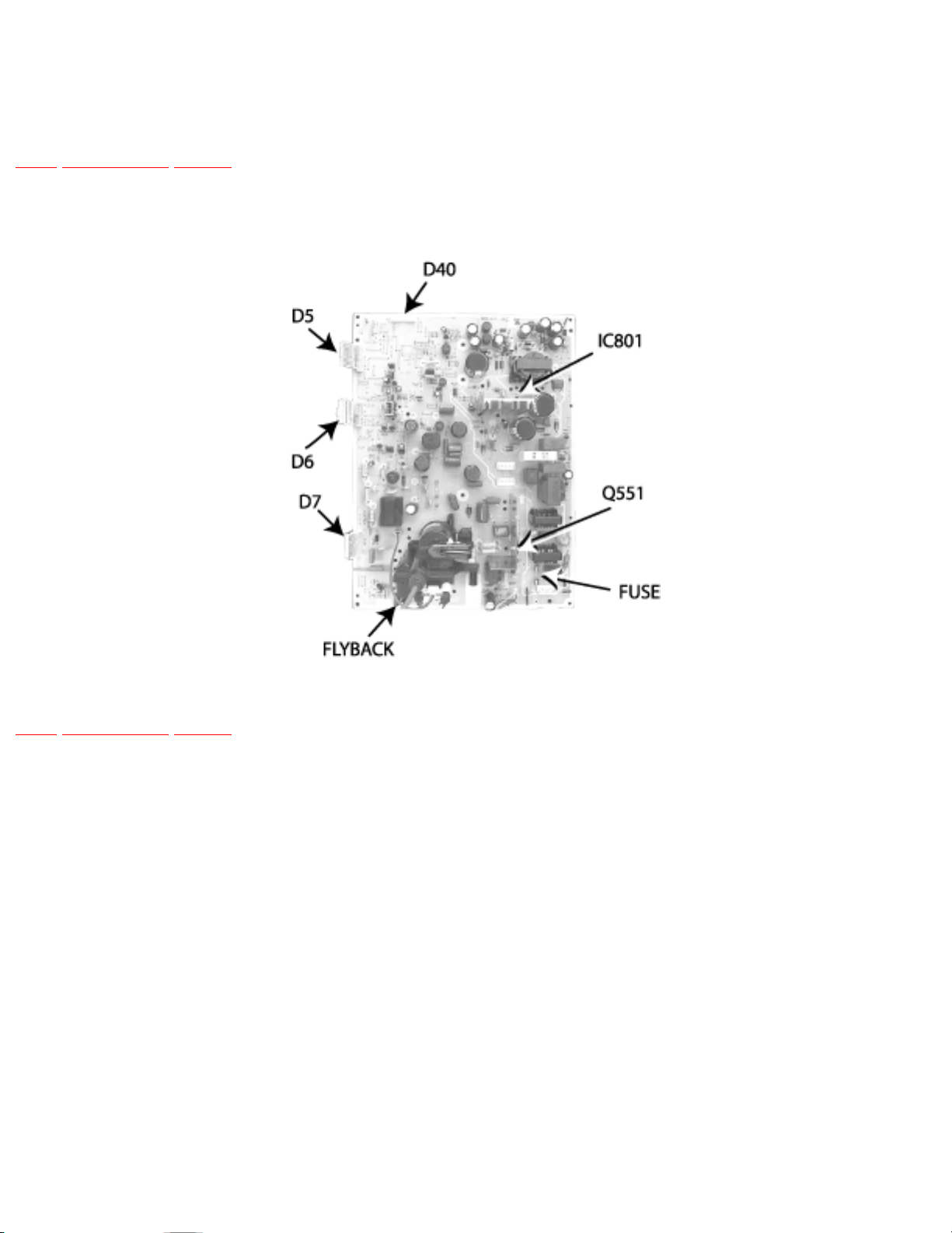
15.1.1 D-Board components
TOP PREVIOUS NEXT
D-Board components
TOP PREVIOUS NEXT
http://tsn.pstc.panasonic.com/viewing/NA/CT-36SL13G/SVC/s1501010000.html05.12.2008 0:03:57
Page 86
http://tsn.pstc.panasonic.com/viewing/NA/CT-36SL13G/SVC/s1501020000.html
15.1.2 G-Board components
TOP PREVIOUS NEXT
G-Board components
TOP PREVIOUS NEXT
http://tsn.pstc.panasonic.com/viewing/NA/CT-36SL13G/SVC/s1501020000.html05.12.2008 0:04:01
Page 87
http://tsn.pstc.panasonic.com/viewing/NA/CT-36SL13G/SVC/s1501030000.html
15.1.3 L-Board components
TOP PREVIOUS NEXT
L-Board components
TOP PREVIOUS NEXT
http://tsn.pstc.panasonic.com/viewing/NA/CT-36SL13G/SVC/s1501030000.html05.12.2008 0:04:05
Page 88
http://tsn.pstc.panasonic.com/viewing/NA/CT-36SL13G/SVC/s1600000000x.html
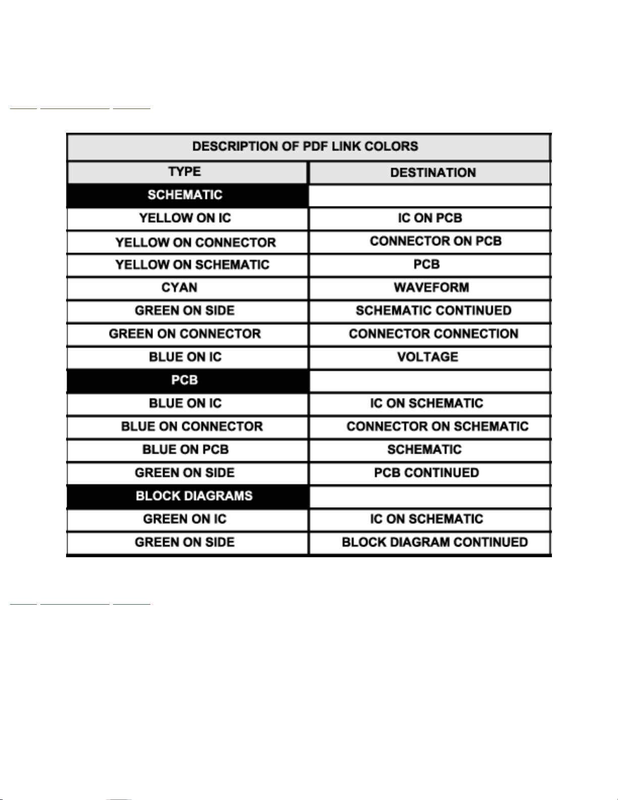
16 Reference for PDF colors
TOP PREVIOUS NEXT
TOP PREVIOUS NEXT
http://tsn.pstc.panasonic.com/viewing/NA/CT-36SL13G/SVC/s1600000000x.html05.12.2008 0:04:18
Page 89

http://tsn.pstc.panasonic.com/viewing/NA/CT-36SL13G/SVC/s1700000000x.html
17 Conductor views
TOP PREVIOUS NEXT
17.1 A-Board printed circuit 1 of 2
17.2 A-Board printed circuit 2 of 2
17.3 D-Board printed circuit 1 of 2
17.4 D-Board printed circuit 2 of 2
17.5 G-Board (SC models) printed circuit 1 of 2
17.6 G-Board (SC models) printed circuit 2 of 2
17.7 G-Board (SL models) printed circuit 1 of 2
17.8 G-Board (SL models) printed circuit 2 of 2
17.9 L-Board printed circuit
17.10 K-Board printed circuit
TOP PREVIOUS NEXT
http://tsn.pstc.panasonic.com/viewing/NA/CT-36SL13G/SVC/s1700000000x.html05.12.2008 0:04:24
Page 90

http://tsn.pstc.panasonic.com/viewing/NA/CT-36SL13G/SVC/s1701000000.html
17.1 A-Board printed circuit 1 of 2
TOP PREVIOUS NEXT
TOP PREVIOUS NEXT
http://tsn.pstc.panasonic.com/viewing/NA/CT-36SL13G/SVC/s1701000000.html05.12.2008 0:04:27
Page 91
J
I
H
G
F
E
D
C
B
A
1 234 56 7 8
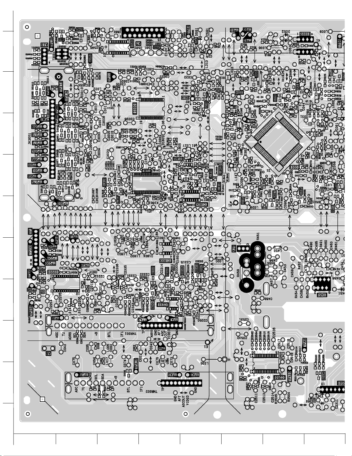
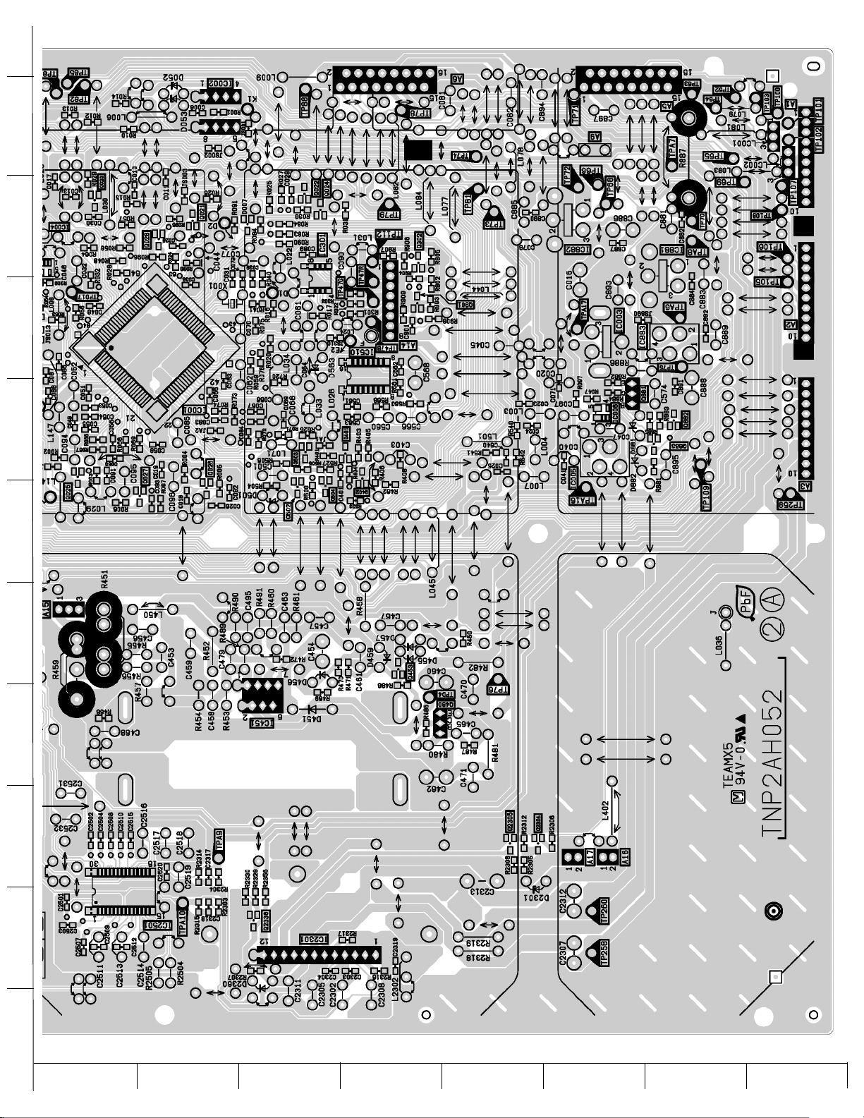
A-BOARD 1 OF 2 TNP2AH052 CT-36SL13G, CT-32SL13G, CT-36SC13G, CT-32SC13G, CT-3653G
Page 92

http://tsn.pstc.panasonic.com/viewing/NA/CT-36SL13G/SVC/s1702000000.html
17.2 A-Board printed circuit 2 of 2
TOP PREVIOUS NEXT
TOP PREVIOUS NEXT
http://tsn.pstc.panasonic.com/viewing/NA/CT-36SL13G/SVC/s1702000000.html05.12.2008 0:04:38
Page 93
J
I
H
G
F
E
D
C
B
A
1 234 56 7 8
A-BOARD 2 OF 2 TNP2AH052 CT-36SL13G, CT-32SL13G, CT-36SC13G, CT-32SC13G, CT-3653G
Page 94

http://tsn.pstc.panasonic.com/viewing/NA/CT-36SL13G/SVC/s1703000000.html
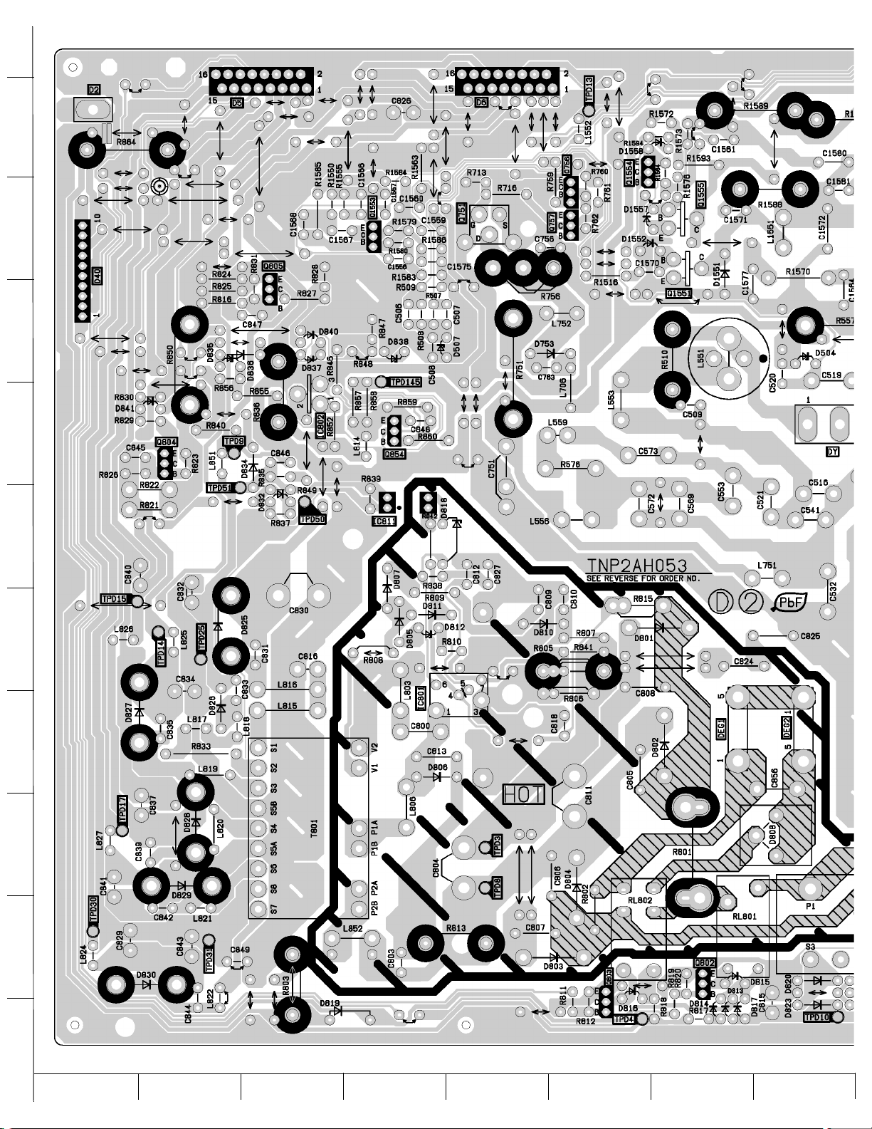
17.3 D-Board printed circuit 1 of 2
TOP PREVIOUS NEXT
TOP PREVIOUS NEXT
http://tsn.pstc.panasonic.com/viewing/NA/CT-36SL13G/SVC/s1703000000.html05.12.2008 0:04:50
Page 95
J
I
H
G
F
E
D
C
B
A
1 234 56 7 8
D-BOARD 1 OF 2 TNP2AH053 CT-36SL13G, CT-32SL13G, CT-36SC13G, CT-32SC13G, CT-3653G
Page 96

http://tsn.pstc.panasonic.com/viewing/NA/CT-36SL13G/SVC/s1704000000.html
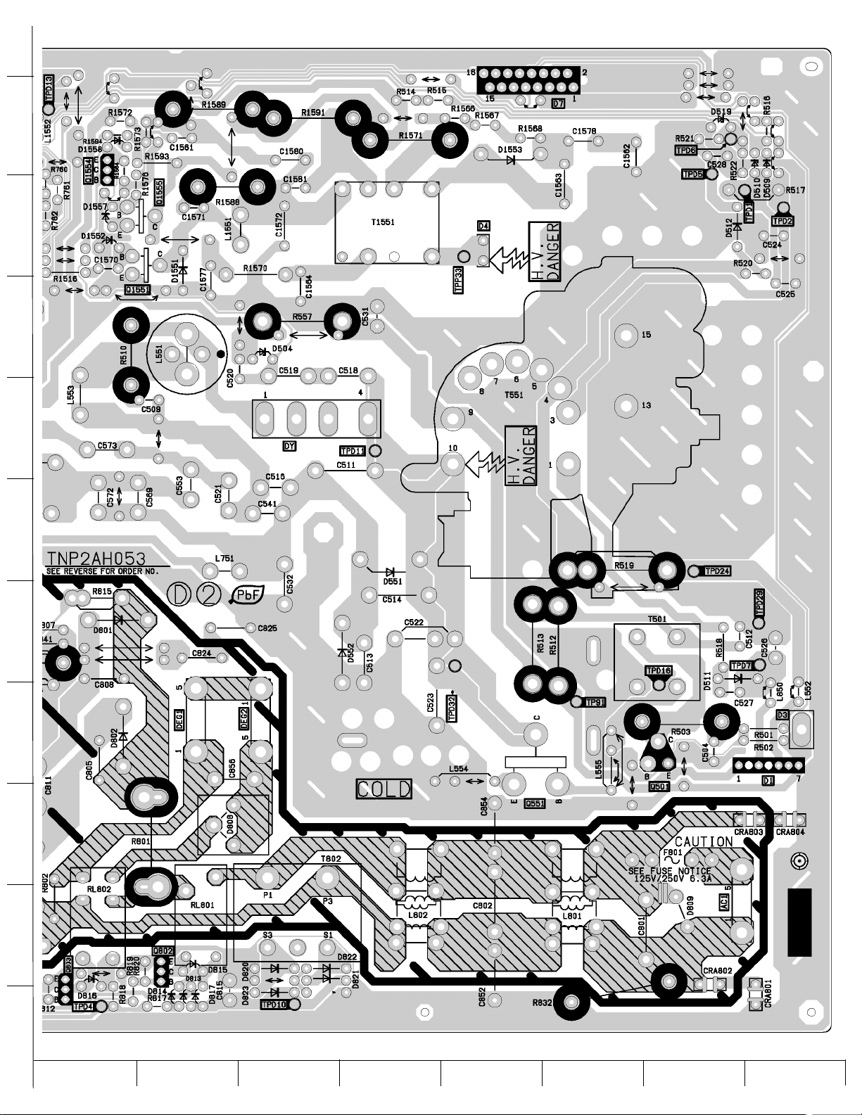
17.4 D-Board printed circuit 2 of 2
TOP PREVIOUS NEXT
TOP PREVIOUS NEXT
http://tsn.pstc.panasonic.com/viewing/NA/CT-36SL13G/SVC/s1704000000.html05.12.2008 0:05:00
Page 97
J
I
H
G
F
E
D
C
B
A
1 234 56 7 8
D-BOARD 2 OF 2 TNP2AH053 CT-36SL13G, CT-32SL13G, CT-36SC13G, CT-32SC13G, CT-3653G
Page 98

http://tsn.pstc.panasonic.com/viewing/NA/CT-36SL13G/SVC/s1705000000.html
17.5 G-Board (SC models) printed circuit 1 of 2
TOP PREVIOUS NEXT
TOP PREVIOUS NEXT
http://tsn.pstc.panasonic.com/viewing/NA/CT-36SL13G/SVC/s1705000000.html05.12.2008 0:05:09
Page 99
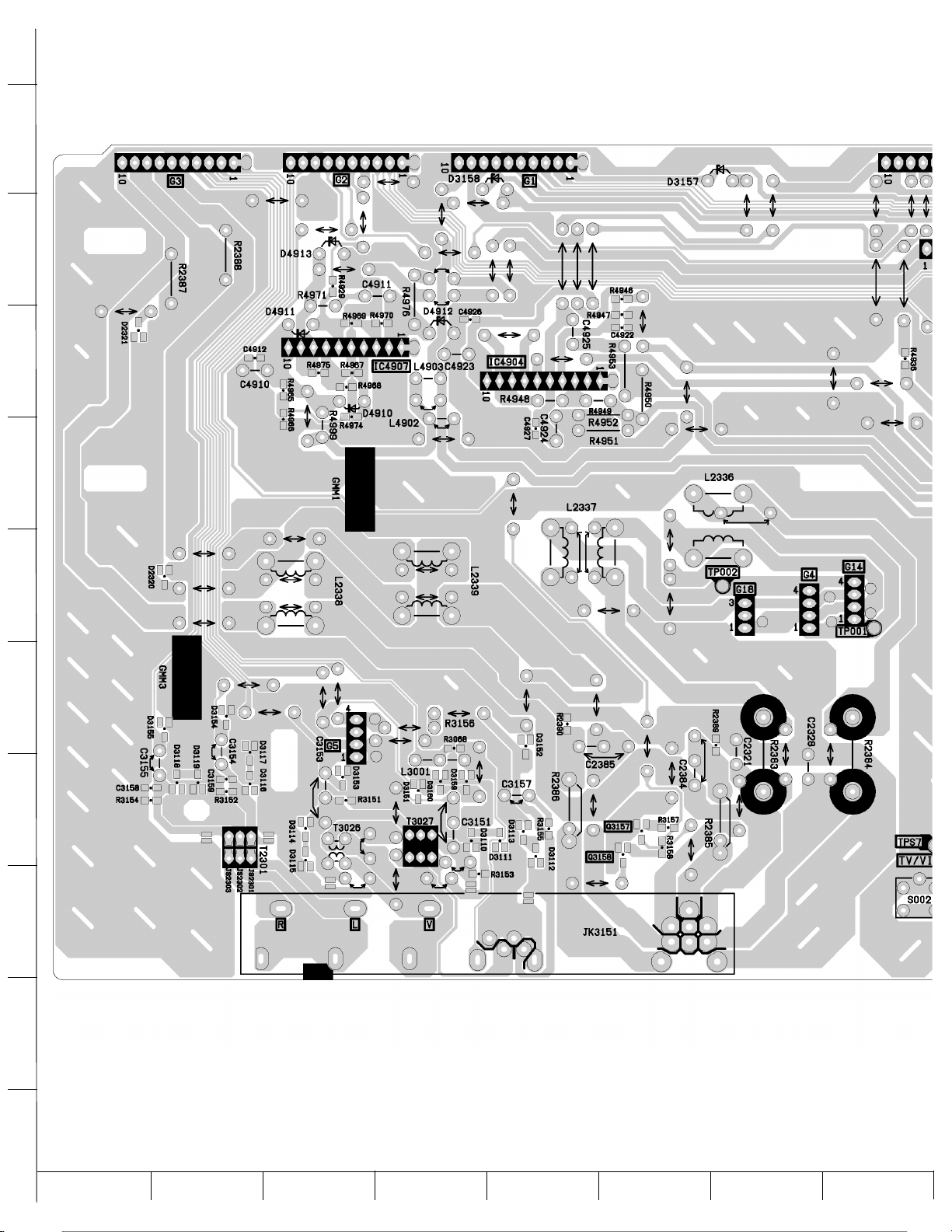
J
I
H
G
F
E
D
C
B
A
1 234 56 7 8
G-BOARD 1 OF 2 TNP2AA141 CT-36SC13G, CT-32SC13G, CT-3653G
Page 100

http://tsn.pstc.panasonic.com/viewing/NA/CT-36SL13G/SVC/s1706000000.html
17.6 G-Board (SC models) printed circuit 2 of 2
TOP PREVIOUS NEXT
TOP PREVIOUS NEXT
http://tsn.pstc.panasonic.com/viewing/NA/CT-36SL13G/SVC/s1706000000.html05.12.2008 0:05:16
 Loading...