

Panasonic CT-31SF20R Owner’s Manual
Panasonico
Color Television
Printed in U.S.A.
Operating Instructions
Read these instructions completely before operating this set.
Contents subject to change without notice or obligation.
TQB2A0726
Safety Instructions
CAUTION
i
CAUTION: To reducethe risk of electricshock do n_otremove cover or back. No
user-serviceable parts Inside. Refer servicing to qualified service personnel.
The lightning flash with ar- The exclamation pointwithin
A row-head within a triangle _ a triangle is intended to tell
that parts insidethe product ating and servtcing instruc-
are a riskof electricshockto tions are in the papers with
is intended to tell the user A the userthat importantoper-
persons, the appliance.
Note To CATV System Installer: This reminder is provided to call the CATV system installer's attention to Article
820-40 ofthe NEC that provides guidelines for proper grounding and, in particular, specifies that the cable ground shall be
connected to the grounding system of the building, as close to the point of cable entry as practical.
Safety Instructions For Television Receivers
1. Read and apply the operating instructionsprovided with your television receiver.
2. Read all of the instructionsgiven here and retainthem for later use.
3. Unplug this television receiver from the wall outlet before cleaning. Do not use liquidor aerosol cleaners. Use a damp
clothfor cleaning.
4. Do not use attachments not recommended by the television receiver manufacturer as they may cause hazards.
5. Do not use this television receiver near water. For example: Avoid placing itnear a bathtub, washbowl, kitchen sink, or
laundry tub, in a wet basement, or near a swimming poo!, etc.
6. DOnot place thistelevision receiver on an unstable cart, stand, ortable. The television receiver mayfall, causing serious
injury to a child or adult, and serious damage to the appliance. Use only with a cart or stand recommended by the
manufacturer, or soldwith the television receiver. Wall or shelf mounting should follow the manufacturer's instructions,
and should use a mounting kit approved by the manufacturer.
6A. An appliance and cart combination should be moved with care. Quick stops, excessive force, and
uneven surfaces may cause the appliance and cart combination to overturn.
7. Slots and openings in the cabinet and the back or bottom are provided for ventilation, and to insure
reliable operation of the television receiver and to protect it from overheating. These openings must not be blocked or
covered. The openings should never be blocked by placing the television receiver on a bed, sofa, rug, or other similar
surface. This television receiver should never be placed near or over a radiator or heat register. This television receiver
should not be placed in a built-in installation such as a bookcase unless proper ventilation is provided.
8. Operate only from the type of power source indicated on the marking label. If you are not sure of the type of power
supplied to your home consult your television dealer or local power company. For television receivers designed to
operate from battery power, refer to the operating instructions.
9. Thistelevision receiver isequipped with a polarized a!ternating-current lineplug (a plug having one blade wider than the
other). This plugwill fit into the power outlet only one way. This isa safety feature. Ifyou are unable to insertthe plug
fully into the outlet, try reversing the plug_If.
the plug should still fail to fit, contact your
electricianto replace your obsolete outlet. Do
not defeat the safety purpose ofthe polarized
plug.
10.
DO not allow anything to rest on the power
cord. Do not locate this television receiver
where the cord will be abused by persons
walking on it.
11.
Follow allwarnings and instructidnsmarked
on the television receiver.
12.
Do not overload wall outlets and extension
cords as this can result in fire or electric
shock.
3.
Never push objects of any kind into this
television receiver through cabinet slots as
they may touch dangerous voltage points or
short out parts that could result in a fire or
electric shock. Never spill liquid of any kind
on the television receiver.
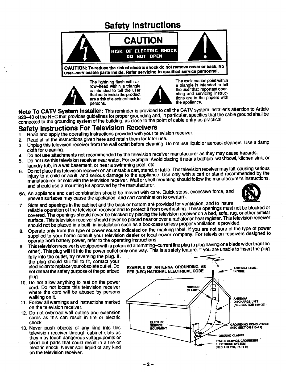
EXAMPLE OF ANTENNA GROUNDING AS _
PER (NEC)NATIONAL ELECTRICAL CODE __ ._h._,_ LEAD-
I semnce _ _ I I'_1 /_'/_ GROUNOING CONDUCTORS
.J+'-._l-""--'- ELECTROOE SYSTEM
POWER SEmnCE GROUNDING
(NEC ART 250, PART H)
-2-
1.4.Ifanoutsideantennaisconnectedtothetelevisionequipment,besuretheantennasystemisgroundedsoastoprovide
someprotectionagainstvoltagesurges and builtupstaticcharges. Inthe U.S. Section 810 of the National ElectricalCode
and inCanada Part I of the Canadian Electrical Code provides informationwith respect to proper grounding of the mast
and supporting structure, grounding of the lead-in wire to an antenna discharge unit, size of grounding conductors,
locationof antenna-discharge unit, connection to grounding electrodes, and requirements for the grounding electrode.
See Figure.
15. For added protectionfor this television receiver during a lightning storm, or when it isleft unattended and unused for long
periodsoftime, unplugit from the wall outlet and disconnect the antenna. This will prevent damage tothe receiver due to
lightning and power-line surges.
16. An outside antenna system should not be located inthe vicinity of overhead power linesor other electric lightor power
circuits,or where it can fall into such power lines or circuits. When installing an outside antenna system extreme care
should be taken to keep from touching such power lines or circuits as contact with them might be fatal.
17. Unplugthistelevision receiver from the wall outlet, and refer servicingto qualified service personnel under the following
conditions:
a. When the power cord or plug is damaged or frayed.
b. If liquid has been spilled intothe television receiver.
c. Ifthe television receiver has been exposed to rain or water.
d. Ifthe television receiver does not operate normally byfollowingthe operating instructions.Adjust only those controls
that are covered by the operating instructionsas improper adjustment of other controls may result indamage and will
often require extensive work by a qualified technician to restore the television receiver to normal operation.
e. Ifthe television receiver has been dropped or the cabinet has been damaged.
f. When the television receiver exhibits a distinct change in performance - this indicates a need for service.
18. Do not attempt to service this television receiver yourself as opening or removing covers may expose you to dangerous
voltage or other hazards. Refer all servicing to qualified service personnel.
19. When replacement parts are required, be sure the service technician has used replacement parts specified by the
manufacturer that have the same characteristics as the originalpart. Unauthorized substitutions may result infire, electric
shock, or other hazards.
20. Upon completion ofany service or repairs to this television receiver, ask the servicetechnician to perform routine Safety
checks to determine that the television isin safe operating condition.
21. WARNING: To prevent fire or shock hazard, do not expose this appliance to rain or moisture.
22. CAUTION: TO PREVENT ELECTRIC SHOCK DO NOT USE THIS (POLARIZED) PLUG WITH AN EXTENSION CORD,
RECEPTACLE OR OTHER OUTLET UNLESS THE BLADES CAN BE FULLY INSERTED TO PREVENT BLADE
EXPOSURE.
•NOTE: This equipment isdesigned to operate inthe U.S.A., Canada and other countries where the broadcasting system and
AC house current is exactly the same as inthe U.S.A. and Canada.
Important Information Regarding Use of Video Games, Computers, Teletext or Other Fixed Image Displays.
The extended use of fixed image program material can cause a permanent "shadow image" on the picture tube. This
background image isviewable onnormal programs intheform of astationaryfixed image. This type of irreversiblepicturetube
deterioration can be limited by observing the followingsteps:
A. Reduce the brightness/contrast setting to a minimum viewing level.
B. Do notdisplay the fixed image for extended periods of time.
C,. Turn the power off when not in actual use.
NOTE: The marking or reta!ned image on the picture tube resulting from fixed image use is not an operating defect and as
such is notcovered byWarranty. This productisnotdesigned todisplay fixed image patterns for extended periods of
time.
Specifications
Power Source:
Channel Capability:
Video Input Jack (3):
Audio Input Jack (3):
To Audio AMP Jacks:
S-VHS Input Jacks (2):
Stereo Sound:
Dome Speaker System:
Program Out:
Program Out:
Picture In Picture:
CiosedCaption Display:
Specifications are subject to change without notice or obligation.
120V 60Hz, AC . .
181 channels(See chart)
VHF 2~13, UHF 14~69, Cable 125 channels
1V p-p, 75 ohm, phonojacktype
Highimpedance- .10K.(-2,.500mVrms
0~4.0V rms 10K
S-_Video(Y-C) Connector
Video2V p--p75 ohmphonojacktype
Audio500mV rms 10K.Qphonojacktype
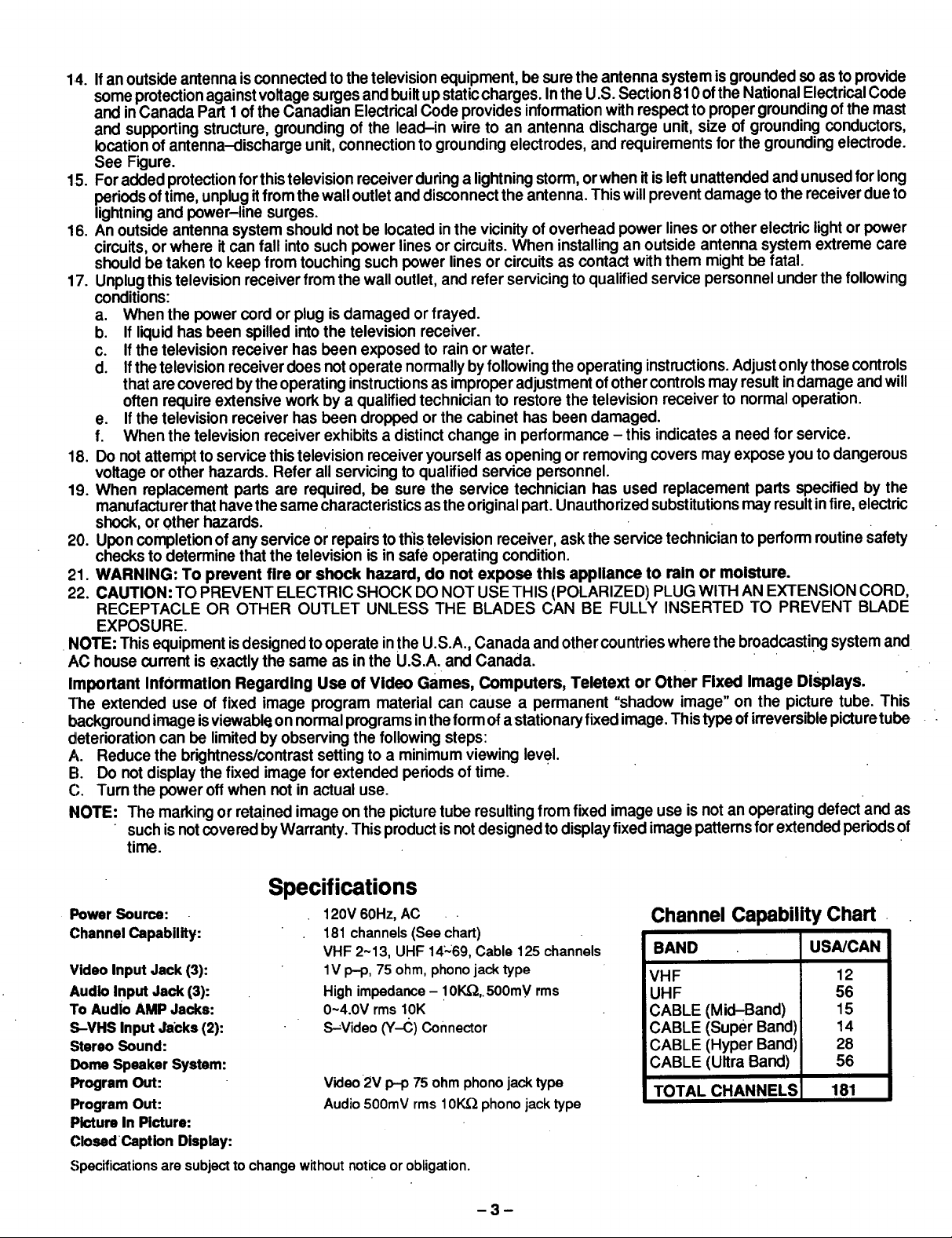
Channel Capability Chart
BAND USA/CAN
VHF 12
UHF 56
CABLE (Mid-Band) 15
CABLE (Super Band) 14
CABLE (Hyper Band) 28
CABLE (Ultra Band) 56
TOTAL CHANNELS 181
3
Introduction
Congratulations on Your New Purchase
Your new video component features an all solid state chassiswhich isdesigned to give you many years of enjoyment. It
was thoroughly tested and adjusted at the factory for best performance.
In order for you to take fulladvantage of your new video component, please read and follow the installationand operating
instructionssupplied with this product.
Customer's Record
The modeland sedalnumber of thisproductmay be found on its back cover. You shouldnote the modeland serial number
in the space provided and retainthis book as a permanent record of your purchase to aid in identification inthe event of
theft or loss.
Model Number: Serial Number:
Table of Contents
Safety Instructions .......................... 2
Specifications .............................. 3
Introduction ............................... 4
Installation ................................ 5
Receiver Location .......................... 5
Optional External Equipment Connections ....... 5
AC Power Supply Cord ...................... 5
Battery Installation .......................... 5
Antenna/Cable Connections .................. 6
PIP Antenna Connection . .................... 7
Cable Converter Box Connection .............. 7
Location of Controls (Receiver) ............... 8
Quick Reference Control Operation (Receiver) .... 9
Location of Controls (Remote Control) ........ 10
Quick Reference Control Operation (Remote) ... 10
Control Operation ......................... 12
Power Button. ....... ...................... 12
Volume (Vol) Buttons ....................... 12
Mute Button .............................. 12
Channel Change Features ............... ... 12
Channel (Ch) Buttons ............ .. ...... 12
Keyboard "0through 9" & 100 Buttons ....... 12
W/Video Button ..... ; .................... 13
Recall Button ............................. 13
Sleep Button ............................. 13
R-Tune (Rapid Tune) Button................. : 13
Skip Button ........................ ...... 13
Fav Ch (Favorite Channel) Button ............. 14
VCR Function Buttons ..................... 14
Cable TV Buttons ......................... 14
ANT (Antenna) Button ...................... 14
Multi Button .............................. 15
Closed Caption Button ...................... 16
Main Menu (Icons) ........... .............. 17
Picture Adjustments ........................ 18
Color . ................................ : 18
Tint ................................... 18
Brightness ............................. 18
Picture ................................ 18
Sharpness ............ : ................. 18
Favorite (Picture) ........................ 19
Picture Settings ........................... 20
Favorite Picture Adjustments ................ 20
Video NR (Noise Reduction) ................ 21
Auto Color .............................. 21
Audio Adjustments .......................... 22
Bass, Treble & Balance Adjustments ......... 22
Surround ............................... 23
Surround Mode Stereo Enhancement ......... 23
Audio Mode Selection (Stereo/SAP/Mono) .... 23
(Dual Program) Timer ........................ 24
(Program) Timer ........ . .. .............. 24
PIP Channel Scan ........................ 26
PIP Video Adjustments .................... 26
Favorite Channel Programming .............. 27
Channel Caption ......................... 28
Channel Lockout ......... ; ............... 29
Set-Up Features ........................... 30
Set Time (Clock) . ....... . .... . ...... ..... 30
•Set Day ................... . ............ 31
W/ANT-Cable Tuning Mode ............... 31
Auto Programming 31
Manual Programming ................... .. 32
Displays "Stereo-SAP-Mono". .............. 33
Caption Field ............................ 33
[TV] Speaker ............................ 33
PIP (Picture in Picture) Button ................. 34
PIP Frame Size Button ...................... 34
PIP Freeze Button ........................... 35
PIP Picture Swap Button 35
PIP Audio Swap Button ...................... 35
PIP Search Button .......................... 35
PIP Frame Locator Buttons ................... 35
Programming the Universal Remote Control .... 36
Infra-Red Remote Control Codes .............. 39
Optional Equipment Connection & Operation ... 40
Stereo Connection (ToAudio AMP). ........ ... 40
PROG (Program) Out Connection .............. 40
Video/Audio Connection ............. '........ 41
S-Video Connection ........................ 41
Care & Cleaning .... ........................... 42
TroubleshooUng Chart. ..................... 43
Power Loss ............................... 43
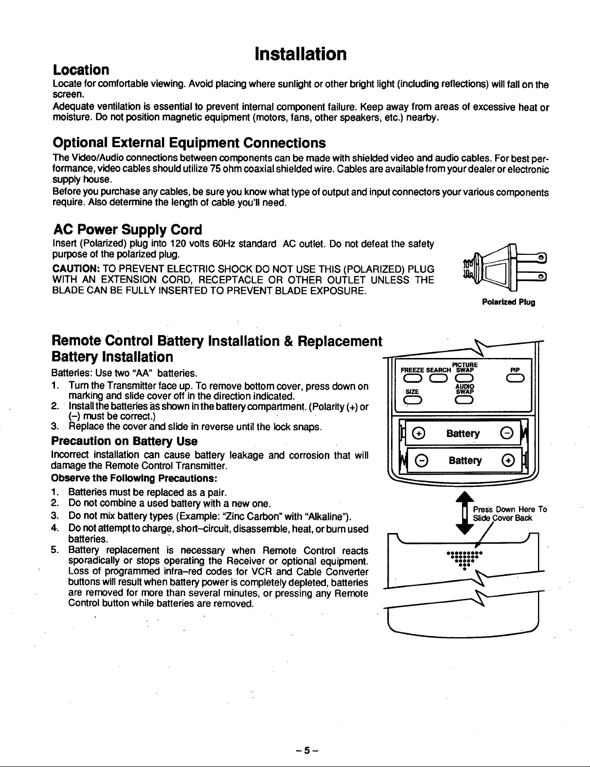
Installation
Location
Locate for comfortable viewing. Avoid placing where sunlight or other brightlight (including reflections) willfall onthe
screen.
Adequate ventilation is essential to prevent internal component failure. Keep away from areas of excessive heat or
moisture. Do notposition magnetic equipment (motors, fans, other speakers, etc.) nearby.
Optional External Equipment Connections
The Video/Audio connections between components can be made with shielded video and audio cables. For bestper-
formance, video cables shouldutilize 75 ohm coaxial shielded wire. Cables are available from yourdealer orelectronic
supply house.
Before you purchase any cables, be sure you know what type of output and inputconnectors your various components
require. Also determine the length of cable you'll need.
AC Power Supply Cord
Insert (Polarized) plug into 120 volts 60Hz standard AC outlet. Do not defeat the safety
purpose of the polarized plug.
CAUTION: TO PREVENT ELECTRIC SHOCK DO NOT USE THIS (POLARIZED) PLUG
WITH AN EXTENSION CORD, RECEPTACLE OR OTHER OUTLET UNLESS THE
BLADE CAN BE FULLY INSERTED TO PREVENT BLADE EXPOSURE.
Polarized Plug
Remote Control Battery Installation & Replacement _ -
Battery Installation " .c,..E
Batteries: Use two "AA" batteries.
1. Turn the Transmitter face up. To remove bottom cover, press down on
marking and slide cover off in the direction indicated.
2. Install the batteries a.Sshown in the battery compartment. (Polarity (+) or
(-) must be correct.)
3. Replace the cover and slide in reverse until the lock snaps.
Precaution on Battery Use
Incorrect installation can cause battery leakage and corrosion that will
damage the Remote Control Transmitter.
Observe the Following Precautions:
1. Batteries must be replaced as a pair.
2. Do not combine a used battery with a new one.
3. Do not mix battery types (Example: "Zinc Carbon" with "Alkaline").
4. Do not attemptto charge, short-circuit, disassemble, heat, orburn used
batteries.
5. Battery replacement is necessary when Remote Control reacts
sporadically or stops operating the Receiver or optional equipment.
Loss of programmed infra-red codes for VCR and Cable Converter
buttons willresult when battery power is completely depleted, batteries
are removed for more than several minutes, or pressing any Remote
Control button while batteries are removed.
FREEZE SEARCH SWAP PIP
(Z)C=)0 0
SIZE SWAP
AUmO
!2D CD
PressDOwnHereTo
ideCoverBack
-5-
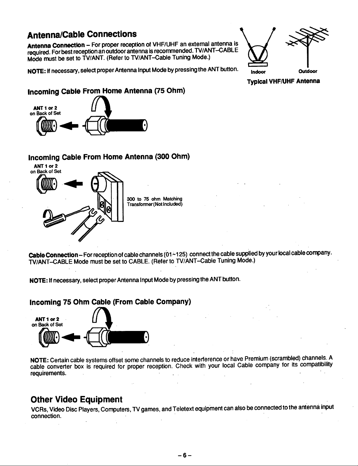
Antenna Connection - For proper reception of VHF/UHF an external antenna is
required. Forbest receptionan outdoor antenna is recommended. TV/ANT--CABLE
Antenna/Cable Connections _
Mode must be set to TV/ANT. (Refer to TV/ANT-Cable Tuning Mode.)
NOTE: If necessary, select properAntenna InputMode bypressingthe ANT button, tndoor Outdoor
Typical VHF/UHF Antenna
Incoming Cable From Home Antenna (75 Ohm)
ANTlor 2
on Backof Set
Incoming Cable From Home Antenna (300 Ohm)
ANT 1 or 2
on Back of Set
300 to 75 ohm Matching
Transformer(Not Included)
Cable ConnecUon- For reception ofcable channels (01"_125) connect thecable supplied by yourlocalcable company.
TV/ANT--CABLE Mode must be set to CABLE. (Refer to IV/ANT-Cable Tuning Mode.)
NOTE: Ifnecessary, select properAntenna Input Mode by pressingthe ANT button.
Incoming 75 Ohm Cable (From Cable Company)
ANTlor 2
on Backof Set
NOTE: Certain cable systems offset some channels to reduce interference or have Premium (scrambled) channels. A
cable converter box is required for proper reception. Check with your local Cable company for its compatibility
requirements. .
Other Video Equipment
VCRs, Video Disc Players, Computers, TV games, and Teletext equipment can also be connected to the antenna input
connection.
-6-
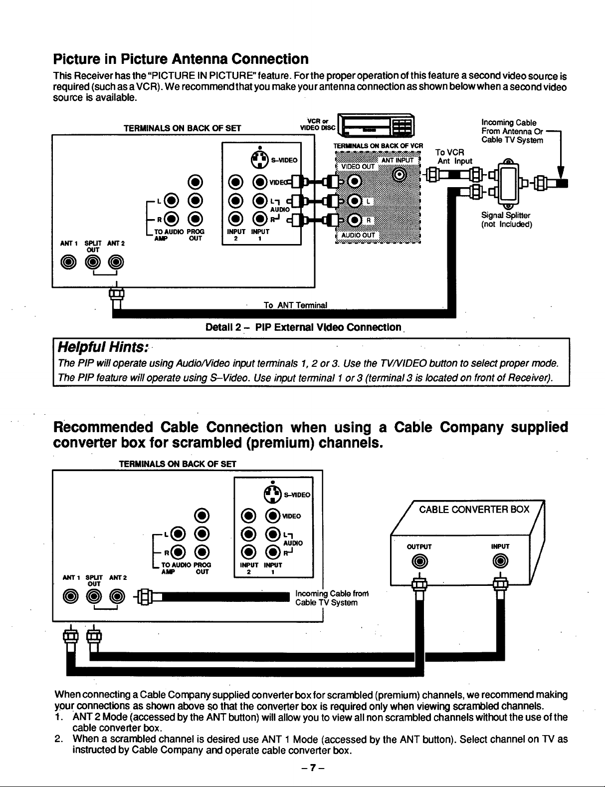
Picture in Picture Antenna Connection
This Receiver hasthe "PICTURE IN PICTURE" feature. Forthe proper operation ofthis feature a second video source is
required (such as a VCR). We recommend that you make your antenna connection as shown below when a second video
source is available.
TERMINALS ON BACK OF SET
®
®
VCR or
VIDEO DISC
TERMINALS ON BACK OF VCR
ANTiNPUT Ant Input
To VCR
IncomingCable
FromAntennaOr
CableTV System
®®
®®
ANTI SPUT ANT2
OUT
AMP OUT
000
Helpful Hints:..
The PIP will operate usin0 Audio/Video input terminals 1, 2 or 3. Use the TVA/IDEO button to select proper mode.
The PIP feature will operate using S-Video. Use input terminal I or 3 (terminal 3 is located on front of Receiver).
INPUT INPUT
2 1
To ANT Terminal
I
Detail 2 - PIP External Vldeo Connection.
SignalSplitter
(not Included)
Recommended Cable Connection when using a Cable
Company supplied
converter box for scrambled (premium) channels.
TERMINALS ON BACK OF SET
) S-VIDEO ;
®
ANT1 SPLIT ANT2
OUT
O O _) _ Incoming Cablefrorrt
AMP OUT
® ® o0o
iNPUT INPUT
2 1
CableTV System
CABLE CONVERTER BOX(//]
OUTPUTo I_ [/
' ' I
When connecting a Cable Company supplied converter box for scrambled (premium) channels, we recommend making
your connections as shown above Sothat the converter box is required only when viewing scrambled channels.
1. ANT 2 Mode (accessed bythe ANT button) will allow you to view all non scrambled channels withoutthe use ofthe
cable converter box.
2. When a scrambled channel is desired use ANT 1 Mode (accessed by the ANT button). Select channel on TV as
instructed by Cable Company and operate cable converter box.
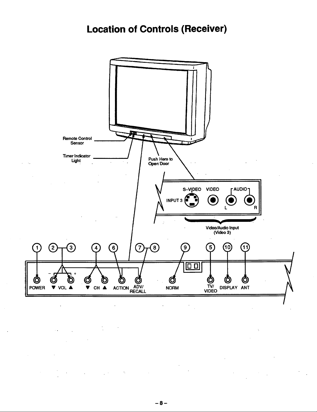
Location of Controls (Receiver)
RemoteControl
Sensor
,)
]l
POWER
TimerIndicator
Light
• VOL • • CH • ACTIONREADVI//L
PushHereto
Open'Door
,NPOT3_®L 0
NORM TV/ DISPLAY ANT
Video/AudioInput
(Video3)
VIDEO
-8-
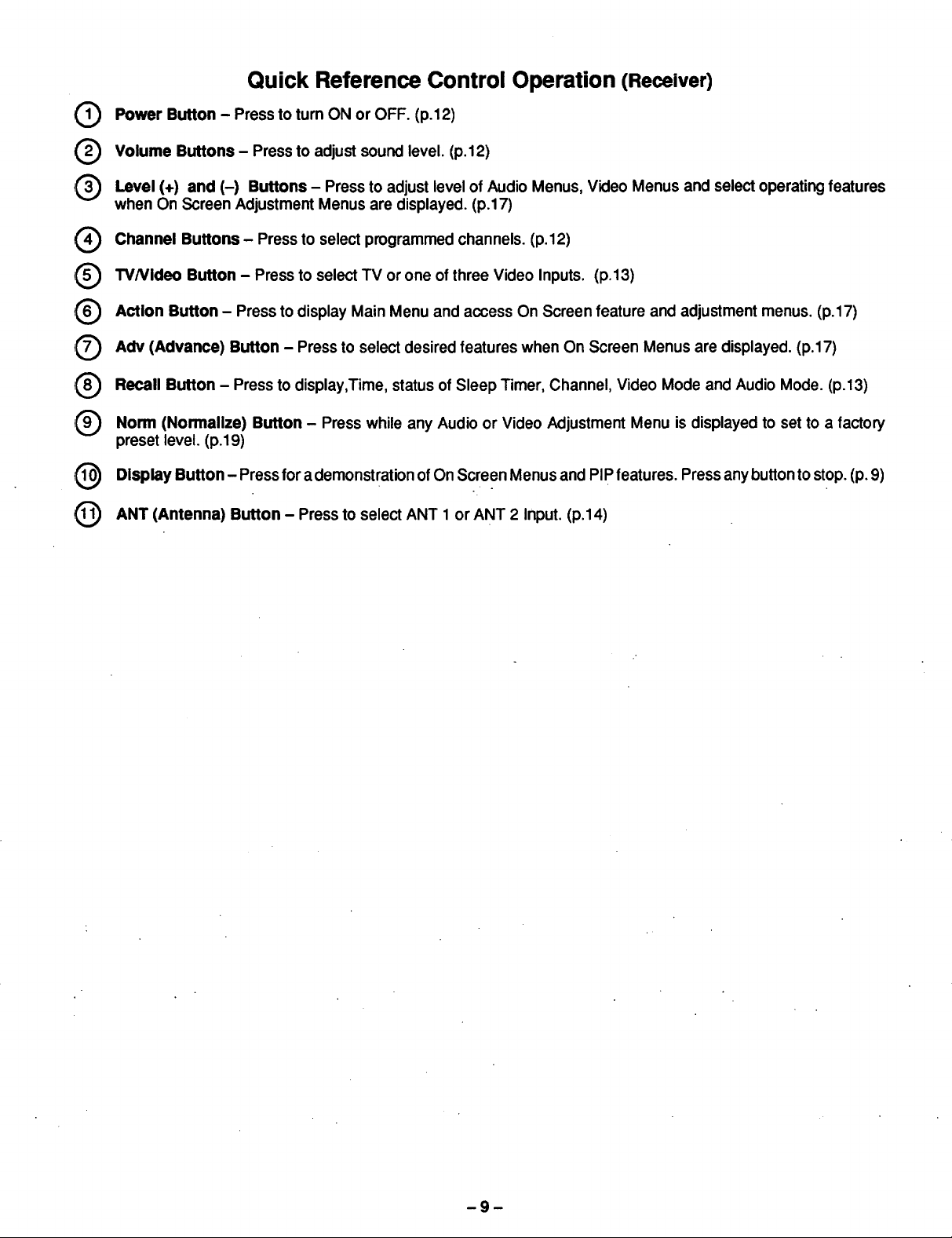
Quick Reference Control Operation (Receiver)
Power Button - Press to turn ON or OFF. (p.12)
@
Volume Buttons - Press to adjust sound level. (p.12)
®
Level (+) and (-) Buttons - Press to adjust level of Audio Menus, Video Menus and select operating features
®
when On Screen Adjustment Menus are displayed. (p.17)
Channel Buttons- Press to select programmed channels. (p.12)
®
TVNIdeo Button - Press to select TV or one of three Video Inputs. (p.13)
®
Action Button- Press to display Main Menu and access On Screen feature and adjustment menus. (p.17)
®
Adv (Advance) Button - Press to select desired features when On Screen Menus are displayed. (p.17)
@
Recall Button - Press to display,Time, status of Sleep Timer, Channel, Video Mode and Audio Mode. (p.13)
®
Norm (Normalize) Button - Press while any Audio or Video Adjustment Menu is displayed to set to a factory
,®
preset level. (p.19)
Display Button - Press for a demonstration ofOn Screen Menus and PIP features. Press any buttontostop. (p. 9)
®
ANT (Antenna) Button - Press to select ANT 1 or ANT 2 Input. (p.14)
@
-9-

Location of Controls (RemoteControl)
@
@
@
R-TUNE SKIP
VOLUME FAV CH CHANNEL
®®®®®
®®®®
C_))-
STOP PLAY FF
CH OREC IPAUSE F.ADVIIII
®
®
@
Quick Reference Control Operation (Remote Control)
Power Button - Press to turn ON or OFF. (p.l 2)
Volume Buttons- Press to adjust sound level. (p.12)
Level (+) and (-) Buttons - Press to adjust level of Audio Menus,Video Menus and Select operating features
when On Screen Adjustment Menus are displayed. (p.17)
Channel Buttons - Press to select programmed channels. (p.12)
-10-
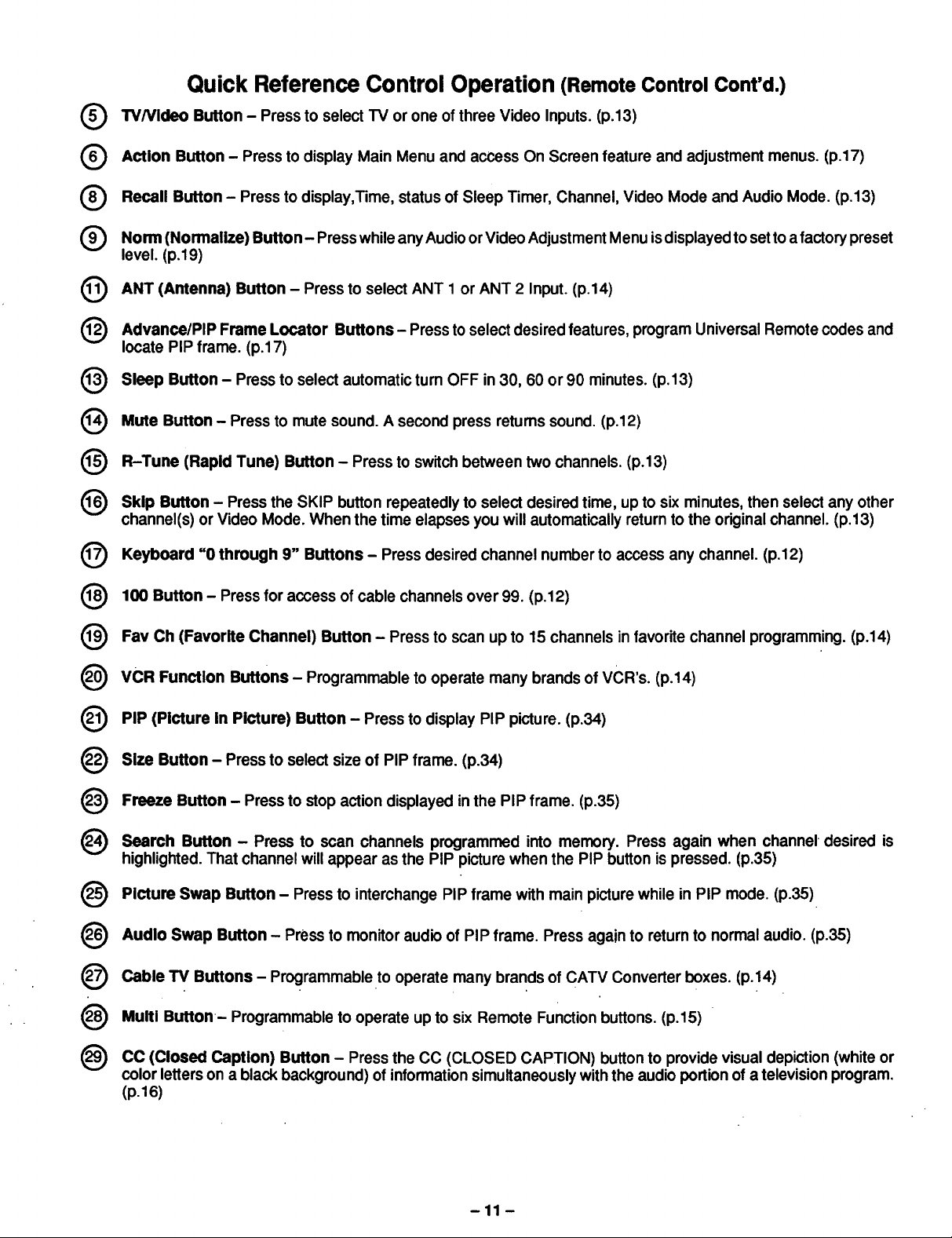
Quick Reference Control Operation (Remote Control Cont'd.)
(_ TVNideo Button - Press to select TV or one of three Video Inputs. (p.13)
(_ Action Button - Press to display Main Menu and access On Screen feature and adjustment menus. (p.17)
Q Recall Button - Press to display,Time, status of Sleep Timer, Channel, Video Mode and Audio Mode. (p.13)
Q orm (Normalize) Button- Press while any Audio or Video Adjustment Menu isdisplayed to setto a factorypreset
level. (p.19)
(_) ANT (Antenna) Button - Press to select ANT 1 or ANT 2 Input. (p.14)
(_ Advance/PIP Frame Locator Buttons - Press to select desired features, program Universal Remote codes and
locate PIP frame. (p.17)
O Sleep Button - Press to select automatic turn OFF in 30, 60 or90 minutes. (p.13)
(_) Mute Button - Press to mute sound. A second press returns sound. (p.12)
R-Tune (Rapid Tune) Button - Press to switch between two channels. (p.13)
(_) Skip Button - Press the SKIP button repeatedly to select desired time, up to six minutes, then select any other
channel(s) or Video Mode. When the time elapses you will automatically return to the original channel. (p.13)
(_) Keyboard "0 through 9" Buttons - Press desired channel number to access any channel. (p.12)
(_) 100 Button - Press for access of cable channels over 99. (p.12)
Fav Ch (Favorite Channel) Button - Press to scan up to 15 channels in favorite channel programming. (p.14)
(_) VCR Function Buttons - Programmable to operate many brands of VCR's. (p.14)
(_ PIP (Picture in Picture) Button - Press to display PIP picture. (p.34)
) ize Button - Press to select size of PIP frame. (p.34)
(_) Freeze Button - Press to stopaction displayed inthe PIP frame. (p.35)
(_) Search Button - Press to scan channels programmed into memory. Press again when channel desired is
highlighted. That channel will appear as the PIP picture when the PIP button ispressed. (p.35)
) Picture Swap Button - Press to interchange PiP frame with main picture while in PIP mode. (p.35)
) udio Swap Button - Press to monitor audio of PIP frame. Press again to return to normal audio. (p.35)
(_ Cable TV Buttons - Programmable to operate many brands of CATV Converter boxes. (p.14)
(_) Multi Button- Programmable to operate up to six Remote Function buttons. (p.15)
(_) CC (Closed Caption) Button - Press the CC (CLOSED CAPTION) button to provide visual depiction (white or
color letters on a black background) of information simultaneously withthe audio portion of a television program.
(p.16)
-11 -
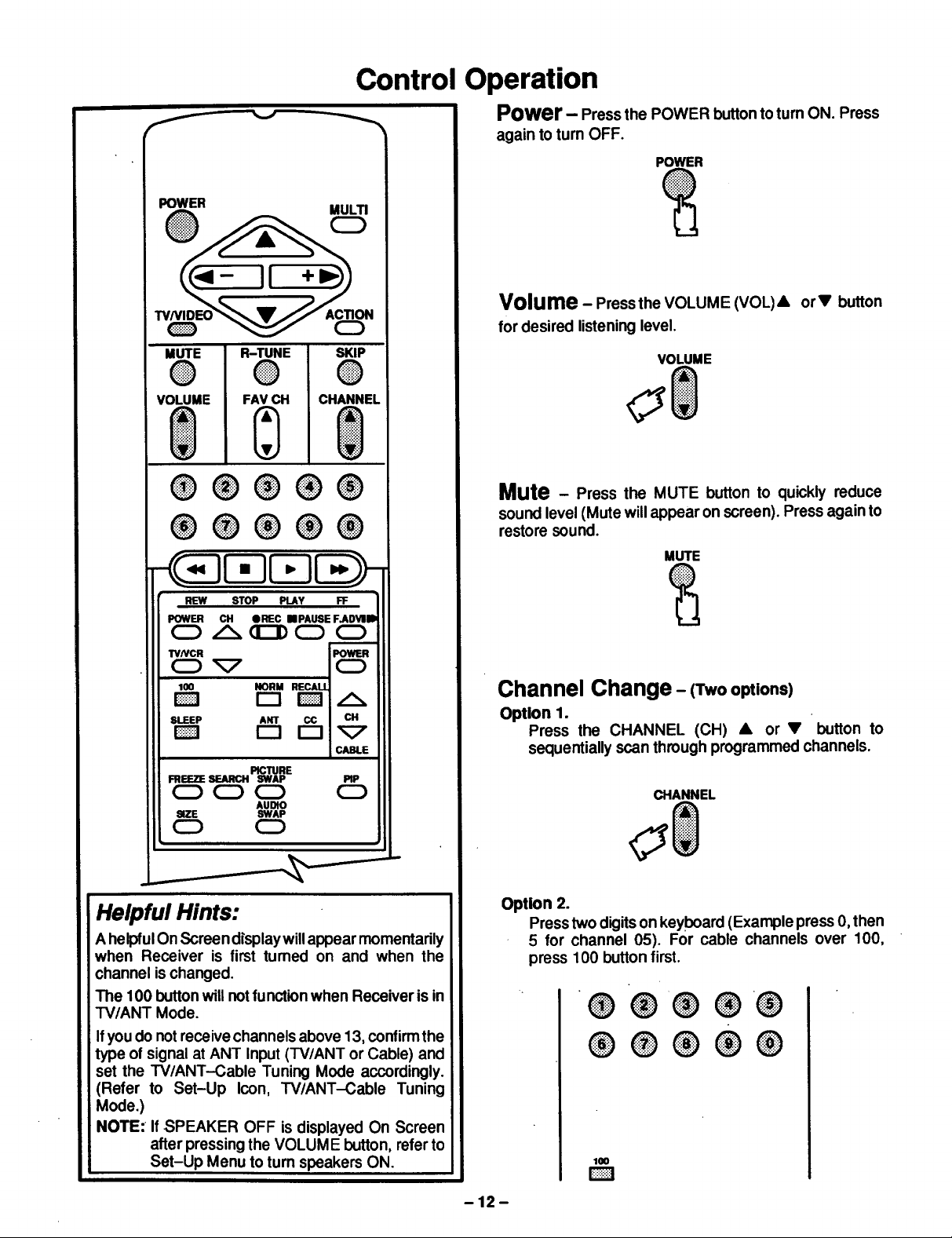
Control Operation
f ---
POWER MULTI
_ _ cD
MUTE
®
VOLUME
R-TUNE SKIP
® @
FAV CH CHANNEL
®®@®@
@®®®@
Power- Press the POWER buttontoturn ON. Press
again to turn OFF.
POWER
Volume - Press the VOLUME (VOL)& orV button
for desired listening level.
VOLUME
Mute - Press the MUTE button to quickly reduce
sound level (Mute will appear on screen). Press again to
restore sound.
MUTE
REW STOP PLAY FF
POWER CH eREC ==PAUSE F.ADVlII)
CD /_ GEDI)CD 0
TVNCR POWER
O_ CD
100 NORM RECALL
SLEEP ANT CC CH
CABLE
FREEZE SEARCH SWAP PIP
OCDC_ 0
SIZE SWAP
PICTURE
AUDIO
CD CD
Helpful Hints:
A helpfulOn Screen display will appear momentarily
when Receiver is first turned on and when the
channel is changed.
The 100 buttonwill notfunction when Receiver is in
TV/ANT Mode.
Ifyou do not receive channels above 13, confirmthe
type of signal at ANT Input (TV/ANT or Cable) and
set the W/ANT-Cable Tuning Mode accordingly.
(Refer to Set-Up Icon, W/ANT-Cable Tuning
Mode.)
NOTE: If SPEAKER OFF is displayed On Screen
after pressing the VOLUME button, refer to
Set-Up Menu to tum speakers ON.
Channel Change- (Two options)
Option 1.
Press the CHANNEL (CH) • or • button to
sequentially scan through programmed channels.
CHANNEL
Option 2.
Press two digitson keyboard (Example press 0,then
5 for channel 05). For cable channels over 100,
press 100 button first.
® ® @ ® ®
®®®®®
D
-12-
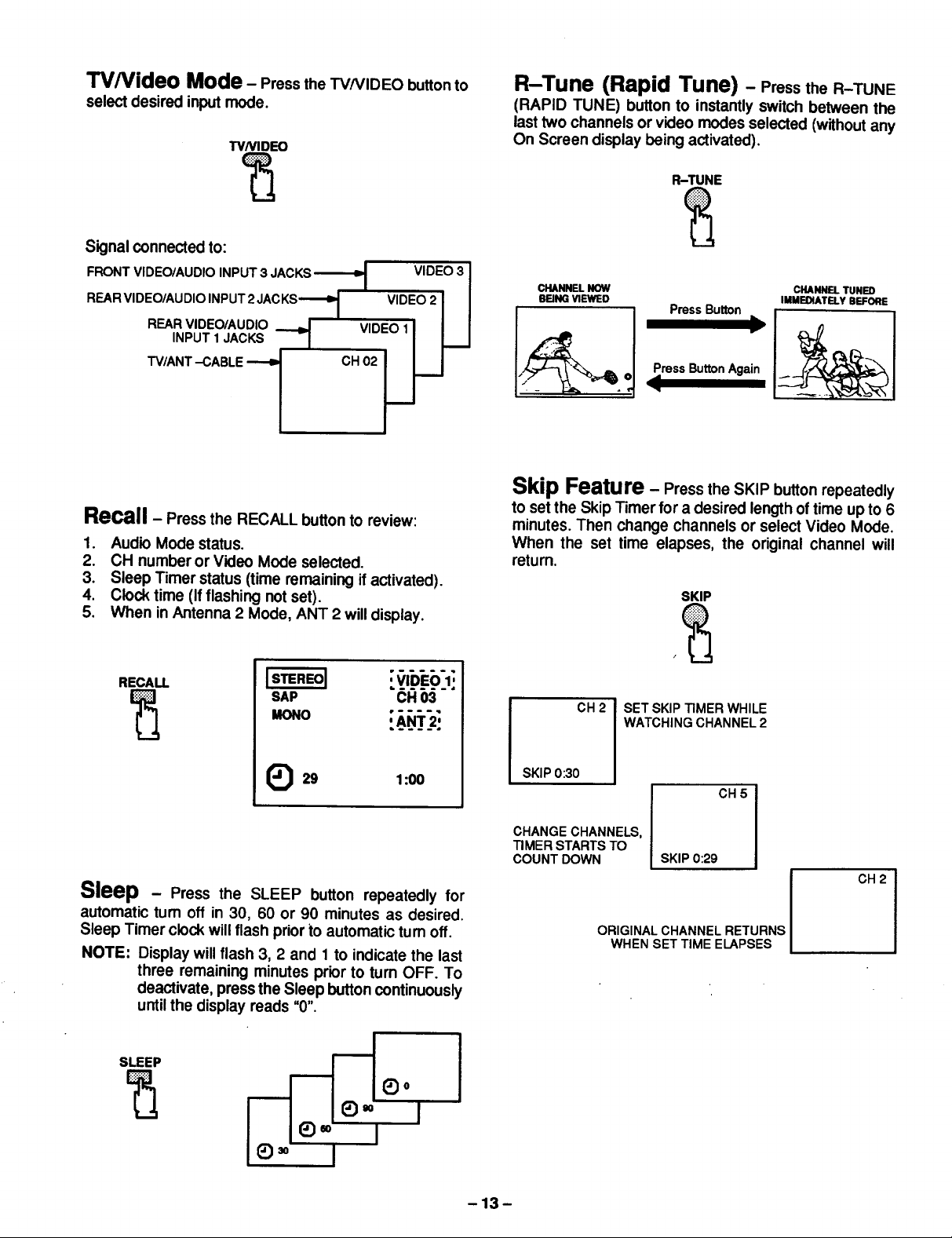
TV/Video Mode - Press the TV/VIDEO buttonto
select desired input mode.
TVNIDEO
Signal connected to:
R-Tune (Rapid Tune) - Press the R-TUNE
(RAPID TUNE) button to instantly switch between the
last two channels or video modes selected (without any
On Screen display being activated).
R-TUNE
FRONT VIDEO/AUDIO INPUT 3 JACKS-_ VIDEO 3 I
REARVIDEO/AUDIOINPUT2JACKS'_I VIDEO2 1 I
REARVIDEO/AUDIO _ VIDEO 11 I I
Recall - Press the RECALL button to review:
1. Audio Mode status.
2. CH number or Video Mode selected.
3. Sleep Timer status (time remaining if activated).
4. Clock time (If flashing not set).
5. When in Antenna 2 Mode, ANT 2 will display.
RECALL
SAP CH 03
CHANNEL NOW
BEING VIEWED
Press ButtonAgain
CHANNEL TUNED
IMMEDIATELY BEFORE
Skip Feature - Press the SKIP buttonrepeatedly
to set the Skip Timer for a desired length of time up to 6
minutes. Then change channels or select Video Mode.
When the set time elapses, the original channel will
return.
SKIP
CH2
SET SKIP TIMER WHILE
WATCHING CHANNEL 2
(_29 1:00
Sleep - Press the SLEEP button repeatedly for
automatic turn off in 30, 60 or 90 minutes as desired.
Sleep Timer clockwill flash prior to automatic turn off.
NOTE: Display will flash 3, 2 and 1 to indicate the last
three remaining minutes prior to turn OFF. To
deactivate, press the Sleep button continuously
until the display reads u0".
SLEEP
_o
SKIP0:30
CHANGE CHANNELS,
TIMER STARTS TO
COUNT DOWN
-13-
CH5
SKIP 0:29
CH2
ORIGINAL CHANNEL RETURNS
WHEN SET TIME ELAPSES
O _ O
MUTE
O
VOLUME
R-TUNE
O
FAV CH
&
®®®®®
®®®®®
SKIP
0
CHANNEL
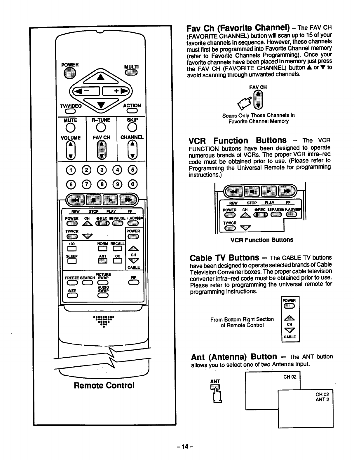
Fav Ch (Favorite Channel) - TheFAVCH
(FAVORITE CHANNEL) button will scan upto 15 of your
favor'dechannels in sequence. However, these channels
must firstbe programmed into Favorite Channel memory
(refer to Favorite Channels Programming). Once your
favorite channels have been placed in memory just press
the FAV CH (FAVORITE CHANNEL) button • or • to
avoid scanning through unwanted channels.
FAV CH
ScansOnlyThoseChannelsIn
FavoriteChannelMemory
VCR Function Buttons - The VCR
FUNCTION buttons have been designed to operate
numerous brands of VCRs. The proper VCR infra-red
code must be obtained prior to use. (Please refer to
Programming the Universal Remote for programming
instructions.)
REW STOP PLAY FF
POWER CH OREC NPAUSE F.ADIP
TVNCR POWER
lOO NORM RECALL
SLEEP ANT CC CH
CABLE
FREEZE SEARCH SWAP PIP
SIZE SWAP
PICTURE
AUDIO
CDCD__
CD CD
Cable TV Buttons - TheCABLETVbuttons
have been designedto operate selected brandsof Cable
Television Converter boxes. The proper cable television
converter infra-red code must be obtained priorto use.
Please refer to programming the universal remote for
programming instructions.
POWER
FromBottomRightSection
ofRemoteControl CH
=
iCABLE
Ant (Antenna) Button - TheANTbutton
• allows you to select one of two Antenna Input.
Remote Control
ANT
CH 02 I
CH 02
ANT 2
-14-
 Loading...