

Page 1
Color Television
Operating Instructions
®
Read these instructions completely before operating this set.
Contents subject to change without notice or obligation.
Printed in U.S.A.
TQB2A09431
Page 2
Safety Instructions
WARNING
WARNING: To reduce the risk of electric shock do not remove cover or back. No
user-serviceable parts inside. Refer servicing to qualified service personnel.
The lightning flash with ar-
is intended to tell the user
_ row-head within a triangle _
that partsinside the product
are ariskofelectric shockto
persons.
The exclamation point within
a triangle is intended to tell
the userthat important oper-
ating and servicing instruc-
tions are in the papers with
the appliance.
Note To CATV System Installer: This reminder isprovided to call the CATV system installer's attentionto Article
820-40 ofthe NEC that provides guidelines for proper grounding and, inparticular, specifies that the cable ground shall be
connected to the grounding system of the building, as closeto the point of cable entry as practical.
Safety Instructions For Television Receivers
1. Read and apply the operating instructions provided with your television receiver.
2. Read all ofthe instructions given here and retain them for later use.
3. Unplug this television receiver from the wall outlet before cleaning. Do not use liquid or aerosol cleaners. Use a damp
clothfor cleaning.
4. Do not use attachments not recommended bythe television receiver manufacturer as they may cause hazards.
5. Do not use this television receiver near water. For example: Avoid placing it near a bathtub, washbowl, kitchensink,or
laundrytub, in a wet basement, or near a swimming pool, etc.
6. Do notplace thistelevision receiver on an unstable cart,stand, o_table. The television receiver may fall, causingserious
injuryto a childor adult, and serious damage to the appliance. Use only with a cart or stand recommended by the
manufacturer, or sold with the television receiver. Wall or shelf mounting shouldfollow the manufacturer'sinstructions,
and should use a mounting kit approved by the manufacturer.
6A. An appliance and cart combination should be moved with care. Quick stops, excessive force, and
uneven surfaces may cause the appliance and cart combination to overturn.
7. Slots and openings in the cabinet and the back or bottom are provided for ventilation, and to insure
reliable operation of the television receiver and to protect it from overheating. These openings must not be blocked or
covered. The openings should never be blocked by placing the television receiver on a bed, sofa, rug or other similar
surface_ This television receiver should never be placed near or over a radiator or heat register. This television receiver
should not be placed in a built-in installation such as a bookcase unless proper ventilation is provided.
8. Operate only from the type of power source indicated on the marking label. If you are not sure of the type of power
supplied to your home consult your television dealer or local power company. For television receivers designed to
operate from battery power, refer to the operating instructions.
9. This television receiver is equipped with a polarized alternating-current line plug (a plug having one blade wider than the
other). This plug will fit into the power outlet only one way. This is a safety feature. If you are unable to insert the plug
fully into the outlet, try reversing the plug. If
the plug should still fail to fit, contact your
electricianto replaceyourobsolete outlet. Do
notdefeat the safetypurpose of the polarized
plug.
10. Do not allow anything to rest on the power
cord. Do not locate this television receiver
where the cord will be abused by persons
walking on it.
11. Follow all warnings and instructions marked
on the television receiver.
12. Do not overload wall outlets and e_ension
cords as this can result in fire or electric
shock.
13. Never push objects of any kind into this
television receiver through cabinet slots as
they may touch dangerous voltage points or
short out parts that could result in a fire or
electric shock. Never spill liquidofany kind on
the television receiver.
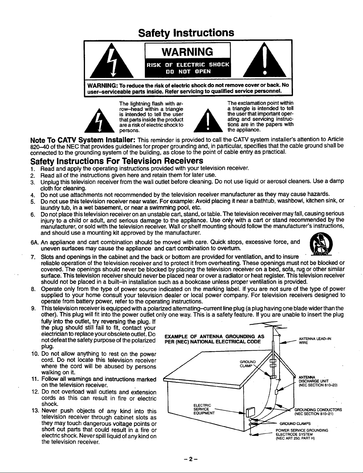
EXAMPLE OF ANTENNA GROUNDING AS _ ANTENNALEAD-IN
PER (NEC) NATIONAL ELECTRICAL COD E _ _RE
// . _l_]_],,,,I.__, _1 ANTENNA •
/ ! I _/" j. DISCHARGEUNIT
I ELECTRIC / /_= I
_.._..,._ENT _ _ (I E SECTION 810-21)
EQUIPMENT N C
_ GROUND CLAMPS
_ • POWER SERVICE GROUNDING
---L.,._l--"-'--"_ ELECTRODE SYSTEM
(NEC ART 250, PART H)
CO. CTO,S
-2-
Page 3
14.Ifanoutside antenna is connected to the television equipment, be sure the antenna system isgrounded so asto provide
some protection against voltage surges and built up static charges. In the U.S. Section 810 of the National Electrical
Code and inCanada Part 1 ofthe Canadian Electrical Code provides informationwith respect to proper groundingof the
mast and supportingstructure, grounding of the lead-in wireto an antenna discharge unit,size ofgroundingconductors,
locationofantenna-discharge unit, connectionto grounding electrodes, and requirements for thegrounding electrode.
See Figure.
15. For added protectionfor thistelevision receiver duringa lightningstorm, or when it is left unattended and unusedfor long
periodsoftime, unplugitfrom the wall outletand disconnectthe antenna. This willprevent damage tothe receiverdue to
lightning and power-line surges.
16. An outside antenna system should not be located inthe vicinityof overhead power lines or other electric lightor power
circuits,or where it can fall intosuch power lines or circuits.When installingan outside antenna system extreme care
should be taken to keep from touching such power lines or circuits as contact with them might be fatal.
17. Unplugthis television receiverfrom the wall outlet, and refer servicing to qualifiedservice personnel underthe following
conditions:
a. When the power cord or plug is damaged or frayed.
b. If liquidhas been spilled intothe television receiver.
c. Ifthe television receiver has been exposed to rain or water.
d. Ifthe television receiver does notoperate normally by following the operating instructions.Adjustonlythose controls
thatare covered bythe operating instructionsas improper adjustment ofothercontrols may resultindamage and will
often require extensive work by a qualified technician to restore the television receiver to normal operation.
e. Ifthe television receiver has been dropped or the cabinet has been damaged.
f. When the television receiver exhibits a distinct change in performance - thisindicates a need for service.
18. Do notattempt to service this television receiver yourself as opening or removingcovers may expose you to dangerous
voltage or other hazards. Refer all servicing to qualified service personnel.
19. When replacement parts are required, be sure the service technician has used replacement parts specified by the
manufacturer that have the same characteristics as the original part. Unauthorized substitutions may result in fire,
electric shock, or other hazards.
20. Upon completion of any service or repairs to this television receiver, ask the service technician to perform routine safety
checks to determine that the television is in safe operating condition.
21. WARNING: To prevent fire or shock hazard, do not expose this appliance to rain or moisture.
22. CAUTION: TO PREVENT ELECTRIC SHOCK DO NOT USE THIS (POLARIZED) PLUG WITH AN RECEPTACLE OR
OTHER OUTLET UNLESS THE BLADES CAN BE FULLY INSERTED TO PREVENT BLADE EXPOSURE.
NOTE: Thisequipment is designed to operate inthe U.S.A., Canada and other countrieswhere the broadcastingsystem and
AC housecurrent is exactly the same as inthe U.S.A. and Canada.
Important Information Regarding Use of Video Games, Computers, Teletext or Other Fixed Image Displays.
The extended use of fixed image program material can cause a permanent "shadow image" on the picture tube. This
backgroundimage isviewable on normalprograms in the formof a stationary fixed image. This type of irreversible picture
tube deterioration can be limited by observing the following steps:
A, Reduce the brightness/contrast setting to a minimum viewing level.
B, Do not display the fixed image for extended periods oftime.
C. Turn the power offwhen not in actual use.
NOTE: The marking or retained image on the picture tube resultingfrom fixed image use is not an operating defect and as
suchisnotcovered by Warranty. This product is notdesigned todisplay fixedimage patterns forextended periodsof
time.
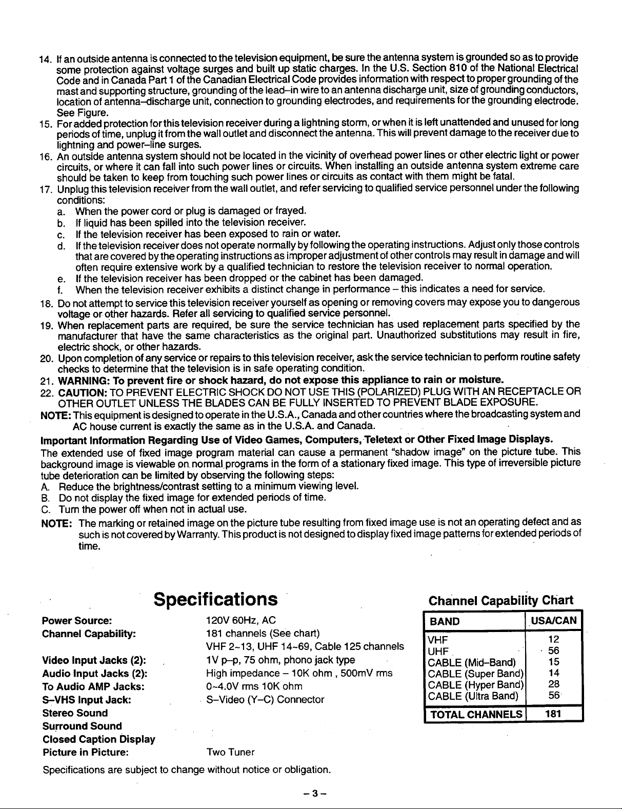
Specifications
Power Source:
Channel Capability:
Video Input Jacks (2):
Audio Input Jacks (2):
To Audio AMP Jacks:
S-VHS Input Jack:
Stereo Sound
Surround Sound
Closed Caption Display
Picture in Picture:
Specifications are subject to change without notice or obligation.
120V 60Hz, AC
181 channels (See chart)
VHF 2-13, UHF 14-69, Cable 125 channels
1V p-p, 75 ohm, phono jack type
High impedance - 10K ohm, 500mV rms
0-4.0V rms 10K ohm
. S-Video (Y-C) Connector
Two Tuner
-3-
Channel Capability Chart
BAND USA/CAN
VHF 12
UHF • 56
CABLE (Mid-Band) 15
CABLE (Super Band) 14
CABLE (Hyper Band) 28
CABLE (Ultra Band) 56
TOTAL CHANNELS 181
Page 4
Introduction
Congratulations on Your New Purchase
Yournew video component features an all solid state chassis which is designed to give you many years ofenjoyment. It
was thoroughlytested and adjusted at the factory for best performance.
In order foryou totake fulladvantage of your new video component, please read and followthe installationand operating
instructionssupplied with this product.
Customer's Record
The model and serial number ofthis product may be found on itsback cover.Youshouldnotethe model and serial number
inthe space provided and retain this book as a permanent record of your purchase to aid in identificationin the event of
theft or loss.
Model Number:
Table of Contents
Safety Instructions ............................. 2
Specifications ................................. 3
Introduction ................................... 4
Installation ........ ...... ...................... 5
Receiver Location .............................. 5
Optional Extemal Equipment Connections ........ 5
AC Power Supply Cord ......................... 5
Battery Installation ............................. 5
Antenna/Cable Connections ..................... 6
Picture in Picture External Video & Ant Connection. 7
Location of Controls (Remote) .................. 8
Location of Controls (Receiver) ................. 9
Quick Reference Control Operation .............. 9
Control Operation . ............ . .... : .......... 10
Power Button ....... : ......................... 10
Volume (Vol) Buttons .......................... 10
Mute Button .................................. 10
Channel Change Features ..................... 10
Channel (Ch) Buttons ....................... 10
Keyboard "0 through 9" Buttons .............. 10
VCR Function Buttons ......................... 10
"l'Vfideo Button .............................. 11
Recall Button ................................. 11
R-Tune(Rapid Tune) Button ................... 11
Multi Button .................................. 11
Cable (TV) Power Button ...................... 12
PIP (Picture in Picture) Button .................. 12
PIP Channel Buttons .......................... 12
PIP Swap Button ....... : ..................... 12
PIP Size Button ............................... 13
PIP Freeze Button ............................ 13
PIP Move Button............................... 13
PIP Search Button ............................ 13
Main Menu(Icons) ............................ 14
Picture Adjustments ........................... 15
Color ...................................... 15
Tint ....................................... 15
Brightness ................................. 15
Serial Number:
Picture .................................... 15
Sharpness ................................. 15
Picture Norm ............................... 15
Game Guard ....... . ........ . ................ 16
Game Guard (Lockout) ...................... 16
Game Guard (Unlock) ....................... 17
Timer Features .......................... ..... 18
Sleep Timer ................................ 18
Program Timer ............................. 19
Set-Up Features ............................. 20
Menu ..................................... 20
CC (Closed Caption) On Mute ................. 21
Set Time (Clock) ............................ 22
Antenna Tuning Mode ....................... 23
Auto Programming ............. _............ 24
Manual Programming ................ ....... . 25
CC (Closed Caption) Mode .................. 26
Channel Caption (Station Identifier) ............. 27
Audio Adjustments ............................ 28
Bass, Treble & Balance Adjustments .......... 28
Audio Norm ................................ 28
Audio Mode Selection (Stereo/SAP/Mono) .... 29
[TV] Speaker... ............................ 29
Surround Sound ............................ 30
AI Sound .................................. 30
Input Select .................................. 31
Main (picture) Input Selection ................ 31
PIP Input Selection ......................... 31
Programming The Universal Remote Control .... 32
VCR, LDP & Cable Converter Box
Infra-Red Codes .......................... 33
Optional Equipment Connection & Operation ... 34
Stereo Connection (To Audio AMP) . ,.. ......... 34
Video/Audio Connection ....................... 34
S-Video Connection .......................... 35
Care & Cleaning ................. ............... 35
Power Loss ................................... 35
Troubleshooting Chart ........................ 36
Page 5
\\
Installation
Receiver Location
Locate for comfortable viewing. Avoid placing where sunlightor other brightlight(including reflections) will fall on the
screen.
Use of some types of fluorescent lighting can reduce remote control transmitter range.
Adequate ventilation is essential to prevent internal component failure. Keep away from areas of excessive heat or
moisture.
To insure optimum color purity do not position magnetic equipment (motors, fan, other speakers, etc.) nearby.
Optional External Equipment Connections
The Video/Audio connections between components can be made with shielded videoand audio cables. For best perfor-
mance, video cables should utilize 75 ohm coaxial shielded wire. Cables are available from your dealer or electronic
supply house.
Before you purchase any cables, be sure you know what type of output and input connectors your various components
require. Also determine the length of cable you'll need.
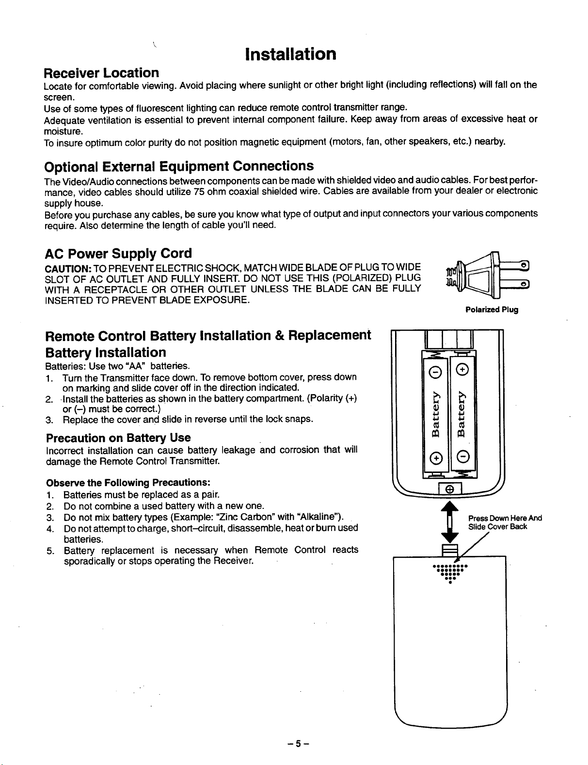
AC Power Supply Cord
CAUTION: TO PREVENT ELECTRIC SHOCK, MATCH WIDE BLADE OF PLUG TO WIDE
SLOT OF AC OUTLET AND FULLY INSERT. DO NOT USE THIS (POLARIZED) PLUG
WITH A RECEPTACLE OR OTHER OUTLET UNLESS THE BLADE CAN BE FULLY
INSERTED TO PREVENT BLADE EXPOSURE.
Polarized Plug
Remote Control Battery Installation & Replacement
Battery Installation
Batteries: Use two "AA" batteries.
1. Turn the Transmitter face down. To remove bottom cover, press down
on marking and slide cover off in the direction indicated.
2. Install the batteries as shown in the battery compartment. (Polarity (+)
or (-) must be correct.)
3. Replace the cover and slide in reverse untilthe lock snaps.
Precaution on Battery Use
Incorrect installation can cause battery leakage and corrosion that will
damage the Remote Control Transmitter.
Observe the Following Precautions:
1. Batteries must be replaced as a pair.
2. Do not combine a used battery with a new one.
3. Do not mix battery types (Example: "Zinc Carbon" with "Alkaline").
4. Do not attempt tocharge, short-circuit, disassemble, heat or bum used
batteries.
5. Battery replacement is necessary when Remote Control reacts
sporadically or stops operating the Receiver.
II I I!1
®
®
€
€
®
®
Slide Cover Back
Press Down Here And
-5-
J
Page 6
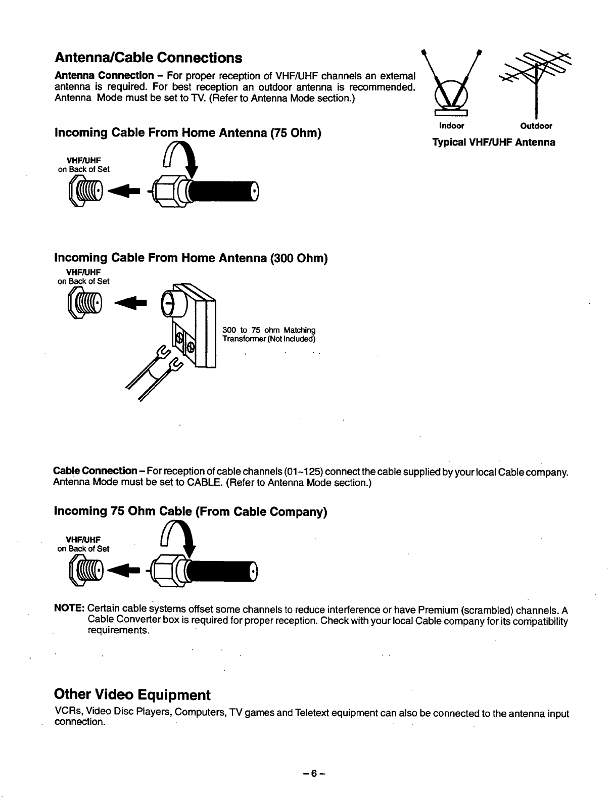
Antenna/Cable Connections
Antenna Connection - For proper reception of VHF/UHF channels an external
antenna is required. For best reception an outdoor antenna is recommended.
Antenna Mode must be set to TV. (Refer to Antenna Mode section.)
Incoming Cable From Home Antenna (75 Ohm)
VHF/UHF
on Back of Set
Incoming Cable From Home Antenna (300 Ohm)
VI-IF/UHF
on Back of Set
@
300 to 75 ohm Matching
Transformer (Not Included)
Indoor Outdoor
Typical VHF/UHF Antenna
Cable Connection - For reception of cable channels (01-125) connect the cable supplied byyourlocalCable company.
Antenna Mode must be set to CABLE. (Refer to Antenna Mode section.)
Incoming 75 Ohm Cable (From Cable Company)
VHFAIHF
on Back of Set
NOTE: Certain cable systems offset some channels to reduce interference or have Premium (scrambled) channels. A
Cable Converter box is required for proper reception. Check with your local Cable company for its compatibility
requirements.
Other Video Equipment
VCRs, Video Disc Players, Computers, TV games and Teletext equipment can also be connected to the antenna input
connection.
-6-
Page 7
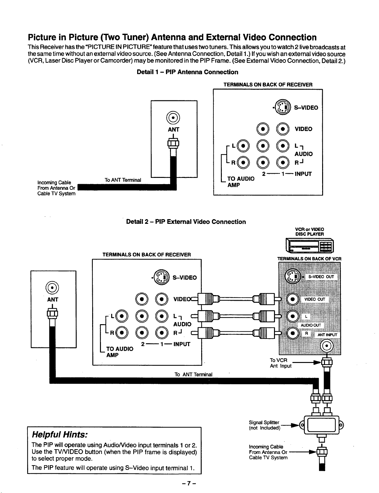
Picture in Picture (Two Tuner) Antenna and External Video Connection
ThisReceiver hasthe "PICTURE INPICTU RE"feature that uses two tuners. This allowsyou to watch 2 live broadcastsat
thesame time without anexternalvideo source. (See Antenna Connection, Detail 1.) Ifyou wish anexternal videosource
(VCR, Laser Disc Player orCamcorder) may be monitored in the PIP Frame. (See ExternalVideo Connection, Detail2.)
Detail I - PIP Antenna Connection
TERMINALS ON BACK OF RECEIVER
•@ S-VIDEO
®
Incoming Cable
From Antenna Or
Cable TV System
To ANT Terminal
ANT
L I.- 1
r ® ® ®,°o,o
[-L.®® ®.,
LTO 2_ 1-- INPUT
AUDIO
AMP
® ® v,ooo
@
ANT
Detail 2 - PIP Extemal Video Connection
TERMINALS ON BACK OF RECEIVER
•@ S-VIDEO
® ® v,ooo_
AUDIO
.® ® ®..
,® ®®,_ _
O AUDIO
AMP
2 _ 1B INPUT
To ANT Terminal
VCR or VIDEO
DISC PLAYER
TERMINALS ON BACK OF VCR
AUDIO OUT
ToVCR
Ant Input
Helpful Hints:
The PIP will operate using Audio/Video input terminals I or2.
Use the W/VIDEO button (when the PIP frame is displayed)
to select proper mode.
The PiP feature will operate usingS-Video input terminal 1.
AA
Signal Splitter
,oot,nc,uo ,
V
From Antenna Or
Cable "IV System
Incoming Cable
Page 8
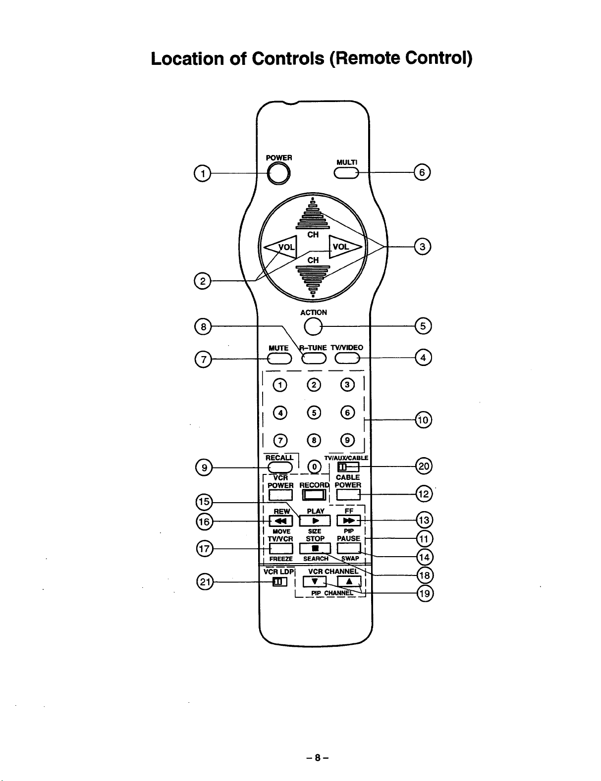
Location of Controls (Remote Control)
POWER
®
®
O MULTI
ACTION
CD ®
®
®
®
@
®
®
@
__ T VNIDEO
CD
® ® ®
® ® ®
® ® ®
"_-CA_------_ I"VIAUYJCABLE
__j_®_ _
VCR CABLE
POWER RECORD POWER
FF 1
MOVE SIZE PIP I
FREEZE SEARCH _"_W_ AP I
VCR LDPJ VCR CHANNEL-'_'_
L
I-_-I!
STOP PAUSE i
®
@
@
,
@
@
®
®
®
J
8
Page 9
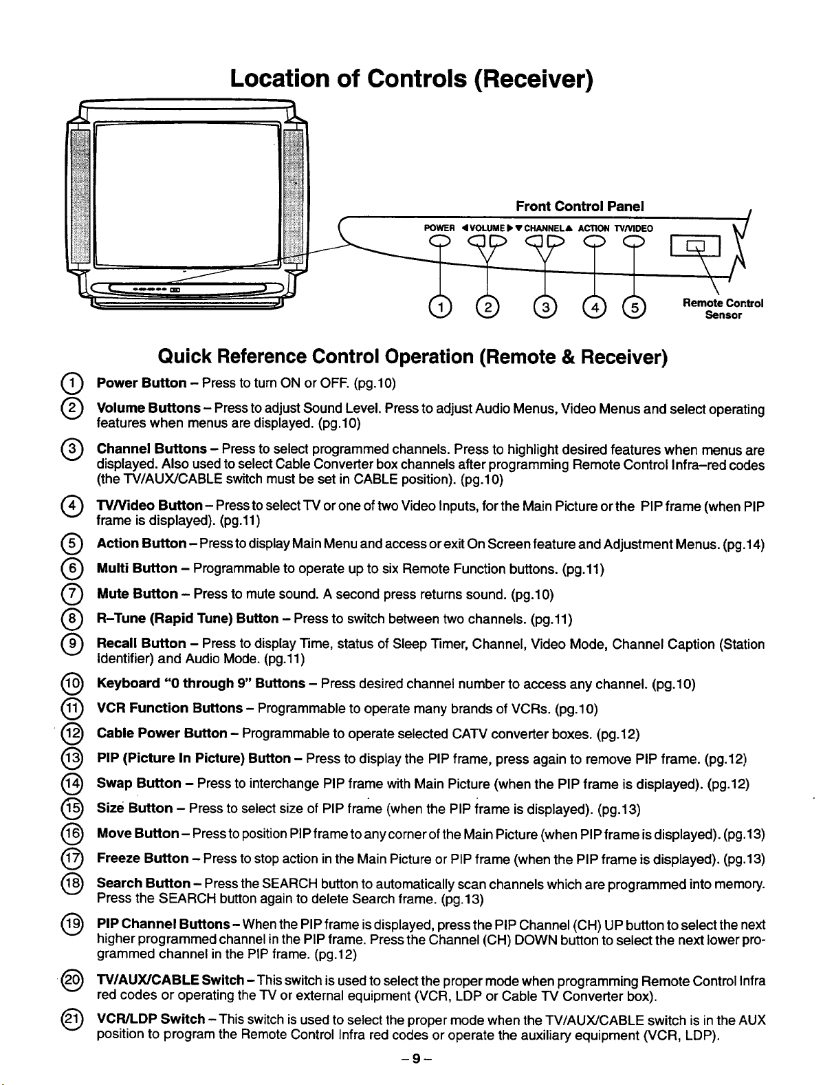
Location of Controls (Receiver)
Front Control Panel
L
L
POWER <I VOLUME I_ V CHANNEL& ACTION TVMD_O
Remote Control
Sensor
Quick Reference Control Operation (Remote & Receiver)
Power Button Press to turn ON OFF.
Volume Buttons Press to Sound Level. Press Audio
features when menus are displayed. (pg.10)
Channel Buttons - Press to select channels. Press to desired features
displayed. Also usedto selectCable Converter boxchannels after programming Remote Control Infra-red codes
(the TV/AUX/CABLE switchmustbe set in CABLE position). (pg.lO)
Q TWVideo Button-Press to select TV oftwo Video for the Main Picture the PIP frame PIP
frame is displayed). (pg.11)
Action Button Pressto Main Menu and exit On Screen feature
Multi Button - to to six Remote Function buttons.
Mute Button Press to mute sound. A second returns sound.
(Rapid Tune)
@
@
-@
@
R-Tune Button - Press to switch between two channels.
Recall Button - Press to Time, status of Video Channel
Identifier) and Audio Mode. (pg.11)
Keyboard "0 through 9" Buttons - Press desired channel number to access any channel. (pg.10)
VCR Function Buttons - Programmable to operate many brands of VCRs. (pg.10)
Cable Power Button - Programmable to operate selected CATV converter boxes. (pg.12)
PIP (Picture In Picture) Button - Press to display the PIP frame, press again to remove PIP frame. (pg.12)
- adjust to adjust Menus, Video Menus and select operating
display
Programmable operate
display Sleep
or
(pg.10)
programmed
or one
access or and
up (pg.11)
press (pg.10)
Inputs,
Timer,
highlight
Channel, Mode, Caption (Station
(pg.11)
or
Adjustment
when menus are
(when
Menus.
(Pg.14)
Swap Button - Press to interchange PIP frame withMain Picture (when the PIP frame is displayed). (pg.12)
@
size Button - Press to select size of PIP frame (when the PIP irame isdisplayed). (pg.13)
@
Move Button- Press to positionPIP frame to anycomer ofthe Main Picture(when PIP frame isdisplayed). (pg.t 3)
@
Freeze Button - Press to stopaction inthe Main Pictureor PIP frame (when the PIP frame is displayed). (pg.13)
@
@
Search Button - Pressthe SEARCH buttonto automatically scanchannels which are programmed intomemory.
Press the SEARCH buttonagain to delete Search frame. (pg.13)
PIP Channel Buttons When the PIP
higher programmed channel in the PIP frame. Press the Channel (CH) DOWN button toselect the next lower pro-
grammed channel inthe PIP frame. (pg.12)
TV/AUX/CABLE Switch -This switchis usedto selectthe proper mode when programming Remote Control Infra
red codes or operating theTV or external equipment (VCR, LDP or Cable TV Converter box).
VCR/LDP Switch - This switchisused toselect the proper mode when the TV/AUX/CABLE switch is inthe AUX
position to program the Remote Control Infra red codes or operate the auxiliary equipment (VCR, LDP).
- is displayed, press the PIP Channel (CH) UP button to select the next
frame
-9-
Page 10
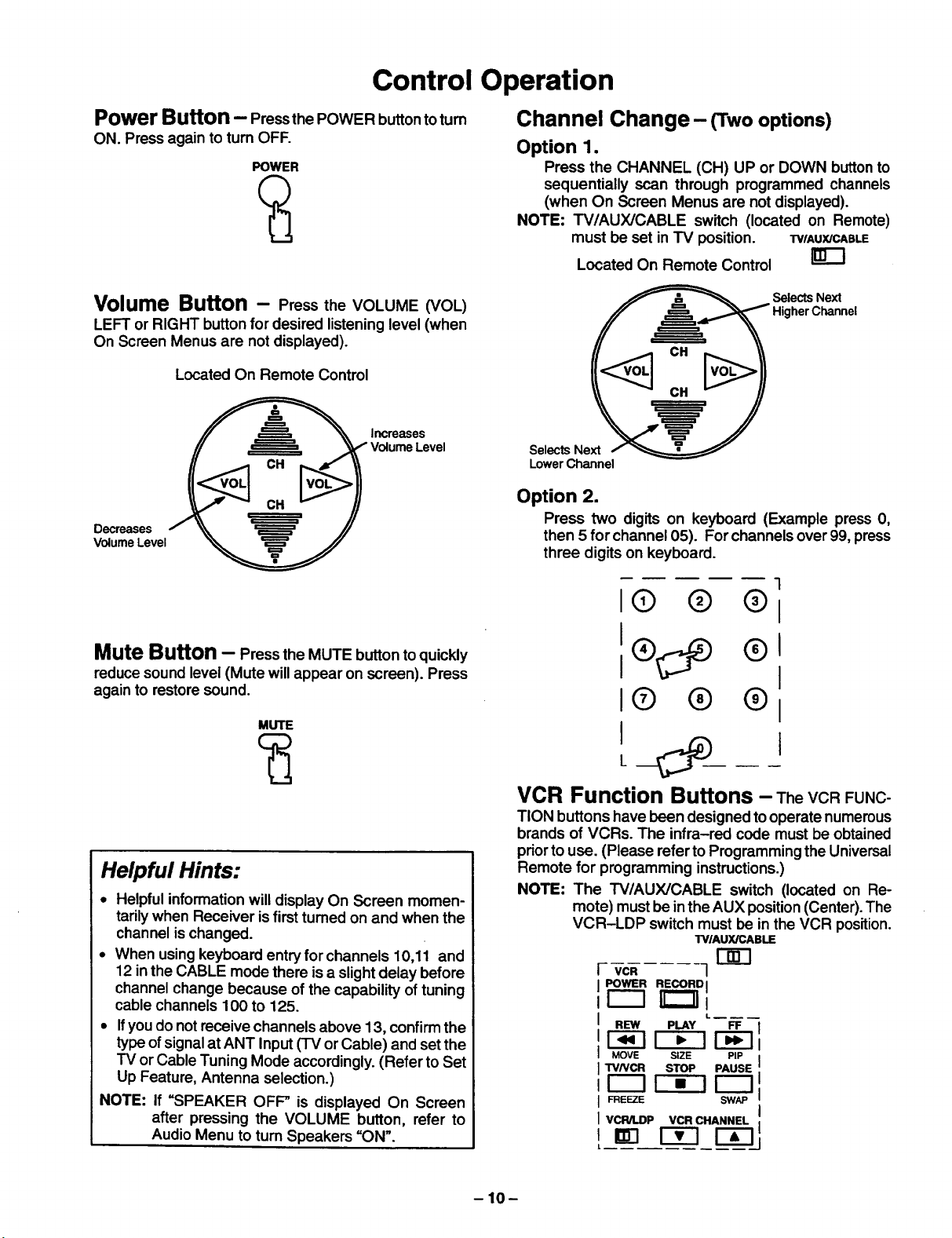
Control Operation
Power Button - Pressthe POWER button to tum
ON. Press again to turn OFF.
POWER
Volume Button - Press the VOLUME (VOL)
LEFT or RIGHT button for desired listening level (when
On Screen Menus are not displayed).
Located On Remote Control
Increases
Volume Level
Decreases
Volume Level
Channel Change- (Twooptions)
Option 1.
Press the CHANNEL (CH) UP or DOWN buttonto
sequentially scan through programmed channels
(when On Screen Menus are not displayed).
NOTE: TV/AUX/CABLE switch (located on Remote)
must be set in TV position. "FVlAUX/CABLE
Located On Remote Control
_ Selects Next
___ Higher Channel
Selects Next / _=€=====T=======__
Lower Channel
Option 2.
Press two digits on keyboard (Example press 0,
then 5 for channel 05). For channels over 99, press
three digits on keyboard.
Mute Button - Press the MUTE button to quickly
reducesound level (Mute will appear on screen). Press
againto restore sound.
MUTE
Helpful Hints:
• Helpful informationwill display On Screen momen-
tarilywhen Receiver is firstturned on and when the
channel ischanged.
• When usingkeyboard entry for channels 10,11 and
12 in the CABLE mode there is a slightdelay before
channel change because of the capability of tuning
cable channels 100 to 125.
• Ifyou do not receive channels above 13, confirmthe
typeofsignal at ANT Input (TV or Cable) and setthe
TV or Cable Tuning Mode accordingly.(Refer to Set
Up Feature, Antenna selection.)
NOTE: If =SPEAKER OFF" is displayed On Screen
after pressing the VOLUME button, refer to
Audio Menu to turn Speakers =ON".
1
I@ @ ®1
I1® ®1
I(D ® ®1
I
L
VCR Function Buttons - TheVCRFUNC-
TIONbuttons have been designed tooperate numerous
brands of VCRs. The infra-red code must be obtained
priorto use. (Please referto Programming the Universal
Remote for programming instructions.)
NOTE: The "I'V/AUX/CABLE switch (located on Re-
mote) must be inthe AUX position(Center). The
VCR-LDP switch must be in the VCR position.
TV/AUX/CABLE
r-_
VCR 1
POWER RECORD I
REW PLAY FF
_-lr-_ F-_
MOVE SIZE PIP
TVNCR STOP PAUSE
_E_E SW_
VCR/LDP VCR CHANNEL ,
-10-
Page 11
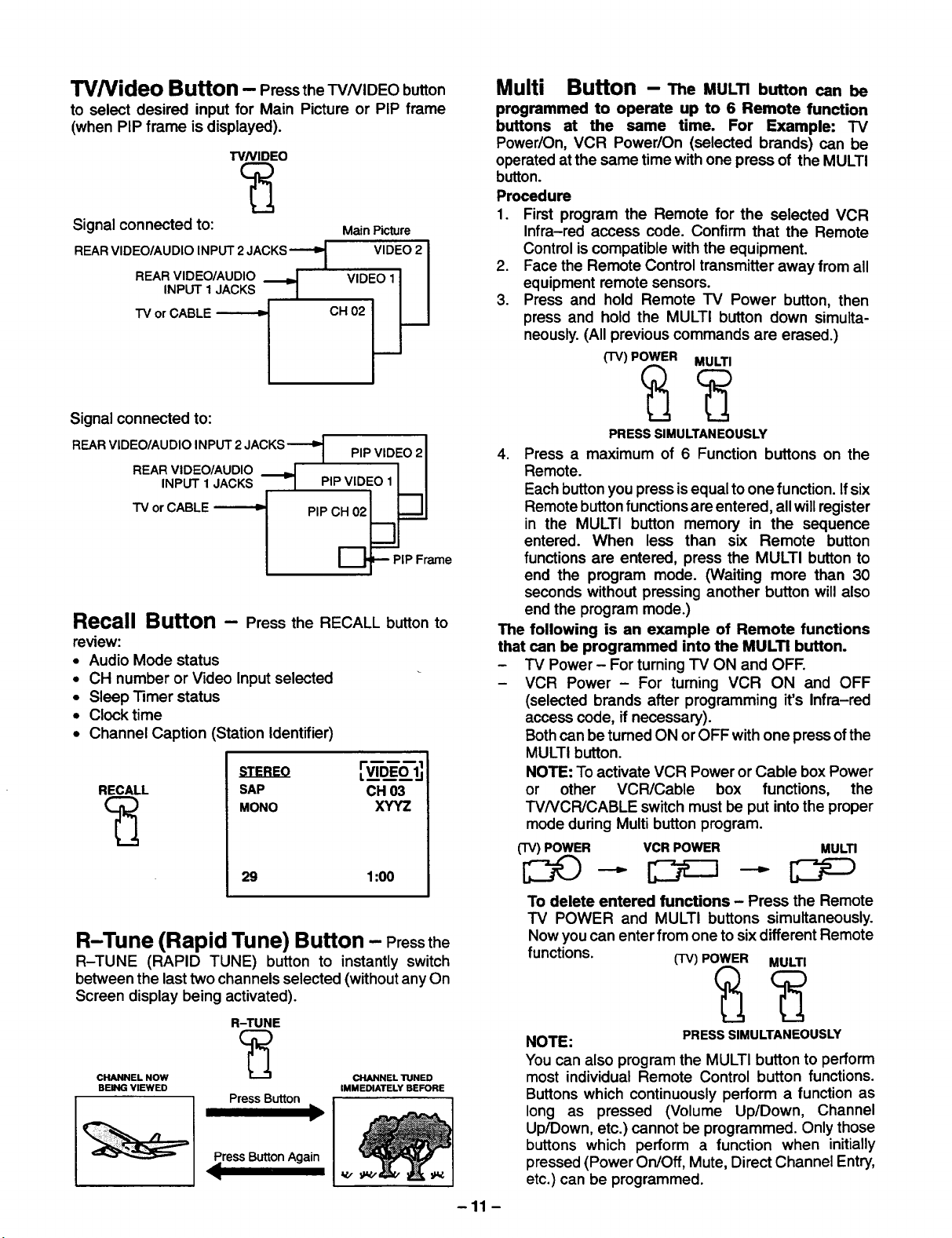
TV/Video Button - Pressthe TVNIDEO button
to select desired input for Main Picture or PIP frame
(when PIP frame is displayed).
TVNIDEO
-Signal connected to: MainPicture
REAR VIDEO/AUDIO INPUT 2 JACKS
INPUT 1 JACKS
REAR VIDEO/AUDIO _
TV or CABLE
/
VIDEO 2 I
::o li
Multi Button -- The MULTI button can be
programmed to operate up to 6 Remote function
buttons at the same time. For Example: TV
Power/On, VCR Power/On (selected brands) can be
operated at the same time with one press of the MULTI
button.
Procedure
1. First program the Remote for the selected VCR
Infra-red access code. Confirm that the Remote
Control iscompatible with the equipment.
2. Face the Remote Control transmitter away from all
equipment remote sensors.
3. Press and hold Remote TV Power button, then
press and hold the MULTI button down simulta-
neously.(All previous commands are erased.)
(TV) POWER MULTI
Signal connected to:
REAR VIDEO/AUDIO INPUT 2 JACKS-"-'D 1 PiPVlDEO 21
REAR VIDEO/AUDIO -I I I
INPUT 1JACKS _ PIP VIDEO 1 _II
TV or CABLE _ PIP CHr_02_.J
I_=--- PIP Frame
Recall Button - Press the RECALL button to
review:
• Audio Mode status
• CH number or Video Input selected
• Sleep Timer status
• Clock time
• Channel Caption (Station Identifier)
RECALL SAP CH 03
MONO XYYZ
29 1:00
R-Tune (Rapid Tune) Button - Pressthe
R-TUNE (RAPID TUNE) button to instantly switch
between the last two channels selected (without anyOn
Screen display being activated).
R-TUNE
c;2
CHANNEL NOW _ CHANNEL TUNED
BEING VIEWED IMMEDIATELY BEFORE
PressButton
Press Button Again
<
)
V.x
PRESS SIMULTANEOUSLY
4. Press a maximum of 6 Function buttons on the
Remote.
Each buttonyou press is equal toone function. Ifsix
Remote buttonfunctionsare entered, all will register
in the MULTI button memory in the sequence
entered. When less than six Remote button
functions are entered, press the MULTI button to
end the program mode. (Waiting more than 30
seconds without pressing another button will also
end the program mode.)
The following is an example of Remote functions
that can be programmed into the MULTI button.
- TV Power- For turning "IV ON and OFF.
- VCR Power - For turning VCR ON and OFF
(selected brands after programming it's Infra-red
access code, ifnecessary).
Bothcan be turned ON or OFF with one press of the
MULTI button.
NOTE: To activate VCR Power or Cable box Power
or other VCR/Cable box functions, the
TV/VCR/CABLE switch must be put intothe proper
mode during Multi button program.
(TV) POWER VCR POWER MULTI
To delete entered functions - Press the Remote
TV POWER and MULTI buttons simultaneously.
Now you can enter from one to six different Remote
functions. (-rv)POWER MULTI
NOTE:
You can also program the MULTI button to perform
most individual Remote Control button functions.
Buttons which continuously perform a function as
long as pressed (Volume Up/Down, Channel
Up/Down, etc.) cannot be programmed. Only those
buttons which perform a function when initially
pressed (Power On/Off, Mute, Direct Channel Entry,
etc.) can be programmed.
-11 -
PRESS SIMULTANEOUSLY
Page 12

Cable Power Button - The CABLE Power
button on the Remote Control has been designed to
operate selected brands of Cable Converter Boxes. The
proper Cable Converter Box infra-red code must be
obtained priorto use. (Please refer to Programming the
Universal Remote for programming instructions.)The
TV/AUX/CABLE switch should be in the cable position.
NOTE: Use the Channel UP and DOWN buttonson the
Remote for selecting Cable Converter Box
Channels. CASLE
Located On Remote Control I-JIh-"l
POWER
Use to select Cable Box
Channels afterprogramming
Infra-red Code.
PIP Channel Buttons - Pressthe(PIP)CH
(CHANNEL) UP or DOWN buttonwhile the PIP frame is
displayed to sequentially scan through Channels.
Scan Channel DOWN Scan Channel Up
(nextlower) (nexthigher)
PIP Swap Button - Press the SWAP button
(when the PIP frame is displayed) tointerchange what is
being viewed on the Main Picture with that of the PIP
frame.
PIP (Picture in Picture) Button--This
feature allows the viewer to monitor one channel
program while watching another. The monitoredsource
(PIP) can be a different channel or a different video
source (such as a VCR) when connected to the input
jacks.
• The TV/AUX/CABLE Switch should be in the TV
position (LEFT) before operating PIP buttons.
• S-Video connectionwill also operate the PIP feature
(refer to OPTIONAL S-VIDEO VHS CONNECTION
section).
• When the Main Picture is in Video mode with no
signal, the PIP will not operate properly.
PIP Operation
1. Press the PIP button. The PIP frame willappear at
the position itwas last displayed. The Main Picture
channel and PIP channel will display momentarily.
Audio will be that of Main Picture.
2. To select CHs forthe Main Picture, use the Remote
Control Keyboard or Channel UP/DOWN buttons.
To select CHs for the PIP frame use the Remote
Control PIP Channel UP/DOWN buttons.
3. Press the PIP button again to cancel PICTURE IN
PICTURE feature.
NOTE: For PIP Video source connection, refer to PIP
Antenna and External Video connection section.
CH 02
PIP VIDEO 1
• Audio will be that of the Main Picture.
VIDEO 1
PIP CH 02
Main
Picture
with
Sound
CH 2
PIP CH 5
11--
IF----
Main Picture
Channel
Picture in
Picture
Channel
Picture in
Picture
Frame
-12-
Page 13

PIP Size Button -Press the SIZE button (when
the PIP frame isdisplayed) to chooseeither the large or
small PIP frame.
PIP Move Button - The PIP frame may be
located at any comer of the Main Picture by pressingthe
PIP MOVE button (when the PIP frame is displayed).
NOTE: Each time MOVE button is pressed (when the
PIP frame isdisplayed), the PIP frame will move
(counterclockwise) as illustrated.
I--I- I-1
Large PIP Frame
Small PIP Frame
PIP Freeze Button - Press the FREEZE button
to stop actionin the Main Picture or PIP frame.
Main
B Picture
. _ FreezeFrame
NOTE:
• Pressing the FREEZE button when the PIP frame is
not displayed will stop action inthe Main Picture and
display it on the PIP frame.
• Pressing the FREEZE button when PIP frame is
displayed willstop action in the PIP frame, pl'essthe
FREEZE buttonagain to continueaction.
• Press the PIP button to delete PIP frame.
PIP Search Button - TheSEARCHbuttonal-
lowsyou to scan channels in "Channel Scan memory"
one ata time. This feature willwork withor without anex-
ternal video signal as the Main Picture.
PIP CH 2
toScan
B PressSeamh
Search Operation
1. Press the SEARCH button. A PIP frame willappear
on the Main Picture. (The PIP frame willcontinuous-
ly scan channels in sequence as programmed into
channel memory.)
2. Two Options:
Option 1.
Press the SEARCH button again, the Search frame
will disappear.
Option 2.
Press the PIP button to stop Search feature onde-
siredpicture for PIP frame. (Press the SWAP button
tointerchange what isbeingviewed on the Main Pic-
ture with that of the PIP frame.
-13-
Page 14

Main Menu (Icons)
-_l EX,TI I 'NPUT i r_
[_ i p,cruRElI AUDIOI [_
I GUARDI ICAPT'ONI_
"1 I GAME I ICHANNELI
I_ I T,MERI ISET-UPII_
ACTION
Displays and Exits Menus
Located On Remote Control
Selects Desired
Menu is Displayed
Selects or Adjusts
Features When
Menu is Displayed
1. Press the ACTION button to display the Main Menu with Icons.
2. Pressthe CH UP or DOWN and the VOL LEFT or RIGHT buttonsto selectthe desired Icon whenthe Main Menu
isdisplayed (selected Icon will be indicated in Red).
3. Press the VOL buttons for left and right movement and the CH buttons for up or down movement.
4. To exit the Main Menu first select the EXIT Icon, then pressthe ACTION button.
-14-
Page 15

Picture Adjustments
• Color
• "13nt
• Brightness
• Picture
• Sharpness
• Picture Norm
ACTION
Color, Tint, Brightness, Picture &
Sharpness Adjustments
1. Pressthe ACTION buttonto display the Main Menu.
2. Press the CH DOWN button to select the Picture
Icon.
3. Press the ACTION button to display the Picture
Adjustment Menu.
lPICTUREI
Displays and Exits Menus
Located On Remote Control
Selects or Adjusts
Features When
Menu is Displayed
Selects Desired
Menu is Displayed
PICTURE NORM
COLOR
TINT
BRIGHTNESS
PICTURE
SHARPNESS
4. Press the CH UP or DOWN button to select the
desired Picture Adjustment (Color, Tint, Brightness,
Picture or Sharpness).
5. Press the VOL LEFT or RIGHT buttonto adjustyour
selection. (The selected Picture Adjustment will be
displayed).
6. Repeat steps 4 and 5 for the remaining Picture
Adjustments.
7. Press the ACTION button twice to exit the Picture
Adjustment Menu.
NO I,;,_,,.,,.,,.,,.,:--:. _.:
IIIIIIIIIIIII ........ I
IIIIIIIIIIIIIIIIIIIIIIIIII I
IIIIIIIIIIIII I
Picture Norm - This feature is used to reset
Color, Tint, Brightness, Picture and Sharpness
adjustments back to a factory preset level.
1. Pressthe ACTION buttontodisplay the Main Menu.
2. Press the CH DOWN button to select the Picture
Icon.
3. Press the ACTION button to display the Picture
Adjustment Menu.
Helpful Hints:
Picture Adjustments:
COLOR - adjust for desired color intensity.
TINT - adjust for natural flesh tones.
BRIGHTNESS - adjust so dark areas of picture just
become black for a crisp detail.
PICTURE - adjust so the white areas of the picture are
to your liking.
SHARPNESS - adjust for best clarity of outline detail.
'_-II PICTUREI
PICTURE NORM NO
COLOR IIIIlitltlltt .......
TINT
BRIGHTNESS IIIIIIIIIIIII
PICTURE IIIIIIIIIIIIIIIIIIIIIIIIII
SHARPNESS illllllllllll
4. Press the CH UP or DOWN button to highlight
"PICTURE NORM" (if necessary).
5. Press the VOL LEFT or RIGHT button to select
"SET" to Normalize Color, Tint, Brightness, Picture
and Sharpness.
6. Press the ACTION button twice to exit the Picture
Adjustment Menu.
-15-
Page 16

Game Guard
ACTION
Displays and Exits Menus
Game Guard (Lockout) - Prevents video
games and other video sources from being viewed.
Channel 3, 4 and all video inputs are locked out for 12,
24 or 48 hours.
NOTE: Be sure to understand this feature before
attempting its use. Use a code that you will
easily remember.
1. Pressthe ACTION buttonto displaythe Main Menu.
2. Press the CH DOWN button to select the Game
Guard Icon.
3. Press the ACTION button to display the Game
Guard Menu.
Located On Remote Control
Selects or Adjusts
Featur=s When
Menu is Displayed
SelectsDesired
When
Menuis Displayed
1GAMEGUARDI
LOCK CH 3, 4, AND VIDEO INPUTS
HOW LONG? 12 HOURS
ENTER CODE - --
SET NO
4. Press the VOL RIGHT button to select the desired
hours (12, 24 or48) for Game Guard (Lockout)to be
activated.
5. Press the CH DOWN button to select "ENTER
CODE". Then enter a 3 digit code with the Remote
Control Keyboard.
IMPORTANT NOTE: Use a code you can easily
remember.
6. Pressthe VOL LEFT or RIGHT buttonafterentering
three digitcode. =Game Guard Locked"will display
On Screen.
-16-
GAME GUARD
LOCKED
Game Guard Activated
Page 17

Game Guard (Unlock)
To unlock the Game Guard feature, repeat steps 1
through 3. Enterthe same 3 digitcode previously used
in step 5 with Remote Control Keyboard.
ENTER CODE TO CHANGE SE'I-FINGS
LOCK ACTIVATED
Enter Same 3 Digit Code Previously Used
GAME GUARD
UNLOCKED
If 3 Digit Code Is The Same
INVALID CODE
ENTERED
If 3 Digit Code Is Not The Same
-17-
Page 18

Timer Features
• Sleep Timer
• Program Timer
ACTION
Displays and Exits Menus
Sleep Timer- Thisfeature is used forautomatic
tum off in 30, 60 or 90 minutes.
NOTE: Display willflash 3, 2 and I to indicatethe last
three remaining minutes pdor to turn off. The
Recall display willalso appear.
1. Press the ACTION button to display the Main
Menu.
2. Press the CH DOWN button to select the Timer
Icon.
3. Press the ACTION button to display the Timer
Control Menu.
--_1 TIMER CONTROL I
Located On Remote Control
Selects or Adjusts
Features When
Menu is Displayed
SelectsDesired
Menu is Displayed
SLEEP TIMER NO
PROGRAM TIMER
ON
OFF
CHANNEL 3
SET NO
4. Press theVOL RIGHT buttonto select30, 60 or90
minutes (Sleep Timer will be activated).
5. Press the ACTION button twice to exitthe Timer
Control Menu.
NOTE: To deactivate Sleep Timer repeat steps 1
through 4. In step 4 select =NO" instead of
minutes.
Helpful Hints:
Press the RECALL button to display the remaining
minutes for Sleep Timer, the time will display in the
bottom left comer.
-18-
Page 19

Program Timer
ACTION
Displays and Exits Menus
Located On Remote Control
SelectsorAdjusts
FeaturesWhen
MenuisDisplayed
Selects Desired
Menu is Displayed
Program Timer - This feature is capable of
turning the TV on,tuned to a desired channel and offat a
predetermined time (one day or everyday).
NOTE: The clock must be setfor this feature to operate.
(Refer to the Set-Up Menu to set time.)
1. Press the ACTION buttontodisplay the Main Menu.
2. Pressthe CH DOWN button to select the Timer Icon.
3. Press the ACTION button to display the Timer
Control Menu.
--_ ITIMER CONTROL I
SLEEP TIMER NO
PROGRAM TIMER
ON
OFF --. : --
CHANNEL 3
SET NO
4. Press the CH DOWN buttonto select "ON" (time).
5. Pressthe VOL LEFT or RIGHT button repeatedly to
set hours (set AM/PM accordingly).
6, Press the CH DOWN button to select the minutes
position.
7. Pressthe VOL LEFT or RIGHT button repeatedly to
set minutes.
8. Pressthe CH DOWN button to select "OFF" (time).
9. Repeat steps 5 through 7 for setting "OFF" (time).
10. Press the CH DOWN button to select =CHANNEL".
11. Press the VOL LEFT or RIGHT button or use the
Remote Control Keyboard to enter the channel
number desired when the set tums =ON".
12. Press the CH DOWN button to select =SET".
13. Press the VOL RIGHT buttonto select:
• NO - not activated.
• ONE DAY - activated.
• EVERY DAY- activated.
NOTE: To deactivate Program Timer select =NO" in step
13,
14. Press the ACTION button twice to exit the Timer
Control Menu.
Helpful Hints:
• Ifyou see "GAME GUARD" in the upper right hand
corner, the channel or Video Input you have selected
ha.s been locked out.
• Ifthe Program Timer "ON" functions while the set is
operating, the set will automatically tune to the chan-
nel designated in the Timer Program.
-19-
Page 20

Set-Up Features
• Menu
• CC (Closed Caption) on Mute
• Set Time
• Antenna (TV or Cable)
• Auto Program
• Manual Program
• CC (Closed Caption) Mode
ACTION
Menu - The Main Menu can be displayed in two
formats. Icon with Text or Icon without Text for those
familiar with the Icon system.
1. Press the ACTION button to display the Main Menu.
2. Press the CH DOWN and VOL RIGHT buttonsto
select the Set-Up Icon.
3. Press the ACTION button to display the Set-Up
Menu.
Displays and Exits Menus
Located On Remote Control
Selects or Adjusts
Features When
Menu is Displayed
===_
Selects Desired
Menu is Displayed
MENU ICON+TEXT
__1. O N MUTE NO
TIME : AM
ANTENNA CABLE
AUTO PROGRAM NO
MANUAL PROGRAM NO
[] MODE OFF FIELD 1
4. Press the VOL LEFT or RIGHT button to select
ICON with TEXT or ICON only.
5. Press the ACTION button twice to exit the Set-Up
Menu.
_--]1 EX,TI
_-] i PICTUREI
Iov ol
_---11 TIMERI
I INPUTi rer_
i AUDIOI_
IC.A.,,E.I
CAPTIONI
I SE'r-uPI _
- 20 -
Icon with Text
@
Icon (Only)
Page 21

r on Mute
ACTION
Closed Caption with Mute Button
Activates the On Screen Closed Captioning when the
MUTE button on the Remote Control is pressed. To
deactivate press the MUTE button again.
NOTE: Thisfeature onlyfunctions when the Close Cap-
tionMode isinthe =OFP position.The program
being viewed must be broadcast with Closed
Caption. (Refer to your local"IV guide.)
Displays and Exits Menus
Located On Remote Control
Selects or Adjusts
Features When
Menu is Displayed
Selects Desired
Feature When
Menu is Displayed
1. Pressthe ACTION button to display the Main Menu.
2. Press the CH DOWN and VOL RIGHT buttonsto
select the Set-Up Icon.
3. Press the ACTION button to display the Set-Up
Menu.
._N_ ICON+TEXT
N MUTE NO
SET TIME : AM
ANTENNA CABLE
AUTO PROGRAM NO
MANUAL PROGRAM NO
[] MODE OFF FIELD 1
4. Press the CH DOWN button to select "CC ON
MUTE".
5. Press the VOL RIGHT button to select NO (OFF),
CAP Cl or CAP C2.
Recommended Set-Up:
1. Place CC ON MUTE into the CAP C1 Mode.
2. Press the CH DOWN button to select =CC MODE".
3. Press the VOL RIGHT button toselect =OFF".
4. Press the CH DOWN button to select the Field
position.
5. Press the VOL LEFT or RIGHT button to select
=FIELD 1".
- 21 -
IM_N_N MUTE CAP C1
SET TIME
ANTENNA
AUTO PROGRAM
MANUAL PROGRAM
[] MODE OFF FIELD 1
6. Press the ACTION button twice to exit the Set-Up
Menu.
7. Press the MUTE button when the program being
viewed is broadcast with ClosedCaption toactivate.
Press again to deactivate.
Page 22

Set Time (Clock)
ACT'ION
Displays and Exits Menus
Located On Remote Control
Selects Desired
Feature When
Menu is Displayed
Set Time - Clock (when set) wi!l displayon screen
at initial "l'um On", after a channel change and when
pressing the RECALL button.The time mustbe set first
in order to operate the Program ON/OFF "13mer.
1. Press the ACTION buttonto displaythe Main Menu.
2. Press the CH DOWN and VOL RIGHT buttons to
select the Set-Up Icon.
3. Press the ACTION button to display the Set-Up
Menu.
MENU ICON+TEXT
[] ON MUTE NO
SET TIME : AM
ANTENNA CABLE
AUTO PROGRAM NO
MANUAL PROGRAM NO
I-_ MODE OFF FIELD 1
Selects or Adjusts
Features When
Menu is Displayed
====
4. Press the CH DOWN button to select "SET TIME".
5. Press the VOL LEFT or RIGHT buttonto set hours
(set AM/PM accordingly).
6. Press the CH DOWN buttonto select minutesposi-
tion.
7. Press the VOL LEFT or RIGHT buttonrepeatedly to
set minutes. "
8. Press the ACTION button twice to exit the Set-Up
Menu.
-22-
Page 23

Antenna Mode
ACTION
Displays and Exits Menus
Located On Remote Control
TV or Cable Tuning Mode - Theproper
Input mode must be selected forthe type ofsignal at the
antenna input.
• TV mode isused when the Receiver is notconnected
to a cable "IV system, for example when using a
VHF/UHF antenna (channels 02 - 69).
• Cable mode is used when the Receiver isconnected
to a Cable TV system and you are not using a cable
company converter box (channels 01 - 125).
1. Pressthe ACTION buttonto display the Main Menu.
2. Press the CH DOWN and VOL RIGHT buttons to
select the Set-Up Icon.
3. Press the ACTION button to display the Set-Up
Menu.
Selects or Adjusts
Features When
Menu is Displayed
SelectsDesired
FeatureWhen
MenuisDisplayed
I MENU ICON+TEXT
ON MUTE NO
SET TIME : AM
ANTENNA CABLE
AUTO PROGRAM NO
MANUAL PROGRAM NO
[] MODE OFF FIELD 1
4. Press the CH DOWN button to select =ANTENNA".
5. Press the VOL LEFT or RIGHT button to select'IV
or CABLE.
6. Press the ACTION button twice to exit the Set--Up
Menu.
- 23 -
Page 24

Auto Program
ACTION
Displays and Exits Menus
Auto Programming - This feature allows you
to place all channels with a video signal into Channel
Scan Memory.
1. Pressthe ACTION buttonto displaythe Main Menu.
2. Press the CH DOWN and VOL RIGHT buttons to
select the Set-Up Icon.
3. Press the ACTION button to display the Set-Up
Menu.
Located On Remote Control
Selects or Adjusts
Features When
Menu is Displayed
Selects Desired
Feature When
Menu is Displayed
I MENU ICON+TEXT
ON MUTE NO
SET TIME : AM
ANTENNA CABLE
AUTO PROGRAM NO
MANUAL PROGRAM NO
MODE OFF FIELD 1
4. Press the CH DOWN button to select =AUTO PRO-
GRAM".
5. Press the VOL LEFT or RIGHT buttonto start Auto
Programming. Channels will automatically advance
until all channels have been scanned.
6. Press the ACTION button twice after completion of
Auto Programming to exit the Set-Up Menu.
NOTE: Channel numbers with signal present will tum
blue which indicates stored in Channel Scan
Memory.
- 24 -
Page 25

Manual Program
ACTION
Displays and Exits Menus
Manual Programming - This feature allows
you to select which channels are placed into Channel
Scan Memory.
1. Press the ACTION button to display the Main Menu.
2. Press the CH DOWN and VOL RIGHT buttonsto
select the Set-Up Icon.
3. Press the ACTION button to display the Set-Up
Menu.
Located On Remote Control
Selectsor Adjusts
FeaturesWhen
MenuisDisplayed
Selects Desired
Feature When
Menu is Displayed
MENU ICON+TEXT
ON MUTE NO
SET TIME : AM
ANTENNA CABLE
AUTO PROGRAM NO
MANUAL PROGRAM NO
[] MODE OFF FIELD 1
4. Press the CH DOWN button to select "MANUAL
PROGRAM".
5. Pressthe VOL LEFT or RIGHT button to displaythe
Manual Programming Menu.
I MANUAL PROGRAM I
ENTER CHANNEL 3
• TO ADD
4 TO DELETE
6. Use the CH UP or DOWN button or the Remote
Keyboard =(3through 9" buttons to select channels.
7. Press the VOL RIGHT button to add channel(s) to
memory (Blue). Press the VOL LEFT button to
delete channels from memory (Yellow).
8. Repeat steps 6 and 7 tocontinue adding ordeleting
channels.
9. Press the ACTION button twice to exit the Manual
Programming Menu.
- 25 -
Page 26

Mode
ACTION
Displays and Exits Menus
Located On Remote Control
Closed Caption Mode
This Receiver has a built in decoder that provides a
visual depiction of the audio portion of a television
program in the form of written words across the screen
(White or Colored letters on a black background). It
allows the viewer to read the dialogue of a television
program or other information.
1. Pressthe ACTION buttonto displaythe Main Menu.
2. Press the CH DOWN and VOL RIGHT buttons to
select the Set-Up Icon.
3. Press the ACTION button to display the Set-Up
Menu.
Selects Desired
When
Menu is Displayed
Selects or Adjusts
Features When
Menu is Displayed
Helpful Hints:
• Closed Caption information may be transmitted on
either or both Caption Fields.
• Most Closed Caption information is transmitted on
Field 1 in Cap C1 Mode.
• De-select Text mode if large portionofthe picture is
blanked out.
MENU ICON+TEXT
ON MUTE NO
SET TIME : AM
ANTENNA CABLE
AUTO PROGRAM NO
MANUAL PROGRAM NO
[] MODE OFF FIELD 1
4. Press the CH DOWN button to select=CC MODE".
5. Press the VOL RIGHT button to select OFF, CAP
C1, TEXT C1, CAP (32or TEXT C2.
6. Press the CH DOWN button to select the Field
position.
7. Press the VOL LEFT or RIGHT button to select
=FIELD 1" or" FIELD 2".
8. Press the ACTION button twice to exit the Set-Up
Menu.
• CAPTION OFF- Recommended mode when you do
not wish to view Closed Caption.
• CAPTION C1 - For video relatedinformationthat can
be displayed (up to 4 lines of script strategically
placed on the television screen so that it does not
obstruct relevant parts ofthe picture). Script can be in
any language.
• TEXT Cl - Blanks out a large portion of the picture on
the television screen, and displays program guide or
any other information currently being transmitted.
• CAPTION C2 - Another mode used for video related
information that can be displayed (up to 4 lines of
script strategically placed on the television screen so
that it does not obstruct relevant parts of the picture).
• TEXT C2 - Another mode which displays information
and blanks out a large portion of the picture on the
television screen.
-26-
Page 27

Channel Caption
ACTION
Displays and Exits Menus
Located On Remote Control
Channel Caption (Station Identifier)
This feature allows you to enter the call names of up to
30 stations into memory (using up to 4 characters for
each station). The call name will then display along with
the channel number when changing channels or press-
ing RECALL.
CH03 J
Xyyz<_.Channel Caption
StationIdentifier)
Selects Desired
Feature When
Menu is Displayed
Selects or Adjusts
Features When
Menu is Displayed
Helpful Hints:
when the Maximum amount of station identifiers are
entered, "FULL" will be displayed in the characters
position.
1. Press the ACTION button to display the Main Menu.
2. Press the CH DOWN and VOL RIGHT buttons to
select the Channel Caption Icon.
3. Press the ACTION button to display the Channel
Caption Menu.
_ ICHANNEL CAPTION I
ENTER CHANNEL NUMBER
3
ENTER CAPTION
A TO MOVE _" TO SELECT
• CURSOR CHARACTER
4. Press the VOL LEFT or RIGHT button, or use the
Remote Control Keyboard, toenter channel number
you wish to assign a Station Identifier.
5. Press the CH DOWN button to select "ENTER
CAPTION".
6. Press theVOL LEFT or RIGHT buttonto select first
character in Station Identifier. Then press the CH
DOWN buttonto move cursor tothesecond position
and repeat until the complete Station Identifier is
entered (upto 4 characters).
7. Press the CH UP orDOWN buttontoselect"ENTER
CHANNEL NUMBER". Then repeat steps 4 through
6 to continue adding Channel Station Identifier(s).
8. Press theACTION buttontwice to exitthe Channel
Caption Menu.
NOTE: To delete a Channel Caption (Station Identifier)
from memory all four character positions must
display clashmark (--).
-27-
Page 28

Audio Adjustment
• Audio Norm
• Bass
• Treble
• Balance
• (Audio) Mode
• Speaker
• Surround
• AI Sound
Bass, Treble & Balance Adjustment
1. Pressthe ACTION buttontodisplay the Main Menu.
2. Press the CH UP/DOWN and VOL LEFT/RIGHT
buttonsto highlightthe Audio icon.
3. Press the ACTION button to display the Audio
AdjustmentMenu.
_ AUDIO
Displays and Exits Menus
Located On Remote Control
Selects or Adjusts
Features When
Menu is Displayed
ACTION
Highlight Desired
Feature When
Menu is Displayed
AUDIO NORM NO
BASS ttliltlllltllltt
TREBLE tilt Itlttilllitt
BALANCE -4-
MODE STEREO SAP MONO
SPEAKER ON
SURROUND OFF
AI SOUND ON
4. Press the CH UP or DOWN button to highlight
BASS, TREBLE or BALANCE.
5. Press the VOL LEFT,or RIGHT button to adjust for
desired audio response.
6. Repeat steps 4 and 5 for remaining Audio functions.
7. Press the ACTION button twice to exit the Audio
Adjustment Menu.
Audio Norm -- Thisfeature is used to reset BASS,
TREBLE and BALANCE back to a factory preset level.
1. Pressthe ACTION buttontodisplaythe Main Menu.
2. Press the CH UP/DOWN and VOL LEFT/RIGHT
buttonsto highlightthe Audio Icon.
3. Press the ACTION button to display the Audio
Adjustment Menu.
Helpful Hints:
BASS - To increase or decrease the Bass response.
TREBLE - To increase or decrease the Treble re-
sponse.
BALANCE - To emphasize the Right and Left
Speaker's volume.
_ AUDIO
AUDIO NORM NO
BASS IIIIIIItlllllll I
TREBLE tllllltltllllill
BALANCE 4-
MODE STEREO SAP MONO
SPEAKER ON
SURROUND OFF
AI SOUND ON
4. Press the CH UP or DOWN button to highlight
"AUDIO NORM".
5. Press the VOL LEFT or RIGHT button to select
"YES" to Normalize Bass, Treble and Balance.
6. Press the ACTION button twice to exit the Audio
Adjustment Menu.
- 28 -
Page 29

Audio Mode (Stereo SAP Mono)
and [TV] Speaker
ACTION
Displays and Exits Menus
Located On Remote Control
_r__ Selects Desired
U _.._VOLI _._'1 VOL_ D _Me Fe,a_l_),spl.Wh.ayned
Selects or Adjusts
Features When
Menu is Displayed
(Audio) Mode Stereo/SAP/Mono
When Audio is broadcast in Stereo or SAP an ON
Screen display will appear on initial "Tum On" and
"Channel Change". The available choices will be
indicated in red.
1. Press theACTION button todisplay the Main Menu.
2. Press the CH DOWN and VOL RIGHT buttons to
select the Audio Icon.
3. Press the ACTION button to display the Audio
Adjustment Menu.
_ AUDIO
AUDIO NORM NO
BASS IIIIIIIIIIIIIIII
TREBLE IIIIIIIIIIIIIIII
BALANCE !
MODE _ SAP MONO
SPEAKER ON
SURROUND OFF
AI SOUND ON
4. Press the CH UP or DOWN button to select
=MODE".
5. Press the VOL LEFT or RIGHT button to select
Stereo, SAP (Second Audio Programming) or
Mono. The selected mode will be underlined.
6. Press the ACTION button twice to exit the Audio
Adjustment Menu.
Helpful Hints:
STEREO - Two channel Audio reception.
SAP - Second Audio Programming (typically used for
bilingual audio).
MONO - Use when stereo signal is weak.
[TV] Speaker - This feature is used to turn the
internal speakers "ON" or =OFF". It is used when the
Receiver is connected to an External Audio Amplifier.
(Refer to "To Audio Amp" section for further informa-
tion.)
1. Pressthe ACTION buttonto displaythe Main Menu.
2. Press the CH DOWN and VOL RIGHT buttons to
select the Audio Icon.
3. Press the ACTION button to display the Audio
Adjustment Menu.
_ AUDIO
AUDIO NORM NO
BASS llll llill llllli I
TREBLE tilt tllil llilil I
BALANCE -}
MODE STEREO SAP MONO
SPEAKER ON
SURROUND OFF
AI SOUND ON
4. Press the CH UP or DOWN button to select
"SPEAKER".
5. Press the VOL LEFT or RIGHT button to select
Speaker "ON" or "OFF"
6. Press the ACTION button twice to exit the Audio
Adjustment Menu.
- 29 -
Page 30

Surround and AI Sound
ACTION
Surround - use the Surround Feature to enhance
audio response when listeningto Stereo broadcasts.
1. PresstheACTIONbuttontodisplaytheMain Menu.
2. Press the CH UP/DOWN and VOL LEFT/RIGHT
buttons to highlightthe Audio Icon.
3. Press the ACTION button to display the Audio
Adjustment Menu.
Displays and Exits Menus
Located On Remote Control
R _VOLJ _p'l VOL> H _eFeu ,a_r_is_hynd
SelectsorAdjusts
FeaturesWhen
MenuisDisplayed
_ AUDIO
AUDIO NORM NO
BASS IlU IIIII IIIIII I
TREBLE IIIIIIIII IIIIIII
BALANCE ......
MODE STEREO SAP MONO
SPEAKER ON
SURROUND OFF
AI SOUND ON
Selects Desired
4. Press the CH UP or DOWN button to highlight
"SURROUND".
5. Press the VOL LEFT or RIGHT button to select
SURROUND OFF or ON.
6. Press the ACTION buttontwice to exit the Audio Ad-
justment Menu.
AI Sound - This feature regulates the volume be-
tween programs and Commercial audio to maintain a
constant sound output level.
1. Press theACTION buttontodisplaythe Main Menu.
2, Pressthe CH DOWN andVOL RIGHT buttons to se-
lect the Audio Icon.
3. Press the ACTION button to display the Audio
Adjustment Menu.
_ AUDIO
AUDIO NORM NO
BASS IIIIIIIIIIIIIIII
TREBLE IIIIIIIIIIIIIIII
BALANCE 4
SURROUND OFF
MODE STEREO SAP MONO
SPEAKER ON
AI SOUND ON
4. Press the CH UP or DOWN button to highlight "AI
SOUND".
5. Press the VOL LEFT or RIGHT button to select AI
SOUND "ON" or "OFP.
6. Press the ACTION button twice to exit the Audio
Adjustment Menu.
- 30 -
Page 31

Input Select
• Main Picture InputSelection
• PIP (Picture in Picture) Input Selection
ACTION
Main (Picture) Input Selection
Thisfeature isused to select "IV Mode Operation orone
of two Video Inputs for the Main Picture, (Used with
optional accessory Video equipment.)
1. Pressthe ACTION buttonto display the Main Menu.
2. Press the VOL RIGHT button to select the Input
Icon.
3. Pressthe ACTION buttonto display the InputSelect
Menu.
Displays and Exits Menus
LocatedOn Remote Control
Selects or Adjusts
Features When
Menu is Displayed
Selects Desired
en
Menu is Displayed
'-_ I INPUTSELECTI
Main
Picture
I MAIN TV Vl V2
PIP "iV V._! V2
PRESS • • • • TO CHANGE INPUT
4. Press the CH UP or DOWN button to select =MAIN".
5. Press the VOL LEFT or RIGHT button to select"IV,
Vl (VIDEO 1)or V2 (VIDEO 2) for Main Picture. The
selected mode will be underlined.
6. Press the ACTION button twice to exit the Input
Select Menu.
PIP Input Selection
Thisfeature isused to select'IV Mode Operation orone
•oftwoVideo Inputs forthe PIP (Picture in Picture) frame.
(Used with optional accessory Video equipment.)
1. Press the ACTION buttonto display the Main Menu.
2. Press the VOL RIGHT button to select the Input
Icon.
3. Press the ACTION buttonto display the Input Select
Menu.
Helpful Hints:
The Game Guard feature must be deactivated before
selecting Video Input for Main picture or PIP frame.
I_ I INPUT SELECTI
MAIN "IV Vl V2 I
PIP TV V1 V2
PRESS • • • • TO CHANGE INPUT
4. Press the CH UP or DOWN button to select =PIP"
(the PIP frame will appear in the top rightcorner).
5. Press the VOL LEFT or RIGHT button .toselect TV,
V1 (VIDEO 1) or V2 (VIDEO 2). The selected mode
will be underlined.
6. Press the ACTION button twice to exit the Input
Select Menu.
NOTE: The PIP frame will remain on screen, if desired
press the PIP button to delete PIP frame.
- 31 -
-- PIP Frame
I
Page 32

Programming The Universal Remote Control
VCR
Preferred Procedure - Code Known
Programming Universal Remote Using In-
fra-Red Access Codes for VCRs
• Determine brand of VCR.
• Identify code(s) associated with the brand in the
infra-red code index for VCRs.
Procedure
1. Place the remote TV/AUX/CABLE switch into the
AUX position(Center).
2. Place the Remote VCR/LDP switch into the VCR
position(LEFT).
3. Press and hold VCR POWER button down on
Universal Remote.
4. Enter two digit code using keyboard =0through 9"
buttons. The Universal Remote is now pro-
grammed.
NOTE: Some brands have multiple codes. Repeat
procedure using each code listed until VCR
responds correctly.
Alternate Procedure- Code Unknown
Programming Universal Remote Using the
"Sequence Method" for VCRs
• Confirm VCR is plugged in and operating properly,
then turn OFF.
Procedure
1. Place the Remote TV/AUX/CABLE switch into the
AUX position(Center).
2. Place the Remote VCR/LDP switch into the VCR
position (LEFT).
3. Press and hold VCR POWER button down on
Universal Remote.
4. PressVOLRIGHT button repeatedly. Check forthe
VCR toturnON after each press. Stop pressing the
button when the VCR turns ON. The proper infra-
red code has now been accessed.
NOTE:
• Itmay take several attempts before the correct code
isfound.
• The VOL LEFT buttoncan be used to return toacode
thatwas accidently passed by.
• Some Remote Controls may have unique operating
functions for some buttons. For Example: The
POWER button may only turn the VCR OFF as
•opposed to both ON and OFF. It will then be
necessary to modify the procedure. Turn the VCR
ON and repeatedly press the VOL RIGHT button until
the VCR turns OFF.
Laser Disc Player
For programming the Universal Remote for Laser Disc
Players use the same procedure as programming
VCR's.
NOTE: Place the Remote VCR/LDP switch into the LDP
position.
NOTE: When operating equipment (VCR, Laser Disc Player or Cable Converter box) with the Universal Remote Control,
the TV/AUX/CABLE switch should be set to the same position where the Access Code was first programmed for
the equipment. Otherwise, leave the switch in the TV position. WlAUX_CASUE
Preferred Procedure- Code Known
Programming Universal Remote Using In-
fra-Red Access Codes for Cable Television
Converter Boxes
• Determine brand of Cable Television Converter.
• Identify code(s) associated with the brand in the
infra-red code index for Cable Television Converter
boxes.
Procedure
1. Place the Remote TV/AUX/CABLE switch intothe
CABLE position.
2. Press and hold the CABLE POWER button down on
Universal Remote.
3. Enter two digit code using keyboard "0 through 9"
buttons. The Universal Remote is now pro-
grammed. Use the Remote CH UP and DOWN
buttons for selecting Cable Channels.
NOTE: Some brands have multiple codes. Repeat
procedure using each code listed until Cable
Television Converter box responds correctly.
Alternate Procedure- Code Unknown
Programming Universal Remote Using the
"Sequence Method" for Cable Television
Converter Boxes
• Confirm Cable Television Converter box is plugged in
and operating properly, then turn OFF.
Procedure
1. Place the Remote TV/AUX/CABLE switch into the
CABLE position. [_
2. Press and hold the CABLE POWER button down on
Universal Remote.
3. Press VOL RIGHT button repeatedly. Check for the
Cable Television Converter box to turn ON after
each press. Stop pressing the button when the
Cable Television Converter box turns ON. The prop-
er infra-red code has now been accessed.
NOTE:
• It may take several attempts before the correctcode
is found.
• The VOL LEFT button can be used to retum to a code
that was accidentlY passed by.
• Some Remote Controls may have unique operating
functions for some buttons. For Example: The
POWER button may only turn the Cable Television
Converter box OFF as opposed to both ON and OFF.
It will then be necessary tomodify the procedure. Turn
the Cable Television Converter box ON and
repeatedly press the VOL RIGHT button until the
Cable Television Converter box turns OFF.
Cable Converter Box
-- 32 --
Page 33

VCR, LDP and Cable Converter Box Infra-Red Codes Index
The Universal infra-red Remote Control is capable ofoperating many brands of VCRs, Laser Disc Players and Cable
Television Converter Boxes after enteringthe proper infra-red code.
NOTE: The Universal Remote Control memory is limited. Some models of VCRs, Laser Disc Players and Cable
Television Converter Boxes may not operate. The Universal Remote Control is not designed to control all
features that are available inall models.
Infra-Red Code Index For VCRs
POWER
O MULTI
ACTION
GD
©
MUTE R-TUNE W/VIDEO
CD CD CD
® ® @
VCR Brand Code(s)
Audio Dynamics 14, 16
Broksonic 10
Canon 00, 01
Capehart 01
Citizen 09
Craig 12
CuRs Mathes 00, 08,
DBX 14, 16
Emerson 10, 20,
Fisher 12, 18,
Funai 15
GE 00, O7,
Goldstar 09
Hitachi 05, 35,
Instant Replay 00
JCPenney 00, 02,
JVC 02, 14,
Kenwood 02, 14,
Magnavox 00, 29
Marantz 02, 14,
Marta 09
Memorex 00, 12
MGA 04, 27
Minolta 05
Mitsubishi 04, 27
Montgomery Ward 06
Mul_tech 07, 15,
15
34, 35, 36; 37
19
08, 32
36
05, 14, 16, 30
16, 30
16,30
16, 29,30
32 Zenith 11, 17
VCR Brand Code(s)
NEC 02, 14,
Panasonic 00, 01
Pentax 05
Philco 00, 29
Philips 00, 29
Pioneer 05
Quasar 00, 01
RCA 05, 07,
Realistic 00, 02,
Samsung 07, 32
Sanyo 02, 12
Scott 04, 13,
Sears 02, 05,
Sharp 06, 24
Sony 17, 26,
Sylvania 00, 29
Symphonic 15
Tashiko 09
Tatung. 30
Teac 15, 30
Teknika 21
Toshiba 05, 13
Vector Research 14, 16
Video Concepts 14, 16
Wards 06
Yamaha " 02, 14, 16, 30
16, 30
08, 28, 35
06, 12, 15
33, 36
18, 19
33,34
Infra-Red Code Index For Cable Television Converter Box
® ® ®
® ® @
RECALL TVIAUX/CABLE
@ r-m
VCR CABLE
POWER RECORD POWER
REW PLAY FF
MOVE SIZE PIP
"I'V/VCR STOP PAUSE
v---1 F-i-1 V--1
FREEZE SEARCH SWAP
VCRLDP VCR CHANNEL
lm v-,--1r-_
Remote Control
PIP CHANNEL
Brand of
Cable-TV Box Code(s)
G.I. 04, 05, 15, 23, 24,
25, 30, 36
Hamlin 12, 13, 34
Jerrold 04, 05, 15, 23, 24,
25, 30, 36
Macom 27
Magnavox 19, 26,28, 29, 32,
33, 40, 41
Oak 14,16, 18
Oak Sigma 16
Panasonic 27, 39
Philips 19, 26, 28, 29, 32,
33, 40, 41
Brand of
Cable-TV Box Code(s)
Pioneer 18, 20
RCA 27
Regency 02
Scientific Atlantic 03, 22
Sylvania 11
Texscan 10, 11
Tocom 17, 21
Unika 31
Viewstar ..19, 26, 28, 29, 32,
33, 40, 41
Zenith 01,42
Infra-Red Code Index For Laser Disc Player
Brand of Brand of
Laser Disc Player Code(s) Laser Disc Player Code(s)
Kenwood 01
Magnavox 02
Marantz 03
Mitsubishi 04
Panasonic 05
Philips 02
Pioneer 04
Quasar 05
RCA 04
Sayo 06
Sh_}.rp 07
Sony 08
Yamaha 09
- 33 -
Page 34

Optional Equipment Connection and Operation
To Audio AMP Connection (Stereo)
TERMINALS ON BACK OF RECEIVER
•@ S-VIDEO
_ VIDEO
C__ToAuxiliarylnpu t L@ @ @ L-I
®®."
2 -- 1-- INPUT
TO AUDIO
AMP
• To Audio AMP
Connect to an extemal audio amp auxiliary input for monitoring sound through a stereo system.
NOTE: "TO AUDIO AMP" terminals cannot be used for external speakers.
Adjustment - When an audio amp is connected to "TO AUDIO AMP" terminals:
1. Select INT. SPEAKERS =ON" Mode. (Refer to the AudioMenu [Tv] Speakers section.)
2. Set volume of audio amp to near minimum.
3. Adjust volume ofTV to desired listening level.
4. Adjust volume of audio amp to match the level ofTV.
5. Select INT. SPEAKERS =OFF' Mode. (Refer to the Audio Menu [rv] Speakers section.)
6. Audio bass, treble, balance, volume and mute can now be controlled by the TV Remote-Control.
Video/Audio Connection
VCR or VIDEO
DISC PLAYER
AUDIO
TERMINALS ON BACK OF RECEIVER
-@ S-VIDEO
(_ @ VIDEO
.® ®
'® ®
AUnlO- 2 _ 1-- INPUT
O
AMP
Operation
1. Connect optional equipmentas shown to INPUT 1 or 2.
2. Select the desired Video mode by pressing the TVNIDEO button (or refer to the Input Selection Menu).
NOTE: You must select the same VIDEO Mode that the equipment isconnected to.
3. Operate optional equipment (VCR-VDP) as instructedin Optional Equipment manual.
- 34 -
TERMINALS ON BACK OF VCR
Page 35

S-Video Connection
VCR or VIDEO
TERMINALS ON BACK OF RECEIVER
VCR S-VIDEO (YC)
CONNECTOR OPTIONAL
•@ S-VIDEO
@ VIDEO
•® e
.®®®.=
IT L7
O AUDIO
AMP
Operation
1. Connect S-Video (YC)connector to s-video Terminal.
2. Make connections to L and R Input 1 Audiojacks.
3.. Select Video1 mode by pressing the TVNIDEO button (or referto the Input Selection Menu).
4. Operate optional equipment (VCR-VDP) as instructed in Optional Equipment manual.
NOTE:
• You must select the same VIDEO Mode that the equipment is connected to.
• Connection of optional S-VIDEO jack automatically disconnects the Normal Video Input I jack.
2 -- 1-- INPUT
TERMINALS ON BACK OF VCR
DISC PLAYER
•Care and Cleaning
Picture Tube (Turn set off)
Use a mild soap solution orwindow cleaner and a clean cloth. DO NOT USE ABRASIVE CLEANERS.Avoid excessive
moisture and wipe dry.
Plastic Cabinets
Wipe the cabinet with a soft clothdampened with water or a milddetergent solutionand wipe dry with a softclean cloth.
Avoid excessive moisture. Do not use benzene, thinners or other petroleum based cleaners.
Wood Cabinets
When dusting or polishing the cabinet, use a clean soft cloth and stroke straightwith the grain. An occasional coat of
furniture polishwill help preserve the finish. Do not use benzene, thinners or other petroleum based cleaners. Do not
place objectsmade of plastic or rubberdirectlyon top ofthe cabinet. A chemicalreaction could resultcausing permanent
marring ofthe finish.
Remote Control Transmitter
Do not usebenzene, thinnersor other petroleum based cleaners toclean the Remote ControlTransmitter. Toclean, wipe
with a soft cloth slightly moistened with a mild detergent and then wipe dry with a softclean cloth.
Power Loss
Prolonged power interruption causes the following features to reset to their factory preset state.
FEATURE FACTORY PRESET STATE
POWER OFF
VOLUME .. . APPROX, 1/3
CHANNEL CH 03
AUDIO MENUS NORMALIZED
STEREO/SAP/MONO STEREO
VIDEO MENUS NORMALIZED
FEATURE
SLEEP TIMER
TIMER
ANTENNA (TV or CABLE
PIP FEATURES
CLOCK
FACTORY PRESET STATE
OFF
OFF
CABLE
OFF
NOT SET
- 35 -
Page 36

Troubleshooting Chart
Before you call for service, determine the symptoms and make a few simple checks shown below,
Symptoms
Picture
SNOWY PICTURE
MULTIPLE IMAGE
INTERFERENCE
T'
NORMAL PICTURE
:/:'.-':'-:':i!,
'..- .-:.-
. : ;.'-...:
NO VIDEO
NO PICTURE
Sound
NOISY SOUND
<,
NORMAL SOUND
<,
NOISY SOUND
NO SOUND
NOISY SOUND
NO SOUND
Check
- ANTENNA LOCATION AND/OR CONNECTION
- ANTENNA DIRECTION AND/OR LOCATION
- ANTENNA LEAD-IN WIRE
- ELECTRICAL APPLIANCES, LIGHTS, CARS AND TRUCKS
- DIATHERMY AND OTHER MEDICAL EQUIPMENT
- VOLUMECONTROLSE'I3"tNG
- MUTE CONTROL(IFAPPLICABLE)
- TRYANOTHER CHANNEL
- TVSPEAKERS(IFAPPLICABLE) IN THE OFF MODE
- TVOR CABLE TUNING MODE SET TO PROPER SE'I-rlNG
- ANTENNA INPUT CORRECT (IF APPLICABLE)
- CHECK THAT AC POWER LINE IS PLUGGED INTO AC OUTLET
- BRIGHTNESS & AUDIO CONTROLS SET PROPERLY
- TRY ANOTHER CHANNEL
<,
NO COLOR
BLUE PICTURE
i
1
BLACK BOXIN
PICTURE
Should this unit turn ON momentarily and then turn OFF, orfail to operate, unplug the AC cord and contact your
Authorized Servicer for repairs.
Matsushita Consumer Electronics
Company, Division of Matsushita
Electric Corporation of America
One Panasonic Way
Secaucus, New Jersey 07094
NORMAL SOUND
NO SOUND
SOUND
- COLOR CONTROL SE'I-I'INGS
- TRY ANOTHER CHANNEL
RECEIVER IN VIDEO MODE WITH NO SIGNAL
- CC (CLOSED CAPTION) IN TEXT MODE
- SELECT CAPTION OFF MODE TO ELIMINATE BLACK BOX
Matsushita Electric of Canada Limited
5770 Ambler Drive
Mississauga, Ontario L4W 2T3
Canada
- 36 -
Panasonic Sales Company,
Division of Matsushita Electric
of Puerto Rico Inc. (,PSC")
Ave. 65 de Infanteda, Km 9.5
San Gabriel Industrial Park
Carolina, Puerto Rico 00985
Tel. (809) 705-4300
FAX. (809) 768-2910
 Loading...