

Page 1
i
Panasonic’
Q
Wide Screen TV
Operating Instructions
Model No. CT-30WX50
[ English )
For assistance, please call: 1-888-VIEW-PTV(843-9788)
or send e-mail to : consumerproducts@panasonic.com
or visit us at www.panasonic.com (U.S.A)
For assistance, please call: 787-750-4300
(Puerto Rico)
TOBC0278-1
Page 2

WARNING
RISK OF ELECTRIC SHOCK
A
WARNING: To reduce the risk of electric shock do not remove cover or back. No
user-serviceable parts inside. Refer servicing to qualified service personnei.
DO NOT OPEN
The lightning flash with
arrow-head within a triangle
is intended to tell the user
that parts inside the product
are a risk of electric shock to
A
WARNING: To reduce the risk of fire or eiectric shock, do not expose this apparatus to rain or moisture.
Do not place containers with water (flower vase, cups, cosmetics, etc.) above the set. (including
on shelves above, etc.)
WARNING: 1) To prevent electric shock, do not remove cover. No user serviceable parts inside. Refer servicing to
qualified service personnel.
2) Do not remove the grounding pin on the power plug. This apparatus is equipped with a three pin
grounding-type power plug. This plug will only fit a grounding-type power outlet. This is a safety feature.
If you are unable to insert the plug into the outlet, contact an electrician.
Do not defeat the purpose of the grounding plug.
persons.
A
The exclamation point within
a triangle is intended to tell
the user that important
operating and servicing
instructions are in the papers
with the appliance.
Page 3

Important Safety Instructions
1) Read these instructtons
All the safety and operating instructions should be read before the appliance is operated
2) Keep these instructions
The safety and operating instructions should be retained for future reference
3) Heed all warnings
All warnings on the appliance and in the operating instructions should be adhered to
4) Follow all instructions
All operating and use instructions should be followed
5) Do not use this apparatus near water
For example, near a bathtub, wash bowl, kitchen sink, or laundry tube, in a wet basement, or near a swimming pool,
and the like
6) Clean only with dry cloth
Do not use liquid cleaners or aerosol cleaners Use a dry cloth for cleaning
7) Do not block any ventilation openings Install in accordance with the manufacture’s instructions
Slots and Openings in the cabinet are provided for ventilation and to ensure reliable operation of the product and to
protect It from overheating The openings should never be blocked by placing the product on a bed, sofa, rug, or other
similar surface
8) Do not install near any heat sources such as radiators, heat registers, stoves, or other apparatus (including amplifiers)
that produce heat
This product should not be placed in a built-in installation such as a bookcase or rack unless proper ventilation is
provided or the manufacturer’s instructions have been adhered to
9) Do not defeat the safety purpose of the polarized or grounding-type plug A polarized plug has two blades with one wider
than the other A grounding type plug has two blades and a third grounding prong The wide blade or the third prong are
provided for your safety If the provided plug does not fit into your outlet, consult an electrician for replacement of the
obsolete outlet
10) Protect the power cord from being walked on or pinched particularly at plugs, convenience receptacles, and the point
where they exit from the apparatus
11) Only use attachments / accessories specified by the manufacturer
12) Use only with the cart, stand, tripod, bracket, or table specified by the manufacturer, or sold with the
apparatus When a cart is used, use caution when moving the cart / apparatus combination to avoid
injury from tip-over
Quick stops, excessive force, and uneven surfaces may cause the appliance and cart combination
to overturn
13) Unplug this apparatus during lightning storms or when unused for long periods of time
This will prevent damage to the product due to Lightning and power-line surges
14) Refer all servicing to qualified service personnel Servicing is required when the apparatus has been damaged in any
way, such as power-supply cord or plug is damaged, liquid has been spilled or objects have fallen into the apparatus,
the apparatus has been exposed to ram or moisture, does not operate normally or has been dropped
CAUTION • This TV set for use only with TV-stand (Model TY-S30WX50) Use with other stand is capable of
resulting in stability causing possible injury
Page 4

Dear Panasonic Customer
Welcome to the Panasonic family of customers We hope that you will have many years of
enjoyment from your new color television set
To obtain maximum benefit from your set, please read these Instructions before making any
adjustments, and retain them for future reference
Retain your purchase receipt also, and note down the model number and serial number of
your set in the space provided on the back cover of these instructions
Visit our Panasonic Web Site for USA
For assistance, please call: 1-888-VIEW-PTV(843-9788)
or send e-mail to consumerproducts@panasonic.com
or visit us at www.panasonic.com (U S.A)
For assistance, please call: 787-750-4300
WWW Panasonic com
(Puerto Rico)
FCC CAUTION
Pursuant to 47CFR, Part 15 21 of the FCC rules, any changes or modifications to this TV not expressly approved by
Matsushita Electric Corporation of America could result in harmful interference and would void the user’s authority to
operate this device
Page 5

Important Safety Instructions..........................................2
Installation
Receiver Location.......................................................6
Optional External Equipment......................................6
AC Power Supply Cord...............................................6
Safety Precaution
Remote Control Battery Installation.............................7
Connecting the Antenna Cable to the RF In Terminal
Antenna / Cable Connection........................................9
How to connect the “1, 2, 3, 4” input terminals
How to connect the COMPONENT VIDEO Input Terminals .... 12
How to connect the AV Prog. Out Terminals
Connecting Headphones / Earphones.......................13
Location of Controls......................................................14
Illuminated Remote Control.......................................14
Controls and Terminals on the TV.............................16
Power ON/OFF.............................................................17
Connecting the Plug to the Wall Outlet
How to Turn the Power On
Flow Chart of Main Menu
Tuning channels {Automatic channel programming)
Tuning channels (Manual channel programming)........21
ASPECT Controls
VHF, UHFand CATV.....................................................24
Cable TV.......................................................................25
Searching for the desired channel (channel search)
Playing a VCR or other peripheral equipment
.....................................................................
..........................................;..............
........................................
.............................................
.........................................................
(changing input modes)
.........................................
.........
............
.....................
....
....
Playing games in game mode
Recall / Mute................................................................29
6
Split screen..................................................................30
Adjusting screen position and size
Audio Adjustments
6
Picture Adjustments...................................................36
Playing special video software
..
8
Closed Captions..........................................................40
Lock Feature................................................................42
11
Customizing the VIDEO INPUT labels
12
Selecting STEREO/SAP/MONO
Using the off-timer......................................................49
Viewing with reduced brightness (POWER SAVE).50
Video game player to VIDEO INPUT
Optimizing display for DVC recording mode (DVC PLAYBACK MODE)
Adjusting unnatural video images (3D Y/C FILTER).53
17
Automatically changing screen size for VIDEO INPUT modes.54
17
Cancelling automatic enlarging of screen
18
Setting when 480p signals (sequential scan) are
20
Geomagnetic correction (Adjusting skewing of images).57
22
Switching languages for display
Operating peripheral equipment using the remote control.59
Troubleshooting..........................................................67
26
Specifications
27
...................................
...........................
.....................................................34
.................................
......................
.................................
.........................
...............
input through COMPONENT VIDEO INPUT
...............................
...........................................................
.......
28
32
39
46
48
51
55
56
58
71
Page 6
Receiver Location
This unit is intended to be used with an optional stand or entertainment center. Consult your dealer for available options.
Locate for comfortable viewing. Avoid placing where sunlight or other bright light (including reflections) will fall on the
screen.
Use of some types of fluorescent lighting can reduce remote control transmitter range.
Adequate ventilation is essential to prevent internal component failure. Keep away from areas of excessive heat or moisture.
To insure optimum color purity do not position magnetic equipment (motors, fans, other speakers, etc.) nearby.
Optional External Equipment
The Video/Audio connection between components can be made with shielded video and audio cables. For best performance,
video cables should utilize 75 ohm coaxial shielded wire. Cables are available from your dealer or electronic supply store.
Before you purchase any cables, be sure you know what type of output and input connectors your various components
require. Also determine the length of cable you’ll need.
AC Power Supply Cord
CAUTION; To prevent electric shock, match wide blade of plug to wide slot of AC outlet and fully insert. Do not use this
(polarized) plug with a receptacle or other outlet unless the blade can be fully inserted to prevent blade exposure.
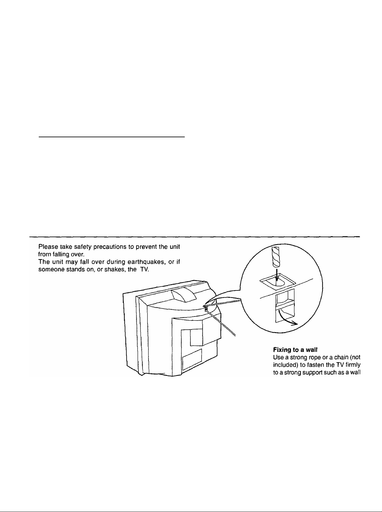
Safety Precaution
or pillar.
Page 7
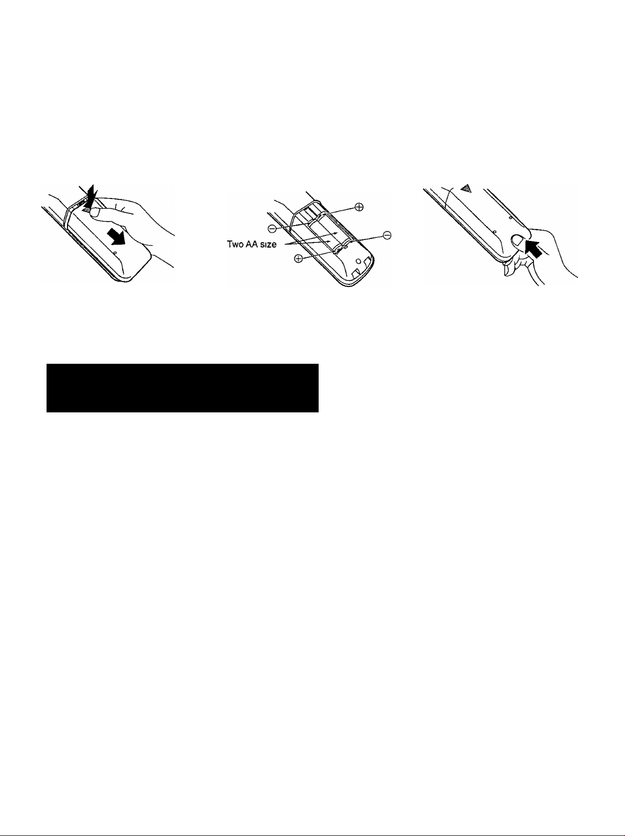
Remote Control Battery Installation
Requires two AA batteries
1 Turn the Transmitter face down
Remove top cover by pressing
down on marking and sliding cover
off in the direction indicated
Helpful Hint:
For frequent remote control users, replace old
batteries with Alkaline batteries for longer life
Install the batteries as shown in
the battery compartment (Polarity
+ or - must match the markings in
the compartment)
Installation
Replace the cover and slide in
reverse until the lock snaps
Note: In order to maximize the life of the batteries, the
lighted buttons on the Remote Control can be turned OFF
and ON by pressing R-TUNE and RECALL at the same
time.
A
Precaution on battery use
Incorrect installation can cause battery leakage and corrosion that will damage the remote control transmitter
Observe the following precautions:
1 Battenes should always be replaced as a pair Always use new batteries when replacing the old set
2 Do not combine a used battery with a new one
3 Do not mix battery types (example “Zinc Carbon” with “Alkaline”)
4 Do not attempt to charge, short-circuit, disassemble, heat or burn used batteries
5 Battery replacement is necessary when remote control acts sporadically or stops operating the TV set
Helpful Hint:
Whenever you remove the battenes, you may
need to reset the remote control infrared
codes We recommend that you record the code
on page 62, prior to setting up the remote
Page 8
Installation
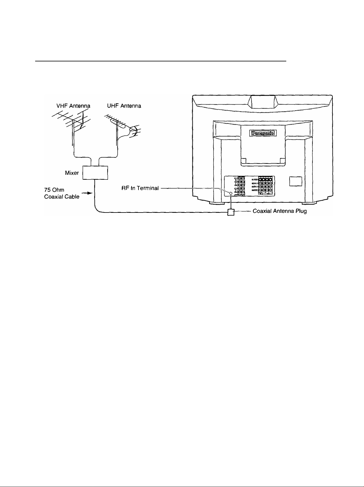
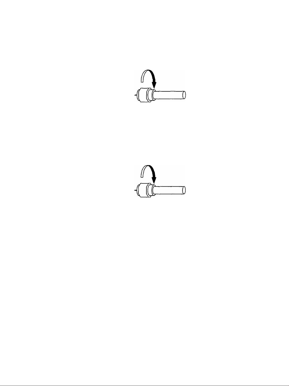
Connecting the Antenna Cable to the RF In Terminal
Antenna Connection - For proper reception of VHF/UHF channels, an external antenna is required. For best reception an
outdoor antenna is recommended. Antenna Mode must be set to TV.
8
Page 9
Installation
Antenna / Cable Connection
Incoming Cable From Home Antenna (75 Ohm)
VHF/UHF
on Back of Set
Incoming 75 Ohm Cable (From Cable Company)
Cable Connection - For reception of cable channels (01 - 125) connect the cable supplied by your local cable company
Antenna Mode must be set to CABLE (Refer to Antenna Mode section )
VHF/UHF
on Back of Set
Note;
Certain cable systems offset some channels to reduce interference or have Premium (scrambled) channels A cable
converter box is required for proper reception Check with your local Cable company for its compatibility requirements
Page 10
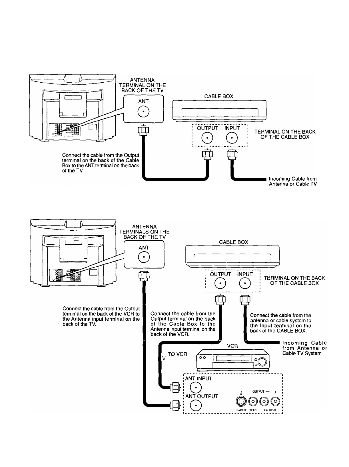
Installation
Antenna Connection (Cable Box, no VCR)
Use this configuration when connecting the TV to a cable TV system using a Cable Box.
System
Antenna Connection (Cable Box, and VCR)
Use this configuration when connecting the TV to a cable TV system using a Cable Box and VCR.
Note: When the antenna cable is connected to the TV antenna terminal via a cable box or VCR, set the TV channel to CH3
or CH4, cable. This does not apply when signal is input from VIDEO INPUT
10
Page 11
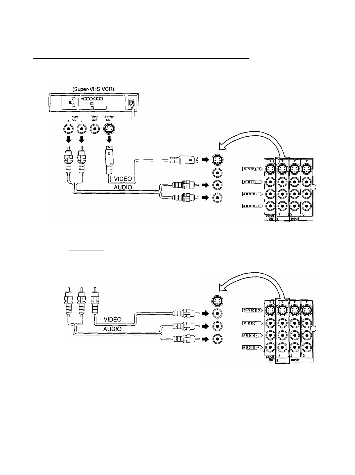
How to connect the “1, 2, 3, 4” input terminals
Connects VCRs and other peripheral equipment
Installation
(VHS VCR)
•oooooo
0|
“o
Au^O
OUT
m
m
I
VidaO
OUT
• )) ((•)] ((^
4 A ♦
Notes:
(1) When a monaural VCR is used, connect the monaural audio cable to the AUDIO-L (Left) terminal.
(2) Similar connections are available at the INPUT 1, 2, 3, 4 input terminals.
Input 4 is located on the front of the unit.
Select the desired VIDEO input position by pushing the TVA/IDEO button. (See page 27)
(3) When connecting video cables, priority is given to the S-Video cable when the S-Video input terminal and the video
input terminal are connected at the same time.
11
Page 12
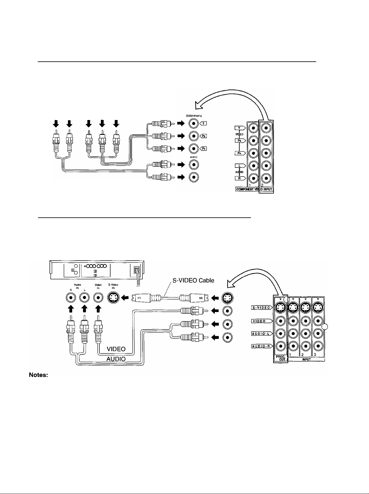
Installation
How to connect the COMPONENT VIDEO Input Terminals
DVD Player
Ajdkh
OUT
How to connect the AV Prog. Out Terminals
The “Prog. Out” Terminals output the same signals as main picture on the TV screen and sound from the speaker at that
time, e.g. TV programs or signals from INPUT 1,2, 3, 4 terminals.
OVDîY^^PkîOLTT
Pn Pe Y
________________
Recording Equipment
(VHS VCR)
(1) Never connect the VIDEO IN and Prog. OUT terminals to the same video recorder, as this could cause incorrect
operation.
(2) The monitor output emits the main picture normal video and audio signals.
(3) Even if the television is in picture-out-picture condition, Prog. OUT terminals output the same signals as main picture on
the screen and sound from speaker. Sub picture including strobe, still, channel search, etc. will not be output at the
PROG. OUT terminals.
(4) DVD signal (Y, Pb, Pr) is not output at the Prog. OUT terminals.
(5) COMPONENT VIDEO INPUT
In order to prevent colors from interfering, image signals are divided into three signals of brightness, red and blue
(green is created automatically from these three signals). Each signal is processed from its own circuit and combined
on the screen, creating a natural picture.
_
Page 13
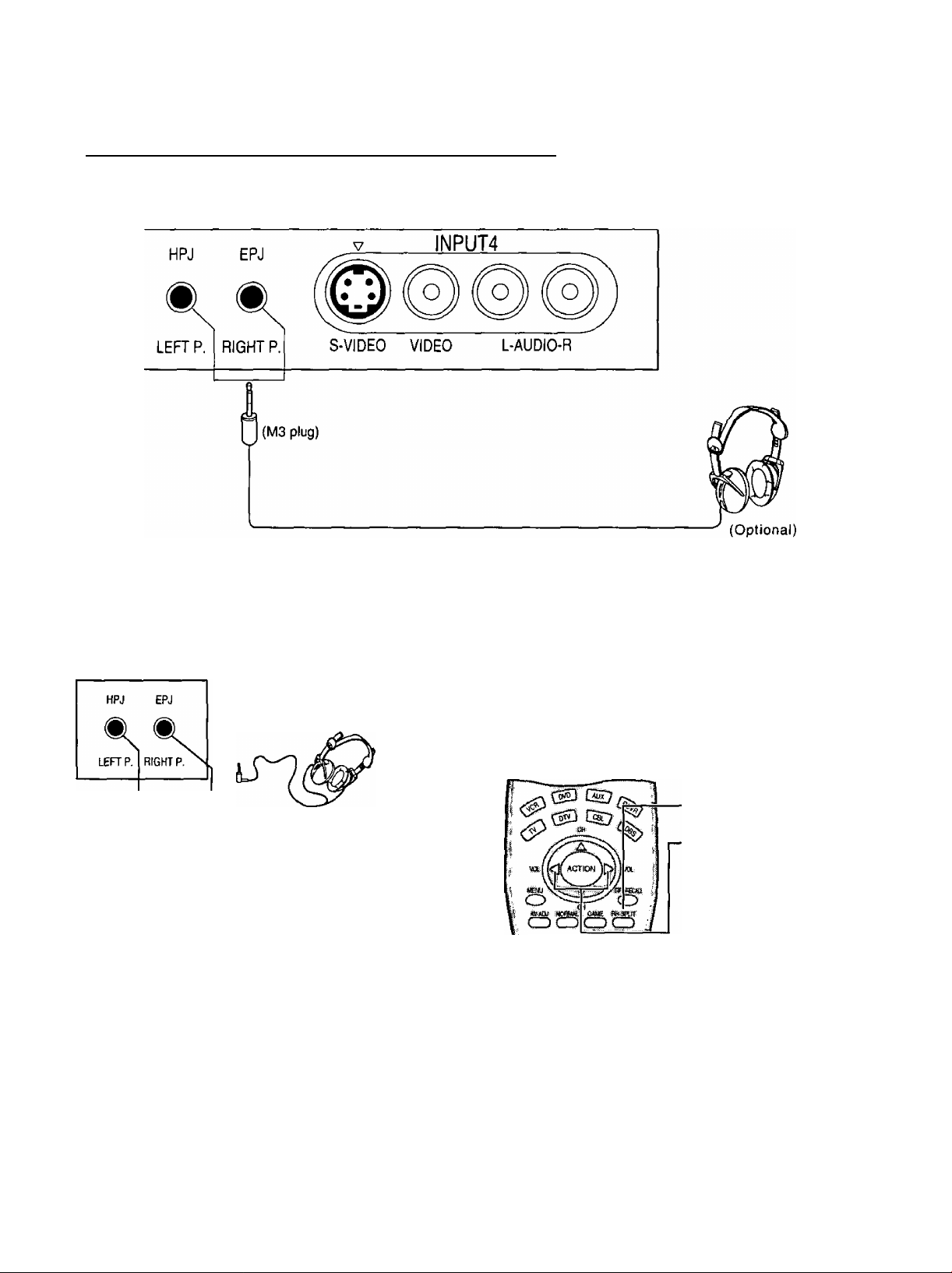
Connecting Headphones / Earphones
Connect headphones / earphones as follows.
Installation
You can listen to sound from each of the headphones Jacks as shown below.
Front jack
Sounds from
speakers are turned
off.
Speakers also
function.
M3 plug jack
Headphones (stereo) or
earphones (monaural)
• Volume and sound effects will
vary, depending on the
connected headphones or
earphones.
RIGHT P. (PICTURE)
• During single screen, volume adjustments can be made.
• During split screen, sound from the right screen is played
and its volume adjustments can be made.
1. Press the RH-SPLIT
button.
2. Immediately make
volume adjustments.
LEFT headphones plug:
When a LEF^ headphones plug is inserted into the LEFT headphones socket, all speakers will be automatically disconnected;
only the headphones will function.
Use Volume Up ► or Down ^ button to control volume level.
13
Page 14
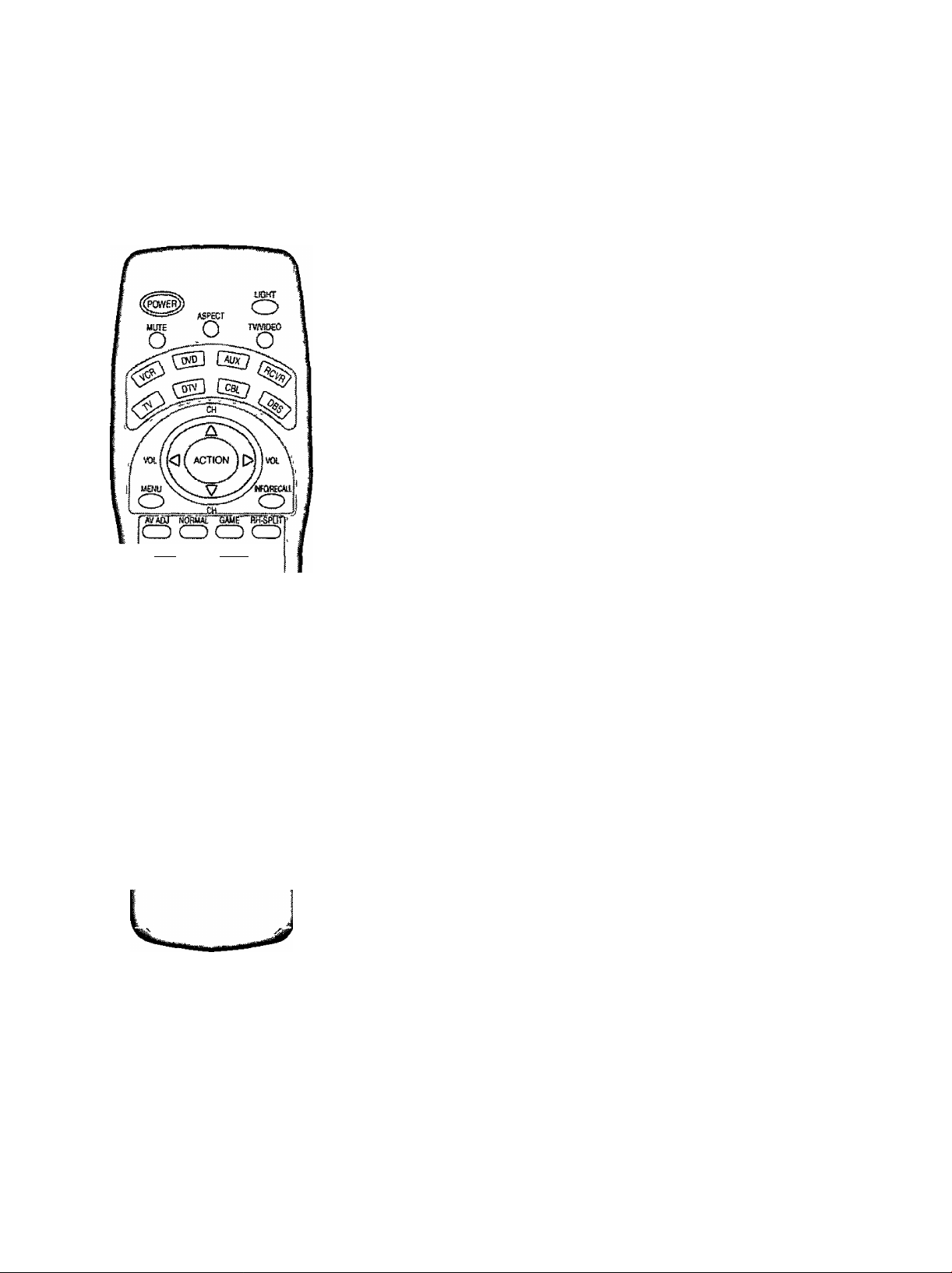
Illuminated Remote Control
Power button
Press to turn the TV ON or OFF {See page 17)
Note.
The TV’s power cord must first be plugged into the wall outlet and then turned on at the
POWER switch (standby mode)
MUTE button'
Push this button to mute the sound (See page 29)
Mode Selection buttons
Selects the operation mode for the remote control (See page 58)
Digital Video Disk Mode Selection for Remote Control
VCR Mode Selection for Remote Control
....
..............
.....................................
^1 Mode Selection for Remote Control
^ ^
TV Mode Selection for Remote Control
Digital TV Mode Selection for Remote Control -I
Operation of other Device
■- Cable TV Mode Selection for Remote Control
ru.-
..........................................................................
Receiver/Amplifier Mode Selection
Digital Broadcasting Satellite for
Remote Control
...
....... r
.............
—..........-
...........
...................m
............................
....................
disoass©
TV
VCR REW STOP
CABLE/DBS
DVD/LD/CD
RCVR
(S
—
— — — —
Skip Search REW
Srround -
Split search
CD
TV Split Freeze
VCR TVA/CR switch
CABLE/DBS
DVD/LD/CD Open/Close
RCVR Center -
—
Channel down
Channel down Channel down
Slow-/LD-side B
H
STOP PLAY Skip Search FF
— —
—
/Random
E
—
PLAY FF
Channel down Pause
Slow'/LD-side A
/Repeat
Center +
E)
Split ON/OFF
Surround +
: ©
Split Swap
Still/Pause
—
rtune R-TUNE button<
Switches to previously view
to channel or video mode
14
Page 15
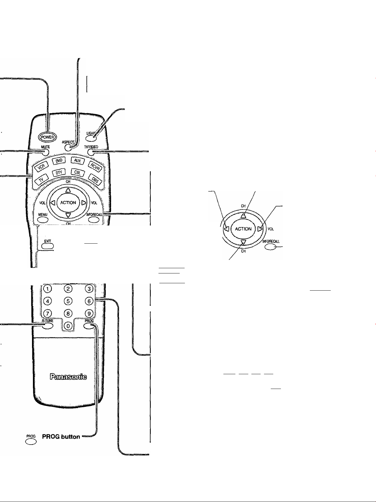
ASPECT button
Change of screen size {See page 22).
Location of Controls
CD CD CD CD
VCTREC
CE>
Puff
FREE2E
twvcfl vctasBs
<D CD CD ©
toPEKctosc - ..-
H H
CD
___
Panasonic AUTO
Guce
:SPUT
FF
sww
mk
JUST-
FULL
NORMAL-
ZOOM
Lights the remote control buttons.
The selected button blinks when lit.
TV/VIDEO button.
This input mode changes each time this button is pressed. (See page 27)
Reduces volume
Moves cursor to the
left during menu
mode,
Displays menu . vol[
Press the Menu \ \
button to display \ menu
the Menu screen,
iberni
ffjtiq PIC TI Ire ADj usT
il-k|pDSIllQU/SIZ£
I J> lAUDK? ACLKJST
Turning ON and OFF the remote
control illumination
Remote control illumination
^ can be turned ON OFF by
INFQRECAa pressing the INFO/RECALL
CD button while pressing the
R-TUNE button.
Changes to the next channel up
Moves cursor upward during menu mode.
Increase volume
Moves cursor to the
right during menu
mode.
The screen below
is displayed for 10
seconds
Changes to the next
channel down
Moves cursor downward
during menu mode.
[O
SAP
STANDARD
I
NORMALIZATION button
Each setting in the MENU screen
is reset to its standard values
(PICTURE, ADVANCE, AUDIO,
POSITION/SIZE)
AV ADJUSTMENT
button
AV-adjustments are
displayed.
(See page 35, 37)
AV-ADJ NORMAL GAME RH-SPLIT
CD) CD CZ) CD
EXfT
CD
Returns to normal
viewing from the
MENU screen.
Previous item in
MENU.
Direct program number
selection buttons
VCR Record button
GAME button
(See page 28)
VCR RECOGUIDE
CD
RH-SPLIT button
Operates the right
screen (See page
31).
GUIDE button
for DBS.
15
Page 16
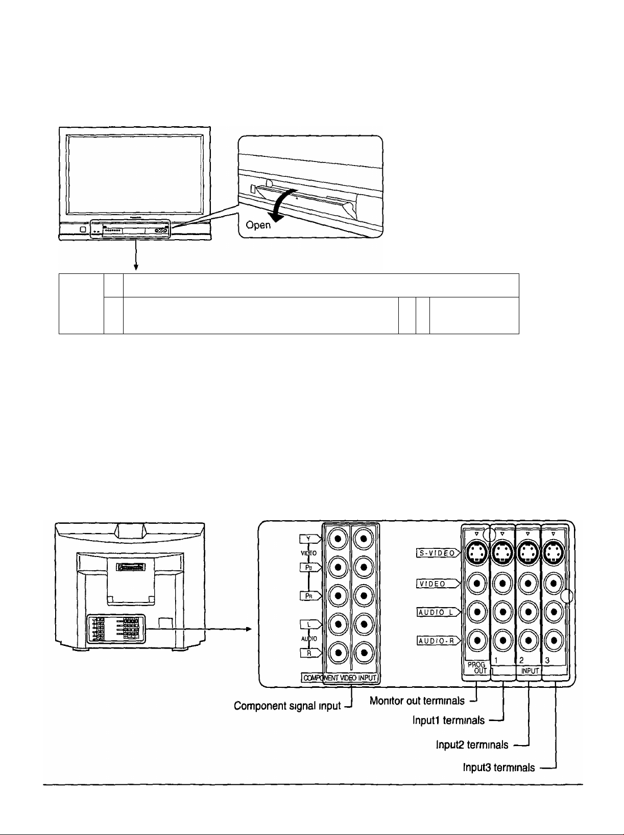
Location of Controls
Controls and Terminals on the TV
Press the ▲ mark on the center of
the front cover to open
1 1
JDDDODD 1 1 1
c
ME
Cp CD
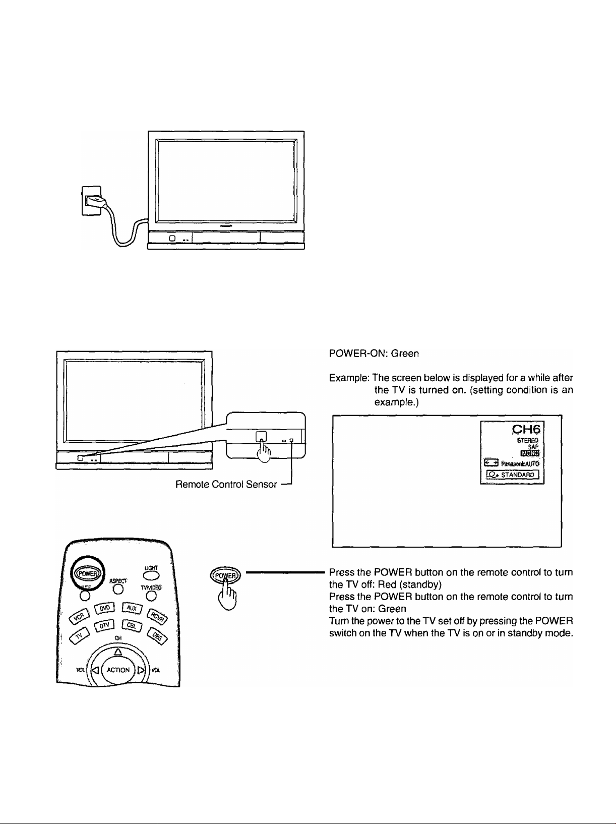
l— Remote Control Sensor
Power Indicator
The Power Indicator will light
« Power-OFF Indicator not illuminated (The unit will still consume some
power as long as the power cord is still inserted into the wall outlet)
»Stand-by CD Red
, Power-ON Green
AC CN7VV >«Pauuf» VlhUNNElA \ 1 ^
M M \ /
Program number selection buttons (see page 19,24)
Volume up(+) / down(-) buttons (see page 18, 24)
Input mode selection buttons (see page 27)
Action button (see page 19)
Menu button (see page 18)
Stereo headphone jack
“j
(©©©0)
IP
S-VltJEO WDEO LAUtKM
Input4 terminals
Video camera and TV game
cable terminal
Earphone jack
Cl
16
Page 17
Connecting the Plug to the Wall Outlet
Note:
Main plug types vary between countries. The power plug
shown at left may, therefore, not be the type fitted to
your set.
How to Turn the Power On
Push the POWER switch on the TV to turn the set on.
17
Page 18
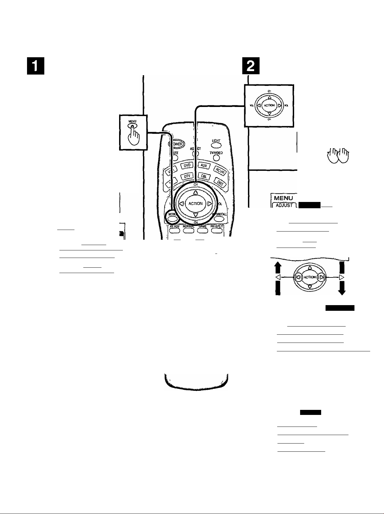
If the MENU button is pressed, the
MENU screen will be displayed
If the MENU button is pressed
once more while the menu screen
IS displayed, the MENU screen
will be cleared
The MENU button on the main
body can also be pressed to
display the MENU screen
Select MENU desired by pushing Right
“ ► ” button or Left “ ◄ ” button
The MENU button on the
mam body can also be
pressed to display the
MENU screen
O □ O 0 o □ □
MENU C1BKWVLK} iTUftTc TCHWWaA
MWU 4X)U)UEV
M£MU
IPMIPICTURE ADJUST"
)HR|pOSiTIOR^IZE ~
r^TAUpio ADJUST ~
□ □□□□□
________
PICTURE
AUDIO
EXIT VCSPEC GTOE
CD O CD
rtUTf rr
& ® B &
VCRtSS OVMiQ,
® ® cs> ®
I© © ®
Q © ©
PiK»
O IKO
USHseaite
SWAP
iJCUSTOM^
PICTURE
\mmm
m PICTURE ADJUST
lBB|POSiTION/SIZE
I Iauqio adjust
MENU
AUDIO
iTcusTOMll
^SET Opv
o
EE CHANNEL SEARCH 1
ifgr^SLEEP TIMER ~ ~ 0|
i 41aUDI0 MODE I
(jC2>) POWER SAVE STANDARD I
t I
<
-------
jklH «iTfON J M
---
[>
18
MENU
mssmi
fftOluNGUAGE
CUSTOM
tTSETuPl
irniPROGRAM channels'
ri'Hocii —
[^[closed caption
I VIDEO
Page 19
Flow Chart of Main menu
TO PICTURE
ADJUST menu
ETOTOREAOJ.
; ! PICTURE MENU
} PICTURE
;J BRIGHTNESS
)SHARPNESS
j COLOR TEhtP
;[ NORMAL r !
I AUTOiiiiil
;ilWMNCEPAOJ.i’OFFli^ONl
©
CD
_ pL
3 □ o o □ □
o c
MENU AC1
OJTV:VCE0 4VCLUMEP VCHAWEIA
The MENU button on the main
body can also be pressed to
display the MENU screen.
TO POSITION/
; POESnoiesizE
: (<CO
■ ......................................................
iVM GAIN
Iblack extension
ij WHITE CHAR CORR
ICOLOR TEMP CORR
;I NORMALIZE i:
m \
EM I
m
I
nj,
^ POSiTCN
SIZE
ffld:
TO AUDIO
ADJUST menu
iUtfSOAIXt
;i ÀUDIO MENU
Ibass
JTREBLE
:;j BALANCE
;! SURROUND
(CENTER SP
lAfB
; (SPEAKERS
i CfiSNSÈ'^
eSi
i NORMAL I
----------
^—!
E8ti—i
HfgFWSnCTil:
“tesHasH etili
®^roNl|
‘ A J
TO CHANNEL
SEARCH screen
TO SLEEP TIMER
adjust screen
i| SLEEP TIMER
TO AUDIO MODE
adjust screen
AUDIO MODE
mm
-----
TO LANGUAGE TO PROGRAM TO LOCK
selection screen CHANNELS adjust screen selection screen
MODE
AUTO PROGRAM
MANUAL PROGRAM
CH«iG£' -^tECT
CAPIR I
TO POWER SAVE
adjust screen
1 standard““"
TO CLOSED CAPTION TO VIDEO
selection screen
NO
HZ
adjust screen
19
Page 20
Automatically searches and adds receivable channels in the installed area and/or CATV signals to the program.
Channel tuning cannot be performed when the MAIN picture is not receiving a TV broadcast (tuning is not possible)
^ Press the MENU button to display the MENU screen and select SETUP
CH
Press to select PROGRAM CHANNEL
Press to display the PROGRAM CHANNEL
Press to select MODE
Press to select TV or CABLE
CH
Press to select AUTO PROGRAM
Press to display the confirmation screen
MENÜ
G0ST0MÌ! PsÈrD'p]j|
I
fftÖtLÄNGUAG?
I
( |r^l^OGRAM~CHANNELS[
i a [LOCK
ll£SICI-OSED CAPTION
riiyiDEo : z:
PAGE^
Pi^AM CHANNElS
MODE
i
AUTO PROGRAM
MAN^UAL PiROGRAM |
CHANGE^
AUTO PROGRAM
•AUTO PROGRMT?
fVESI NO
^sascr
CHANGE
Press to select YES
AUTO Pf^3<^AM
!t> 'AUTO PBOGRAW
.
Press to run AUTO PROGRAM
Channels will automatically advance until all channels have been scanned Channel numbers with a video
signal present will turn blue Which indicates it has been stored in the Channel Scan Memory
5 Press the MENU button to exit the set up menu
Notes*
• When buttons are pressed with AUTO PROGRAM running, the TV set will return to normal viewing {Channel
searched up to this point are added )
• After AUTO PROGRAM is finished, the lowest channel number added will be received
• When there are no receivable channels, channel 69 is displayed (channel 125 for cable TV)
20
H
Page 21
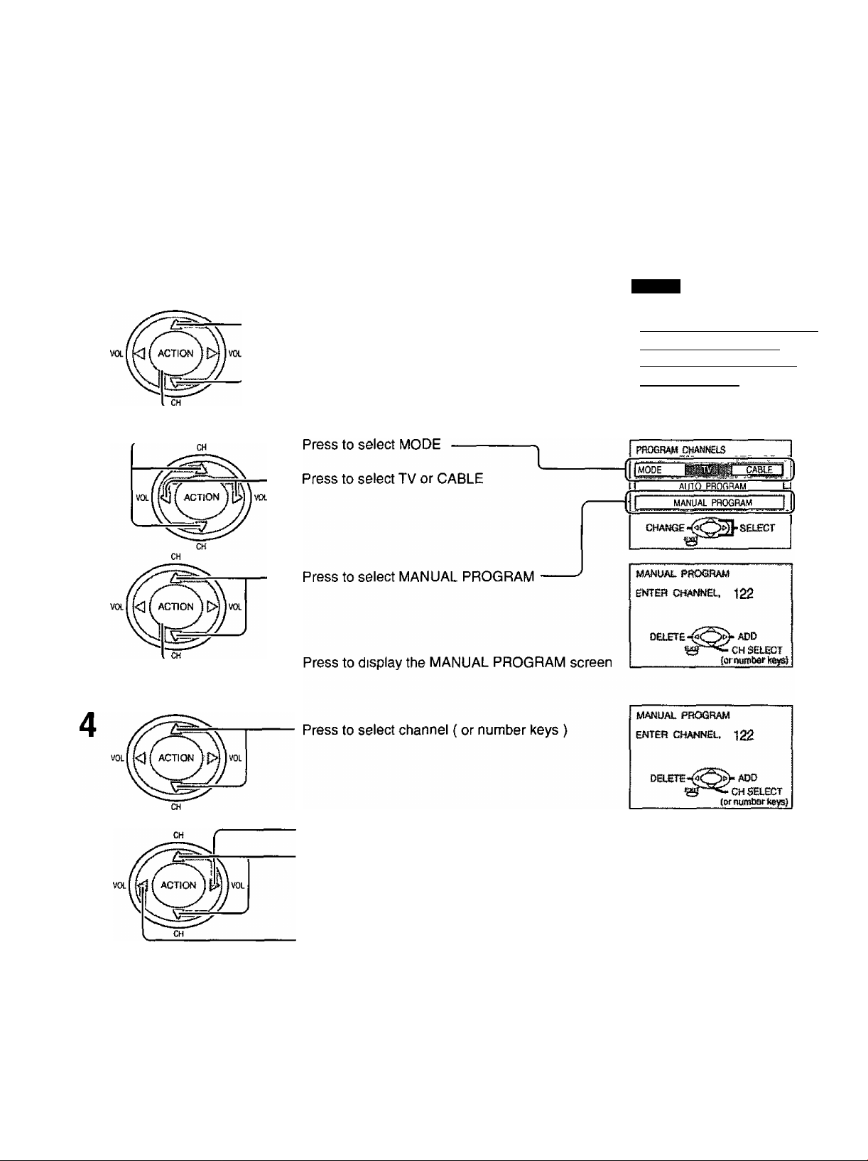
Use this setting when changing setting of receiving channels or changing the channel display.
Turn the TV on and select the broadcast channel Follow the steps on the previous page to display the PROGRAM
CHANNEL screen
This PROGRAM CHANNEL screen can be displayed when the MAIN picture is a TV broadcast
Selecting the PROGRAM CHANNELS menu.
Press the MENU button to display the MENU screen and select SETUP
CH
1
Press to select PROGRAM CHANNELS
Press to display the PROGRAM CHANNEL
MENU
I&QIlanguage
jl l|PRORRAM CHANNELS |
I fl [LOCK T
(Ш|С105ЕР CAPTION I
iZViVIDEoZZ " I
PAGE *^«^saECT
Adding or deleting channels
CH
Press to add channels to memory ( blue )
Press to select channel
Press to delete channels from memory ( yellow )
Repeat steps 4 and 5 to continue adding or deleting channels
^ Press the MENU button to exit the set up menu
21
Page 22
The color monitor will allow you to enjoy viewing the picture at its maximum size, including wide screen cinema format
picture
EXiT VCflIiEC GUB)£
CD O CD
REW PU,
------
d] S
S«K
------------
i£iL
FREEZE SWAP
TWW31 TCWBJ CMW-a B«KE
CD ® CD ®
ASPECT
Notes'
(1) For a 480p signal input during component input signal mode, the
(2) When a IO8O1 signal is being received, the mode is set to FULL,
(3) During split screen, modes will change as follows
ASPECT button
The aspect mode changes each time the ASPECT button is
pressed
- Panasonic AUTO —► NORMAL —► JUST —
FULL ZOOM
mode switches between ZOOM and FULL only
and aspect switching is not possible
FULL
NORMAL
Pout P
n
© © ©
R-TtBiE ■?) _ (
O ®I o
22
Page 23

ASPECT Controls
Mode
Panasonic
AUTO
NORMAL
Picture Explanation
The display wilt automatically become enlarged
(depending on the picture source), allowing you to view
the picture at its maximum size.
Note:
Image is expanded
Changes in accordance
with the Panasonic
^ AUTO mode setting
(Refer to page 22)
(1) If Panasonic Auto mode is selected, the image may
change size suddenly, according to program
material.
(2) There may be a slight delay for the screen size to
adjust. If a 480p or 1080i signal is input during
component input signal mode, the controls will not
operate.
NORMAL will display a 4:3 picture at its standard 4:3
size.
ZOOM mode magnifies the central section of the picture.
ZOOM
-16-
FULL
JUST
Notes:
(1) The S-VIDEO terminal on this set can detect specially encoded signals that are compatible with a wide screen monitor.
When a full image from the S-VIDEO terminal of specially encoded video is detected by the set, the screen size is
automatically set to FULL mode.
(2) The screen size also changes if ID-1 is detected.
(3) The screen size will also change if Si detection has been set.
3 «f
3 ^
T
oV_ Jo
FULL will display the picture at its maximum size but
with sight elongation.
JUST mode will display a 4:3 picture at maximum size
but with aspect correction applied to the center of the
screen so that elongation is only apparent at the left
and right edges of the screen. The size of the picture
will depend on the original signal.
23
Page 24

1 Press to turn the TV on {See page 17).
Press to operate the TV set with the remote
control.
Notes:
• The channel number and volume level are set even after the TV is
turned off.
• Power consumption and howling of sound can be reduced if the volume
level is lowered.
* •
Press to select the desired
channel.
Select the desired volume level.
24
Page 25

Incoming Cable from Antenna
or Cable TV System
When the antenna cable is connected to the
TV antenna terminal via a cable box or VCR,
set the TV channel to CHS or CH4
This does not apply when signal is input from
I -I
CABLE BOX
VIDEO INPUT.
Confirming
Confirm that registration with cable TV and connection of equipment
are completed Turn the cable TV tuner and select the desired volume
level
1
Press while pointing the remote control towards
the cable TV tuner
Note*
The remote control code number is set for
Panasonic products
When peripheral equipment does not operate,
reset code (See page 59 and 60)
0 Operate the cable TV tuner and select the desired volume level
25
Page 26

When a SEARCH / STOP button is pressed during single screen
The sound from the left screen will be heard
2
4
from both [LEFT P ] and [RIGHT P 1 screen
ram
When a channel button is pressed during channel search
• Number keys
Example When 8 is pressed, channel 8 is displayed in single screen
• Channel up and down keys
When A or ▼ button is pressed, the next channel up or down is displayed in single screen
When a SEARCH / STOP button is pressed during single screen
When a channel button is pressed during channel search.
The selected channel will be displayed on the right screen (pause is deactivated)
6
The sound from the left screen will be heard
2
4
6
from both [LEFT P ] and [RIGHT P ] screen
jacks {both earphones and headphones)
Channel search:
Channel search displays each channel, in order, as a paused image Channels are displayed from the left top to the right
bottom in order When it reaches the right bottom, the next channel is displayed at the left, overwriting the previously
displayed channel
Notes
• To end channel search, press ^ SEARCH STOP
• Channel search can be activated from the MENU screen
26
Page 27

VCR
Laser Disk Player
DVD player
This equipment can also be
connected to the rear
terminals. See Connections
for details.
Turning the power on and switching input modes
^ Turn the TV on.
r=\
■ , ^ ^ ^ , 'trmm
o O
CD CD CD CD
aiT vcpflEC
a o CD
Q S B ®
FREES SftWP
tfcftsas Otf№ Fwsf
CD CD ® CE>
trtUNE“
....
T ^ ['"“' PROG
O j®|: o
TV/VIDEO
Note:
When the remote control is unavailable, input modes can also be switched
on the TV set using the TV/VlDEO button.
2 Operate the connected equipment.
The input mode changes each time this button is
pressed. (See page 46 and 47)
TV
When playing
a video
• When playing J
a DVD
• When playing
a laser disc
• When playing from *
a video camera
(No input mode is
displayed for terminals with no equipment connected.)
..........
.....................
......
......
- VIDEO 1
-j VIDEO 2
H VIDEO 3
H VIDEO 4
COMPONENT 2
COMPONENT 1
IJ^DDgBSCife
27
Page 28

To audio output
Turning on the TV and switching to game modes
^ Turn on the TV
GAME
Press the GAME button to switch to game mode
Displays the lapsed time
Lapsed time is displayed for 5 seconds
every 30 minutes
Be sure to rest your eyes every 30
minutes
GAME GAME GAME
28
TV screen
2 When finished, press the GAME button again {Turn off the
game mode by switching input modes or changing the
channel)
Notes.
• Video input mode can be changed when the GAME button is pressed
• Game mode is maintained when power to the TV is turned off
• When game mode is selected Picture will be set to PICTURE MENU
(GAME), and sound will be set to SOUND MENU (GAME)
factory default setting
Item
Picture menu
Audio menu Game
Surround ON
Screen mode FULL
Picture and sound can be set as desired (See page 34 and 36 )
The lapsed time display stops after 90
minutes
Setting
Game
Page 29

Recall (On-screen display)
INFORECALi
Press this button to display channel number, off-timer
remaining time, screen modes, and other settings For
approximately 10 seconds, only the channel number
remains.
The channel number remains, but other information
disappears after a specified period Press this button again
to delete channel number display
Full Information
CH6
^160
ÌQ> standardI
channel number or Video
Input Selected
multiplex sound
ASPECT mode
power save mode
off-timer status
{See page 49)
Channel number
CH6
The INFO/RECALL button switches the display in the following order
-► Full Information —► Channel —► No display
---
1
Mute
Useful when answering the phone or receiving unexpected visitors
MLTTE
Press this button to mute the sound Press again to reactivate
sound Sound is also reactivated when power is turned off
or volume level is changed
29
Page 30

Split screen enables you to search other channels on the right screen or check video recording status
Notes.
• Sound from the left screen is output from the speakers on the TV set
(EPJ) Sound from the right screen is output from the right earphone
jack output on the front of the TV set (see page 13)
• When the screen is split, signals of the left screen are output from the
rear monitor output terminal
• The left and right screen are processed by individual circuits and,
therefore, may have slight variation in sound and image quality
• Split screen returns to single screen when the TV is turned off
30
Freezing pictures
Press during single screen to
freeze
The screen is split and the
freeze image is displayed on
the right and the broadcast
channel continues on the left
FREEZE
wwR Press to recover
Page 31

Changing the channel of the right screen
during SPLIT SCREEN FULL, SPLIT SCREEN
NORMAL, and PoutP.
split screen
RH-SPLrr
1
Viewing videos
TV/VIDEO
Press to operate right screen.
CH10
While 0 is displayed on the
screen, press to switch modes.
Example:
S^rACTIVF'l CMS-
While 0 is displayed on the
screen, press to switch modes.
Change to channel 5.
CHIO
S-
ùtìi
• The channels for the left screen can be changed in
the same way as when the screen is single.
Notes:
• Use earphones to listen to sound of the right screen during SPLIT SCREEN FULL, SPLIT SCREEN NORMAL, and
PoutP
• The right and left screens cannot display the same picture at the same time.
• Use the right screen when playing video games on a split screen (to avoid distortion of images).
Screen mode names:
CHIO CH3
SPLIT SCREEN FULL SPLIT SCREEN NORMAL
CHID CH3
CHIO
PoutP
"TR3
31
Page 32

Adjusting screen
1
ASPECT
MENU
Press to select the screen mode to
adjust
Press to display the MENU screen
Press to select
ADJUST menu
Press to select POSITION/SIZE and
press ACTION
iCUS TOM Lift
"ÀcSOsTtì
IHgrURE
I [jfUlPiC TUBE "adjust [
IWIposìtioh iizE ~
AUDIO
[Z |auDìo adjust n
fvmiùmim
mm.
s№
® CD ®
(D
...
Notes:
• This TV IS equipped with various screen modes If a screen mode with
a different aspect from the broadcast program is selected, image will
appear differently Select the proper screen mode with this in mind
o Be careful when using this TV for commercial purposes or for public
use, such as in cafes and hotels Shrinking and enlarging images by
using screen mode switching function {zoom, etc ) may violate copyright
laws
• Images displayed on a wide screen TV will be cut off or distorted at the
edges, when viewing normal aspect images of 4 3 in ZOOM, JUST or
FULL mode Display in NORMAL mode to view the original image
intended by the producer
• For 1080i and 480p input images, screen position and size cannot be
adjusted
• The adjusted setting will be kept even when the TV is turned off
• The signals output from the monitor output terminal on the back of the
TV are not affected when the screen size and position are adjusted
© © ®
o
©
32
Page 33

Adjusting screen position and size
Switching screen width
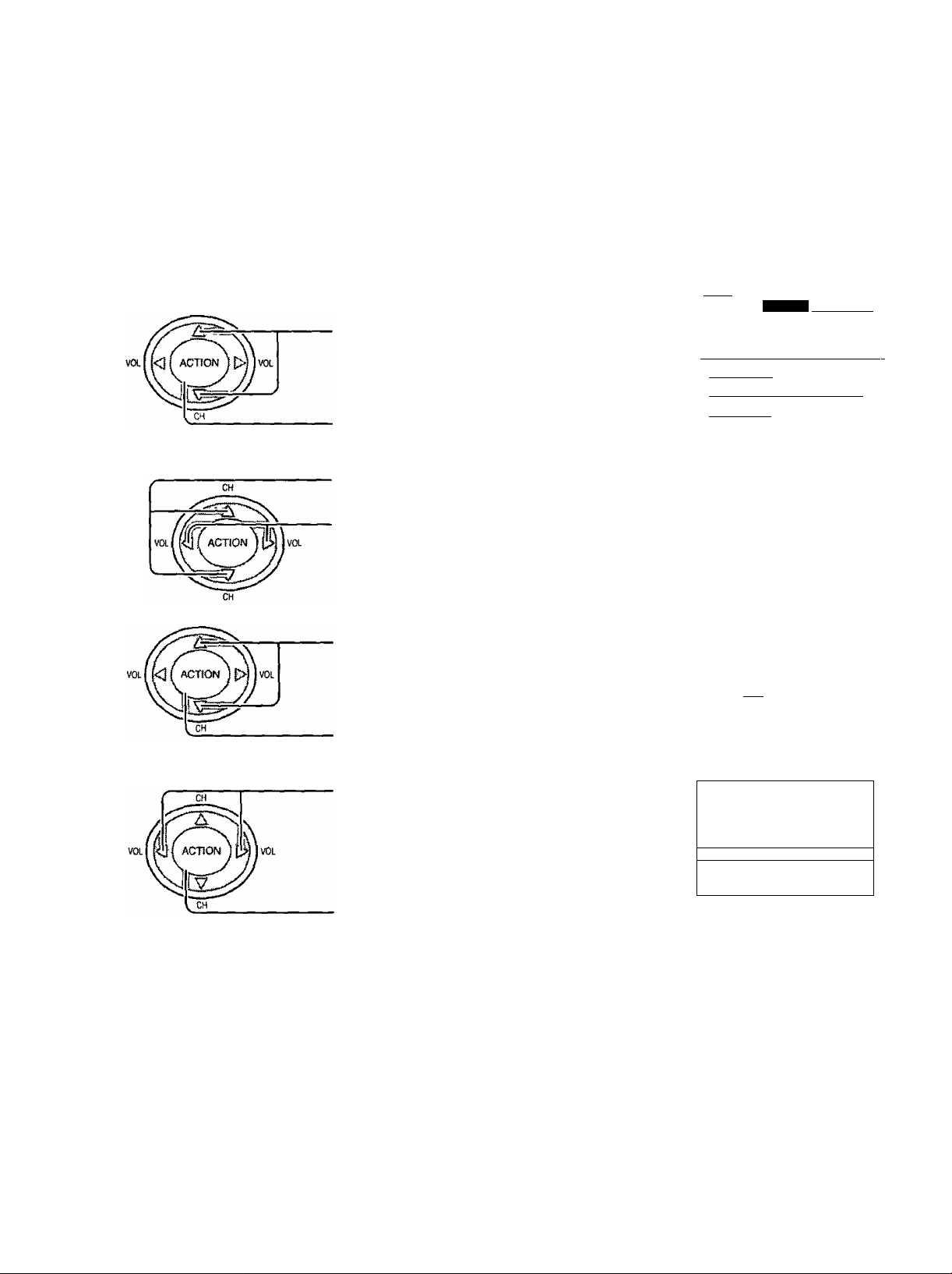
During NORMAL mode, if noise appears on the ends of the image in SIZE 1, switch to SIZE 2
CH /
-----------
A
Press to narrow (SIZE 2)
VOLl
^
----------------------
During JUST mode, if noise appears on the ends of the image in SIZE 1, switch to SIZE 2
Press to widen (SIZE 1)
Press to enlarge image
horizontally (SIZE 2)
Press to shrink image
horizontally (SIZE 1)
^ (SIZE1) ^ ^ (SIZE 2) ^
• To return to standard -* ACTION
• To end adjustments ^ MENU
Changing vertical size
During ZOOM modes
Press to enlarge image
vertically (max 15)
(SIZE 2)
(EXIT)
Press to shrink image
vertically (min 1)
Displaying images cut off from the screen
For ZOOM and JUST modes
Press to move image upwards
Press to move image
downwards
[
• To return to standard
• To end adjustments -
• To return to standard
• To end adjustments "
=2^
ACTION
MENU
(EXIT)
ACTION
MENU
(EXIT)
33
Page 34

^ Press the MENU button to display the MENU screen and select ADJUST
Select AUDIO ADJUST of ADJUST fronn the MENU screen
CH
Press to select AUDIO ADJUST
Press to display AUDIO ADJUST screen
Press to select the menu to adjust each item
Select the desired level by listening to the sound
MKNH I
ADJUSTi'GUSTOMi
PICTURE
itnilPlCTURE ADJUST
[mi POSIT lON/SIZE
n I rrvir>
J>IAUP 10 ADJUST
Enables speakers to produce
the best quality sound
{Normally turned on)
AUTO
I STANDARD | Emits the original sound
DYNAMIC 1 Gives contrast to sound
MUSIC 1 ~l For programs consisting
T high sounds (around 4 kHz)
I MUSIC 2 1 Enhances high sounds even
When GAME is selected for the picture,
sound setting also changes to GAME
During GAME mode, sound mode cannot
be changed in this menu
To reset to standard setting,
select NORMALIZE with the up a and down ▼ buttons and press ACTION
To adjust settings individually, press the AV ADJUST button to select the desired
menu and adjust using the left ◄ and ► right buttons
Automatically adjusts quiet
sound and loud sound for
ease of listening
mainly of music Enhances
more (Recommended for
those who have slight
hearing deficiencies)
To end adjustments
34
MENU
C3
Press MENU button
Page 35

Turning the center speaker ON and OFF to enhance the mood
During AUDIO ADJUST menu
Press to select CENTER SP
Press to select switch
Audio Adjustments
AUDIO ADJUST
NORMAL !
1 audio menu
i
ON • Sound given off from the center is enhanced and stability is increased
OFF • Use when certain scenes are hard to hear or to enhance and increase stability
Turning the speaker sound ON and OFF
SPEAKERS OFF
Turns off the speaker sound
Notes
• Sound signals are output from the rear AUDIO OUT terminal
• When volume is adjusted or the mute button is pressed from the remote control,
a message will be displayed
• Sound signals from the headphone and earphone jacks are as follows
HPJ OFF
EPJ ON
SPEAKERS ON
Speaker sound is normal
• To end adjustments
MENU
O
I speakers'
[speakers
onI
[ iSURROUND
! [center SP
....
audio adjust
rÀUDlO MENU
[f^B
DeJiiil i
j NORMAL " ~|
.Aidri
•ttgigg'ON f
onIbI
[
By pressing the AV-ADJ button on the remote control, PICTURE ADJUST and AUDIO ADJUST can be directly adjusted
instead of starting from the MAIN menu
AVADg
C3-
The selected menu will change each time the AV-ADJ button is
pressed {press until the desired menu is displayed)
Adjust using the left 4 or right ► button
r
I PICTURE
ÌBRIOHtTjE^
IcaoR
IriW
¡SHARPNESS
[CaOR TENiP ^ I NORMAL I
[bass
fSAlANCi"
[surround OFF
,
__________i___
¡CENTER $P
3
[a^~
a
;W
■
»Mil ON i
35
Page 36

^ Press the MENU button to display the MENU screen and select ADJUST
[ ADJUSTljflGUSTOMi
mmm
VOL
NORMAL IS displayed at default
PICnjRE ADJ.
NORMAL
PICTURE MENU
PICTURE
BRIGHTNESS
COLOR
TINT
SHARPNESS
COLOR TEMP
ADVANCED ADJ
Press to select to
PICTURE ADJUST
Press to display the
PICTURE ADJUST screen
Press to select the menu to adjust
Select the desired level by looking at the picture
behind the menu
Press the left ◄ or right ► button to switch between modes
I AUTO ------------------------- STANDARD
DYNAMIC CINEMA
I auto" I Auto
j Adjusts brightness, depending on
▼ surrounding light, for easier viewing
I STANDARD I STANDARD
^ Displays unaltered image
I CINEMA t CINEMA
^ Ideal for movies
I DYNAf^ □ DYNAMIC
Displays a clear screen with
contrast of light and dark
irmilPICTUFIE adjust
imiPOSmONisIZE
AUDIO
1 Iaudio adjust
PtCTUREADJ
! NORMAL I
1 PICTURE MENU
1 PICTURE
! BRIGHTNESS
(color
Itint
!SHARPNESS
(color temp ■ NO^MA! ||
IaDVANCED ADJ
,,Pj—
..«■ L --a. 'I
Bli—HP 1
nr
-A -
■ OFF ON ■
-I
3
36
Adjusts picture in more detail
(see page 38)
During GAME mode, picture mode cannot be
changed in this menu
Press the left ◄ or right ► button to switch
between modes
NORMAL-
COOL WARM
n
Page 37

Picture Adjustments
ADVANCED ADJ
This function IS available when
STANDARD or CINEMA mode is
selected for the PICTURE MENU
ADVANCED ADJ ON
Enables fine picture adjustment at
a professional level (see next page)
ADVANCED ADJ OFF
Displays images with the selected
setting of the PICTURE MENU
• To adjust each item,
• To reset to standard setting,
• To return to normal viewing
CH
«L| J< if ACTKW H
MENU
o-
Press the up A and down T button and make adjustments
using the left ◄ and ► right buttons
if IvOL
Select NORMALIZE with the up ^ and down y buttons
Press ACTION
Press MENU button
Note:
There is little change when PICTURE is increased with a bright picture or reduced with a dark picture
37
Page 38

Picture Adjustments
Press left ◄ or right ► to turn ON, and a ► mark is displayed
Press down ▼ to display the ADVANCED ADJUST screen
ADVANCED PICTURE ADJUST
Dunng STANDARD or CINEMA mode, ADVANCED ADJUST setting is possible
Press to select menu
Press to adjust
MENU
• To return to normal viewing
• To return to PICTURE ADJUST menu
• To return to standard
C3
CH
CH
Press MENU button
Press up from VM GAIN, or press down
from COLOR TEMP CORR
Select NORMALIZE with the up ▲ and
down T buttons
ADVANCED ADJUST
j NORMALIZE
VM GAIN
BLACK EXTENSION
WHITE CHAR CORR
COLOR TEMP CORR
ADJUST-^
QüJ'
Wmi?
>)f-SELECT
w
Iiilìitwffll.l»,
Item
Content
VM GAIN Adjusts the emphasis for the Vertical contours
BLACK EXTENSION
Adjusts the dark shades of the image in
gradation
WHITE CHAR CORR Emphasizes the whiteness of parts such as
white characters
COLOR TEMP CORR Fine adjustments of color temperature
selected for each PICTURE MENU mode
38
Press ACTION
Adjustable range
0 (no adjustments) - 15 (max adjustment)
-7 (low color temperature) - 7 (high color temperature)
<reddish color> <bluish color>
Page 39

When playing special images such as three dimensional video disks on video disk players or game software on video
game players, use GAME mode Use TV mode for normal viewing
Selecting VIDEO menu
Press the MENU button to display the MENU screen and select SETUP
CH
Press to select VIDEO
Press to display the VIDEO screen
Switching to SCAN MODE.
Press to select SCAN MODE
MENU
ífADlíÜSfniTíeüSTG)w)S rmiip'
IftOlUNGUAGT
IrifpROGRAM CHANNELS j
fliLOCK
I [c^l CLOSED CAPTION
IrilVIDEoZ. ■_
PAGE SELECT
Press to select TV or GAME
MENU
O
Press to exit menu
Notes.
• The VIDEO set up screen is made up of 4 pages
Use the up A and down ▼ buttons to change pages
39
Page 40

This receiver has a built in decoder that provides a visual depiction of the audio portion of a
television program in the form of written words across the screen (white or colored letters
on a black background). It allows the viewer to read the dialogue of a television program or
other information.
Press the MENU button to display the MENU screen and select SETUP
1
CH
Press to select CLOSED CAPTION
Press to display the CLOSED CAPTION
screen
led On Mute
Activates the On-Screen Closed Caption feature, when the MUTE button on the
Remote Control is pressed To deactivate, press the MUTE button again
Note-
This feature functions when the Closed Caption Mode is in the “OFF” position
The program being viewed must be broadcast with Closed Caption
Press to select ON MUTE
Press to select from the following
MENU
TsetUF'
jftOlLANGUAGÈ“
o PROgHm CHAWELS |
i
j[cc]|CLOSED CAPTION
T’Jivm
figgi ON MUTE
NO(OFF) Cl ^ C2 C3 C4
r
Notes
• Recommended menu Set Up for Closed Caption when using Mute Button
CC ON MUTE Cl
CC MODE OFF
• The setting for CC ON MUTE is valid only when the CC MODE is OFF, CC MODE set to ON will override CC ON
MUTE
This menu cannot be selected when the MAIN picture is displaying a COMPONENT VIDEO INPUT of 480i or more
• When aspect is ZOOM, Closed Caption cannot be used
n
40
Page 41

Closed Captions
3 ICClMode
Activates the On-Screen Closed Caption feature When activated this feature will remain on until OFF is
selected in this menu
• CAPTION OFF
• CAPTION Cl -
• CAPTION C2 -
• TEXT T1 '
• TEXT T2 -
• CAPTION C3 -
• CAPTION C4 -
• TEXT T3 -
• TEXT T4 -
Press to select CC MODE
Press to select from the following
I Eg] mode“
OFF Cl ^ C2 T1 ^ T2C3 ^ C4T3 T4
c
-Recommended mode when Closed Caption is not being used
For video related information that can be displayed (up to 4 lines of script strategically placed on
the television screen so that it does not obstruct relevant parts of the picture)
Another mode used for video related information
Blanks out a large portion of the picture on the television screen, and displays program guide or
any other information currently being transmitted
Another mode which displays information and blanks out a large portion of the picture on the
television screen
Another mode used for video related information
Another mode used for video related information
Another mode which displays information and blanks out a large portion of the picture on the
television screen
Another mode which displays information and blanks out a large portion of the picture on the
television screen
CLOSED CWTION
j Eg ON MUTE
lEg MODE
CHAHSE'^
n
• To end adjustments
MENU
O'
Press MENU button
41
Page 42

In the United States and Canada, the V-CHIP consists of two rating systems, which are MPAA
(MOTION PICTURE) and TV PARENTAL GUIDELINES. Its function is to block programs by
the rating data in the XDS data packets sent from broadcasting stations. The user can select
which rating programs should be blocked by using the LOCK MENU options.
Press the MENU button to display the MENU screen and select SETUP
tttire O vmsQ
n M n
CDCDCDCD
v^c ajiPE i
S
o ® B
FREEZE SWAP
iwvw vwiBK iMMsa p«JSE
C£) ® ® <©
.........
®
0
O
@
©
©
e> CD
©
©
0
n
f' SET UP
the LOCK screen
Input code
Enter any 4-digit number as a password
These numbers will be needed when
deactivating the LOCK function
CHANGE CODE
MENU
PAO3ÖS«IiC;üSn‘0M:S
jft0|l-ANGUAGE
iiiniPROGRAM CHANNELS
CffEa
|tcc1|CL0SED CAPTION
LllyjDEC 1. D
LOCK
*\ CHANGE~S ETTING
TV PARENTAL STATUS
______
ii OFF
CHANGE SETTING
Note:
Use a code that is easy to remember or record it in a safe place
2 Selecting broadcasts to lock
42
{?6iiigBeDifis
VOL
Press to select CHANGE SETTING (the
menu following MOTION PICT STATUS)
Press to display the MOTION PICTURE
RATING screen
LOCK
MOTION PICT STATUS
TV PARENTAL STATUS
U OFF ' Hfc«
CHANGE SETTING
J3E
CHANGE SETTING |
WOTfOK PICTURE RATINÖ
VIEW NR PROGRAMS? |
NO RATING "^CD'ii’RA'nNG
P ~NO
i
ds;
■SELECT
Page 43

O
Lock Feature
CH
R Restncted
NC17 No one under 17 is admitted
X Pornography
EXIT
Press to return to LOCK screen
4 Setting MOTION PICT STATUS
Locking and unlocking the ratings selected above
Press to select MOTION PICT STATUS
Press to select ON or OFF
ON The broadcasts selected in the MOTION PICTURE RATING menu
cannot be viewed
OFF LOCK IS deactivated and any broadcast, regardless of the setting
for MOTION PICTURE RATING, can be viewed
MENU
O
Press to set
MOTION PICT STATUS
I3E
CHANGE SETTli^
TV PARENTAL STATUS
'HI CHANGE SErriNG |
CHANGE CODE
•SELECT
MOTION PICT STATUS
ON
43
Page 44

Lock Feature
TV PARENTAL STATUS
Press to select TV PARENTAL STATUS.
Press to select ON or OFF.
Changing setting
CH
screen.
Setting the TV PARENTAL PROGRAMS screen
VIEW NR PROGRAMS?
NO : The broadcasts selected in the MOTION PICTURE RATING menu cannot be viewed.
YES: LOCK is deactivated and any broadcast, regardless of the setting for MOTION PICTURE RATING,
can be viewed.
SETTING
BASIC: The up ▲ and down ▼ buttons change the selected title.
DETAILED: The cursor selecting the title can be moved to select options displayed on the right. The
down ▼ button moves the cursor to the right if options are available. The up ▲ button
moves the cursor to the left and if there are no options to the left, the cursor will move up.
LOCK
MOTION PICT. STATUS
TV parental STATUS
i OPF
CHANGE SETTING L
m OFF
PAUËMTAt mm
i TV-V7 i i F? I
I TV^a : J
[ mr^nnnn
I TV-14 1 t v . IL S II . L 11 D I
['TO^AI nrirRHITn
RATING-Ç)<
)^RAT)NG
‘SiïgCli
44
Page 45

Lock Feature
Locking and unlocking
• When a title field is selected, all ratings below this rating are selected.
• When options within an option field are selected, ratings below this rating within the same field are selected.
• Ratings displayed in green are unlocked and those displayed in red are blocked programs.
1. Ratings for children: These ratings are divided into ranks as follows.
2. Ratings for teenagers: These ratings are the same as the matrix system. This system is described in the
diagram below.
Ratings for all ages are on top and ratings for adults are on the bottom.
..
TV -G I
TV -P G I
TV -1 4 I
TV-MA i
m rsn
l V 1
[ V 1
1 V 1
1 SI
1 SI
1 S‘"l 1 L 1
1 L 1
1 L 1
1 L 1
non
10 1
UDJ
• To end adjustments
- C3
MEM'J
Press MENU button.
45
Page 46

Display for each VIDEO INPUT can be changed to match with the connected device (VCR,
video games). Example: When changing VIDEO 3 to LD.
Press the MENU button to display the MENU screen and select SETUP.
1
CH
Press to select VIDEO.
Press to display the VIDEO screen.
CH
Press to select VIDEO INPUT LABEL.
MENU
\M LANGUAGE
[□IPROGRAM CHANNELS
KgUICLOSED CAPTION
*t|VIDEO
NATURAL COLOR
%
VIDEO NR
ÉT ÒPF
DVC PLAYBACK MODE
mmBmLmzimm
SET UP
pfmu4
ON
Press to display the VIDEO INPUT LABEL screen.
Note:
The VIDEO screen consists of 4 pages.
Use the up ▲ and down ▼ buttons to change pages.
11 VIDEO INPUT LABEL |
i»)hSBJECT
46
Page 47

Customizing the VIDEO INPUT labels
CH
.Press to select VIDEO
INPUT to change
Press to change
Vil^ INPUT label
11 ^:-s^vioEo^iii^)l
U VIDEO 2
iviDEOa
i VIDEO 4
■ [component 1
fcOMPONENT 2
CHANGE^
CH
r;
BLANK-
MENU
o
CH
HD VCR-
By pressing this button,
display changes as follows
LD —
-DTV-
■GAME
DVD
By pressing this button, display
changes in reverse
Press to exit menu
VIDEO INPUT L/^
I VIDEO 2
IVIDEOS^
1 VIDEO 4 ^roillTtftlg^aj
COMPONENT 1
COMPONENT 2
-.OOMRONENT'Ti
CCMF’ONENT2
Note
When DVD or DTV is selected for the change, images are adjusted to match each input signal
47
Page 48

Press the MENU button to display the MENU screen and select CUSTOM
Press to select AUDIO
MODE
MENU
»AcatiSTa
iCUSTOM 1
_______
iS'lCHANNEL SEARCH
IEIISLEEP TIMER
P<J>|POWER SAVE STAND^
.............
Iaudio mode
iSEiTtUry
/
MENU
o
Press to display the
AUDIO MODE screen
Press to select
STEREO/SAP/MONO
Red display - With signal
White display - No signal
Press to exit menu
|i>)hS£lECT
AUDIO iJiCm
AUDIO MODE
>> CHANGE
48
Heipful Hints:
♦ STEREO - Two channel Audio reception
♦ SAP - Second Audio Programming (typically used
for bilingual audio)
♦ MONO - Use when stereo signal is weak
Page 49

1
MENU
Press the MENU button to display the MENU
screen.
Press the left “ ◄ ” or right “ ► ”
button to select CUSTOM.
4
Press the up “ a ” or down “ t
button to select SLEEP TIMER.
Press to displayed SLEEP TIMER
adjust screen.
Press the left “ ◄ ” or right “ ► ” button and
select the desired sleep time from
L-o**30-*60**90 minutes to select
times.
MENU
if CUSTOM I
iS’lCHANNEL SEARCH
EIsleep timer H
^ [AUDIO MODE
TOWER SAVE standard!
SLEEP TIMER
Notes:
• When the power to the TV set is disrupted due to a power outage or similar problem, after power is restored, the off-timer
will be deactivated and the TV will be in standby mode.
• To see the remaining sleep time, press the INFO/RECALL button.
49
Page 50

Selecting the POWER SAVE menu
Press the MENU button to display the MENU screen and select CUSTOM.
CH
Press to select POWER SAVE.
MENU
#ADDUST:I
[I tg>)POW£R SAVE STANDARDI
I CUStOMi^
i(3'|CHANNEL SEARCH j
lf?71lSLEEP TIMER 0{
j 4> jAUDIO MODE j
MENU
O
POWER SAVE
Press to display the POWER SAVE screen.
Press to select STANDARD or SAVING.
Press to exit menu.
By reducing the brightness of the brightest
scenes, a natural image is achieved and
reduces power consumption at the same time.
PAQE h SELgC^
mm $AVE
POWER SAVE
>P>CHAi^i.
POWER SAVE ■STANDARD
Viewing in the selected PICTURE menu
setting or in your preferred brightness level is
possible.
Notes;
• When CINEMA or GAME mode is selected for the image menu, POWER SAVE does not function.
• The setting for POWER SAVE is set even when the TV is turned off.
50
Page 51

^ Press the MENU button to display the MENU screen and select SETUP
CH
Press to select VIDEO
Press to display the VIDEO screen
CH
Press to select GAME
Changing the video game player input terminal
Note.
Use the up A and down T buttons to change
pages
MENÜ
WADIlÜSTSIiGOSi:©«!
IftOlUHGUAGE
II IIPHOGRAM channels"
IfliLOCK
I L££J [closed caption'
*i|viDEO
VIDEO
............
f SET UP
...
a
PjySE4jL4
1490p COLOR MATRIX
I
______
rsDTv«yaE
iiliVIDEOillföl
i
CHWiGE <4C0t>)hSELECT
J
MENU
Press to set
The modes will change as
WN ICHJva
follows
Press to exit menu
GAME
Ex When VIDEO INPUT 2 is selected
Note-
Default IS set for VIDEO INPUT 4 which is located on the front of the TV set
51
Page 52

When digital video camera recording is in FRAME, images will have high resolution.
^ Press the MENU button to display the MENU screen and select SETUP
CH
Press to select VIDEO
Press to display the VIDEO screen
CH
Press to select DVC PLAYBACK MODE
Press to set
NORMAL When playing normal images
DVC PLAYBACK MODE
FRAME When displaying FRAME
recording mode
MENU
O
Press to exit menu
Note
• Switches only during VIDEO INPUT 1-4 or GAME modes
• If normal images are viewed in FRAME mode, moving pictures may appear awkward Switch to NORMAL
• The VIDEO screen consists of 4 pages
• Use the up ▲ and down T buttons to change pages
52
Page 53

Selecting the VIDEO menu
Press the MENU button to display the MENU screen and select SETUP.
CH
Press to select VIDEO.
Press to display the VIDEO screen.
VIDEO
MENU
AD'iiGST#
j&0)LANGUAGE ~
(r^l PROGRAM CHANNELS
jgLoqg' I.
ficcTicinSED CAPTION ~
|~*4|vip^
...
□
..........
Switching to 3D Y/C FILTER
CH
1
Press to select 3D
Y/C FILTER.
Press to set ON / OFF.
NATURAL COLOR
VIDEO NR
DVC PUYBACK MODE
OFF
jlmAilMM
ON
VIDEO
t
______ yy
MENU
O
Press to exit menu.
Notes:
• The VIDEO menu is made up of 4 pages.
Use the up ▲ and down ▼ buttons to change pages.
• Not available for COMPONENT VIDEO 1-2.
53
Page 54

If the received signal contains screen size specifications in VIDEO INPUT (1-4) or COMPONENT VIDEO INPUT (1-2), the screen size is automatically changed.
^ Press the MENU button to display the MENU screen and select SETUP.
CH
Press to select VIDEO,
Press to display the VIDEO screen.
Press to select ID-1 (Image Detection ).
Note;
Use the up a and down ▼ buttons to change
pages.
Press to set.
ON : When screen size specification signals
are detected, screen size is
automatically changed.
OFF: The screen size is not automatically
changed. (Turn OFF if this function does
not operate properly.)
M£NU
|ft0|LANGUAGr
n PROGRAM CHANNELS
aitOCK
1(££J]clQSED CAPTION
•ilVIDEO
[ID-1
OFF
MENU
O
Press to exit menu.
Notes:
• When ID-1 is detected and the screen size is changed, FULL or WIDE will be displayed.
• When displaying a split screen, ID-1 is not detected.
54
Page 55

Used for viewing 4:3 images in Panasonic auto mode. (See page 22)
^ Press the MENU button to display the MENU screen and select SETUP
CH
Press to select VIDEO
Press to display the VIDEO screen,
Press to display PAGE 3/4 and select Panasonic
AUTO
Press to select NORMAL
MENU
SET UP
jftO I LANGUAGE
[□Iprogram channels'
i AIlock
SiCLOSED CAmorT
I I 'ilviPEO
VIDEO
PACE!/4
NATURAL COLOR
VIDEO NR
DVC PLAYBACK MODE
Off
INORMAL
-HC3^SaECT
vìdeo
) GEOMAGNETIC CORRECT j
Panasonic AUTO 4 3
I
1VIUEU InPu I ' LAtJEtT
[NORMAL
ON
PAGE 3/4
Panasonic AUTO 4 3
NORMAL
Displays NORMAL screen for 4 3 images
Displays JUST screen for 4 3 images
MENU
O
Note.
The VIDEO screen consists of 4 pages
Use the up ^ and down y buttons to change pages
Press to exit menu
SELECT
55
Page 56

Displays input signals (480p signals) in a natural color from digital equipment adaptors connected to COMPONENT VIDEO INPUT (Y, Pb/Cb ,Pr/Cr input terminals).
1 Press the MENU button to display the MENU screen and select SETUP
* CH
Press to select 480p COLOR MATRIX
Note*
Use the up a and down t buttons to change
pages
Press to set
SDTV When the input signal is a normal TV
system (NTSC)
HDTV . When the input signal is a Hi-Definition
system (HD)
MENU
iSASOUS»ISIi:iilST:GMIfseTup^
[ftOilANGUAGr
[QIprogram channels'
iflipcK ;
llCC|rcLdSED"CAFT-|ON"
I rtTvi^b^
i*AGE<<i®^SaECT
480p COLOR MATRIX
_____________
■ SDTV
MENU
O
Note.
480p COLOR MATRIX does not need to be set when using Hi-Definition equipment or 480i output equipment
Press to end
56
Page 57

This correction is made when moving the TV set or when image is slightly skewing.
^ Press the MENU button to display the MENU screen and select SETUP.
CH
■Press to select VIDEO.
Press to display the VIDEO screen.
CH
■Press to display PAGE 3/4 and select
GEOMAGNETIC CORRECT
VIDEO NR
DVC PLAYBACK MODE
OFF
mNORMAL
I
MENU
ADaDSTifießSTöii!SET UP
IftOÌLANGUÀGE"
iÓfpROGRAM CHANNELS
IfliLOCK
IlCCjIcLOSED CAPTION
’tIviDEO
VI DEO
PAGÈMé.
GEOMAGNETIC CORRECT
Panasonic AUTO 4:3
¡NORMAL
VIDEO INPUT LABEL
D
Press to display
the GEOMAGNETIC
CORRECT
screen.
Adjust so that the
bar is horizontal.
GEOMAGNETIC CORRECT
REMOTE
iONTROl
ADJUST
■0
■Adjusted amount
Screen
direction
Approximate
adjusting amount
North approx. 10
East/West
South
approx. 31
approx. 50
Note:
The VIDEO screen consists of 4 pages.
MENU
O
•Press to end.
• The “DEGAUSSING”
message is displayed
after a clicking sound is
heard.
{The screen will be
distored momentarily.)
• The display will disappear
and another clicking
sound will be heard.
(End of adjustment)
■ Approx. 5
'W seconds later
57
Page 58

^ Press the MENU button to display the MENU screen and select SETUP.
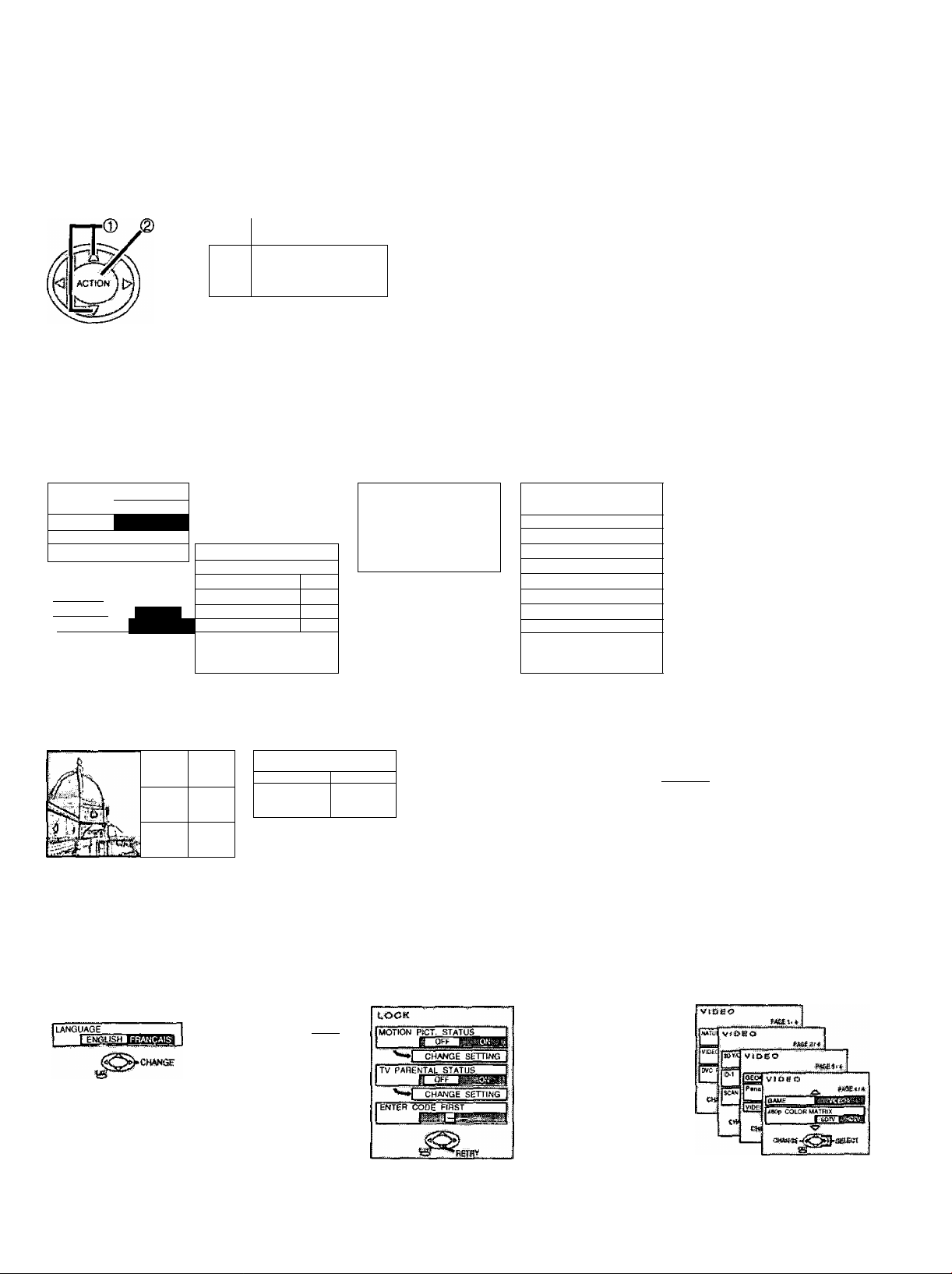
CH
Press to select LANGUAGE.
Press to display the LANGUAGE screen.
Press to select preferred language.
MENU
Press to exit menu.
MENU
STOMI
LANGUAGE
M iM
D PROGRAM CHANNELS \
laiLocK □
jE£3|CL0SED CAPTION ~\
1 Tivibeo
lÀNOyAOE
LANGUAGE
rENdusHBd;M!WJi.-!l
...............
1
58
Page 59

Programming The Illuminated Remote Control Using Access Codes
The remote control can be preset for other manufacturers, by utilizing the REMOTE MODE SELECTION BUTTONS for
CABLE, DTV, VCR, RCVR (a Receiver or Amplifier), DVD (DVD, CD, LD) ,DBS and AUX (for Cassette Player or a
VCR2)
(Details on remote control buttons to operate peripheral equipment — See page 61 to 63 and 64 to 66)
1 Setting up the remote using the numerical keys (When the code is known)
1
vol(
o
© ®
© ® ®
®
®
Press and hold the POWER and ACTION keys simultaneously for three full
seconds
After 3 seconds, all the illuminated mode keys will begin to flash
Release the POWER and ACTION keys
Press the desired mode key
The mode key will illuminate steadily, all others will go out
Enter the three digit set up code, by using the Remote Control Keyboard
If the correct code is entered, the mode key will blink twice and then go out
Now your remote is set for this code
Note:
If an incorrect number is entered (or there is an incomplete entry after 30 seconds), the key illumination goes out
(no blink) and the settings are unchanged
Device Operate Default
TV
VCR VCR ( Preset)
CBL
DBS DBS Boxes ( Preset) Panasonic Code
RCVR RCVR ( Preset)
AUX Cassette Players, VCR2 ( Preset)
DVD DVD & LD & CD Player ( Preset)
DTV
TV (Only Panasonic )
Cable Boxes ( Preset)
STB i Only Panasonic )
Panasonic Code
Panasonic Code
Panasonic Code
Technics Code
Technics Cassette Players Code
Panasonic DVD Code
Panasonic Code
59
Page 60

Operating peripheral equipment using the remote control
2 Setting to the remote using the step and set method
(When the code is not known)
Press and hold the POWER and
1
va ( (<J ( ACTION j C>l I ''O'-
ACTION keys simultaneously for three
full seconds
After 3 seconds, all the illuminated mode
keys will begin to flash
Release the POWER and ACTION key
Press the mode key
The mode key will illuminate steadily,
all others will go out
Press VOL “ ► “ key to step to the next
code
Press POWER to send a test signal in
that format
Continue doing this until the proper
device code is found, and the target
device responds
Once the code has been found, press
the ACTION key to lock it in
Notes.
• The step and set mode will start from the current device (not the beginning of the list,
except for the first time)
• The step and set mode works in the reverse direction using the VOL “ ◄ ” key
Infrared Remote Codes for Specific Components
Helpful Hint Write down the code numbers for your components in the space provided below This will serve as a
handy reference whenever you need to reprogram your remote control
CABLE
Cable Box
DBS
Digital Broadcast System
VCR
Video Cassette Recorder
RCVR
Receiver or Amplifier
CD
Compact Disc Player
LD
Laser Disc Player
60
other Component
Other Component
Other Component other Component
Other Component Other Component
Page 61

Operating peripheral equipment using the remote control
Infrared Codes Index
The remote control is capable of operating many brands of peripheral equipment. Refer to pages 61 and 62 for
programming procedures.
Note: The remote control memory is limited and therefore some models may not operate. The remote control is not
designed to control all features available in all models.
Note: After entering the proper infrared code, press the desired Mode Selection Button on the remote control. Refer to
pages 16 and 66 to 68, for details on operating peripheral equipment using the remote control.
VCR Infrared Codes Index
Maker List (VCR)
Maker Set Up No. Maker Set Up No.
ADMIRAL 200
AIWA 137, 160 PHILCO 150, 130,137, 125
AKAI
AUDIO DYNAMIC 240, 011
BELL & HOWELL 005,013 PIONEER 125
BROKSONIC
CANON 125, 135 150,310, 001,002
CITIZEN 006 QUASAR
CRAIG 005, 141,006 RADIO SHACK 170, 130, 005, 210
CURTIS MATHES 300, 130, 137 009, 241, 137
DAEWOO 250, 001, 130 RCA 170, 300,000, 125
DBX
DIMENSIA 300 002
EMERSON 250, 136,080, 003
FISHER
FUNAI 137,136,081 SANSUI 240, 136,081,520
GE
GO VIDEO 220,512 SCOTT 001,002,004, 009
GOLDSTAR
HITACHI 125, 300,000 136, 081
INSTANT REPLAY 130,125
JENSEN 240 000
JVC
KENWOOD 240„010, 006, 011 SHARP 200,210
LXI 137, 006, 000, 007
MAGNAVOX 150, 125, 130 SONY
MARANTZ 240,010, oil SV2000 137
MARTA 006 SYLVANIA
MEMOREX
MGA 230, 241,330, 340 TASHIRO 006
MINOLTA 000, 300 TEAC
MITSUBISHI 230, 241,330, 340 TECHNICS 100, 101,125, 130
MULTITECH
NEC 240,010, on, 190 VECTOR RESEARCH 011
OLYMPIC 130,125 WARDS 200,210, 009, 290
OPTIMUS
ORION 136, 081 YAMAHA 005,240, 010, oil
PANASONIC
PENNEY 130,000, 300, 005,
142, 014, 015, 016
081,136 PROSCAN
240,010, 011
135,243, 081 241, 137
005,008, 009, 007
170, 300, 130
006 230,241,330, 340
240,010,011, 190 SH INTOM
008, 005, 009 SINGER 050
130, 009
242, 243 TATUNG 240,010,011
242, 243 TEKNIKA 130, 137
330, 137, 004
140, 100, 200, 006 006
125, 130, 100, 101
240,010, oil
PENTAX
PHILIPS 150, 125,130
REALISTIC 130, 005,210, 009
SAMSUNG 220, 002, 004
SANYO 005, 009
SEARS
SIGNATURE 2000 137, 200
SYMPHONIC 137
TOSHIBA
ZENITH 290
000,011,300
136,081
300,000, 125, 130
100, 101, 125, 130
130,150,310, 001
005, 006, 007, 008
050
140, 141,142
150, 125, 130, 137
240,010.137,011
001,310
61
Page 62

Operating peripheral equipment using the remote control
CABLE CONVERTER BOX AND DVD, CD, LD PLAYERS Infrared Codes Index
Maker List (CBL)
Maker Set Ud No Maker
ABC 530
ARCHER 544, 531 PUSER
CABLEVIEW
CITIZEN 522, 005 REGAL
CURTIS
DIAMOND
EAGLE 541 REMBRANT
EASTERN 560
GCBRAND
GEMINI 522 SLMARK
GENERAL INSIEUME^ERROID360, 530,531,532 SPRUCER 005, 121
HAMLIN 720,730,731,900 TEXSCAN 810
HITACHI 003, 530
MACOM
MEMOREX 542 UNIVERSAL
MOVIETIME 544, 005 VIDEOWAY 006
OAK
PANASONIC
PHILIPS
PIONEER 001,260
005, 544
130, 131
530, 544, 531
544, 005
533, 520,521,522
122
350,130
003,004,005
710, 702,002
120, 121, 132
541, 542, 006
PULSAR 005,544
REALISTIC
REGENCY 560
SAMSUNG
SCIENTIFIC ATUNTA
STARGATE
TELEVIEW
TOCOM 700,701
TOSHIBA 004
UNIKA 544,531
VIEWSTAR 541,542
ZENITH 280, 000
2ENITHTORAKE SATELLITE
Set Up No
544
544
130, 350, 720, 730
731,900
702, 544, 005
005
122, 130, 131
005, 001
544,005
001,005
522,544
000
Maker List (DVD)
Maker
DENON 100
FERGUSON 110
NORDMENDE 110
MITSUBISHI 150 THOMSON 110
PANASONIC
PIONEER
Set Up No
100
120 YAMAHA 100
Maker
RCA 110
SABA 110
SONY
TOSHIBA 130
Set Up No.
140
Maker List (CD)
Maker
CARVER 550
DENON 600
FISHER 405
HARMAN/KARON
JVC
KENWOOD
MAGNAVOX 550
MARANTZ 550 TECHNICS
MCINTOSH 460
OPTIMUS 430,459
PANASONIC
Set Up No.
459,460,462
590,591,670
400, 401,450, 670
500,501,530
Maker
PHILIPS 550
PIONEER 430
QUASAR
SANYO 405
SHARP 600
SHERWOOD
SONY
VICTOR
YAMAHA 402, 403, 404
Maker List (LD)
Maker
PANASONIC
PIONEER
SONY
Set Up No
501,530, 500
459
540
530, 500, 501
590,591,670
Set Up No
200,201 235,380
370
240, 241,242, 243
62
Page 63

Operating peripheral equipment using the remote control
CASSETTE PLAYERS, RECEIVERS, AMPLIFIERS, and DBS Infrared Codes Index
Maker List (TAPE)
Maker
PANASONIC
Set Up No.
700, 730 TECHNICS
Maker List (RCVR)
Maker
ADMIRAL
AIWA
DENON
FISHER
GARRARD
HARMAN/KARDON 057, 150
JENSEN
JVC
KENWOOD 000, 050
MEGNAVOX 162
MARANTZ
MCINTOSH
NAKAMICHI 031
ONKYO
OPTIMUS 003, 162, 171, 170
Set Up No.
110
160, 161
200,201,202
004
055
164
190, 191
151
058
051,056
Maker
Maker
PANASONIC
PHILIPS
PIONEER
QUASAR 101,100, 130
RCA
SANSUI 003, 053, 320
SHARP 200, 203
SONY 140
SOUND DESIGN 220
TEAC
TECHNICS
VICTOR 190, 191
YAMAHA 001,002
Set Up No.
700, 730
Set Up No.
101, 100, 130
150
030,032
003, 030, 162, 171
170
054, 055, 053
130, 100,101
Maker
ECHOSTAR
G.E.
HNS (HITACHI) 050
PANASONIC
PHILIPS 001,002
Set Up No.
110
170
100
Maker List (DBS)
Maker Set Up No.
PRIMESTAR 391
RCA 170
SONY 390
TOSHIBA 000
UNIDEN 001,002
63
Page 64

Operating peripheral equipment using the remote control
Remote Control
Quick Reference Functional Key Control
KEY MODE FUNCTION
© @ (D
© ® ©
® ® ®
®
TV/VIOEO
o
TV. DTV, VCR
AUX (VCR2)
CABLE, DBS
RCVR
(Receiver/Amplifier)
DVD (DVD, CD, LD) Selects Track Number
TV
ALL COMPONENTS
Select Channel
1 Selects Video 1
2 Selects Video 2
3 Selects Video 3
4 Selects Video 4
5 Selects CD
6 Selects Tuner
7 Selects Phone
8 Selects Tape
9 Selects AUX
Selects TV Input Mode
Turns On and Off Select Components
__
MUTE
o
%
%
CH
CH
___
TOL
TV VCR, DBS, DTV
CABLE
DVD
RCVR (Receiver/Amplifier)
AUX (Cassette)
Mutes TV Sound
Mutes Cable Sound
Mutes TV/RCVR Sound
Mutes Audio
RCVR Mute
TV TV Mode Selection for Remote Control
CABLE Cable Mode Selection for Remote Control
DBS
DBS Mode Selection for Remote Control
VCR VCR Mode Selection for Remote Control
Receiver/Amplifier Receiver/Amplifier Mode Selection for Remote Control
Digital Video Disc
Cassette Tape Player,
VCR2
TV
VCR
CABLE
DBS
DVD (DVD)
DVD (CD)
DVD (LD)
RCVR
TV VCR
CABLE
DBS
DVD (DVD)
DVD (CD)
DVD (LD)
RCVR
DVD (DVD, CD, LD) Mode Selection for Remote Control
AUX Mode Selection for Remote Control
Enables User to Operate a Tape Cassette Player, or VCR2
TV Channel Up/Down
VCR Channel Up/Down
Channel Up/Down
Channel Up/Down, Navigation Up/Down
Navigation Up/Down
Next Track/Previous Track
Next Chapter/Previous Chapter
Tuner +/TunerTV Volume Up/Down
Cable Volume Up/Down
Audio Track +/-, Navigation Right/Left
Navigation Right/Left
RCVR Volume Up/Down
TV Volume Up/Down
RCVR Volume Up/Down
64
Page 65

Operating peripheral equipment using the remote control
Remote Control
Quick Reference Functional Key Control
KEY
R-TUNE
^ 1
( (<|f ACTION } Cw 1
VV V
№OnECAU,
o
REW
O
SPLIT
FF
&
e
SEARCH
STOP
®
VCR^C
<s
SWAP
&
STJU
FREEZE
TVVCH
OPtHUME
MODE FUNCTION
TV
CABLE
DBS
DVD (DVD)
DVD (CD)
DVD (LD) Side A/B
DTV Prev. Ch
AUX (Tape Cassette Player)
TV
CABLE Enter
DBS
DTV
DVD
TV, CBL
VCR
DBS
DTV
DVD (DVD)
DVD (CD)
DVD (LD)
VCR
DVD (DVD. LD)
DVD (CD) Search REW
RCVR
AUX (Tape Cassette Player)
TV
VCR
DVD (DVD, LD) Skip Search »
DVD (CD) Search FF
RCVR Surround +
AUX (Tape Cassette Player)
VCR
DVD (DVD, CD, LD)
AUX (Tape Cassette Player)
TV SPLIT Search
VCR
DVD (DVD, CD, LD)
AUX (Tape Cassette Player)
VCR, CABLE
DBS
DTV
AUX (Tape Cassette Player)
TV
VCR
DVD (DVD, LD) Still
DVD (CD)
AUX (Tape Cassette Player)
TV
VCR
DVD (DVD, CD, LD)
AUX (Tape Cassette Player)
Selects Previously Tuned Channel
Selects Previously Tuned Channel
Selects Previously Tuned Channel
Selects Previous Title
Selects Next Disc
Selects Tape Cassette Player A or B
Activities TV Menus
DBS Action
STB Action
Select
Display Information (Channel, Time, Audio Mode, Power Save Mode)
Display Current VCR Settings
Display Current DBS Settings
Display Current DTV Settings
Display Current DVD Settings
Display Time format
Display Current LD Settings
VCR REW
Skip Search «
Surround -
Tape REW
SPLIT ON/OFF
VCR FF
Tape FF
VCR Play
Play
Tape Play
VCR Stop
Stop
Tape Stop
VCR Record
DBS Record
Info (EPG)
Tape Record
SPLIT Swap
VCR Pause
Pause
Tape Pause
SPLIT Freeze
TVA/CR Switch
Open/Ciose
Tape Open/Close
65
Page 66

Operating peripheral equipment using the remote control
Remote Control
Quick Reference Functional Key Control
KEY
ASPECT
o
AV-ADJ TV
TV TV Aspect
DBS DBS Aspect
DTV (STB) STB Aspect
VCR VCR Channel Up
CABLE TV Channel Up
DBS DBS Channel Up
DVD (DVD)
DVD (CD)
DVD (LD)
RCVR Center +
VCR VCR Channel Down
CABLE
DBS DBS Channel Down
DVD (DVD)
DVD (CD)
DVD (LD)
RCVR
CD
NORMAL
TV
CD
TV
GAME DBS
C
_
)
RH-SPLIT DBS
o
EXIT
CD
PROG
O
GUIDE
o
MENU
o
DVD SkipRCVR Tuner TV RH-SPLIT
DVD Skip +
RCVR
TV
DBS
DTV (STB) Exit (EPG)
DBS
DTV (STB)
DBS DBS Guide
DTV (STB) Guide (EPG)
TV
DBS DBS Menu
DVD (DVD) DVD Menu
DVD (CD)
DVD (LD)
DTV (STB)
MODE
FUNCTION
Slow +
Repeat
LD Side A
TV Channel Down
Slow -
Random
LD Side B
Center AV-Adjust
NORMAL
Game
DBS Page Down
DBS Page Up
Tuner+
Exit from Menu Screen
DBS Exit
DBS Program
STB Program
TV Menu
STB Menu
66
Page 67

During normal broadcast (VHF/UHF)
Symptoms
Power does not turn ON
Remote control does not
function
Image shakes
Image is not clear
Color patches or no color
Image appears doubled or
tripled.
Spots appear in images,
images shake, or color patches
appear in the four corners.
When the TV set is turned on
in a dark room, the outer edges
of the screen spark
momentarily.
Checks
• Is the power plug plugged in?
• If the power does not turn on using the remote, check if the TV set is
turned on.
• Are the batteries dead or inserted incorrectly?
• Is the remote control sensor in direct light of florescent lamps or other
strong sources of light?
• Is the antenna or antenna cable old, broken or shorted?
• Is the antenna cable connected properly?
• When using a VCR and selecting channels on the TV, is the TVA/IDEO
mode for the VCR set to TV?
• Is the antenna facing the right direction?
• Is the antenna receiving any signals reflected off mountains or buildings.
• Is the TV being affected by geomagnetism or other interference
(automobiles and trains, high voltage power lines, neon, motors,
magnetic steel frames, steel windows, etc.)? Turn off the power for
approx. 20 min. and turn back on or change positioning of the TV set. If
this does not fix the problem, the TV needs magnetic shielding.
• Due to the internal structure of the CRT set, some parts of the fluorescent
components spark, (created by high voltage) when the TV set is turned
on. This is not a malfunction.
Page
17
7
8, 9, 10
-
-
-
Unclear or overly bright colors
on parts of the screen
Left and right ends of the
screen, columns and frames
appear curved.
A black stripe appears for a
moment when changing
channels using the VCR.
During Panasonic AUTO
mode, the screen size
sometimes changes.
Images disappear at the top
and bottom of the screen
During ZOOM or JUST modes,
the image is cut off at the top
and bottom.
A clicking and buzzing sound
is made when the TV is turned
on.
• When white is displayed on a certain part of the screen for a while, the
white portion tends to tint with color. When the bright image disappears,
the screen will return to its normal color.
• Receiving broadcast or changes in brightness on the screen can cause
curves on the screen.
• The image distorts when channels are changed.
• Depending on the program content, even when the screen is supposed
to automatically zoom, if the beginning scene is dark, it may take a
while for it to zoom.
• During a 4:3 screen, if the top and bottom of the image is dark, it may
zoom.
• When using 16:9 image software, there is no picture at the top and
bottom of the screen (cinema vision size software, etc.).
• Has the screen position been changed?
If so, adjust screen positioning.
• This is the sound of the Geomagnetic correction function creating a
beautiful color picture. This is not a malfunction.
-
-
22,23
-
32
57
67
Page 68

Troubleshooting
During normal broadcast (VHF/UHF)
Symptoms Checks
Image is skewed
Channel number remains
displayed.
The TV set makes a cracking
sound
This could be a geomagnetic
effect. (If installed facing
south, then image slants
down to the right; when facing
north, slants down to the left.)
Perform geomagnetic
correction.
' Press the INFO/RECALL button.
During VIDEO input, channel number is displayed until an image is
displayed.
If there are no problems with image or sound, it is the sound of the
cabinet shrinking due to room temperature changes. This is not a
malfunction.
Page
57
29
68
Page 69

Page 70

Page 71

Power Source
AC 120 V, 60 Hz
Power Consumption
CRT
Screen Size
Channel Capability-181
Speaker
Sound
Audio Output
Headphones
FEATURES
Accessories Supplied
Operating Conditions
Average use : 177 W (Maximum Current 3.7 A)
Stand-by condition : 0.36 W
30-inch, 16:9 aspect ratio
25.95 ”{659.1 mm)(W) x 14.59 ” {370.7 mm) (H) x 29.77 ” {756.2 mm) (diagonal)
VHF-12 : UHF-56 : Cable-125
5 Speakers
21 W [7W-i-7W-h7W] (10%THD)
M3 {3.5 mm) Jack x 2
Two screen display fuctions 3D Y/C FILTER
AFB circuit installation 5 Speakers
CLOSED CAPTION V-Chip
Remote control Transmitter EUR511162
R6 (AA) Battery x 2
Temperature : 34 °F -104 °F (0 ° - 40 °C)
Humidity : 20 % - 80 % (non-condensing)
Connection Terminals
Dimensions
(WxDxH)
Weight (Mass)
AV INPUT 1- 4 VIDEO 1.0 Vp-p (75 n)
(Phono Jack Type)
S-VIDEO Y : 1 Vp-p (75 Q), C : 0.286 Vp-p (75 ii)
(Mini DIN 4-pin)
AUDIO L-R 0.5 Vrms
(Phono Jack Type x 2)
AV PROG. OUT VIDEO 1.0 Vp-p (75 0)
(Phono Jack Type)
S-VIDEO Y : 1 Vp-p (75 Q), C : 0.286 Vp-p (75 Q)
(Mini DIN 4-pin)
AUDIO L-R 0.5 Vrms
(Phono Jack Type x 2)
TO AUDIO AMP AUDIO L-R 0.5 Vrms
(Phono Jack Type x 2)
COMPONENT VIDEO Y 1.0 Vp-p (including synchronization)
INPUT1-2 Pb/Pr ±0.35 Vp-p
AUDIO L-R 0.5 Vrms
(Phono Jack Type x 2)
30.6 ” (777 mm) x 21.1 ” (535.3 mm) x 22.7 ” (576 mm)
128 lb. (58 kg) Net
Note:
Design and Specifications are subject to change without notice. Weight and Dimensions shown are approximate.
71
Page 72

Customer’ Record
The model number and serial number of this product can be found on its back cover You should note this
serial number in the space provided below and retain this book, plus your purchase receipt, as a permanent
record of your purchase to aid in identification in the event of theft or loss, and for Warranty Service purposes
Model Number CT-30WX50
Panasonic Consumer Electronics
Company, Division of Matsushita
Electric Corporation of America
One Panasonic Way Secaucus
New Jersey 07094
Serial Number
Panasonic Sales Company,
Division of Matsushita Electric of
Puerto Rico Inc. (“PSC”)
Ave 65 de Infanteria, Km 9 5
San Gabriel Industrial Park,
Carolina, Puerto Rico 00985
Printed in Japan
MBS0601S1071(MS)
 Loading...