

Panasonic CT-27SF13U Owner’s Manual
Color Television
Operating Instructions
®
Read these instructions completely before operating this set.
Contents subject to change without notice or obligation.
Copyright 1996 by Matsushita Electric Corporation of America.
All rights reserved. Unauthorized copying and distribution is a violation of law.
CT-27SF13
CT-31SF13
Printed in LISA
TQB2AA0033
Safety Instructions
WARNING
WARNING: To reduce the risk of electric shock do not remove cover or back. No
user-serviceable parts inside. Refer servicing to qualified service personnel.
The lightning flash with ar-
is intended to tell the user
__ row-head within a triangle __
that parts inside the product
are arisk of electric shock to
persons.
The exclamation point within
a triangle is intended to tell
the user that important oper-
ating and servicing instruc-
tions are in the papers with
the appliance.
Note to CATV System Installer: This reminder is provided to call the CATV system installer's attention to Article
820-40 of the NEC that provides guidelines for proper grounding and, in particular, specifies that the cable ground shall be
connected to the grounding system of the building, as close to the point of cable entry as practical.
Safety Instructions for Television Receivers
1. Read and apply the operating instructions provided with your television receiver.
2. Read all of the instructions given here and retain them for later use.
3. Unplug this television receiver from the wall outlet before cleaning. Do not use liquid or aerosol cleaners. Use a damp
cloth for cleaning.
4. Do not use attachments not recommended by the television receiver manufacturer as they may cause hazards.
5. Do not use this television receiver near water. For example: Avoid placing it near a bathtub, washbowl, kitchen sink, or
laundry tub, in a wet basement, or near a swimming pool, etc.
6. Do not place this television receiver on an unstable cart, stand or table. The television receiver may fall, causing serious
injury to a child or adult, and serious damage to the appliance. Use only with a cart or stand recommended by the
manufacturer, or sold with the television receiver. Wall or shelf mounting should follow the manufacturer's instructions,
and should use a mounting kit approved by the manufacturer.
6A. An appliance and cart combination should be moved with care. Quick stops, excessive force, and _l_J_"
uneven surfaces may cause the appliance and cart combination to overturn.
7. Slots and openings in the cabinet and the back or bottom are provided for ventilation, and to insure
reliable operation of the television receiver and to protect it from overheating. These openings must not be blocked or
covered. The openings should never be blocked by placing the television receiver on a bed, sofa, rug or other similar
surface. This television receiver should never be placed near or over a radiator or heat register. This television receiver
should not be placed in a built-in installation such as a bookcase unless proper ventilation is provided.
8. Operate only from the type of power source indicated on the marking label. If you are not sure of the type of power
supplied to your home consult your television dealer or local power company. For television receivers designed to
operate from battery power, refer to the operating instructions.
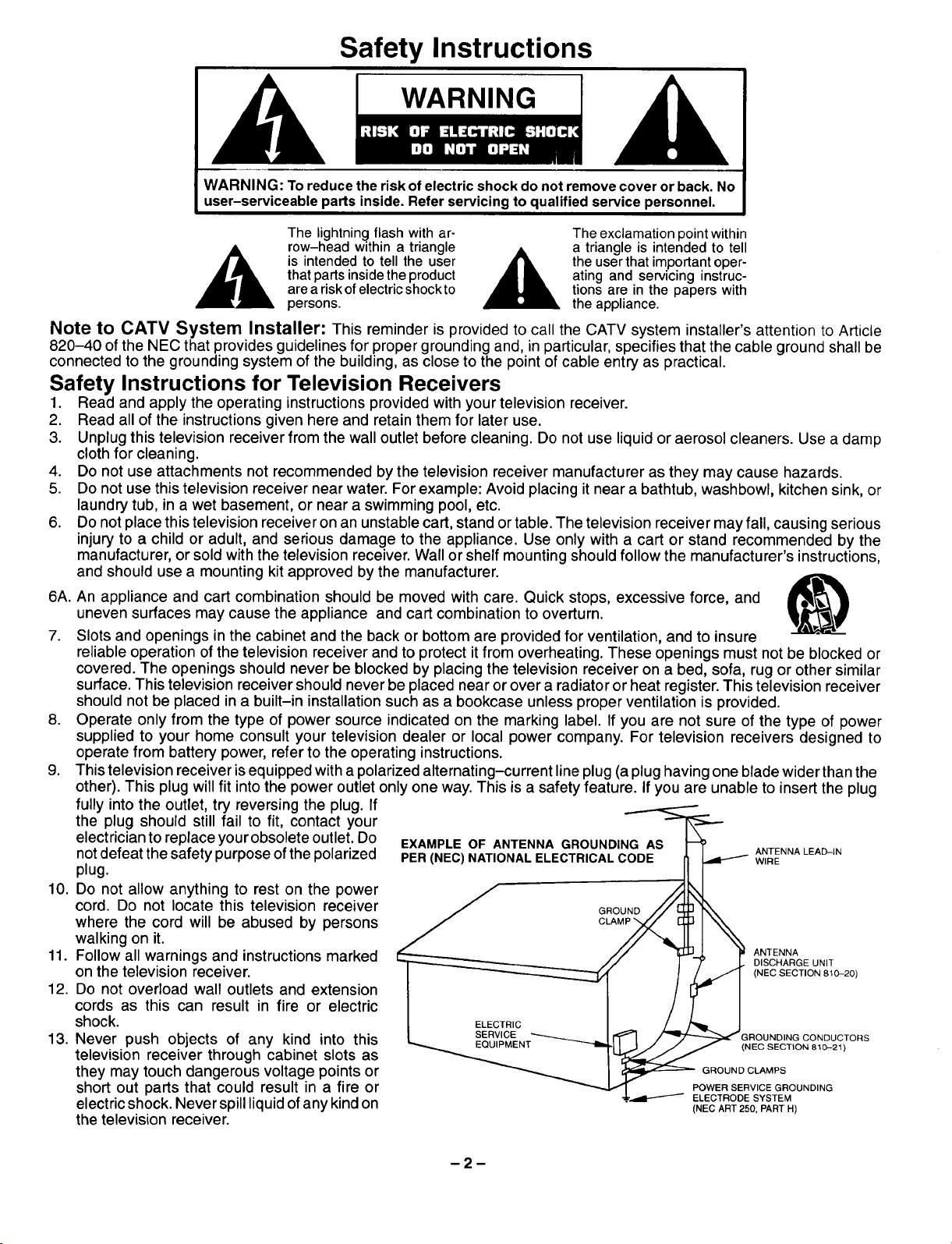
9. This television receiver is equipped with a polarized alternating-current line plug (a plug having one blade wider than the
other). This plug will fit into the power outlet only one way. This is a safety feature. If you are unable to insert the plug
the plug should still fail to fit, contact your
fully into the outlet, try reversing the plug. If N_.=.....=_.----GAS'_
electrician to replace your obsolete outlet. Do EXAMPLE OF ANTENNA GROUNDI ANTENNALEAD-IN
notdefeat the safety purposeofthe polarized PER(NEC)NATIONALELECTRICALCODE I_ J._ WIRE
plug.
10. Do not allow anything to rest on the power
cord. Do not locate this television receiver _ GROUND// L_ r'_
where the cord will be abused by persons J CLAMP'>(./ _1\ \
walking on it.
11. Follow all warnings and instructions marked ANTENNA
on the television receiver. (NEC SECTION 810-20)
DISCHARGE UNIT
12. Do not overload wall outlets and extension
cords as this can result in fire or electric
shock, i ELECTRIC / _ J
13. Never push objects of any kind into this "_..= EQUIPMENT _"-"_iEQUIPMENT _"-"_i II JIJ J _ (NEC SECTION 810-21)
I SERVICE _ _ _GROUNDING CONDUCTORS
television receiver through cabinet slots as _ _;_,d__=_J_
short out parts that could result in a fire or POWERSERVICEGROUNDING
they may touch dangerous voltage points or _ _GROUNDCLAMPS
electric shock. Never spill liquid of any kind on (NECART250.PARTH)
ELECTRODE SYSTEM
the television receiver.
14.Ifanoutsideantennaisconnectedtothetelevisionequipment,besuretheantennasystemisgroundedsoastoprovide
someprotectionagainstvoltagesurgesandbuiltupstaticcharges.IntheU.S.Section810oftheNationalElectrical
CodeandinCanadaPart1oftheCanadianElectricalCodeprovidesinformationwithrespecttopropergroundingofthe
mastandsupportingstructure,groundingofthelead-inwiretoanantennadischar.geunit,sizeofgroundingconductors,
locationofantenna-dischargeunit,connectiontogroundingelectrodes,andrequirementsforthegroundingelectrode.
SeeFigure.
15.Foraddedprotectionforthistelevisionreceiverduringalightningstorm,orwhenitisleftunattendedandunusedforlong
periodsoftime,unplugitfromthewalloutletanddisconnecttheantenna.Thiswillpreventdamagetothereceiverdueto
lightningandpower-linesurges.
16.Anoutsideantennasystemshouldnotbelocatedinthevicinityofoverheadpowerlinesorotherelectriclightorpower
circuits,orwhereitcanfallintosuchpowerlinesorcircuits.Wheninstallinganoutsideantennasystemextremecare
shouldbetakentokeepfromtouchingsuchpowerlinesorcircuitsascontactwiththemmightbefatal.
17.Unplugthistelevisionreceiverfromthewalloutlet,andreferservicingtoqualifiedservicepersonnelunderthefollowing
conditions:
a. Whenthepowercordorplugisdamagedorfrayed.
b. Ifliquidhasbeenspilledintothetelevisionreceiver.
c. Ifthetelevisionreceiverhasbeenexposedtorainorwater.
d. Ifthetelevisionreceiverdoesnotoperatenormallybyfollowingtheoperatinginstructions.Adjustonlythosecontrols
thatarecoveredbytheoperatinginstructionsasimproperadjustmentofothercontrolsmayresultindamageandwill
oftenrequireextensiveworkbyaqualifiedtechnicianto restorethetelevisionreceivertonormaloperation.
e. Ifthetelevisionreceiverhasbeendroppedorthecabinethasbeendamaged.
f. Whenthetelevisionreceiverexhibitsadistinctchangeinperformance- thisindicatesa needforservice.
18.Donotattempttoservicethistelevisionreceiveryourselfasopeningorremovingcoversmayexposeyoutodangerous
voltageorotherhazards.Referallservicingtoqualifiedservicepersonnel.
19.Whenreplacementpartsarerequired,besuretheservicetechnicianhasusedreplacementpartsspecifiedbythe
manufacturerthathavethesamecharacteristicsastheoriginalpart.Unauthorizedsubstitutionsmayresultinfire,
electricshock,orotherhazards.
20.Uponcompletionofanyserviceorrepairstothistelevisionreceiver,asktheservicetechniciantoperformroutinesafety
checkstodeterminethatthetelevisionisinsafeoperatingcondition.
21.WARNING: To prevent fire or shock hazard, do not expose this appliance to rain or moisture.
22, CAUTION: TO PREVENT ELECTRIC SHOCK DO NOT USE THIS (POLARIZED) PLUG WITH A RECEPTACLE OR
OTHER OUTLET UNLESS THE BLADES CAN BE FULLY INSERTED TO PREVENT BLADE EXPOSURE.
NOTE: This equipment isdesigned to operate in the U.S.A., Canada and other countries where the broadcasting system and
AC house current is exactly the same as in the U.S.A. and Canada.
Important Information Regarding Use of Video Games, Computers, Teletext or Other Fixed Image Displays.
The extended use of fixed image program material can cause a permanent "shadow image" on the picture tube. This
background image is viewable on normal programs in the form of a stationary fixed image. This type of irreversible picture
tube deterioration can be limited by observing the following steps:
A. Reduce the brightness/contrast setting to a minimum viewing level.
B. Do not display the fixed image for extended periods of time.
C. Turn the power off when not in actual use.
NOTE: The marking or retained image on the picture tube resulting from fixed image use is not an operating defect and as
such is not covered by Warranty. This product isnot designed to display fixed image patterns for extended periods of
time.
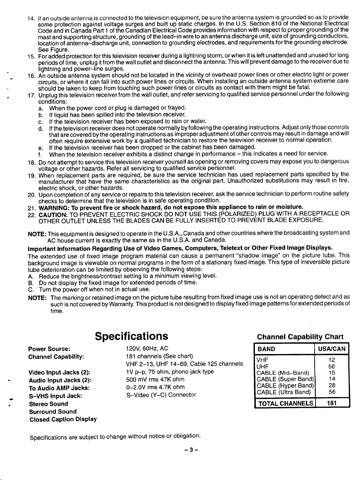
Channel Capability Chart
BAND
VHF
UHF
CABLE (Mid-Band)
CABLE (Super Band)
CABLE (Hyper Band)
CABLE (Ultra Band)
TOTAL CHANNELS
USNCAN
12
56
15
14
28
56
181
Power Source:
Channel Capability:
Video Input Jacks (2):
Audio Input Jacks (2):
To Audio AMP Jacks:
S-VHS Input Jack:
Stereo Sound
Surround Sound
Closed Caption Display
Specifications
120V, 60Hz, AC
181 channels (See chart)
VHF 2-13, UHF 14~69, Cable 125 channels
1V p-p, 75 ohm, phono jack type
500 mV rms 47K ohm
0~2.0V rms 4.7K ohm
S-Video (Y-C) Connector
Specifications are subject to change without notice or obligation.
m 3 --
Introduction
Congratulations on Your New Purchase
Your new video component features an all solid state chassis which is designed to give you many years of enjoyment. It
was thoroughly tested and adjusted at the factory for best performance.
In order for you to take full advantage of your new video component, please read and follow the installation and operating
instructions supplied with this product.
Customer's Record
The model and serial number of this product may be found on its back cover. You should note the model and serial number
in the space provided and retain this book as a permanent record of your purchase to aid in identification in the event of
theft or loss.
Model Number: Serial Number:
Table of Contents
Safety Instructions ............................. 2
Specifications ................................. 3
Introduction ................................... 4
Installation .................................... 6
Receiver Location .............................. 6
Optional External Equipment Connections ........ 6
AC Power Supply Cord ......................... 6
Battery Installation ............................. 6
Antenna/Cable Connections ..................... 7
Other Video Equipment ......................... 7
Optional Equipment Connection and Operation .. 8
Stereo Connection (To Audio AMP) .............. 8
Video/Audio Connection ........................ 8
S-Video Connection ............................ 9
Quick Reference Functional Key Chart ......... 10
Location of Controls for the Remote Unit ....... 11
Basic Remote Control Functions ................ 11
Remote Control Quick Reference Functional
Key Chart ................................. 12
Control Operation ............................. 14
Power Button ................................. 14
Volume Buttons ............................... 14
TVNideo Button .............................. 14
Channel Change (UP/DOWN) .................. 14
Numeric Keypad (0 through 9 Buttons) .......... 14
VCR Function Buttons ......................... 14
Recall Button ................................. 15
R-Tune (Rapid Tune) Button ................... 15
Mute Button .................................. 15
Multi Button .................................. 15
Main Menu (Trilingual Animated Icons) ......... 16
Language Menu ............................ 16
Picture Adjustments ........................... 17
Picture Norm ............................... 17
Color, Tint, Brightness, Picture and
Sharpness Adjustments .................... 17
Color Temp (Temperature) ................... 17
Auto Color ................................. 18
Video NR .................................. 18
Audio Adjustment ............................. 19
Audio Norm ................................ 19
Bass, Treble and Balance .................... 19
Mode - Stereo/SAP/Mono ................... 20
[TV] Speaker ............................... 20
Surround .................................. 21
AI Sound .................................. 21
Input Select .................................. 22
Main (Picture) Input Selection ................ 22
Timer Features ............................... 23
Sleep Timer ................................ 23
Program Timer ............................. 24
Lockout Features ............................. 25
Lockout Mode .............................. 25
Unlock .................................... 26
Favorite Channel Feature ...................... 27
Channel Scan .............................. 27
Favorite Channel Select ..................... 27
Channel Caption Feature ...................... 28
Preset Caption ............................. 28
Manual Caption ............................ 29
Trilingual Menu Selection ...................... 30
Language Selection ......................... 30
n4D
Table of Contents (cont.)
Set Up Features .............................. 31
Clock (Auto) ............................... 31
Clock (Manual) ............................. 33
Set Day ................................... 34
Mode (TV or Cable) ......................... 35
Auto Program .............................. 36
Manual Program ............................ 37
On Mute .............................. 38
Mode ................................ 39
Programming the Remote Control
Using Access Codes ....................... 40
VCR Infrared Codes Index ..................... 41
Cable Converter Box and CD Players
Infrared Codes Index ...................... 42
Cassette Players, AV Receivers, and Amplifiers
Infrared Codes Index ...................... 43
Laser Disc, DSS, Television, and DVD
Infrared Codes Index ...................... 44
Care and Cleaning ............................ 45
Troubleshooting Chart ........................ 46
Power Loss ................................... 47
-5-
Installation
Receiver Location
This unit is intended to be used with an optional stand or entertainment center. L;onsult yuuJdeale_ Jor_va_lable uptJo__.
Locate for comfortable viewing. Avoid placing where sunlight or other bright light (including reflections) will fall on the
screen.
Use of some types of fluorescent lighting can reduce remote control transmitter range.
Adequate ventilation is essential to prevent internal component failure. Keep away from areas of excessive heat or
moisture.
To insure optimum color purity do not position magnetic equipment (motors, fans, other speakers, etc.) nearby.
Optional External Equipment Connections
The Video/Audio connections between components can be made with shielded video and audio cables. For best
performance, video cables should utilize 75 ohm coaxial shielded wire. Cables are available from your dealer or
electronic supply house.
Before you purchase any cables, be sure you know what type of output and input connectors your various components
require. Also determine the length of cable you'll need.
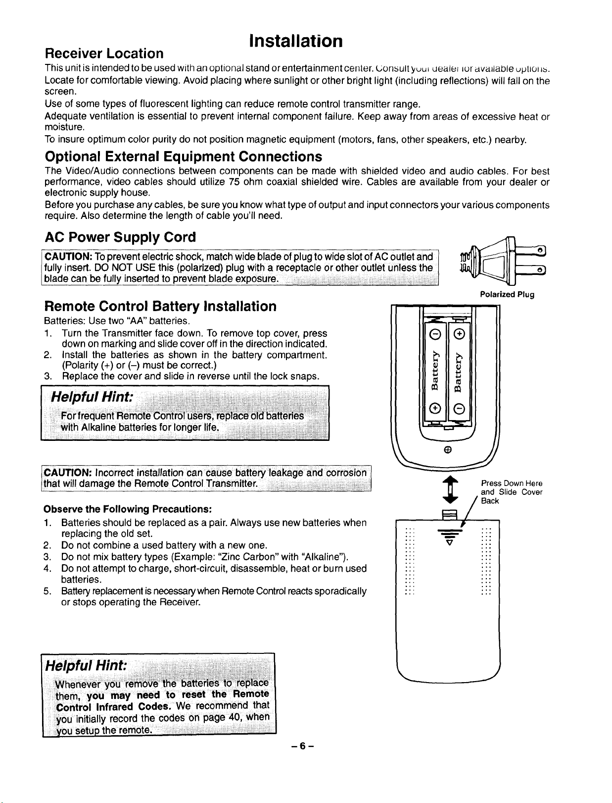
AC Power Supply Cord
CAUTION: To prevent electric shock, match wide blade of plug to wide slot of AC outlet and 1
fully insert. DO NOT USE this (polarized) plug with a receptacle or other outlet unless the
blade canbe fully inserted to prevent blade exposure: _ i
Polarized Plug
Remote Control Battery Installation
Batteries: Use two "AA" batteries.
1. Turn the Transmitter face down. To remove top cover, press
down on marking and slide cover off in the direction indicated.
2. Install the batteries as shown in the battery compartment.
(Polarity (+) or (-) must be correct.)
3. Replace the cover and slide in reverse until the lock snaps.
Helpful H nt:
Observe the Following Precautions:
1. Batteries should be replaced as a pair. Always use new batteries when
replacing the old set.
2 Do not combine a used battery with a new one.
3 Do not mix battery types (Example: "Zinc Carbon" with "Alkaline")
4. Do not attempt to charge, short-circuit, disassemble, heat or burn used
batteries.
5. Batteryreplacementisnecessary when Remote Control reactssporadically
or stops operating the Receiver.
E)
and Slide Cover
Press Down Here
/ Back
°,
v
.,.
J
-6-
Installation (cont.)
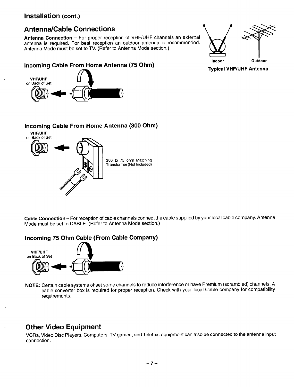
Antenna/Cable Connections
Antenna Connection - For proper reception of VHF/UHF channels an external
antenna is required. For best reception an outdoor antenna is recommended.
Antenna Mode must be set to TV. (Refer to Antenna Mode section.)
Incoming Cable From Home Antenna (75 Ohm)
VHF/UHF
on BackofSet
Incoming Cable From Home Antenna (300 Ohm)
VHF/UHF
on Back of Set
Indoor Outdoor
Typical VHF/UHF Antenna
300 to 75 ohm Matching
Transformer (Not Included)
Cable Connection - For reception of cable channels connect the cable supplied by your local cable company. Antenna
Mode must be set to CABLE. (Refer to Antenna Mode section.)
Incoming 75 Ohm Cable (From Cable Company)
VHF/UHF
on Back of Set
NOTE: Certain cable systems offset some channels to reduce interference or have Premium (scrambled) channels. A
cable converter box is required for proper reception. Check with your local Cable company for compatibility
requirements.
Other Video Equipment
VCRs, Video Disc Players, Computers, TV games, and Teletext equipment can also be connected to the antenna input
connection.
-7-
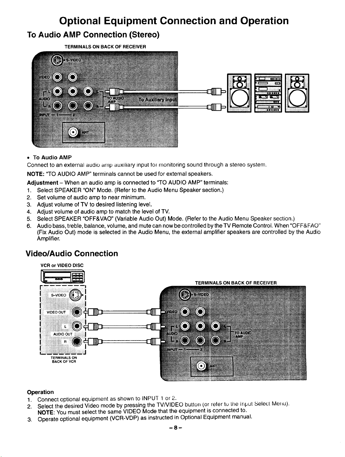
Optional Equipment Connection and Operation
To Audio AMP Connection (Stereo)
TERMINALS ON BACK OF RECEIVER
• To Audio AMP
Connect to an external audio amp auxiliary input tor monitoring sound through a stereo system.
NOTE: '%0 AUDIO AMP" terminals cannot be used for external speakers.
Adjustment - When an audio amp is connected to 'qO AUDIO AMP" terminals:
1. Select SPEAKER "ON" Mode. (Refer to the Audio Menu Speaker section.)
2. Set volume of audio amp to near minimum.
3. Adjust volume of TV to desired listening level.
4. Adjust volume of audio amp to match the level of TV.
5. Select SPEAKER "OFF&VAO" (Variable Audio Out) Mode. (Refer to the Audio Menu Speaker section.)
6. Audio bass, treble, balance, volume, and mute can now be controlled by the TV Remote Control. When "OFF&FAO"
(Fix Audio Out) mode is selected in the Audio Menu, the external amplifier speakers are controlled by the Audio
Amplifier.
Video/Audio Connection
VCR or VIDEO DISC
TERMINALS ON BACK OF RECEIVER
TERMINALS ON
BACK OF VCR
Operation
1. Connect optional equipment as shown to INPU-[ 1 or 2.
2. Select the desired Video mode by pressing the TVNIDEO button (or reler tu the Input Select Meflu).
NOTE: You must select the same VIDEO Mode that the equipment is connected to.
3. Operate optional equipment (VCR-VDP) as instructed in Optional Equipment manual.
-8-
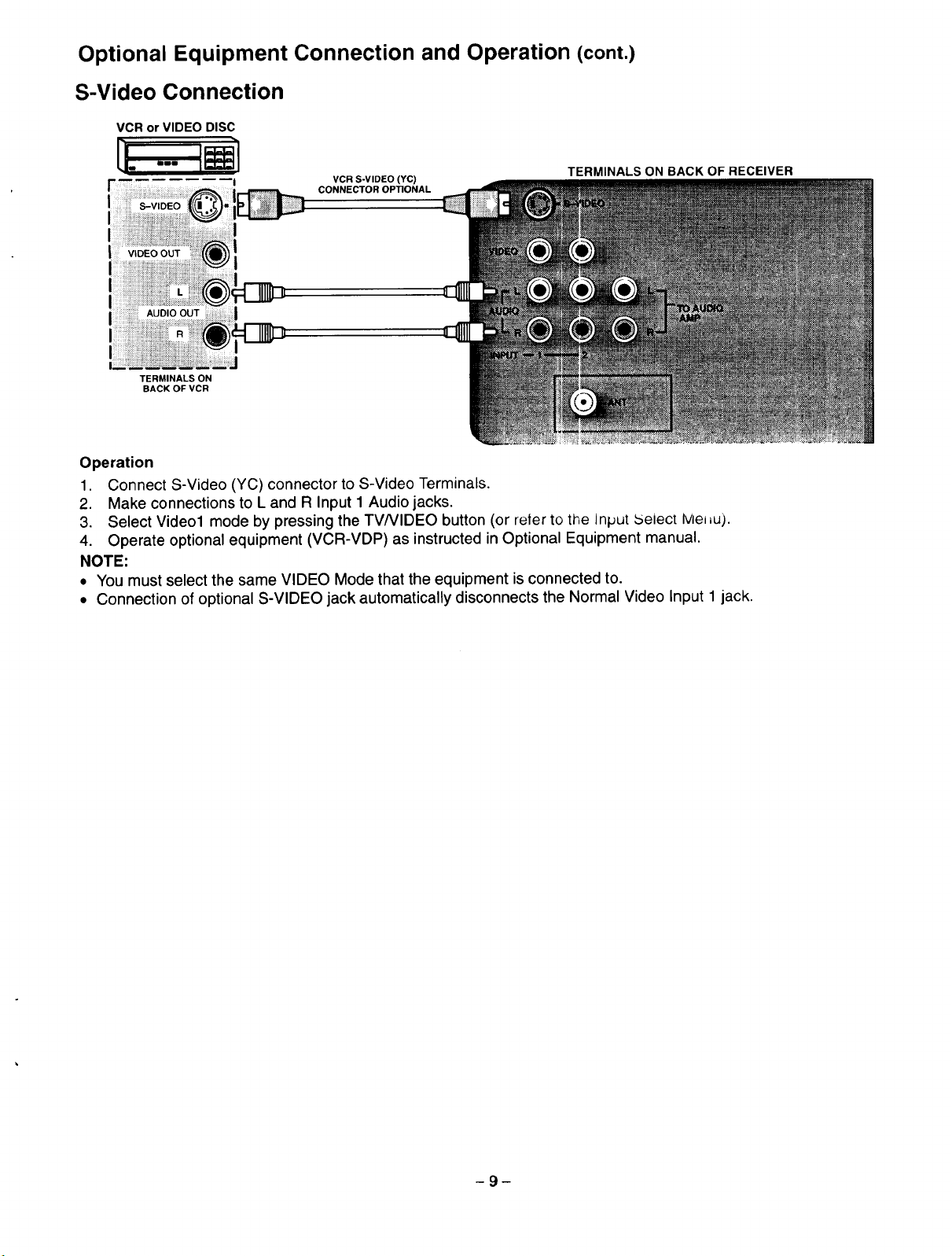
Optional Equipment Connection and Operation (cont.)
S-Video Connection
VCR or VIDEO DISC
VCR S-VIDEO (YC)
CONNECTOR OPTIONAL
TERMINALS ON BACK OF RECEIVER
i
lli!iiii!Tiiiiiiiiiiiii!iiiiiiiiii!iiiiiiiiiiiiii,
TERMINALS ON
BACK OF VCR
Operation
1. Connect S-Video (YC) connector to S-Video Terminals.
2. Make connections to L and R Input 1 Audio jacks.
3. Select Video1 mode by pressing the TVNIDEO button (or reter to the Input _elect Me=_u).
4. Operate optional equipment (VCR-VDP) as instructed in Optional Equipment manual.
NOTE:
• You must select the same VIDEO Mode that the equipment is connected to.
• Connection of optional S-VIDEO jack automatically disconnects the Normal Video Input 1 jack.
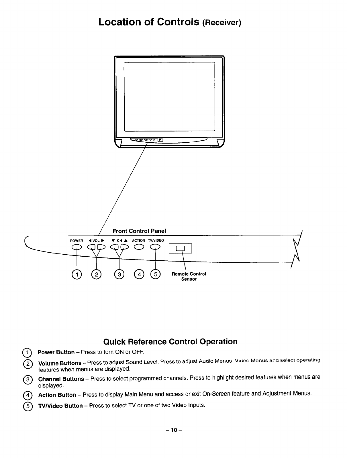
Location of Controls (Receiver)
Front Control Panel /
POWER • VOL • • CH • ACTION "IV/VIDEO
f
Control
Sensor
Quick Reference Control Operation
Q ower Button - Press to turn ON or OFF.
Q olume Buttons - Press to adjust Sound Level. Press to adjust Audio Menus, Video Menus and select operating
features when menus are displayed.
Channel Buttons - Press to select programmed channels. Press to highlight desired features when menus are
displayed.
Q ction Button - Press to display Main Menu and access or exit On-Screen feature and Adjustment Menus,
TV/Video Button - Press to select TV or one of two Video Inputs.
-10-
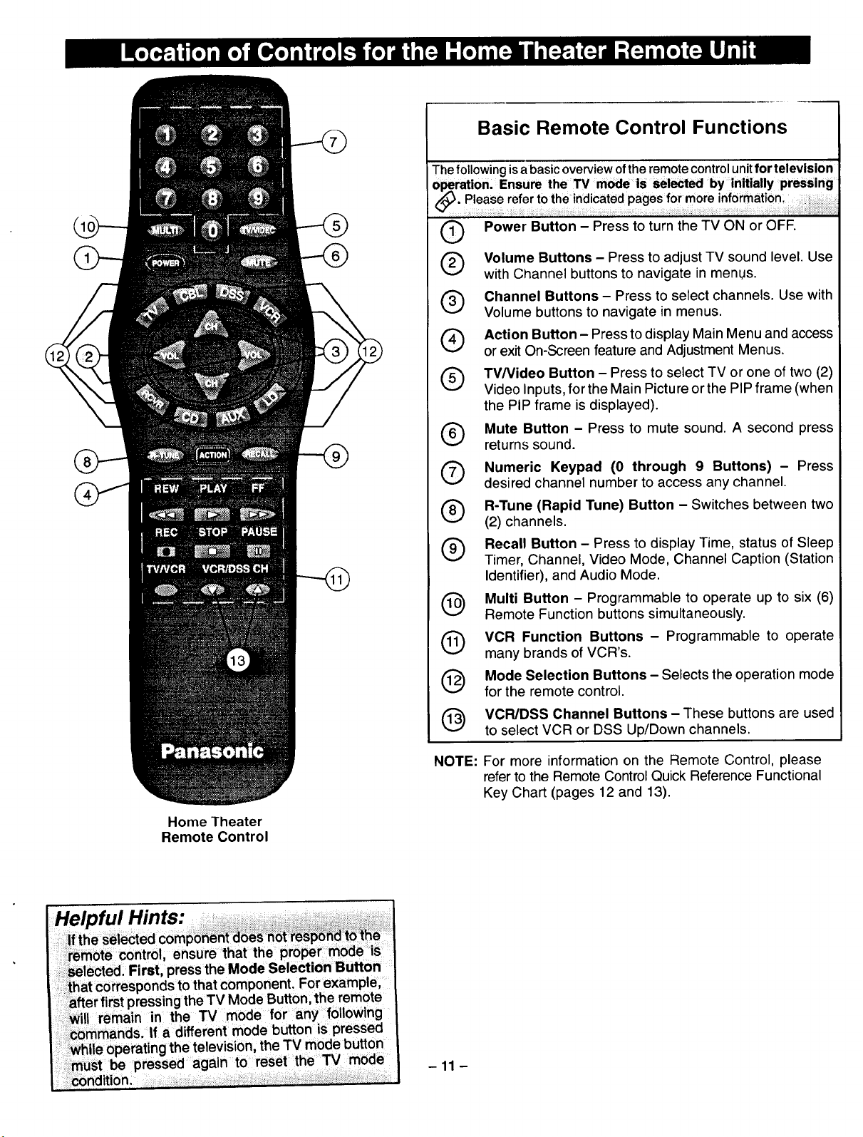
Basic Remote Control Functions
The following isa basic overview of the remote control unit for television
®
®
Power Button - Press to turn the TV ON or OFF.
Volume Buttons - Press to adjust TV sound level. Use
with Channel buttons to navigate in menus.
Channel Buttons- Press to select channels. Use with
Volume buttons to navigate in menus.
or exit On-Screen feature and Adjustment Menus.
TV/Video Button - Press to select TV or one of two (2)
Video Inputs, for the Main Pictu reor the PIP frame (when
the PIP frame is displayed).
Mute Button - Press to mute sound. A second press
returns sound.
Numeric Keypad (0 through 9 Buttons) - Press
desired channel number to access any channel.
R-Tune (Rapid Tune) Button - Switches between two
(2) channels.
Recall Button - Press to display Time, status of Sleep
Timer, Channel, Video Mode, Channel Caption (Station
Identifier), and Audio Mode.
Multi Button - Programmable to operate up to six (6)
Remote Function buttons simultaneously.
®
Q Action Button- Press to display Main Menu and access
®
®
Home Theater
Remote Control
that corresponds to that component. For example,
after first pressingthe TV Mode Button, the remote
WIll remain in the TV mode for any following
.commands. If a different mode button is pressed
_ while operating the television, the TV mode button
must be pressed again to reset the TV mode
condition ................ _. _.;_._ ......
VCR Function Buttons - Programmable to operate
many brands of VCR's.
Mode Selection Buttons- Selects the operation mode
for the remote control.
VCR/DSS Channel Buttons- These buttons are used
to select VCR or DSS Up/Down channels.
NOTE: For more information on the Remote Control, please
refer to the Remote Control Quick Reference Functional
Key Chart (pages 12 and 13).
-11 -
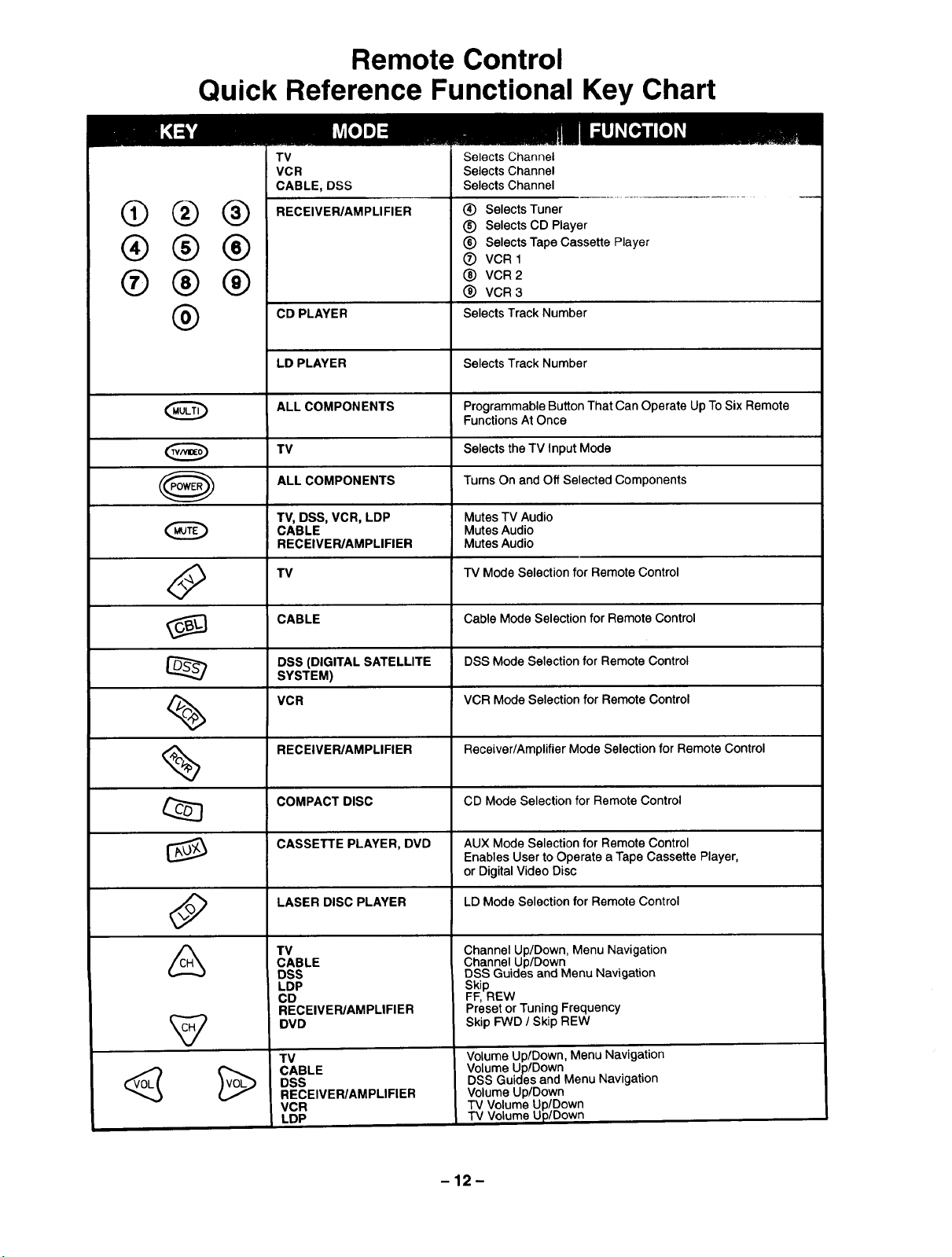
Remote Control
Quick Reference Functional Key Chart
@®®
®®®
®®®
®
TV
VCR
CABLE, DSS
RECEIVER/AMPLIFIER
CD PLAYER
LD PLAYER
ALL COMPON ENTS
TV
ALL COMPONENTS
TV, DSS, VCR, LDP
CABLE
RECEIVER/AMPLIFIER
TV
Selects Channel
Selects Channel
Selects Channel
(_) Selects Tuner
® Selects CD Player
(_) Selects Tape Cassette Player
® VCR1
(_) VCR 2
® VCR3
Selects Track Number
Selects Track Number
Programmable Button That Can Operate Up To Six Remote
Functions At Once
Selects the TV Input Mode
Turns On and Off Selected Components
Mutes TV Audio
Mutes Audio
Mutes Audio
TV Mode Selection for Remote Control
%
%
CABLE
DSS (DIGITAL SATELLITE
SYSTEM)
VCR
RECEIVER/AMPLIFIER
COMPACT DISC
CASSETTE PLAYER, DVD
LASER DISC PLAYER
TV
CABLE
DSS
LDP
CD
RECEIVER/AMPLIFIER
DVD
TV
CABLE
DSS
RECEIVER/AMPLIFIER
VCR
LDP
Cable Mode Selection for Remote Control
DSS Mode Selection for Remote Control
VCR Mode Selection for Remote Control
Receiver/Amplifier Mode Selection for Remote Control
CD Mode Selection for Remote Control
AUX Mode Selection for Remote Control
Enables User to Operate a Tape Cassette Player,
or Digital Video Disc
LD Mode Selection for Remote Control
Channel Up/Down, Menu Navigation
Channel Up/Down
DSS Guides and Menu Navigation
Skip
FF, REW
Preset or Tuning Frequency
Skip FWD / Skip REW
Volume Up/Down, Menu Navigation
Volume Up/Down
DSS Guides and Menu Navigation
Volume Up/Down
TV Volume Up/Down
TV Volume Up/Down
-12-
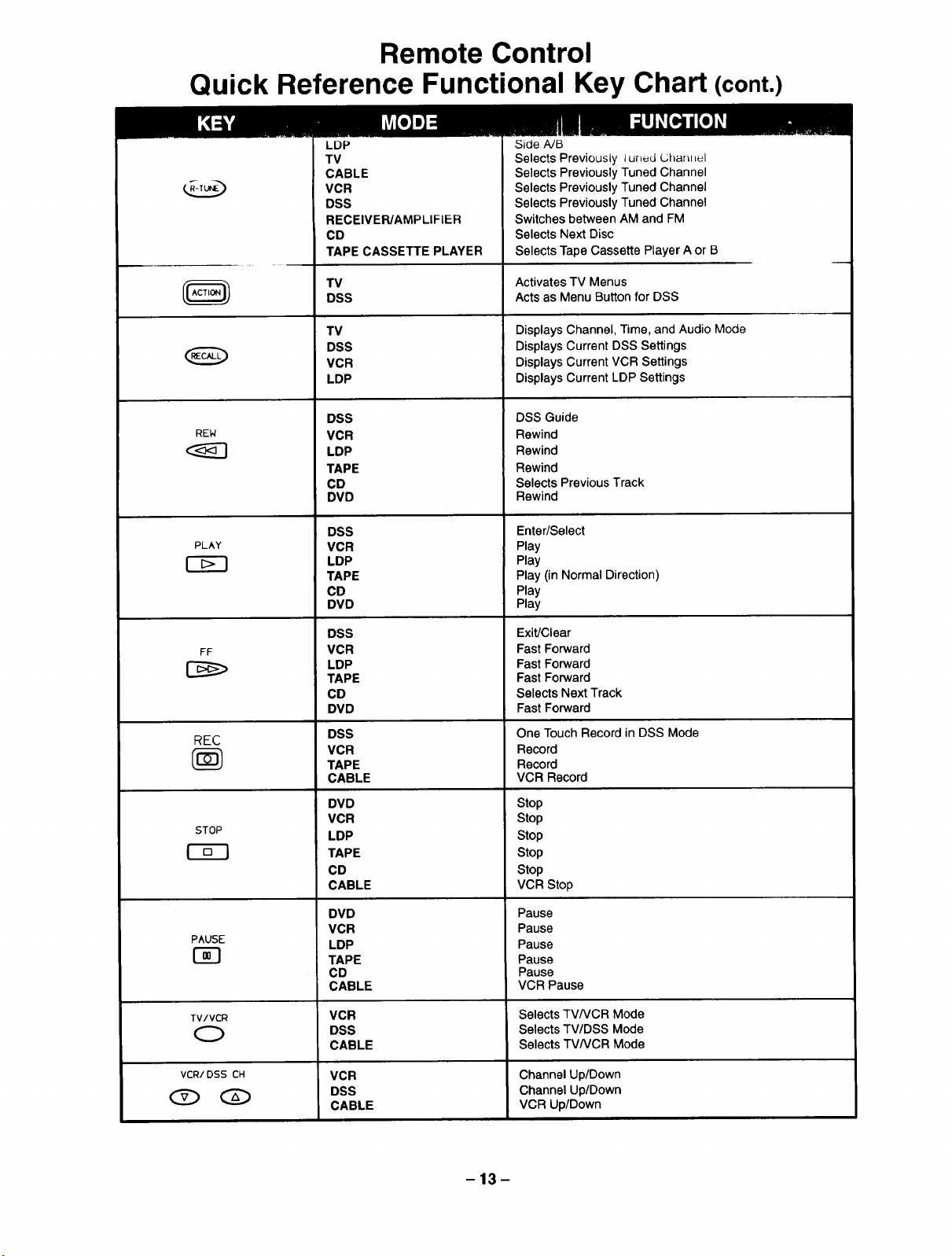
Remote Control
Quick Reference Functional Key Chart (cont.)
Q
REW
PLAY
LDP
TV
CABLE
VCR
DSS
RECEIVER/AMPLIFIER
CD
TAPE CASSETTE PLAYER
TV
DSS
TV
DSS
VCR
LDP
DSS
VCR
LDP
TAPE
CD
DVD
DSS
VCR
LDP
TAPE
CD
DVD
Side A/B
Selects Previously l uned L;hanLLuI
Selects Previously Tuned Channel
Selects Previously Tuned Channel
Selects Previously Tuned Channel
Switches between AM and FM
Selects Next Disc
Selects Tape Cassette Player A or B
Activates TV Menus
Acts as Menu Button for DSS
Displays Channel, Time, and Audio Mode
Displays Current DSS Settings
Displays Current VCR Settings
Displays Current LDP Settings
DSS Guide
Rewind
Rewind
Rewind
Selects Previous Track
Rewind
Enter/Select
Play
Play
Play (in Normal Direction)
Play
Play
FF
REC
STOP
PAUSE
TV/VCR
O
DSS
VCR
LDP
TAPE
CD
DVD
DSS
VCR
TAPE
CABLE
DVD
VCR
LDP
TAPE
CD
CABLE
DVD
VCR
LDP
TAPE
CD
CABLE
VCR
DSS
CABLE
VCR
DSS
CABLE
Exit/Clear
Fast Forward
Fast Forward
Fast Forward
Selects Next Track
Fast Forward
One Touch Record in DSS Mode
Record
Record
VCR Record
Stop
Stop
Stop
Stop
Stop
VCR Stop
Pause
Pause
Pause
Pause
Pause
VCR Pause
Selects TVNCR Mode
Selects TV/DSS Mode
Selects TVNCR Mode
Channel Up/Down
Channel Up/Down
VCR Up/Down
-13-
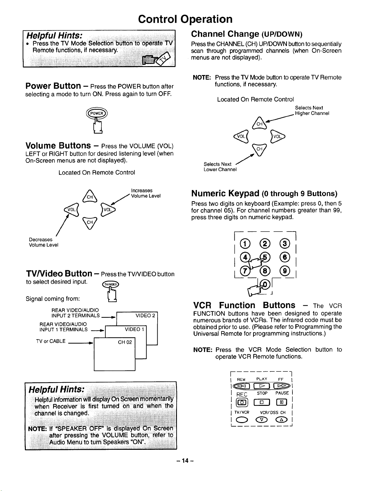
Control Operation
Channel Change (UP/DOWN)
Pressthe CHANNEL (CH) UP/DOWN buttontosequentially
scan through programmed channels (when On-Screen
menus are notdisplayed).
Power Button - Press the POWER button after
selecting a mode to turn ON. Press again to turn OFF.
Volume Buttons - Press the VOLUME (VOL)
LEFT or RIGHT button for desired listening level (when
On-Screen menus are not displayed).
Located On Remote Control
Increases
J Volume Level
#
Decreases
Volume Level
NOTE:
Press theTV Mode button to operate TV Remote
functions, if necessary.
Located On Remote Control
Selects Next
Higher Channel
Selects Next J(_
Lower Channel
Numeric Keypad (0through 9 Buttons)
Press two digits on keyboard (Example: press 0, then 5
for channel 05). For channel numbers greater than 99,
press three digits on numeric keypad.
I 1
0®® I
TV/Video Button - Press the TV/VIDEO button
to select desired input.
Signal coming from:
REAR VIDEO/AUDIO
INPUT 2 TERMINALS ._..o,, I
REAR VIDEO/AUDIO I
INPUT 1 TERMINALS _1
TV or CABLE _ I
;J
i
1
VIDEO 2 I
v,o o,II
cfi_ __J
VCR Function Buttons - The VCR
FUNCTION buttons have been designed to operate
numerous brands of VCRs. The infrared code must be
obtained prior to use. (Please refer to Programming the
Universal Remote for programming instructions.)
NOTE: Press the VCR Mode Selection button to
operate VCR Remote functions.
[ q
I REW PLAY FF 1
I REC STOP PAUSEI
Ilij r-a7 i
I I
I TV/VCR VCR/DSS CH I
I(C> <3[) C>l
I J
-14-
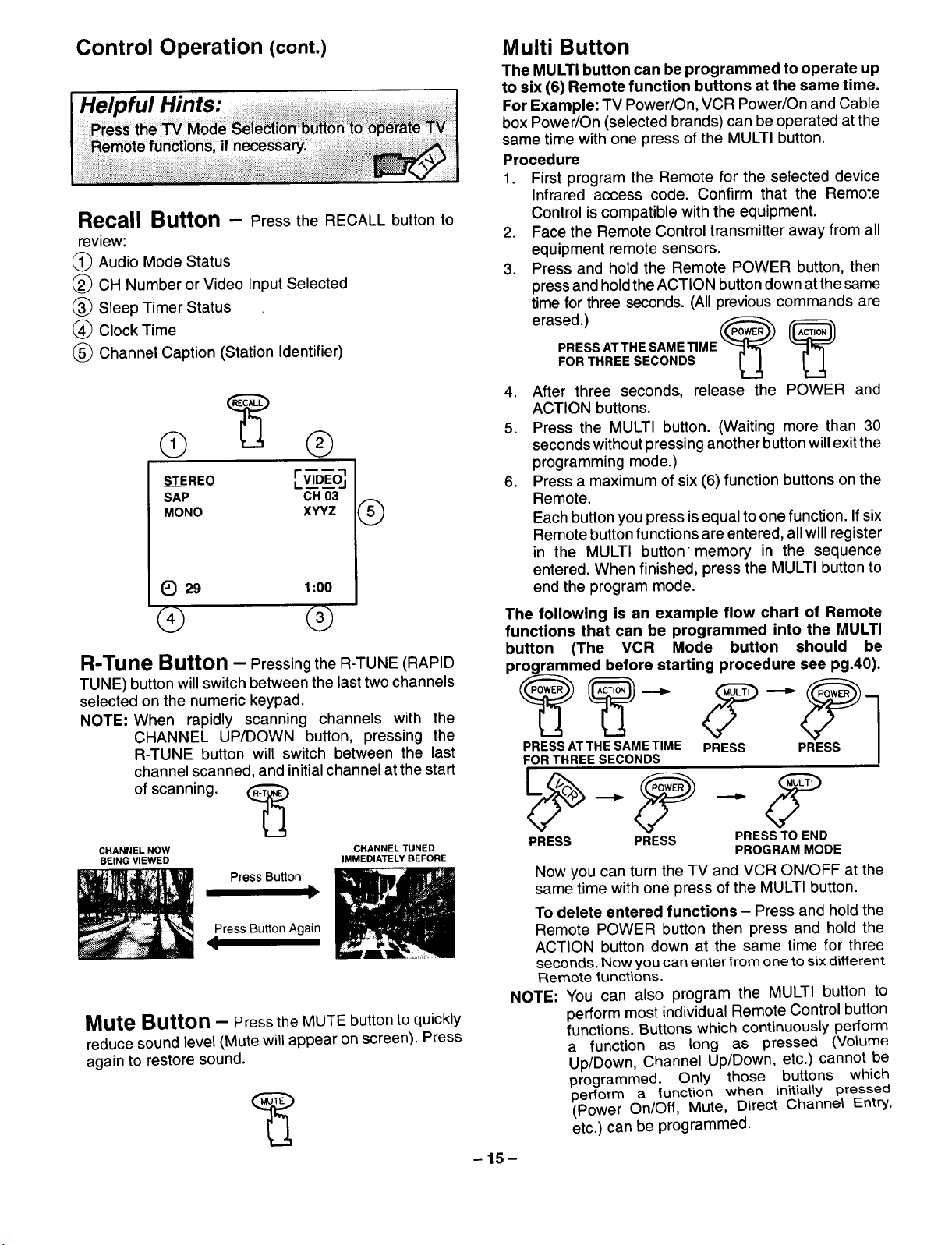
Control Operation (cont.)
Helpful Hints:
Recall Button - Press the RECALL button to
review:
(_ Audio Mode Status
(_ CH Number or Video Input Selected
(_ Sleep Timer Status
(_ Clock Time
(_ Channel Caption (Station Identifier)
SAP CH 03
MONO XYYZ
1_ 29 1:00
®
® @
R-Tune Button - Pressing the R-TUNE (RAPID
TUNE) button willswitch between the last two channels
selected on the numeric keypad.
NOTE: When rapidly scanning channels with the
CHANNEL UP/DOWN button, pressing the
R-TUNE button will switch between the last
channel scanned, and initialchannel at the start
Multi Button
The MULTI button can be programmed to operate up
to six (6) Remote function buttons at the same time.
For Example: TV Power/On, VCR Power/On and Cable
box Power/On (selected brands) can be operated at the
same time with one press of the MULTI button.
Procedure
1. First program the Remote for the selected device
Infrared access code. Confirm that the Remote
Control iscompatible with the equipment.
2. Face the Remote Control transmitter away from all
equipment remote sensors.
3. Press and hold the Remote POWER button, then
press and hold the ACTION buttondown at thesame
time for three seconds. (All previous commands are
PRESS AT THE SAME TIME ---_r_-
erased.) ,_..,_
FOR THREE SECONDS _ J,
4. After three seconds, release the POWER and
ACTION buttons.
5. Press the MULTI button. (Waiting more than 30
seconds without pressing another button will exit the
programming mode.)
6. Press a maximum of six (6) function buttons on the
Remote.
Each button you press is equal to one function. If six
Remote button functions are entered, all will register
in the MULTI button memory in the sequence
entered. When finished, press the MULTI button to
end the program mode.
The following is an example flow chart of Remote
functions that can be programmed into the MULTI
button (The VCR Mode button should be
programmed before starting procedure see pg.40).
PRESS AT THE SAME TIME PRESS PRESS
FOR THREE SECONDS
of scanning. _
CHANNELNOW CHANNEL TUNED
BEING VIEWED IMMEDIATELY BEFORE
Press Button
Press Button Again
.=
Mute Button - Press the MUTE button to quickly
reduce sound level (Mute will appear on screen). Press
again to restore sound.
PRESS PRESS PRESS TO END
Now you can turn the TV and VCR ON/OFF at the
same time with one press of the MULTI button.
To delete entered functions - Press and hold the
Remote POWER button then press and hold the
ACTION button down at the same time for three
seconds. Now you can enter from one to six different
Remote functions.
NOTE: You can also program the MULTI button to
perform most individual Remote Control button
functions. Buttons which continuously perform
a function as long as pressed (Volume
Up/Down, Channel Up/Down, etc.) cannot be
programmed. Only those buttons which
perform a function when initially pressed
(Power On/Off, Mute, Direct Channel Entry,
etc.) can be programmed.
-15-
PROGRAM MODE
 Loading...