

Panasonic CT-25G6E, CT-25G6CE, CT-25G6UE, CT-27G6E, CT-27G6DE Service Manual
...
ORDER NO. MTNC010306C1
B5
Service Manual
Color Television
Main Manual
(NA7D)
Panasonic
CT-27G6E/DE/UE
SP-2724E/UE
Models
Chassis
CT-25G6E AP361
CT-25G6CE AP361
CT-25G6UE AP361
CT-27G6E AP362
CT-27G6DE AP362
CT-27G6UE AP362
Quasar
Models
SP-2724E EC363
SP-2724UE EC363
Chassis
This Service manual is issued as a service guide for the models of the NA7D family listed above. Included are
schematics, alignment procedures, disassembly procedures, and a parts list.
“WARNING! This Service Manu al is des igned for ex perienced re pair techni cians only a nd is not designed fo r use by th e general p ublic.
It does not contain warnings or cautions to advise non-technical individuals of potential dangers in attempting to service a product.
Products powered by electricity should be se rviced or repaire d only by experienc ed professio nal techni cians. Any a ttem pt to
service or repair the product or products dealt with in this Service Manual by anyone else could result in serious injury or death.”
The service technician is required to read and follow the “Safety Precautions” and “Important Safety Notice” in this Manual.
Copyright 2001 by M atsus hita Elec tric Cor pora tion o f Amer ica. All rig hts res erve d. Un auth orize d copy ing an d dist ributio n is a vio lation of law.
Important Safety Notice
Special components are used in this television set which are important for safety. These parts are identified on the
schematic diagra m by the s ymbol and printed in BOLD TYPE on the replaceme nt part list. It is essential that
these critical parts are replaced with the manufacturer’s specified replacement part to prevent X-ray radiation,
shock, fire or other hazards. Do not modify the original design without the manufacturer’s permission.
Safety Precautions
General Guidelines
An Isolation T ransformer should always be used during
the servicing of a Receiver whose chassis is not
isolated from AC power line. Use a transformer of
adequate power rating as this protects the technician
from accidents resulting in personal injury from
electrical shocks. It will also pr otect the Receiver from
being damaged by accidenta l shorting that may occur
during servicing.
When servicing, observe the original lead dress,
especially in the high voltage circuit. Replace all
damaged parts (also parts that show signs of
overheating.)
Always Replace Protective Devices, such as fishpaper,
isolation resistors and capacitors, and shields after
servicing the Receiver. Use only manufacturer’s
recommended rating for fuses, circuits breakers, etc.
High potentials are present when this Receiver is
operating. Operation of the Receiver without the rear
cover introduc es danger for el ectrical sho ck. Servicin g
should not be performed by anyone who is not
thoroughly familiar with the necessary precautions
when servicing high-voltage equipment.
Extreme care should be p ra ctic ed wh en Handling the
Picture Tube. Rough handling may cause it to implode
due to atmospheric pres sure. (14.7 lbs per sq. in.). D o
not nick or scratch the glass or subject it to any undu e
pressure. When handling, use safety goggles and
heavy gloves for protection. Discharge the picture tube
by shorting the anode to chassis ground (not to the
cabinet or to other mounting hardware). When
discharging con nect cold ground (i .e. da g ground lead)
to the anode with a well insulated wire or use a
grounding probe.
Avoid prolonged exposure at close range to unshielded
areas of the picture tube t o prevent exposure t o X-ray
radiation.
The T est Picture Tube used for servicing the chassis at
the bench should incorporate safety glass and
magnetic shieldi ng. The safety glass pr ovide shielding
for the tube viewing area against X-ray radiation as
well as implosion. T he magnetic shield lim its the X-ray
radiation around the bell of the pict ure tube in addition
to the restricting magnetic effects. When using a
picture tube test jig for service, ensure that the jig is
capable of handling 50kV without causing X-ray
radiation.
Before returning a serviced Receiver to the owner, the
service technician must thoroughly test the unit to
ensure that is completely safe to operate. Do not use a
line isolation transformer when testing.
Leakage Current Cold Check
Unplug the AC cord and connect a jumper between the
two plug prongs.
Measure the re si stance betw e e n th e j um p ere d AC pl ug
and expose metallic parts such as screwheads,
antenna terminals, control shafts, etc. If the exposed
metallic part has a return path to the chassis, the
reading should be between 240kΩ and 5.2MΩ. If the
exposed metallic part does not have a return path to
the chassis, the reading should be infinite.
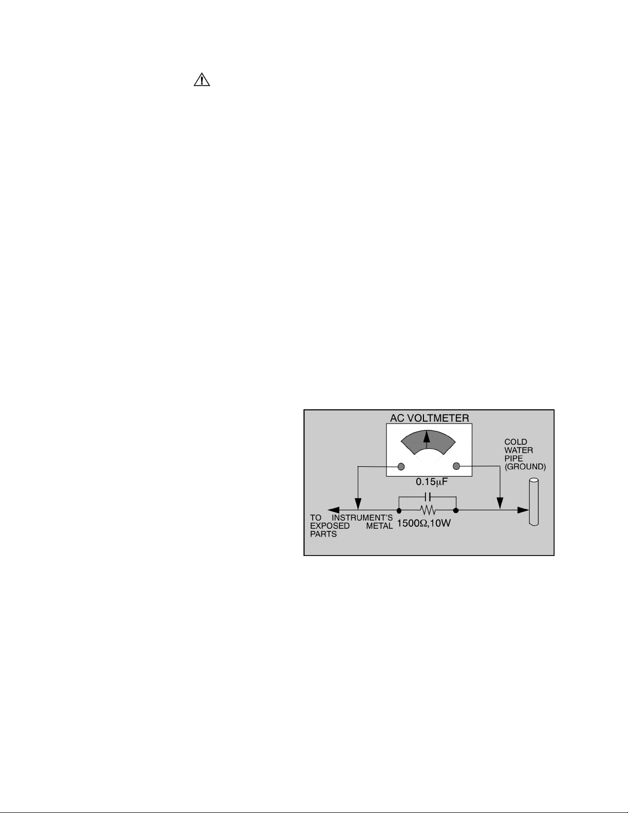
Leakage Current Hot Check (Fig. 1)
Plug the AC cord directly into the AC outlet. Do not use
an isolation transformer during the check.
Connect a 1.5kΩ 10 watt resistor in parallel with a
0.15µF capacitor between an exposed metallic part
and ground. Use earth ground, for example a
water pipe.
Using a DVM with a 1000 ohms/volt sensitivity or
higher, measure the AC potential across the resistor.
Repeat the procedure and measure the voltage
present with all other exposed metallic parts.
Verify that any potential does not exceed 0.75 volt
RMS. A leakage curr ent test er (suc h a S impson M odel
229, Sencore Model P R57 or equival ent) may be used
in the above procedure, in which case any current
measure must not exceed 0.5 milliamp. If any
measurement is out of the specified limits, there is a
possibility of a s hoc k haz ard and the Receiver mus t b e
repaired and rechecked before it is returned to the
customer.
Figure 1. Hot Check Circuit
X-ray Radiation
WARNING: The potential source of X-ray radiation in the
Receiver is in the High Voltage section and the picture
tube. Refer to “X-Ray Protection Circuit Check &
Adjustments” on page5 to confirm HHS voltage.
High Voltage (CRT Anode)
Set the brightness, picture, sharpness and color
controls to minimu m (to obtain dark image). Measure
the High Voltage. The high voltage should be
29.25kV ± 1.25kV. If the upper limit is out of toler ance,
immediate service and correction is required.
Note: It is important to use an accurate, calibrated
high voltage meter.
- 2 -

Important Safety Notice . . . . . . . . . . . . . . . . . . 2
Safety Precautions . . . . . . . . . . . . . . . . . 2
Service Notes. . . . . . . . . . . . . . . . . . . . . . . . . . . 4
X-Ray Protection Circuit Check
& Adjustments . . . . . . . . . . . . . . . . . 5
Receivers Feature Table . . . . . . . . . . . . . . . . . . 6
Location of Receiver Controls . . . . . . . . . . . . . 7
Location of Controls . . . . . . . . . . . . . . . . . . . . . 8
Service Adjustments
(Electronic Control). . . . . . . . . . . . . . . . . . 22
Sub-Contrast. . . . . . . . . . . . . . . . . . . . . 22
Sub-Brightness . . . . . . . . . . . . . . . . . . . 22
Tint/Color Adjustment . . . . . . . . . . . . . . 22
White Balance. . . . . . . . . . . . . . . . . . . . 23
Sub-Brightness Final Adjustment . . . . . 23
Horizontal Centering. . . . . . . . . . . . . . . 23
Vertical Size . . . . . . . . . . . . . . . . . . . . . 24
MTS Circuit Adjustment . . . . . . . . . . . . 24
Input Level Adjustment . . . . . . . . . . . . . 24
Stereo Separation Adjustment . . . . . . . 24
Clock Adjustment . . . . . . . . . . . . . . . . . 24
Service Adjustments
(Mechanical Controls). . . . . . . . . . . . . . . . 25
Disassembly for Service. . . . . . . . . . . . . . . . . . 9
Disassembly for CRT Replacement . . . . . . . . . 9
CRT Replacement . . . . . . . . . . . . . . . . . . . . . . . 9
Chassis Service Adjustment Procedures . . . 10
130.0V B+ Voltage Confirmation . . . . . 10
Source Voltage Chart . . . . . . . . . . . . . . 10
High Voltage Check . . . . . . . . . . . . . . . 10
Purity Convergence Procedure . . . . . . . . . . . .11
Vertical Raster Shift Adjustment. . . . . . .11
Initial Center Static Convergence . . . . . .11
Purity Adjustment . . . . . . . . . . . . . . . . . 12
Final Convergence Procedure . . . . . . . 12
Permalloy Convergence
Corrector Strip . . . . . . . . . . . . . . . . 12
Service Mode
(Electronic Controls). . . . . . . . . . . . . . . . . 14
Instructional Flow Chart
for Service Mode . . . . . . . . . . . . . . . . . . . . 20
Focus (Part of T551). . . . . . . . . . . . . . . 25
Component Identification . . . . . . . . . . . . . . . . 26
Parts List . . . . . . . . . . . . . . . . . . . . . . . . . . . . . 29
Components Abbreviations Guide. . . . . . . . . 35
Schematic Notes . . . . . . . . . . . . . . . . . . . . . . . 36
Service Mode Adjustments. . . . . . . . . . . . . . . 47
C-Board Schematic . . . . . . . . . . . . . . . . . . . . . 39
C-Board Voltages. . . . . . . . . . . . . . . . . . . . . . . 39
A-Board Schematics
CT-25G6/CE/UE. . . . . . . . . . . . . . . . . . . 40
CT-27G6E/CE/UE) . . . . . . . . . . . . . . . . . 42
SP-2724E/UE . . . . . . . . . . . . . . . . . . . . . 42
A-Board Voltages. . . . . . . . . . . . . . . . . . . . . . . 44
Waveforms . . . . . . . . . . . . . . . . . . . . . . . . . . . . 45
A & C-Boards Layouts. . . . . . . . . . . . . . . . . . . 46
- 3 -
Service Notes
Chip Components
Note: Some components may be affixed wi th glue. B e careful not to bre ak or damag e foil un der the com ponent
or at the pins of th e ICs when removing . Usually applying he at to the component for a short time while
twisting with tweezers will break the component loose.
Leadless Chip Component
(surface mount)
Chip components must be replaced with identical chips
due to critical foil tr ack spacing. There are n o holes in
the board to mount standard transistors or diodes.
Some chips capacitor or resistor board solder pads
may have holes t hrough the board, however the hole
diameter limits standard resistor replacement to 1/8
watt. Standard capacitor may also be limited for the
same reason. It is recommended that identical
components be used.
Chip resistor have a three digit numerical resistance
code - 1st and 2nd significant digits and a multiplier.
Example: 162 = 1600 or 1.6kΩ resistor, 0 = 0Ω (jumper).
Chip capacitors generally do not have the value
indicated on the capacitor. The color of the co mponent
indicates the general range of the capaci tance.
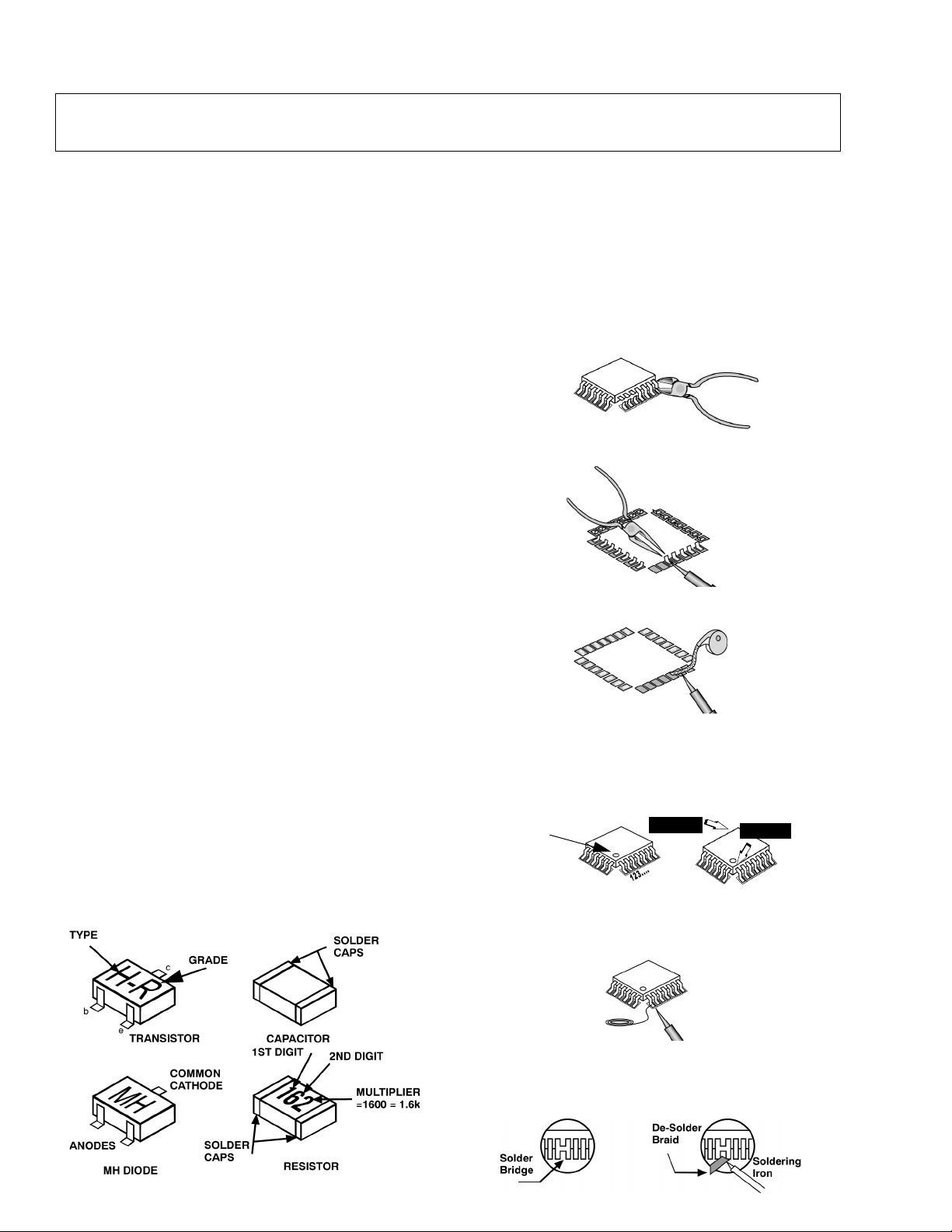
Chip transistors are id enti fie d b y a two letter code. The
first letter indicates the type and the second lette r, the
grade of transistor.
Chip diodes have a two lette r i den tif icati on c ode as per
the code chart an d are a dual diode pack with either
common anode or common cathode. Check the parts
list for correct diode number.
Component Removal
1. Use solder wick to remove s older from compo nent
end caps or terminal.
2. Without pulling up, carefully twist the component
with tweezers to break the adhesive.
3. Do not reuse removed leadless or chip
components since they are subject to stress
fracture during removal.
Chip Component Installation
1. Put a small amount of solder on the board
soldering pads.
2. Hold the chip component against the soldering
pads with tweezers or with a miniature alligator clip
and apply heat to the pad area with a 30 watt iron
until solder flows. Do not appl y heat for more than
3 seconds.
How to Replace Flat-IC
- Required Tools -
• Soldering iron • De-solder braids
• Needle nose pliers • Magnifier
• Wire cutters (sharp & small)
1. Cut the pins of a defective IC with wire cutters.
Remove IC from boar d. If IC i s glued to the board ,
heat the IC and release the IC. See Note above.
Flat IC
2. Using soldering iron and needle nose pliers
remove the IC pins from the board.
Soldering
Iron
3. Using de-soldering braid and soldering iron remove
solder from affected are on board (pads).
De-soldering
Braid
Soldering
Iron
4. Position the new Flat-I C in place (app ly the pins of
the Flat-IC to the soldering pads where the pins
need to be soldered). Determine the positions of
the soldering pads and pins by correctly aligning
the polarity symbol. Solder pin #1 first, align the IC.
Polarity
symbol
Solder the pin op posite to pin #1. This will ass ist
positioning the IC.
5. Solder all pins to the soldering pads using a fine
tipped soldering iron.
2nd solder
1st solder
Solder
6. Check with a magnifier for solder bridge between
the pins or for d r y jo int b etwe en pi ns a nd s old er in g
pads. To remove a solder bridge, u se a de-solder
braid as shown in the figure below.
- 4 -
Soldering
Iron
IMPORTANT: To protect against possible damage to
the solid state devices due to arcing or static
discharge, make certain that all ground wires and CRT
DAG wire are securely connected.
CAUTION: The power supply circuit is above earth
ground and the chassis cannot be polarized. Use an
isolation transformer when servicing the Receiver to
avoid damage to the test equipmen t or to the chassis.
Connect the test equipment to the proper ground ( ) or
( ) when servicing, or incorrect voltages will be
measured.
WARNING: This Receiver has been designed to meet
or exceed applicable safety and X-ray radiation
protection as specified by government agencies and
independent testing laboratories.
To maintain original product safety design standards
relative to X-ray radiation and shock and fire hazard,
parts indicated with the s ymbol on the schematic
must be replaced with identical parts. Order parts from
the manufacturer’s parts center using the parts
numbers shown in t his service manual, or provide the
chassis number and the part reference number.
For optimum perfo rmance and reliab ility, all other parts
should be replaced with components of identical
specification.
X-Ray Protection Circuit Check &
Adjustments
This test must be perfo rmed as final check be fore the
Receiver is returned to the customer. If voltages are
out of tolerance, immediate service and correction is
required to insure safe operation and to prevent the
possibility of premature component failure.
Equipment:
1. Isolation transformer.
2. High voltage meter.
3. Short jumper.
4. Jumper di od e ( s am e a s D82 3, PN S3L60P154004 ) .
Diode should be rated a minimum of 150V.
Procedure:
1. Connect the Receiver to an isolation transformer.
Turn Receiver ON.
2. Apply a monoscope pattern.
3. In Service Mode (see S ervi ce Mod e Sect ion in th is
manual) select register Cb.
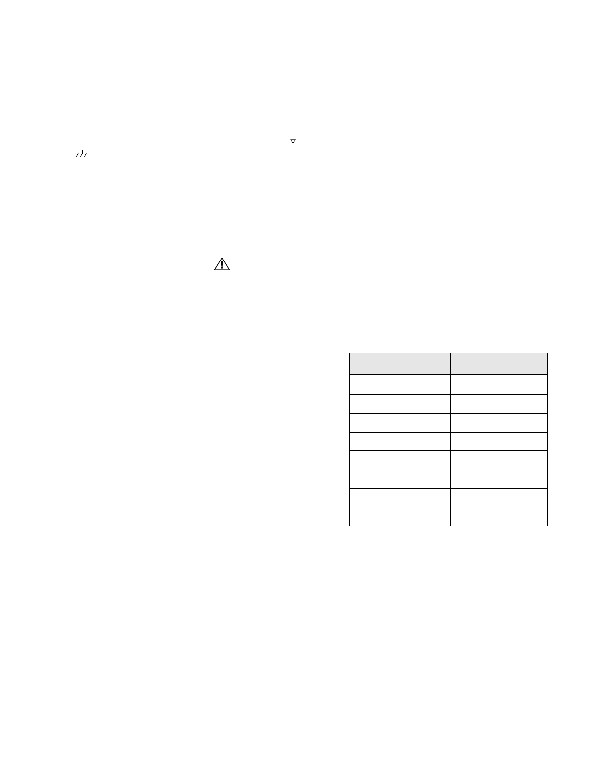
4. Measure TP5 (located near the tuner). Compare
the measured value to the left column of the table
below. Set Cb with value from the right column
corresponding to the measured level at TP5.
Example, if the measured level at TP5 is 1.03V , set
Cb to 03.
TP5 MEASUREMENT SET Cb TO (HEX)
0 ~ 0.93V 00
0.93 ~ 0.97V 01
0.97 ~ 1.01V 02
1.01 ~ 1.05V 03
1.05 ~ 1.09V 04
1.09 ~ 1.13V 05
1.13 ~ 1.17V 06
1.17 ~ 1.21V 07
5. Exit Service Mode and shut it OFF.
6. Connect the short jumper between TPD16 and
TPD17.
7. Connect the jumper diode between TPD14 and
TPD15 (cathode connected to TPD14, anode
connected to TPD15, See Fig. 4 for locations).
8. Apply 75VAC to the input of the isolation
transformer.
9. Turn Receiver ON.
10. Set PICTURE and BRIGHTNESS to minimum.
11. Slowly increase the voltage at the input of the
isolation transformer and confirm HHS voltage
measure 35.0KV for 25” models, 35.8KV for 27”
models using SAMSUNG CRT or 35.0KV for 27”
models using AMEC CRT when the Receiver starts
to go out of sync.
12. Turn Receiver OFF and remove jumper & diode.
- 5 -
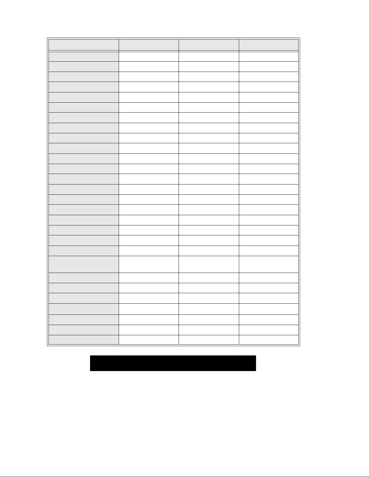
Receiver Feature Table
FEATURE\MODEL CT-25G6E/CE/UE CT-27G6E/DE/UE SP-2724E/UE
Chassis AP361 AP362 EC363
Tuning system 40K 40K 40K
# of channels 181 181 181
Menu language Eng/Span/Fr Eng/Span/Fr Eng/Span/Fr
Closed Caption XXX
V-Chip XXX
75 Ω input XXX
FM radio XN/AN/A
Remote Model # EUR501455 EUR501450 EUR511514
Picture tube A63QDB891X A68QDN891X M68LGL061X
Panablack Tube XXX
Comb Filter 2 Line Digital 2 Line Digital 2 Line Digital
V/A norm VVV
MTS/SAP/DBX XXX
AI Sound XXX
Built-in audio power 1.5W x 2 (10%) 1.5W x 2 (10%) 1.5W x 2 (10%)
# of speakers 222
A/V in (rear/front) 1 (1 / 1) 1 (1 / 0) 1 (1 / 0)
S-VHS input (rear/front) N/A 1/0 1/0
Headphone Jack XXN/A
Dimensions mm
(WxDxH) in
Weight (kg/lbs) 29 / 63.8 35 / 77.2 35 / 77.2
Power source (V/Hz) 120 / 60 120 / 60 120 / 60
Anode voltage 29.25kV ± 1.25kV 29.25kV ± 1.25kV 29.25kV ± 1.25kV
Video input jack
Audio input jack 500mV RMS 47kΩ 500mV RMS 47kΩ 500mV RMS 47kΩ
A-Board TNP2AH024 CB* BB* BH*
C-Board TNP2AA075 AC* AB* AG*
633.4 x 491.8 x 568
24.9 x 19.4 x 22.4
75Ω, phono jack 1V
1V
p-p
665.2 x 545 x 594.8
26.2 x 21.5 x 23.4
75Ω, phono jack 1V
p-p
731 x 684 x 614
28.8 x 26.9 x 24.2
75Ω, phono jack
p-p
Table 1. Receiver Features
Specifications are subject to change without notice or obligation.
Dimensions and weights are approximate.
* Note: When ordering a replacement board assembly,
append an “S” to the board number.
Example: to order the A-Board for CT-27G6E, the
replacement board is TNP2AH024BBS.
- 6 -
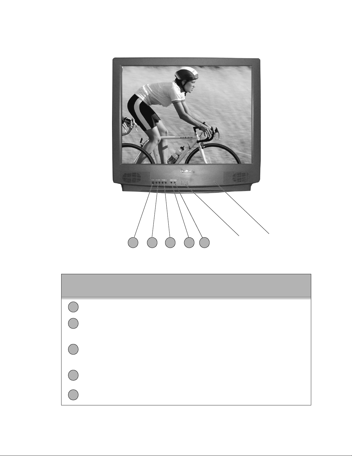
Location of Receiver Controls
1
32
4 5
Remote Control
Sensor
Front A/V Input
(Available on
some models)
Figure 2. Location of Controls (Quasar models displayed, Panasonic models vary).
Quick Reference
Control Operation
1
Power Button - Press to turn ON or OFF.
Volu me B uttons - Press to adjust Sound Level, or to adjust Audio Menus, Video
2
Menus, and select operating features when menus are displayed
Channel Buttons - Press to select programmed chan nels. Press to highlight des ired
features when menus are dis played. Also use to s elect Cable Conver ter box c hannel s
3
after programming R emote Control Infra-red code s (the TV/AUX/CABLE swi tch must
be set in CABLE position).
Action Button - Press to display Main Menu and access On Screen feature and
4
Adjustment Menus.
5
TV/Video Button - Press to select TV or Video Input.
- 7 -
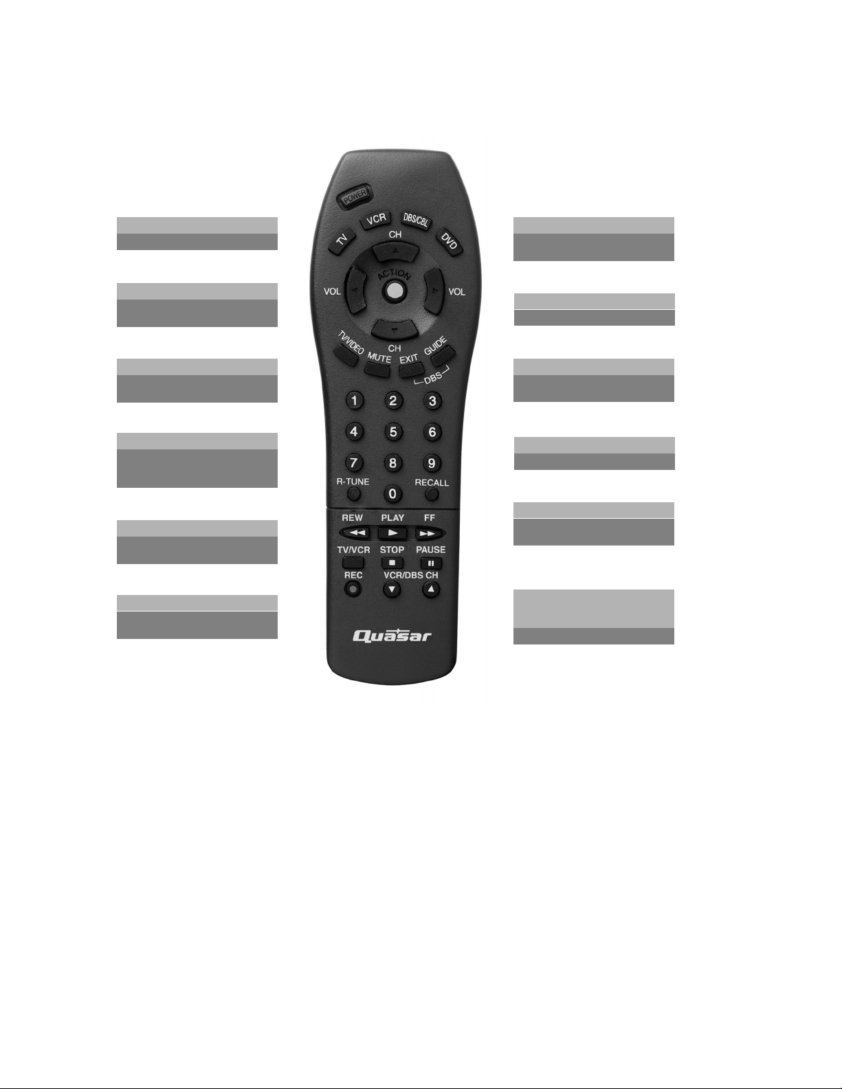
Location of Controls
POWER
Press to turn ON and OFF.
TV/VIDEO
Press to select TV or Video
Mode.
VOL
Press to adjust TV sound and
navigate in menus.
MUTE
Press to mute sound. Press to
access and cancel (CC) Closed
Caption.
“0”~ “9”
Press numeric keypad to select
any channel.
R-TUNE
Press to switch to previously
viewed channel or video mode.
TV, VCR, DBS/CBL, DVD
Press to select remote
operation.
EXIT/GUIDE
DBS function buttons.
CH
Press to select next channel
and navigate in menus.
ACTION
Press to access menus.
RECALL
Press to display time, channel,
sleep timer, and other options.
REW, PLAY, FF, TV/VCR,
STOP, PAUSE, REC,
VCR/DBS CH
Component function buttons.
EUR511514
(Typical)
Figure 3. Location of Controls (Quasar models, Panasonic remotes vary).
- 8 -

Disassembly for Service
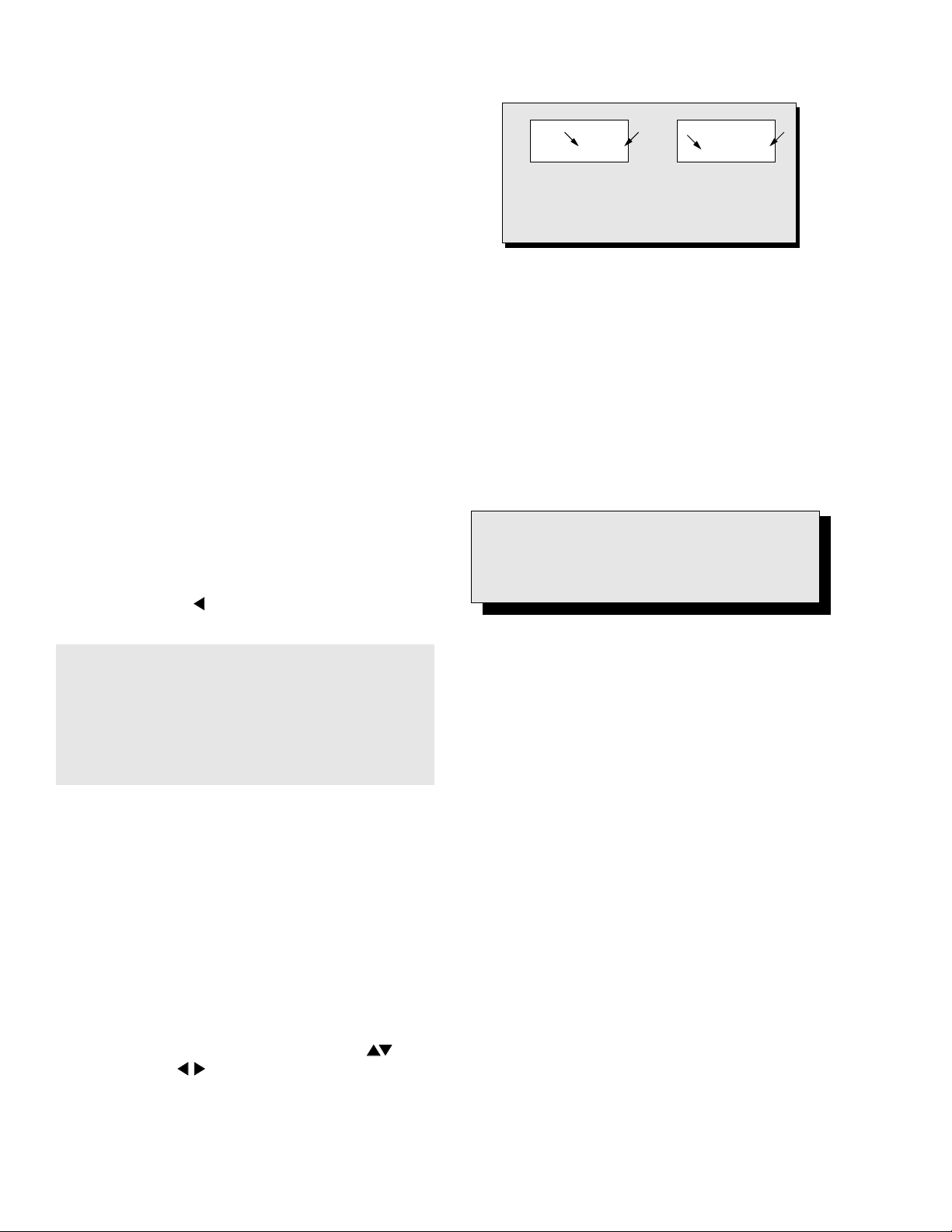
Back Cover
Remove all the screws marked with an arrow( )
from the back of the Receiver.
Note: Screw configuration, type, and number of
screws vary depending on the model of the
Receiver serviced; various models are covered
in this Manual. Reuse hardware when
reassembling the Receiver.
• 3 screws at the top edge of the Receiver.
• 1 screw at each lower corner of the Receiver.
• 1 screw by the AC cord assembly.
• 1 screw by the A/V jacks.
• 1 screw by the Flyback assembly.
A-Board - Main Chassis
1. Slide the chassis completely out of the guide rails.
2. Stand the Receiver on its edge. The undersi de of
the board is completely accessible for component
replacement.
Note: Some tie-wraps t hat secure the wire d ressings
may need to be unfastened for chassis
removal.
C-Board - CRT Output
The board plugs onto the socket on the CRT neck.
To release the Focus wire, use a dull object to
release the tab on the socket (near the wire
opening) and carefully pu ll on the wi re. To connect
the Focus wire, press on the tab to lock it then
insert the wire in the opening and press on it until it
is fully inserted and locked in place.
Speakers
Each speaker is secured to the cabinet’s front with
2 screws.
Keyboard Push Button Assembly
Fastened with screws to the inside of the cabinet
front.
Disassembly for CRT Replacement
1. Discharge the CRT as instructed in the Safety
Precautions (see page 2).
2. Disconnect the yoke (DY) plug, degaussing coil
(DEG) plug from the main board.
3. Unplug the CRT 2nd anode button from the main
board.
4. Remove the C-Board from the CRT base and
unplug the black wire (CRT dag ground) C10.
5. Disconnect the A11, A12, and Speakers plugs from
the A-Board.
6. Lift the Main Chassis (A-Board) and all mounted
boards complet ely o ut w ith th e CR T Bo ard a tt ached .
CRT Replacement
1. Perform Disassembly for CRT Replacement
procedure.
2. Insure that the CRT H.V. Anode button is
discharged before handling the CRT. Read the
Safety Precautions (see page 2 on handling the
picture tube.)
3. Remove the components from the CRT neck an d
place the cabinet face down on a soft pad.
4. Note the original order for the CRT mounting
hardware as they are remove from the CRT
mounting brackets at each corner of the CRT.
5. Remove the CRT with the deg aussing coil and th e
dag ground braid attached.
6. Note the original locations and mounting of the
degaussing coil and the dag ground assembly to
insure proper reinstallation on the replacement
CRT.
To remove and re-mount the degaussing coil: The
degaussing coil is held in place by clampers
fastened to the CRT corner ears. These clampers
must be installed onto th e replacement CRT prior
to mounting the degaussing coil.
To remove and re-mount the dag ground braid:
a. Unhook the coil spring from the bottom corners
of the CRT ears.
b. Releas e the braid loop from the upper corne rs
of the CRT ears.
7. Mount the dag ground braid on the replacement
CRT. Position the degaussing coil with new ties.
Dress coil as was on the original CRT.
8. Replace the components on CRT neck and
reinstall into cabinet. Verify that all ground wires
and circuit board plugs get connected.
- 9 -
Chassis Service Adjustment Procedures
All service adjustm ents are factory preset and should
not require adjustment unless controls and/or
associated components are replaced.
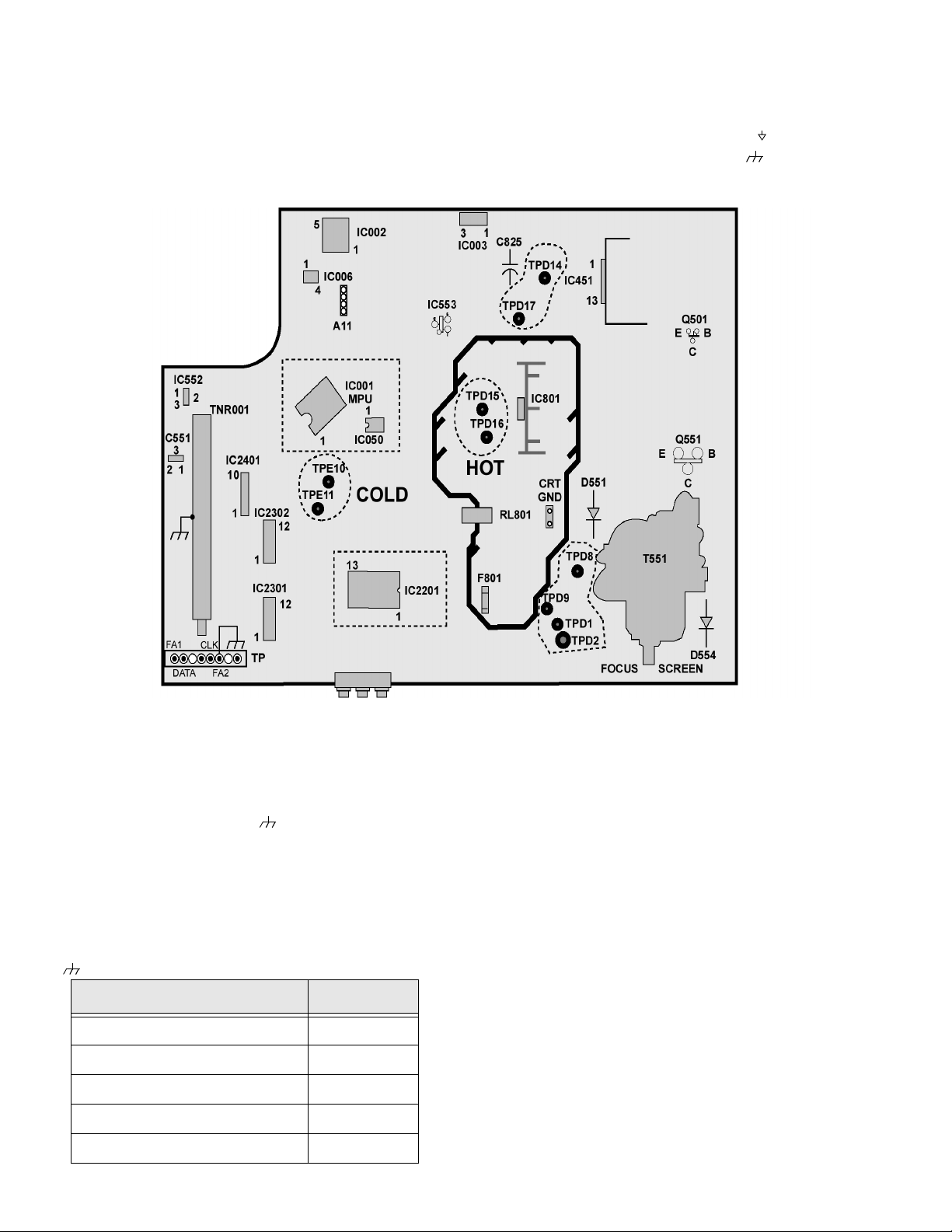
Figure 4. A-Board Main
Components and Test Points
(Components within dotted
areas are located on
trace side)
Note: Connect the (-) lead of the voltmeter to the
appropriate ground. Use IC801’s heat sink
when the HOT ground symbol ( ) is used.
Otherwise, use COLD ground ( ) — Tuner
shield, IC451’s heat sink or FA2.
MOMENTARILY CONNECT A JUMPER TO ENTER SERVICE MODE (FA1 to FA2)
130.0V B+ Voltage Confirmation
1. Set the Bright and the Contrast to Minimum by
using the Picture Menu.
2. Connect the DVM between C825 (+ side) or
TPD14 and cold ground ( ).
3. Confirm that B+ voltage is 130.0V ± 2.5V. This
voltage supplies B+ to the Horizontal Output &
Flyback circuits.
Source Voltage Chart
120V AC line input. Se t the Bright and the Picture to
Minimum by using th e Picture Menu. Use cold ground
(
) for the (-) lead of the DVM.
LOCATION VOLTAGE
TPD8 26.0V ± 2.0V
TPD9 13.0V ± 2.0V
IC551 Pin3 9.0V ± 0.25V
IC552 Pin3 5.0V ± 0.25V
D554 Cathode 220V ± 15V
Adjust Picture Menu for normalized video adjustments.
High Voltage Check
1. Select an active TV channel and confirm that
horizont al is in sync.
2. Adjust Brightne ss and Contrast using P icture Icon
menu so video just disappears.
3. Confirm B+ 131V is within limit.
4. Using a high voltage meter confirm that the High
Voltage is 29.25kV ± 1.25kV.
- 10 -
Purity and Convergence Procedure
Adjustment is necessary only if the CRT or the
deflection yoke is replaced or if the setting was
disturbed. The complete procedure consists of:
1. Vertical Raster Shift Adjustment. (Only for Models
with Purity/Convergence Assembly with 4 Pairs of
Rings).
2. Initial static convergence.
3. Setting the purity.
4. Final static convergence.
results, note part numb er and look fo r specif ications a t
Service Center)
When the CRT or the Yoke is Replaced
Place the yoke on the CRT neck (do not tighten
the clamp).
For a 2-piece assembly (see Fig. 5):
Position purity/convergence assembly as shown and
tighten clamp snugly. Remove the hot-melt glue seal
on assembly and position like tabs of purity device
together at 12 o’clock to reduce its magnetic field
effect.
Figure 5. Posi tionin g o f Pur ity/Con ve rgence As semb ly
(2-piece assembly)
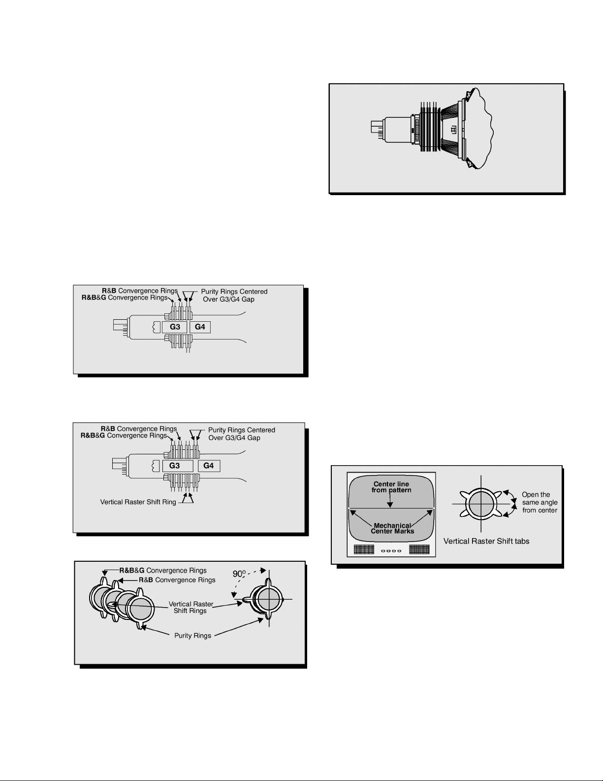
For models using 4 pairs of rings, place the vertical
raster shift tabs at 3 o’clock (90
convergence tabs, see Fig. 6 and Fig. 7)
o
from the purity and
.
Figure 8. Positioning of Purity/Convergence
Assembly (1-pi ece assembly)
For either assemblies:
Turn the Receiver ON. Operate the Receiver for 60
minutes using the first Purity Check field (white screen)
to stabilize the CRT.
Fully degauss the Receiver by using an external
degaussing coil.
Slide the defle ction y oke back and forth o n t he ne ck o f
the CRT until it produces a near white, uniform raster.
Vertical Raster Shift Adjustment (Only for
Models with Purity/Convergence Assembly with 4 Pairs
of Rings).
Apply a green pattern with a horizontal line, adjus t the
Deflection Yoke so that has no tilt, then secure it.
Adjust center line of the pattern with the mechanical
center of the CRT, this center is determined by two
marks at the side edges of the screen. To adjust the
line, once the vertical raster shift tabs are place at 3
o’clock to reduce its magnetic field effect (see Fig. 6
and Fig. 7) open the tabs the same angle from the
center, until the center line of the pattern becomes a
straight line, center ed with the marks of the CRT. (see
Fig. 9.)
Figure 6. Positioning of Purity/Convergence
Assembly (4 Pairs of Rings)
Figure 7. Positioning of Purity/Convergence
Assembly (4 Pairs of Rings)
For a 1-piece assembly (see Fig.8):
Position like tabs of purity devices together at 12
o’clock to reduce any ma gnetic field effect. (For be tter
Figure 9. Vertic a l R a s t e r S hift Adjustmen t
(4 pairs of rings assembly)
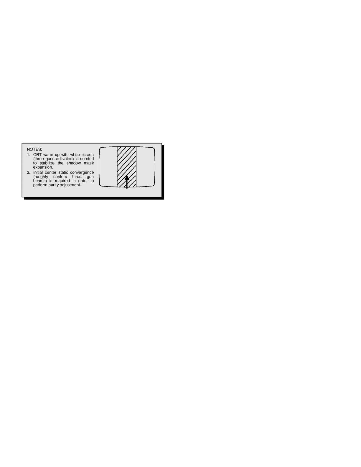
Initial Center Static Convergence
Connect a dot/cross hatch generator to the Receiver
and tune in a signal. Observe misconvergence at
center of the screen only.
Adjust the R & B pole magne ts; by se parating tab s an d
rotating to converge blue with red.
Adjust the R & B and R & B & G pole magnets: by
separating tabs and rotating to converge blue an d red
(magenta) with green.
Note: Precise convergence at this point is
not important.
- 11 -
Purity Adjustment
Figure 10. Green Raster Adjustment
When the Receiver is in the Service Mode fo r making
electronic adjustments, press the Rec all button on the
Remote Control to enter Purity Check. (See the
Service Adjustments Electronic Controls procedure).
Operate the Receiver for 60 minutes using the first
Purity Check field (white screen) to stabilize the CRT.
Fully degauss the Receiver by using an external
degaussing coil.
Press the Recall button on the Remote Control again
until the Purity Check (green screen) appears.
For a 2-piece assembl y (see Fig. 5):
Loosen the deflection yok e clamp screw an d move the
deflection yoke bac k as close to the purity magnet as
possible.
Adjust the Purity r ings to set the vertical green ra ster
precisely at the center of the screen (see Fig. 10).
Slowly move the deflecti on yoke forward until the bes t
overall green screen is displayed.
Final Convergence Procedure (see Fig. 11
through Fig. 13)
Note: Vertical size and focus adjustments must be
completed prior to performing the convergence
adjustment. Connect a dot pattern generator to
the Receiver. The Brightness level should not
be higher than necessary to obtain a
clear pattern.
Converge the red and the blue dots at the center of the
screen by rotating the R & B pole Static Convergence
Magnets.
Align The conver ged red/blue do ts with the green dots
at the center of the scree n by rotating the R & B & G
pole Static Convergence Magnets. Melt wax with
soldering iron to reseal the magnets.
Slightly tilt vertica lly and ho rizo ntally (do no t rotate) th e
deflection yoke to obtain a good overall convergence.
If convergence is not reached at the edges, insert
permalloy (see fo llowing section) from the DY corners
to achieve proper convergence. Recheck for purity and
readjust if necessary.
After vertical adjustment of the yoke, insert wedge at 11
o’clock position, then make the horizontal tilt
adjustment.
Secure the deflection yoke by inserting two side
wedges at 3 and 7 o’clock positions.
Apply adhesive between tab (thin portion) of wedge
and CRT and place tape over the tab to sec ure to the
CRT.
:
For a 1-piece assembl y (see Fig. 8):
Slowly move the deflection yoke and purity rings
assembly toward the CRT board and adju st the purity
magnet rings to set vertical green raster at center of
screen (see Fig. 10).
Gradually move the deflection yoke & purity rings
forward and adjust for best overall green screen.
Continue from here for either assemblies:
Tighten the deflection yoke clamp screw.
Press the Recall button on the Remote Control again
until the purity check (blue screen) and (red screen)
appear and observe that good purity is obtained on
each respective field.
Press the Recall button on the Remote Control again
until Purity check (white s creen) appear s. Observe th e
screen for uniform white. If purity has not been
achieved, repeat the above procedure.
Permalloy Convergence Corrector St rip (Part
No. 0FMK014ZZ)
This strip is used in some sets to match the yo ke and
CRT for optimum convergence. If t he yoke or CRT is
replaced, the strip may not be required.
First converge the set without the strip and observe the
corners.
If correction is needed:
1. Place strip between CRT and yoke, in quadrant
needing correction. Slowly move it around for
desired results.
2. Press adhesive tightly to the CRT and secure
with tape.
- 12 -
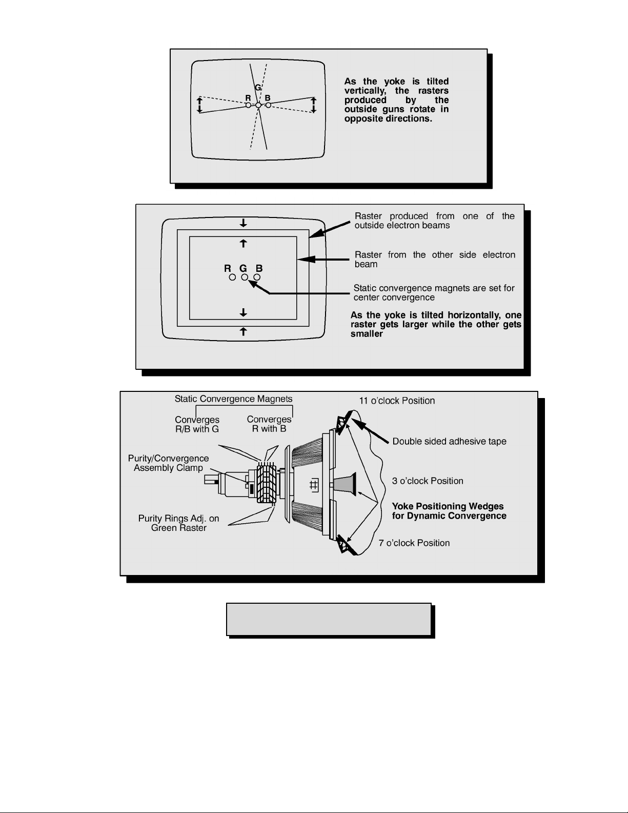
Figure 11. Vertical Yoke Movement
Figure 12. Horizontal Yoke Movement
Figure 13. Convergence Magnets and Wedges Location
Note: For models using 4 pairs of rings
assemblies see Fig. 6 for details
- 13 -
Service Mode (Electronic Controls)
This Receiver has electronic technology usi ng the I²C
Bus Concept. It performs as a control function and it
replaces many mechanical controls. Instead of
adjusting mechanical controls indivi dually, many of the
control functions are now performed by using “On
Screen Display Menu”. (The Service Adjustment
Mode.)
Note: It is sug geste d that the tec hnician r eads al l the
way through and understand the following
procedure for Entering/Exiting the Service
Adjustment Mode; then proceed with the
instructions working with the Receiver. When
becoming familiar with the procedure, the Flow
Chart for Service Mode may be used as a
quick guide.
Quick Entry to Service Mode:
At times when minor adjustments need to be done to
the electronic controls, the method of Entering the
service Mode without rem ov al of the ca bin e t ba ck is as
follows using the Remote Control:
1. Adjust VOLUME to minimum (0).
2. Set CC Mode (Close Caption) OFF.
3. Select SET-UP icon and select CABLE mode.
4. Select TIMER icon and set S LEEP time for 30, 60
or 90 Min.
5. Press ACTION button twice to exit menus.
6. Tune to the Channel 124.
7. Press the VOL button (decrease) on Receiver.
Red “CHK” appears in the left upper corner.
b
B 00 33
An address Menu appears in the right
hand corner of the screen
a
b
C 00 0 255
a
Figure 14. Service Mode Menu Adjustments.
Note: Only the applicable settings for the Receiver
serviced will be available (See a in Fig. 14).
Exiting the Service Mode:
Press the Action and the Power buttons on the
Receiver simultaneously for at least 2 seconds.
THE RECEIVER EXITS SERVICE MODE
The Receiver momentarily shuts off; then comes back
on tuned to channel 3 with a preset level of sound.
Any programmed c hannel s, ch annels capt ion data an d
some others user defined settings will be erased.
IMPORTANT
Always Exit the Service Mode
Following Adjustments.
To toggle between Aging and Service
modes:
While the “CHK” is displayed on the left top corner of
the CRT, pressing the Action and the Volume Up
buttons on the Receiver simultaneously will toggle
between the modes. Red “CHK” for Service and
yellow “CHK” for Aging.
Note: Three additional indic ators appear on screen.
One is the five digit usage in hours and the
other two are four digits for V-Chip Main and
Child ratings. Indicators are hexadecimal
numbers.
8. Press the Power Button on the Remote Control to
select one of seven Service Adjustment Modes.
1. B= Service VCJ SUB-DATA adjustments.
2. C= Service VCJ CUT-OFF adjustments.
3. M= Service MTS adjustments.
4. P= Service VCJ adjustments.
5. S= Service OPTIONS (PICTURE) adjustments.
6. X = Service AFC adjustments.
7. “CHK” = Normal operation of CHANNEL and
VOLUME .
- 14 -
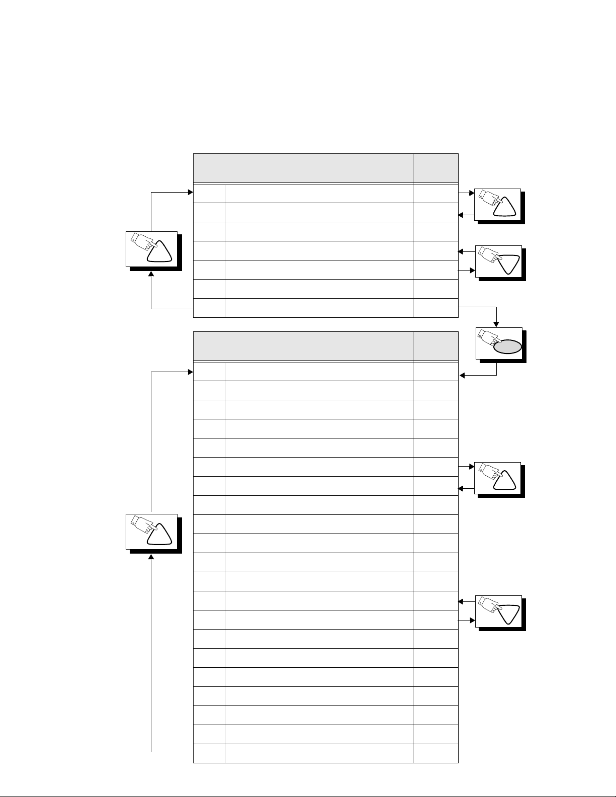
Press the POWER Button on the Remote Control to select the Service Adjustment.
CH
CH
For Adjustments:
1.Press Channel Up/Down on the
Remote Control to select one of
the available Ser vice Adjustments
(a in Fig. 14).
Note: Write Down the original
value set (b in
Fig. 14
) for
each address before
modifying anything. It is
easy to erroneously adjust
the wrong item.
2.Press Volume Up/Down on the
Remote Control to adjust the
level of the selected Service
Adjustment (b in Fig. 14).
Sub-Data Adjustment
B0 SUB-COLOR 33
B1 SUB-TINT 36
B2 SUB-BRIGHTNESS 127
B3 SUB-CONTRAST 20
B4 R OFFSET-factory preset 0
B5 YNR-factory preset 0
B6 YNR LIM-factory preset 0
Cut-Off Adjustment
C0 CUT-OFF R 0 255
C1 CUT-OFF G 0 255
C2 CUT-OFF B 0 255
C3 R DRIVE 80
C4 G DRIVE 80
Default
Level
Default
Level
CH
CH
PW
C5 B DRIVE 80
C6 V-SIZE 127
C7 NOT USED -C8 NOT USED --
C9 H CENTER 16
CA ACL 1
CB HHS 0
CC OSD SHIFT-factory preset 88
CD A CL-R EF-fa cto r y pres et 74
CE ACL-REF-fa cto ry pres et 64
CF ACL-REF-factory pres et 48
C10 ACL-REF-factory preset 40
C11 ACL-REF-factory pres et 31
C12 ACL-REF-factory preset 20
C13 ACL-COEF-factory preset 124
C14 ACL-COEF-factory preset 117
CH
CH
Note: Registers noted
with “factory
preset” should not
be modified.
- 15 -
 Loading...