

Panasonic CT-27D10B, CT-27D10UB, CT-27D10DB Service Manual
ORDER NO. MTNC000417C1
B5
Color Television
Main Manual
(NA8)
Panasonic
Models
Chassis
CT-27D10B AP338
CT-27D10UB AP338
CT-27D10DB AP338
This Service manual is issued as a service guide for the models of the NA8 family listed above. Included in this
manual are a set of schematic, block diagrams, functional descriptions, alignment procedures, disassembly
procedures, and a complete parts list.
“WARNING! This Service Manual is designed for experienced repair technicians only and is not designed for use by the general public.
It does not contain warnings or cautions to advise non-technical individuals of potential dangers in attempting to service a product.
Products powered by electricity should be serviced or repaired only by experienced professional technicians. Any attempt to
service or repair the product or products dealt with in this Service Manual by anyone else could result in serious injury or death.”
The service technician is required to read and follow the “Safety Precautions” and “Important Safety Notice” in this Main Manual.
Copyright 2000 by Matsushita Electric Corporation of
America. All rights reserved. Unauthorized copying
®
and distribution is a violation of law.
Important Safety Notice
Special components are used in this television set which are important for safety. These parts are identified on the
schematic diagram by the symbol and printed in BOLD TYPE on the replacement part list. It is essential that
these critical parts are replaced with the manufacturer’s specified replacement part to prevent X-ray radiation,
shock, fire or other hazards. Do not modify the original design without the manufacturer’s permission.
Safety Precautions
General Guidelines
An Isolation Transformer should always be used
during the servicing of a receiver whose chassis is not
isolated from AC power line. Use a transformer of
adequate power rating as this protects the technician
from accidents resulting in personal injury from
electrical shocks. It will also protect the Receiver from
being damaged by accidental shorting that may occur
during servicing.
When servicing, observe the original lead dress,
especially in the high voltage circuit. Replace all
damaged parts (also parts that show signs of
overheating.)
Always Replace Protective Devices, such as
fishpaper, isolation resistors and capacitors, and
shields after servicing the Receiver. Use only
manufacturer’s recommended rating for fuses, circuits
breakers, etc.
High potentials are present when this Receiver is
operating. Operation of the Receiver without the rear
cover introduces danger for electrical shock. Servicing
should not be performed by anyone who is not
thoroughly familiar with the necessary precautions
when servicing high-voltage equipment.
Extreme care should be practiced when Handling the
Picture Tube. Rough handling may cause it to implode
due to atmospheric pressure. (14.7 lbs per sq. in.). Do
not nick or scratch the glass or subject it to any undue
pressure. When handling, use safety goggles and
heavy gloves for protection. Discharge the picture
tube by shorting the anode to chassis ground (not to
the cabinet or to other mounting hardware). When
discharging connect cold ground (i.e. dag ground lead)
to the anode with a well insulated wire or use a
grounding probe.
Avoid prolonged exposure at close range to unshielded
areas of the picture tube to prevent exposure to Xray radiation.
The Test Picture Tube used for servicing the chassis
at the bench should incorporate safety glass and
magnetic shielding. The safety glass provide shielding
for the tube viewing area against X-ray radiation as
well as implosion. The magnetic shield limits the X-ray
radiation around the bell of the picture tube in addition
to the restricting magnetic effects. When using a
picture tube test jig for service, ensure that the jig is
capable of handling 40kV without causing Xray radiation.
Before returning a serviced receiver to the owner,
the service technician must thoroughly test the unit to
ensure that is completely safe to operate. Do not use a
line isolation transformer when testing.
Leakage Current Cold Check
Unplug the AC cord and connect a jumper between the
two plug prongs.
Measure the resistance between the jumpered AC plug
and expose metallic parts such as screwheads,
antenna terminals, control shafts, etc. If the exposed
metallic part has a return path to the chassis, the
reading should be between 240kΩ and 5.2MΩ. If the
exposed metallic part does not have a return path to
the chassis, the reading should be infinite.
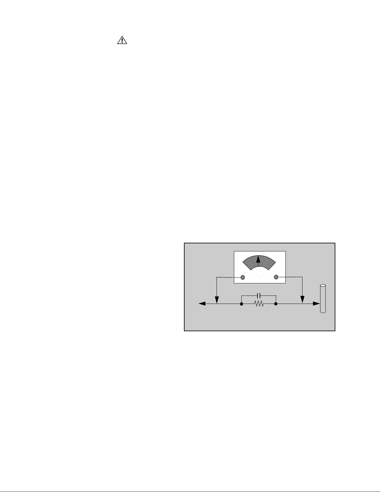
Leakage Current Hot Check (Fig. 1)
Plug the AC cord directly into the AC outlet. Do not use
an isolation transformer during the check.
Connect a 1.5kΩ 10 watt resistor in parallel with a
0.15µF capacitor between an exposed metallic part
and ground. Use earth ground, for example a
water pipe.
Using a DVM with a 1000 ohms/volt sensitivity or
higher, measure the AC potential across the resistor.
Repeat the procedure and measure the voltage
present with all other exposed metallic parts.
Verify that any potential does not exceed 0.75 volt
RMS. A leakage current tester (such a Simpson Model
229, Sencore Model PR57 or equivalent) may be used
in the above procedure, in which case any current
measure must not exceed 1/2 milliamp. If any
measurement is out of the specified limits, there is a
possibility of a shock hazard and the Receiver must be
repaired and rechecked before it is returned to the
customer.
AC VOLTMETER
COLD
WATER
PIPE
(GROUND)
0.15µF
TO INSTRUMENT’S
EXPOSED METAL
PART S
1500Ω,10 W
Figure 1. Hot Check Circuit
X-ray Radiation
WAR NING: The potential source of X-ray radiation in the
TV set is in the High Voltage section and the picture tube.
Note: It is important to use an accurate, calibrated
high voltage meter.
Set the brightness, picture, sharpness and color
controls to Minimum. Measure the High Voltage. The
high voltage should be 28.30kV ± 1.25kV. If the upper
limit is out of tolerance, immediate service and
correction is required to insure safe operation and to
prevent the possibility of premature component failure.
Horizontal Oscillator Disable Circuit Test
This test must be performed as a final check before the
Receiver is returned to the customer. See Horizontal
Oscillator Disable Circuit Procedure Check in
this manual.
- 2 -
Important Safety Notice . . . . . . . . . . . . . . . . . . 2
Safety Precautions . . . . . . . . . . . . . . . . . 2
Service Notes . . . . . . . . . . . . . . . . . . . . . . . . . . . 4
Horizontal Oscillator Disable Circuit . . . . 5
Receivers Feature Table . . . . . . . . . . . . . . . . . . 6
Location of Controls (Receiver)
Receiver Front Control Panel . . . . . . . . . 7
Location of Controls (Remote)
EUR511502 . . . . . . . . . . . . . . . . . . . . . . 8
Service Adjustments
(Electronic Control). . . . . . . . . . . . . . . . . . 24
Sub-Brightness . . . . . . . . . . . . . . . . . . . 24
Sub-Contrast. . . . . . . . . . . . . . . . . . . . . 24
Tint/Color Adjustment . . . . . . . . . . . . . . 24
Color Temperature Adjustment . . . . . . . 25
Complete Adjustment . . . . . . . . . . . . . . 25
Horizontal Centering . . . . . . . . . . . . . . . 26
MTS Circuit Adjustment . . . . . . . . . . . . 26
Input Level Adjustment . . . . . . . . . . . . . 26
Stereo Separation Adjustment . . . . . . . 26
Clock Adjustment . . . . . . . . . . . . . . . . . 27
Vertical Size . . . . . . . . . . . . . . . . . . . . . 27
Service Adjustments
(Mechanical Controls). . . . . . . . . . . . . . . . 27
VCO Field Adjustment L105 . . . . . . . . . 27
Focus (Part of T551). . . . . . . . . . . . . . . 27
Disassembly for Service . . . . . . . . . . . . . . . . . . 9
Disassembly for CRT Replacement . . . . . . . . . 9
Chassis Service Adjustment Procedures . . . 10
131.0V B+ Voltage Confirmation . . . . . 10
Source Voltage Chart . . . . . . . . . . . . . . 10
High Voltage Check . . . . . . . . . . . . . . . 10
Purity and Convergence Procedures . . . . . . .11
Serviceman Mode (Electronic Controls) . . . . 14
Entering Serviceman Mode . . . . . . . . . 14
Toggle between Modes. . . . . . . . . . . . . 14
Exiting the Serviceman Mode . . . . . . . . 14
Sub-Data Adjustment (B) . . . . . . . . . . . 15
Cut-Off Adjustment (C) . . . . . . . . . . . . . 15
Pin Cushion Adjustment (D) . . . . . . . . . 16
MTS Adjustment (M). . . . . . . . . . . . . . . 16
PIP Adjustment (P) . . . . . . . . . . . . . . . . 17
Options Adjustment (S) . . . . . . . . . . . . 18
Comb Filter Adjustment (X) . . . . . . . . . 19
To Check Purity . . . . . . . . . . . . . . . . . . 20
Helpful Hints . . . . . . . . . . . . . . . . . . . . . 20
Instructional Flow Chart
for Serviceman Mode . . . . . . . . . . . . . . . . 21
Audio Signal Path Block Diagram . . . . . . . . . 28
Video Signal Path Block Diagram . . . . . . . . . 29
Video-Chroma Signal Path Block Diagram . . 30
IC101 VCJ IN/OUT Pins and Functions . . . . . 31
IC001 MPU IN/OUT Pins and Functions. . . . . 32
Component Identification . . . . . . . . . . . . . . . . 33
Parts List . . . . . . . . . . . . . . . . . . . . . . . . . . . . . 36
Schematics and Voltages
A-Board (Left Portion) . . . . . . . . . .Sheet-1A
A-Board (Right Portion) . . . . . . . . . Sheet-2A
C-Board . . . . . . . . . . . . . . . . . . . . . .Sheet-1B
Waveforms. . . . . . . . . . . . . . . . . . . .Sheet-1B
Layouts
A & C-Boards. . . . . . . . . . . . . . . . . .Sheet-1B
- 3 -
Service Notes
Note: These components are affixed with glue. Be careful not to break or damage any foil under the
component or at the pins of the ICs when removing. Usually applying heat to the component for a
short time while twisting with tweezers will break the component loose.
Leadless Chip Component
(surface mount)
Chip components must be replaced with identical chips
due to critical foil track spacing. There are no holes in
the board to mount standard transistors or diodes.
Some chips capacitor or resistor board solder pads
may have holes through the board, however the hole
diameter limits standard resistor replacement to 1/8
watt. Standard capacitor may also be limited for the
same reason. It is recommended that identical
components be used.
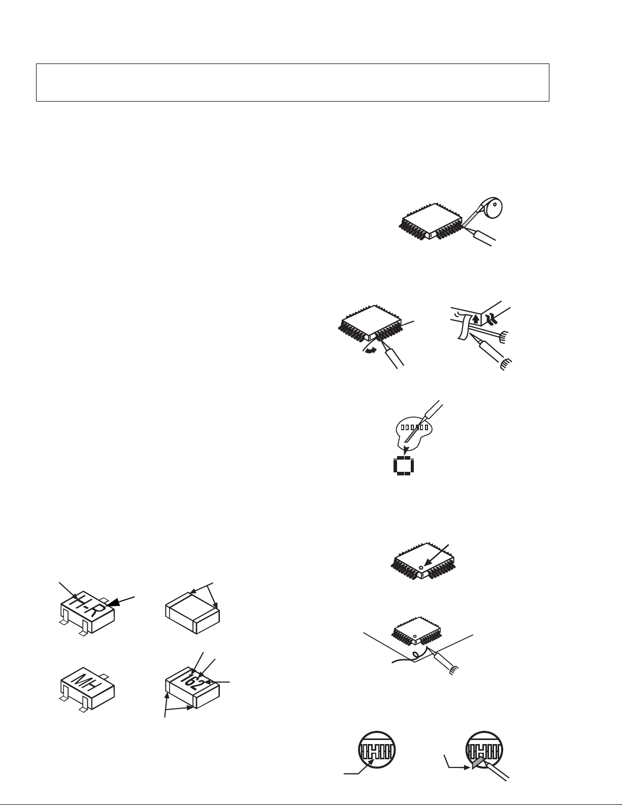
Chip resistor have a three digit numerical resistance
code - 1st and 2nd significant digits and a multiplier.
Example: 162 = 1600 or 1.6kΩ resistor, 0 = 0Ω (jumper).
Chip capacitors generally do not have the value
indicated on the capacitor. The color of the component
indicates the general range of the capacitance.
Chip transistors are identified by a two letter code. The
first letter indicates the type and the second letter, the
grade of transistor.
Chip diodes have a two letter identification code as per
the code chart and are a dual diode pack with either
common anode or common cathode. Check the parts
list for correct diode number.
Component Removal
1. Use solder wick to remove solder from component
end caps or terminal.
2. Without pulling up, carefully twist the component
with tweezers to break the adhesive.
3. Do not reuse removed leadless or chip
components since they are subject to stress
fracture during removal.
Chip Component Installation
1. Put a small amount of solder on the board
soldering pads.
2. Hold the chip component against the soldering
pads with tweezers or with a miniature alligator clip
and apply heat to the pad area with a 30 watt iron
until solder flows. Do not apply heat for more than
3 seconds.
TYPE
Chip Components
GRADE
c
SOLDER
CAPS
How to Replace Flat-IC
- Required Tools -
• Soldering iron • De-solder braids
• Iron wire or small awl • Magnifier
1. Remove the solder from all of the pins of a Flat-IC
by using a de-solder braid.
De-Solder
Flat-IC
2. Put the iron wire under the pins of the Flat-IC and
pull it in the direction indicated while heating the
pins using a soldering iron. A small awl can be
used instead of the iron wire.
Iron
Wire
Pull
Soldering
Iron
Soldering
Iron
3. Remove the solder from all the pads of the Flat-IC
by using a de-solder braid.
Soldering
Iron
De-Solder
Braid
Flat IC
4. Position the new Flat-IC in place (apply the pins of
the Flat-IC to the soldering pads where the pins
need to be soldered). Properly determine the
positions of the soldering pads and pins by
correctly aligning the polarity symbol.
Polarity Symbol
123.........
5. Solder all pins to the soldering pads using a fine
tipped soldering iron.
Braid
Awl
b
ANODES
MH DIODE
e
TRANSISTOR
COMMON
CATHODE
SOLDER
CAPS
CAPACITOR
1ST DIGIT
RESISTOR
2ND DIGIT
MULTIPLIER
=1600 = 1.6k
Solder
Soldering
Iron
6. Check with a magnifier for solder bridge between
the pins or for dry joint between pins and soldering
pads. To remove a solder bridge, use a de-solder
braid as shown in the figure below.
De-Solder
Braid
Solder
Bridge
Soldering
Iron
- 4 -

Service Notes (Continued)
IMPORTANT: To protect against possible damage to
the solid state devices due to arcing or static discharge,
make certain that all ground wires and CTR DAG wire
are securely connected.
CAUTION: The power supply circuit is above earth
ground and the chassis cannot be polarized. Use an
isolation transformer when servicing the Receiver to
avoid damage to the test equipment or to the chassis.
Connect the test equipment to the proper ground ( ) or
( ) when servicing, or incorrect voltages will be
measured.
WARNING: This Receiver has been designed to meet
or exceed applicable safety and X-ray radiation
protection as specified by government agencies and
independent testing laboratories.
To maintain original product safety design standards
relative to X-ray radiation and shock and fire hazard,
parts indicated with the symbol on the schematic
must be replaced with identical parts. Order parts from
the manufacturer’s parts center using the parts
numbers shown in this service manual, or provide the
chassis number and the part reference number.
For optimum performance and reliability, all other parts
should be replaced with components of
identical specification.
Procedure:
1. Tune in a station to verify that the horizontal is
in sync.
2. Obtain a Monoscope pattern or a signal generator
crosshatch pattern
3. Connect the voltmeter (-) lead to TPD2 and the (+)
lead to TPD1 (junction of D55b anode, R556 &
R557). Set Bright level to (0) and Picture for a 1.8
volt reading on the voltmeter.
4. Turn the Receiver OFF. Connect a jumper across
IC803 pin 3 and pin 4. Apply +9V DC to cathode of
D001.
5. Reduce the AC supply voltage to approximately
45V. Connect the high voltage meter to the CRT
anode. (H.V. button).
Note: Use the Dag Ground (C10 on the CRT Board)
to connect the (-) lead of the meter.
6. Turn the Receiver ON. Slowly increase the AC
supply voltage and verify that the high voltages
does not exceed 37.1kV when horizontal; just
begins to pull out of sync. If the high voltage is not
within the specified limit, the cause must be
determined and corrected before the Receiver is
returned to the customer.
Horizontal Oscillator Disable Circuit
This chassis employs a special circuit to protect
against excessive high voltage and beam current. If, for
any reason, the high voltage and beam current exceed
a predetermined level this protective circuit activates
and detunes the horizontal oscillator that limits the high
voltage. The over-voltage protection circuit is not
adjustable. However, if components indicated by the
symbol on the schematic in either the horizontal
sweep system or the over-voltage protection circuit
itself are changed, the operation of the circuit should be
checked using the following procedure:
Equipment needed to check the disabled circuit:
1. Voltmeter (0 - 200V scale)
2. High Voltage Meter (0- 50kV)
3. Variac or Isolation Transformer
- 5 -
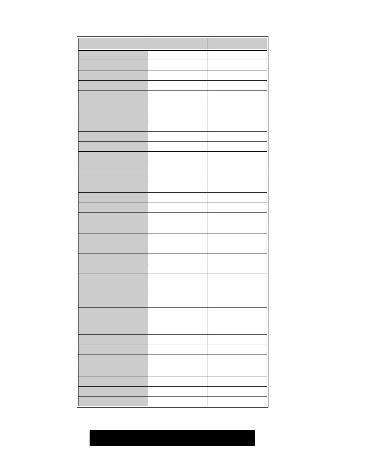
Receiver Feature Table
FEATURE\MODEL CT-27D10B/UB CT-27D10DB
Chassis NA8 NA8
Tunning system 96K 96K
# of channels 181 181
Menu language Eng/Span/Fr Eng/Span/Fr
Closed Caption XX
V-Chip XX
75 Ω input XX
Remote Model # EUR511502 EUR511502
Picture tube M68LGL061X M68LGL061X
Black Face Regular Tube XX
Comb Filter 3 Line Digital 3 Line Digital
H. Edge Correction XX
V/A norm XX
Color Temp XX
MTS/SAP/DBX XX
BASS/BL/TRE Control XX
AI Sound XX
Surround XX
Built-in audio power 5Wx2 (10%) 5Wx2 (10%)
# of speakers 22
A/V in (rear/front) 3(2/1) 3(2/1)
S-VHS Input (rear/front) 1/0 1/0
Component Input
(Y,Pb,Pr)
Audio Out
(FAO: F, VAO: V)
Headphone Jack Mini plug Mini plug
Dimensions mm
(WxDxH) in
Weight (kg/lbs) 35/77.2 35/77.2
Power source (V/Hz) 120/60 120/60
Anode voltage 28.30kV ± 1.25kV 28.30kV ± 1.25kV
Video input jack
Audio input jack 500mV RMS 47kΩ 500mV RMS 47kΩ
A-Board TNP2AH017 NIL NIL
665.2x544.5x594.8
1V
p-p
11
F, V F, V
665.2x544.5x594.8
26.2x21.5x23.5
75Ω, phono jack 1V
26.2x21.5x23.5
75Ω, phono jack
p-p
C-Board TNP2AA047 AP AP
Table 1. Receiver Features
Specifications are subject to change without notice or obligation.
Dimensions and weights are approximate.
- 6 -
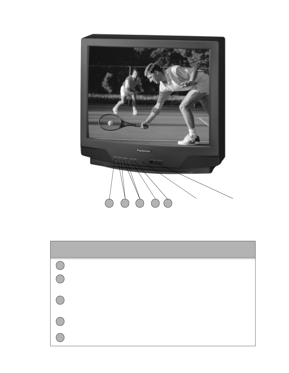
Location of Controls (Receiver)
1
4 532
Remote Control
Sensor
Front A/V Input
Figure 2. Location of Controls (Receiver).
Quick Reference Control Operation
Quick Reference
Control Operation
1
Power Button - Press to turn ON or OFF.
Volume Buttons - Press to adjust Sound Level, or to adjust Audio Menus, Video
2
Menus, and select operating features when menus are displayed
Channel Buttons - Press to select programmed channels. Press to highlight desired
features when menus are displayed. Also use to select Cable Converter box channels
3
after programming Remote Control Infra-red codes (the TV/AUX/CABLE switch must
be set in CABLE position).
Action Button - Press to display Main Menu and access On Screen feature and
4
Adjustment Menus.
5
TV/Video Button - Press to select TV or Video Input.
- 7 -
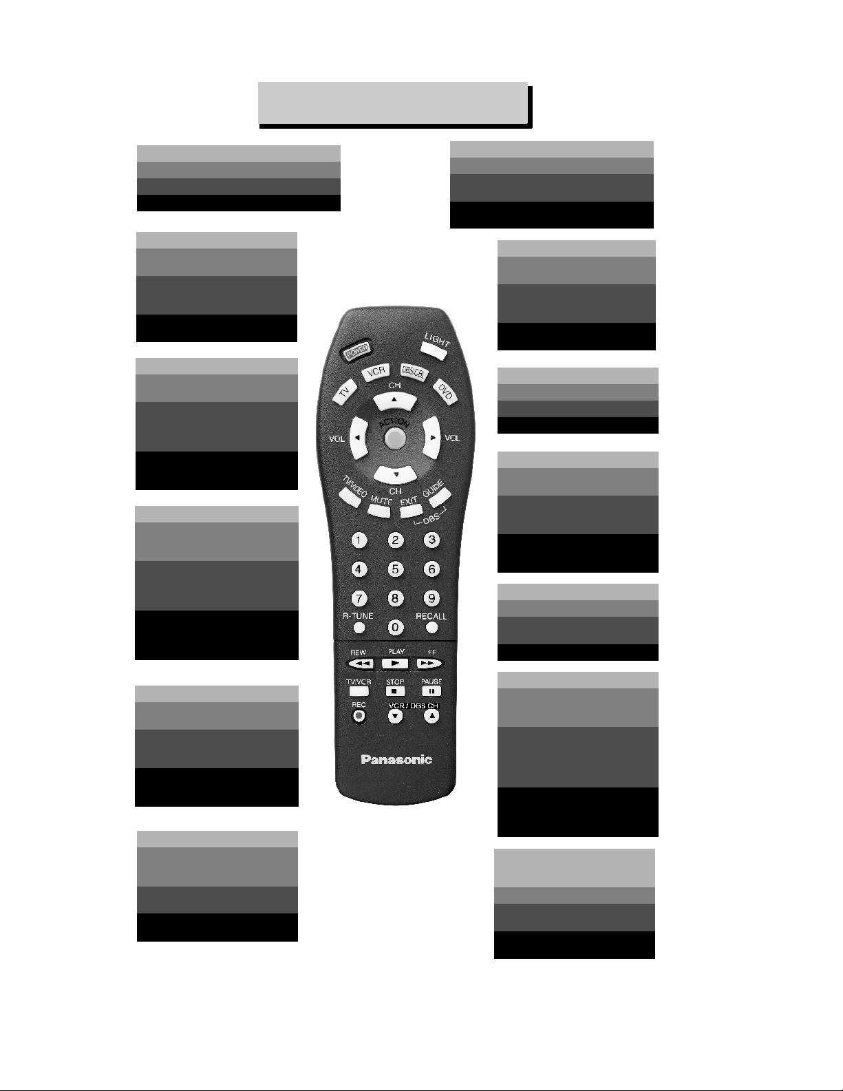
Location of Controls (Remote)
REMOTE CONTROL
POWER
Press to turn ON and OFF.
Presione para ENCENDER y APAGAR.
Appuyer pour établir ou couper le contact.
TV/VIDEO
Press to select TV or Video
Mode.
Presione para seleccionar la
Modalidad de Televisión ó
Video.
Appuyer pour sélectionner le
mode télé ou vidéo.
VOL
Press to adjust TV sound and
navigate in menus.
Presione para ajustar el
sonido de la Televisión y
accesar opciones en
los menús.
Appuyer pour régler le niveau
sonore et se déplacer au sein des
menus.
MUTE
Press to mute sound. Press
to access and cancel (CC)
Closed Caption.
Presione para silenciar el
sonido. También presione
para activar y cancelar la
Modalidad de Subtítulos (CC).
Appuyer pour couper le son.
Appuyer pour mettre le décodeur
de sous-titres (CC) en ou hors
circuit.
LIGHT
Press to light remote control buttons.
Presione para iluminar los botones del
control remoto.
Appuyer pour éclairer les touches de la
télécommande.
TV, VCR, DBS/CBL, DVD
Press to select remote
operation.
Presione para seleccionar el
funcionamiento del Control
Remoto.
Appuyer pour sélectionner le
fonctionnement télécommandé.
EXIT/GUIDE
DBS function buttons.
Botones de función DBS.
Touches de fonctions DBS.
CH
Press to select next channel
and navigate in menus.
Presione para seleccionar el
siguiente canal u opción en
el menú.
Appuyer pour sélectionner le
prochain canal et pour se déplacer
au sein des menus.
ACTION
Press to access menus.
Presione para accesar los
menús.
Appuyer pour accéder aux menus.
“0”~ “9”
Press numeric keypad to
select any channel.
Presione el teclado numérico
para seleccionar cualquier
canal.
Appuyer sur une touche
numérique du clavier pour
sélectionner un canal.
R-TUNE
Press to switch to previously
viewed channel or video
mode.
Presione para regresar al
canal previamente visto.
Appuyer pour revenir au canal
précédemment capté.
Figure 3. Location of Controls (Remote).
EUR511502
- 8 -
RECALL
Press to display time,
channel, sleep timer, and
other options.
Presione para visualizar la
Hora (Time), Canal (Channel),
Cronómetro de Apagado
Automático (Sleep Timer), y
otras opciones.
Appuyer pour afficher l'heure, le
numéro du canal, l'état de la
minuterie-sommeil et d'autres
options.
REW, PLAY, FF, TV/VCR,
STOP, PAUSE, REC,
VCR/DBS CHANNEL
Component function buttons.
Botones de función de los
componentes.
Touches de fonctions d'appareil
auxiliaire.

Disassembly for Service
Back Cover
Remove all the screws marked with an arrow( )
from the back of the Receiver.
Note: Screw configuration, type, and number of
screws vary depending on the model of the
Receiver serviced and the application; various
models are covered in this Manual. Use same
hardware when reassembling the receiver.
• 3 screws at the top edge of the Receiver.
• 1 screw at each lower corner of the Receiver.
• 1 screw by the AC cord assembly.
• 1 screw by the A/V jacks.
• 1 screw by the Fly-back assembly.
A-Board - Main Chassis
1. Slide the chassis completely out of the guide rails.
2. Stand the Receiver on its edge. The underside of
the board is completely accessible for component
replacement.
Note: Some tie-wraps that secure the wire dressings
may need to be unfastened for chassis
removal.
C-Board - CRT Output
Plugs into the socket on the CRT neck.
Speakers
Speaker is secured to the cabinet’s front with 4
screws.
Keyboard Push Button Assembly
Fastened to the inside of the cabinet front with up
to 3 screws.
Disassembly for CRT Replacement
1. Discharge the CRT as instructed in the Safety
Precautions (see page 2).
2. Disconnect the yoke (DY) plug, degaussing coil
(DEG) plug and the CRT 2nd anode button from
the main board.
3. Remove the C-Board from the CRT base and
unplug the black wire (CRT dag ground) C10.
4. Disconnect the A11, A12, and Speakers plugs from
the A-Board.
5. Lift the Main Chassis (A-Board) and all mounted
boards completely out with the CRT Board attached.
CRT Replacement
1. Perform Disassembly for CRT Replacement
procedure.
2. Insure that the CRT H.V. Anode button is
discharged before handling the CRT. Read the
Safety Precautions (see page 2) on handling the
picture tube.
3. Remove the components from the CRT neck and
place the cabinet face down on a soft pad.
4. Note the original order for the CRT mounting
hardware as they are remove from the CRT
mounting brackets at each corner of the CRT.
5. Remove the CRT with the degaussing coil and the
dag ground braid attached.
6. Note the original locations and mounting of the
degaussing coil and the dag ground assembly to
insure proper reinstallation on the replacement
CRT.
To remove and re-mount the degaussing coil:
The degaussing coil is held in place by clampers
fastened to the CRT corner ears. These clampers
must be installed onto the replacement CRT prior
to mounting the degaussing coil.
To remove and re-mount the dag ground braid:
a.Unhook the coil spring from the bottom corners
of the CRT ears.
b.Release the braid loop from the upper corners of
the CRT ears.
7. Mount the dag ground braid on the replacement
CRT. Position the degaussing coil with new ties.
Dress coil as was on the original CRT.
8. Replace the components on CRT neck and
reinstall into cabinet. Verify that all ground wires
and circuit board plugs get connected.
- 9 -
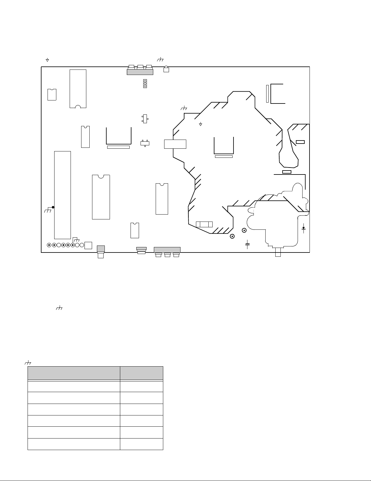
Chassis Service Adjustment Procedures
All service adjustments are factory preset and should not require adjustment unless controls and/or
associated components are replaced.
Note: Connect the (-) lead of the voltmeter to the appropriate ground. Use IC803’s heat sink when the HOT ground
symbol ( ) is used. Otherwise, use COLD ground ( ) — Tuner shield, IC451’s heat sink or FA2.
Figure 4. A-Board Main Components
IC451
HOT ( )
RL801
IC 803
F801
TPD8
TPD9
C552
IC 002
FA1
DATA
T
T
U
U
N
N
E
E
R
R
TP15
CLK
IC 001
IC 6501
FA2
TP
IC 101
IC 2302
IC 2361
IC 551
IC 552
IC 003
SP
COLD ( )
IC 3001
MOMENTARILY CONNECT A JUMPER FOR ENTERING SERVICE MODE (FA1 to FA2 )
131.0V B+ Voltage Confirmation
Adjust Picture Menu for normalized video adjustments.
1. Set the Bright and the Picture to Minimum by
using the Picture Menu.
2. Connect the DVM between C809(+ side) and cold
ground ( ).
3. Confirm that B+ voltage is 131.0V ± 2.5V. This
voltage supplies B+ to the Horizontal Output &
Flyback circuits.
Source Voltage Chart
120V AC line input. Set the Bright and the Picture to
High Voltage Check
1. Select an active TV channel and confirm that
horizontal is in sync.
2. Adjust Brightness and Picture using Picture Icon
menu so video just disappears.
3. Confirm B+ 131V is within limit.
4. Using a high voltage meter confirm that the High
Voltage is 28.30kV ± 1.25kV.
Minimum by using the Picture Menu. Use cold ground
( ) for the (-) lead of the DVM.
Q 501
Q 551
D554
FOCUS SCREEN
LOCATION VOLTAGE
TPD8 27.4V ± 2V
TPD9 13.0V ± 2V
C552 (+) side 8.0V ± 1V
IC551 Pin3 9.0V ± 0.5V
D554 Cathode 220V ± 15V
C572 (+) side 5.0V ± 0.25V
- 10 -
Purity and Convergence Procedure
Adjustment is necessary only if the CRT or the
deflection yoke is replaced or if the setting was
disturbed. The complete procedure consists of:
1. Vertical Raster Shift Adjustment. (Only for Models
with Purity/Convergence Assembly with 4 Pairs
of Rings).
2. Initial static convergence.
3. Setting the purity.
4. Final static convergence.
When the CRT or the Yoke is Replaced
Place the yoke on the CRT neck (do not tighten
the clamp).
For a 2-piece assembly (see Fig. 5):
Position purity/convergence assembly as shown and
tighten clamp snugly. Remove the hot-melt glue seal
on assembly and position like tabs of purity device
together at 12 o’clock to reduce its magnetic field
effect.
R&B Convergence Rings
R&B&G Convergence Rings
G3 G4
Purity Rings Centered
Over G3/G4 Gap
For a 1-piece assembly (see Fig. 8):
Position like tabs of purity devices together at 12
o’clock to reduce any magnetic field effect. (For better
results, note part number and look for specifications at
Service Center)
Figure 8. Positioning of Purity/Convergence
Assembly (1-piece assembly)
For either assemblies:
Turn the Receiver ON. Operate the Receiver for 60
minutes using the first Purity Check field (white screen)
to stabilize the CRT.
Fully degauss the Receiver by using an external
degaussing coil.
Slide the deflection yoke back and forth on the neck of
the CRT until it produces a near white, uniform raster.
Figure 5. Positioning of Purity/Convergence Assembly
(2-piece assembly)
For models using 4 pairs of rings, place the vertical
raster shift tabs at 3 o’clock (90
o
from the purity and
convergence tabs, see Fig. 6 and Fig. 7)
R&B Convergence Rings
R&B&G Convergence Rings
Vertical Raster Shift Ring
G3 G4
Purity Rings Centered
Over G3/G4 Gap
Figure 6. Positioning of Purity/Convergence Assembly
(4 Pairs of Rings)
R&B&G Convergence Rings
R&B Convergence Rings
Vertical Raster
Shift Rings
Purity Rings
90
o
Figure 7. Positioning of Purity/Convergence Assembly
(4 Pairs of Rings)
Vertical Raster Shift Adjustment (Only for
Models with Purity/Convergence Assembly with 4
Pairs of Rings).
Apply a green pattern with a horizontal line, adjust the
Deflection Yoke so that has no tilt, then secure it.
Adjust center line of the pattern with the mechanical
center of the CRT, this center is determined by two
marks at the side edges of the screen. To adjust the
line, once the vertical raster shift tabs are place at 3
o’clock to reduce its magnetic field effect (see Fig. 6
and Fig. 7) open the tabs the same angle from the
center, until the center line of the pattern becomes a
straight line, centered with the marks of the CRT. (see
Fig. 9)
Center line
from pattern
Mechanical
Center Marks
Vertical Raster Shift tabs
Figure 9. Ve r ti c al R as t e r S h if t Ad j u st m en t
(4 pairs of rings assembly)
Open the
same angle
from center
- 11 -
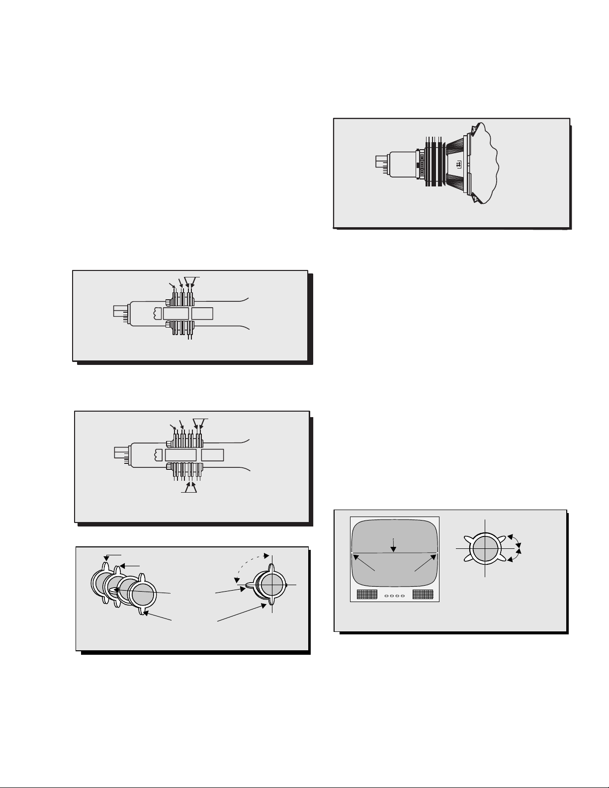
Initial Center Static Convergence
Connect a dot/cross hatch generator to the Receiver
and tune in a signal. Observe misconvergence at
center of the screen only.
Adjust the R&B pole magnets; by separating tabs and
rotating to converge blue with red.
Adjust the R&B and R&B&G pole magnets: by
separating tabs and rotating to converge blue and red
(magenta) with green.
Note: Precise convergence at this point is
not important.
Purity Adjustment
When the Receiver is in the Serviceman Mode for
making electronic adjustments, press the Recall button
on the Remote Control to enter Purity Check. (See the
Service Adjustments Electronic Controls
procedure).
Operate the Receiver for 60 minutes using the first
Purity Check field (white screen) to stabilize the CRT.
Fully degauss the Receiver by using an external
degaussing coil.
Press the Recall button on the Remote Control again
until the Purity Check (green screen) appears.
For a 2-piece assembly (see Fig. 5):
Loosen the deflection yoke clamp screw and move the
deflection yoke back as close to the purity magnet
as possible.
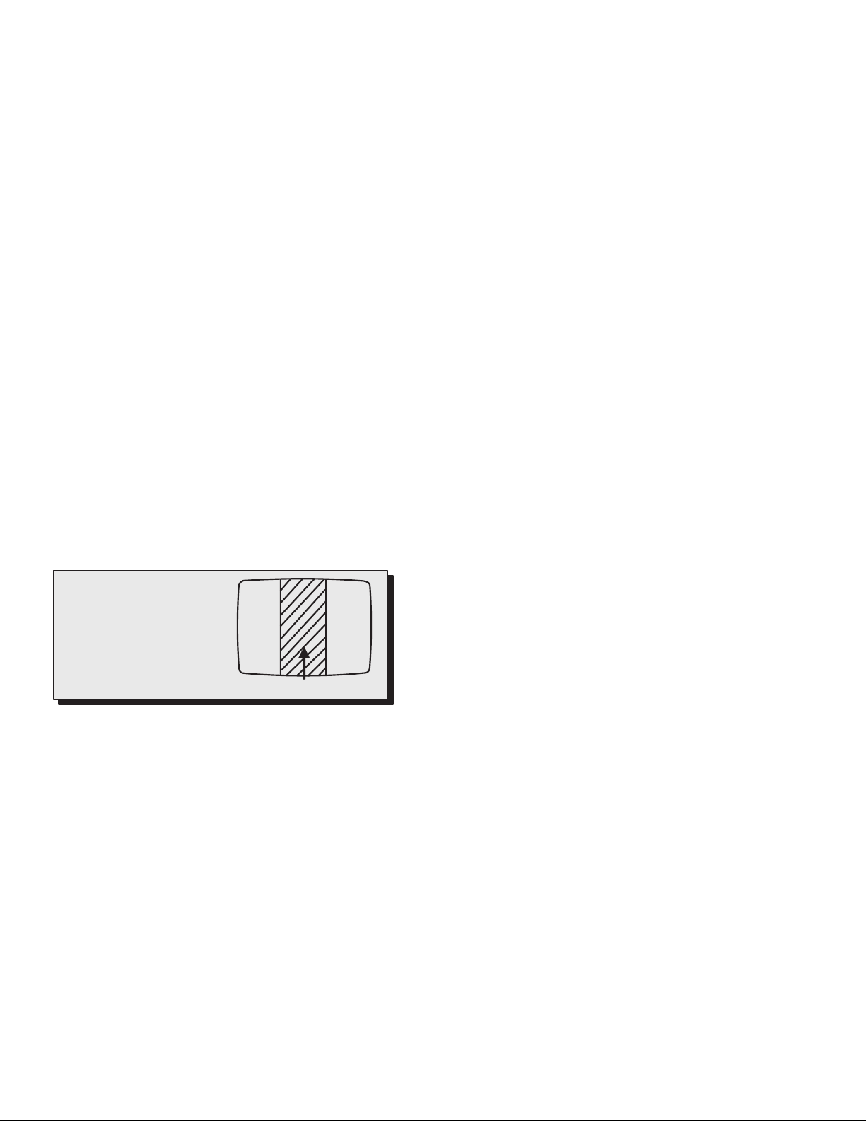
Adjust the Purity rings to set the vertical green raster
precisely at the center of the screen (see Fig. 10).
NOTES:
1. CRT warm up with white screen
(three guns activated) is needed
to stabilize the shadow mask
expansion.
2. Initial center static convergence
(roughly centers three gun
beams) is required in order to
perform purity adjustment.
Figure 10. Green Raster Adjustment
Slowly move the deflection yoke forward until the best
overall green screen is displayed.
For a 1-piece assembly (see Fig. 8):
Slowly move the deflection yoke and purity rings
assembly toward the CRT board and adjust the purity
magnet rings to set vertical green raster at center of
screen (see Fig. 10).
Gradually move the deflection yoke & purity rings
forward and adjust for best overall green screen.
Continue from here for either assemblies:
Tighten the deflection yoke clamp screw.
Press the Recall button on the Remote Control again
until the purity check (blue screen) and (red screen)
appear and observe that good purity is obtained on
each respective field.
Press the Recall button on the Remote Control again
until Purity check (white screen) appears. Observe the
screen for uniform white. If purity has not been
achieved, repeat the above procedure.
Green Raster
Final Convergence Procedure (see Fig. 11
through Fig. 13):
Note: Vertical size and focus adjustments must be
completed prior to performing the convergence
adjustment. Connect a dot pattern generator to the
Receiver. The Brightness level should not be higher
than necessary to obtain a clear pattern.
Converge the red and the blue dots at the center of the
screen by rotating the R&B pole Static Convergence
Magnets.
Align The converged red/blue dots with the green dots
at the center of the screen by rotating the R&B&G pole
Static Convergence Magnets. Melt wax with soldering
iron to reseal the magnets.
Slightly tilt vertically and horizontally (do not rotate) the
deflection yoke to obtain a good overall convergence.
If convergence is not reached at the edges, insert
permalloy (see following section) from the DY corners
to achieve proper convergence. Recheck for purity and
readjust if necessary.
After vertical adjustment of the yoke, insert wedge at 11
o’clock position, then make the horizontal
tilt adjustment.
Secure the deflection yoke by inserting two side
wedges at 3 and 7 o’clock positions.
Apply adhesive between tab (thin portion) of wedge
and CRT and place tape over the tab to secure to
the CRT.
Permalloy Convergence Corrector Strip
(Part No. 0FMK014ZZ)
This strip is used in some sets to match the yoke and
CRT for optimum convergence. If the yoke or CRT is
replaced, the strip may not be required.
First converge the set without the strip and observe
the corners.
If correction is needed:
1. Place strip between CRT and yoke, in quadrant
needing correction. Slowly move it around for
desired results.
2. Press adhesive tightly to the CRT and secure
with tape.
- 12 -
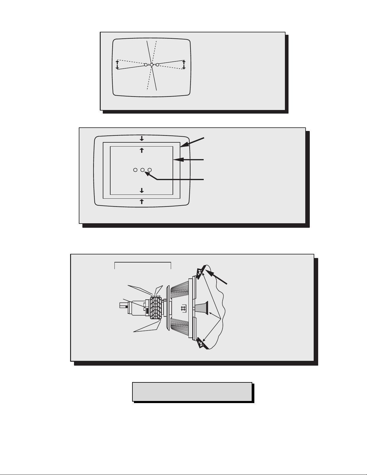
As the yoke is tilted
RGB
Figure 11. Vertical Yoke Movement
vertically, the rasters
produced by the
outside guns rotate in
opposite directions.
RGB
As the yoke is tilted horizontally, one
raster gets larger while the other gets
smaller
Figure 12. Horizontal Yoke Movement
Raster produced from one of the
outside electron beams
Raster from the other side electron
beam
Static convergence magnets are set for
center convergence
Static Convergence Magnets
Converges
R/B with G
Purity/Convergence
Assembly Clamp
Purity Rings Adj. on
Green Raster
11 o’clock Position
Converges
R with B
Double sided adhesive tape
3 o’clock Position
Yoke Positioning Wedges
for Dynamic Convergence
7 o’clock Position
Figure 13. Convergence Magnets and Wedges Location
Note: For models using 4 pairs of rings
assemblies see Fig. 6 for details
- 13 -
Serviceman Mode (Electronic Controls)
This Receiver has electronic technology using the I²C Bus Concept. It performs as a control function and it
replaces many mechanical controls. Instead of adjusting mechanical controls individually, many of the control
functions are now performed by using “On Screen Display Menu”. (The Serviceman Adjustment Mode.)
Note: It is suggested that the technician reads all the way through and understand the following procedure for
Entering/Exiting the Serviceman Adjustment Mode; then proceed with the instructions working with the
Receiver. When becoming familiar with the procedure, the Flow Chart for Serviceman Mode may be used
as a quick guide.
Quick Entry to Serviceman Mode:
At times when minor adjustments need to be done to the electronic controls, the method of Entering the
serviceman Mode without removal of the cabinet back is as follows using the Remote Control:
1. Select SET-UP icon and select CABLE mode.
2. Select TIMER icon and set SLEEP time for 30 Min.
3. Press ACTION button 3 times to exit menus.
4. Tune to the Channel 124.
5. Adjust VOLUME to minimum (0).
6. Press the VOL button (decrease) on Receiver. Red “CHK” appears in upper corner.
To toggle between Aging and Serviceman modes:
While the “CHK” is displayed on the left top corner of the CRT, pressing the Action and the Volume Up buttons
on the Receiver simultaneously will toggle between the modes. Red “CHK” for Serviceman and yellow “CHK” for
Aging.
7. Press the Power Button on the Remote Control to select one of seven Serviceman Adjustment Modes.
1) B= Serviceman VCJ SUB-DATA ADJUSTEMENT.
2) C= Serviceman VCJ CUT-OFF ADJUSTMENT.
3) D= Serviceman PIN CUSHION ADJUSTMENT.
4) M= Serviceman MTS ADJUSTMENTS.
5) P= Serviceman PIP ADJUSTMENT. (Models with PIP only)
6) S= Serviceman OPTIONS ADJUSTMENTS.
7) X = Serviceman COMB FILTER ADJUSTMENT.
8) “CHK” = Normal operation of CHANNEL and VOLUME .
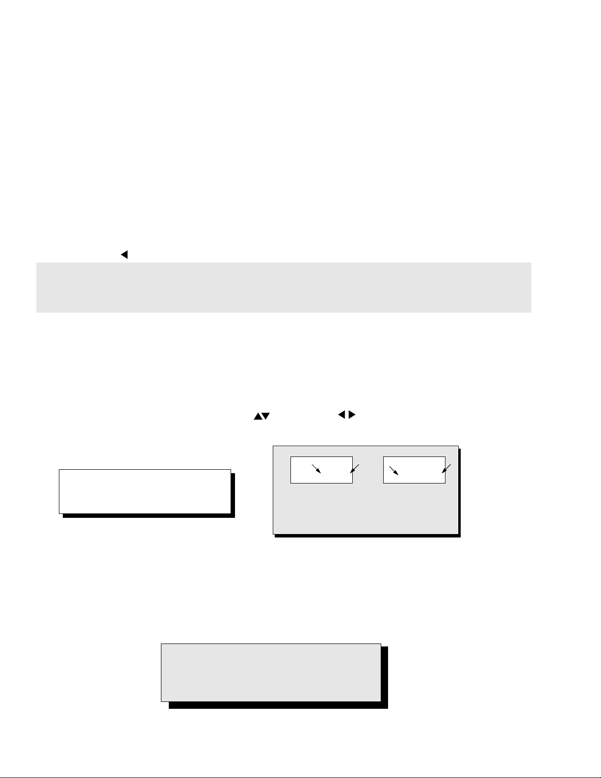
Note: Only the applicable settings for
the Receiver serviced will be
available (See a in Fig. 14).
b
32 B 0 2 215 C 0
An address Menu appears in the right
hand corner of the screen
Figure 14. Serviceman Mode Menu Adjustments.
a
b
a
Exiting the Serviceman Mode:
Press the Action and the Power buttons on the Receiver simultaneously for at least 2 seconds.
THE RECEIVER EXITS SERVICEMAN MODE.
The Receiver momentarily shuts off; then comes back on tuned to channel 3 with a preset level of sound.
Any programmed channels, channels caption data and some others user defined settings will be erased.
IMPORTANT NOTE:
Always Exit the Serviceman Mode
Following Adjustments.
- 14 -
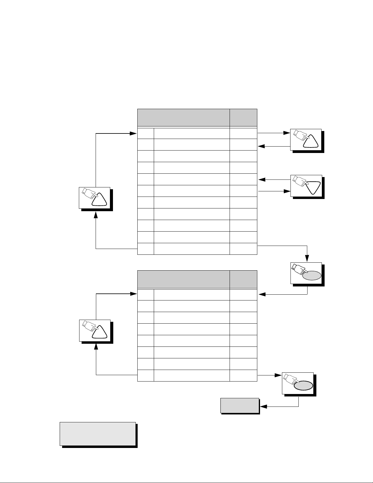
Press the Power Button on the Remote Control to select the Serviceman Adjustment .
For Adjustments:
1.Press Channel Up/Down on the
Remote Control to select one of
the available Service Adjustments
(a in Fig. 14).
Note: Write Down the original
value set (b in Fig. 14) for
each address before
modifying anything. It is
easy to erroneously adjust
the wrong item.
2.Press Volume Up/Down on the
Remote Control to adjust the
level of the selected Service
Adjustment (b in Fig. 14).
CH
Sub-Data Adjustment
B0 SUB-COLOR 31
B1 SUB-TINT 31
B2 SUB-BRIGHTNESS 31
B3 SUB-CONTRAST 16
B4 SUB-TINT VIDEO 16
B5 SUB-COLOR VIDEO 16
B6 SUB-TINT COMP 63
B7 SUB-COLOR COMP 31
B8 SUB SHARP TV/VIDEO 10
B9 SUB SHARP S-VHS/COMP 31
BA SUB-CONTRAST FIXED 15
Cut-Off Adjustment
Default
Level
Default
Level
CH
CH
PW
CH
IMPORTANT NOTE:
Always Exit the Serviceman
Mode Following Adjustments.
C0 CUT-OFF R 128
C1 CUT-OFF G 128
C2 CUT-OFF B 128
C3 USER BRIGHTNESS 31
C4 G DRIVE 64
C5 B DRIVE 64
C6 DRIVE C TEMP 8
C7 CONTRAST C TEMP 5
PW
To D Items.
- 15 -
 Loading...