

Panasonic CT-20G11 Owner’s Manual
rll IF1 IIIIIIIIPll
IIII I
Color Television
Operating Instructions
®
Read these instructions completely before operating this set.
Contents subject to change without notice or obligation.
Copyright 1996 by Matsushita Electric Corporation of America.
All dghts reserved. Unauthorized copying and distribution is aviolation of law.
ooooo oo CZ_)
CT-20G11
CT-2011S
Printed in Mexico
TQB2AA0010-1
Safety Instructions
WARNING
WARNING: To reduce the risk of electric shock do not remove cover' or back. No
user-serviceable parts inside. Refer servicing to qualified service personnel.
The lightningflash with ar- The exclamation pointwithin
row-head within a triangle A_. a triangle is intended to tell
are arisk ofelectricshockto tions are in the papers with
is intended to tell the user the userthatimportant oper-
that parts insidethe product _ ating and servi,.'inginstruc-
persons, the appliance.
Note To CATV System Installer: This reminder is provided to call the CATV system installer's attention to Article
820-40 of the NEC that provides guidelines for proper grounding and, in particular, specilie,s that the cable ground shall be
connected to the grounding system of the building, as close to the point of cable entry as practical.
Safety Instructions For Television Receivers
1. Read and apply the operating instructions provided with your television receiver.
2. Read all of the instructions given here and retain them for later use.
3. Unplug this television receiver from the wall outlet before cleaning. Do not use liquid or aerosol cleaners. Use a damp
cloth for cleaning.
4. Do not use attachments not recommended by the television receiver manufacturer as they may cause hazards.
5. Do not use this television receiver near water. For example: Avoid placing it near a bathtub, washbowl, kitchen sink, or
laundry tub, in a wet basement, or near a swimming pool, etc.
6. Do not place this television receiver on an unstable cart, stand, or table. The television receiver may fall, causing serious
injury to a child or adult, and serious damage to the appliance. Use only with a cart or stand recommended by the
manufacturer, or sold with the television receiver. Wall or shelf mounting should follow the manufacturer's instructions,
and should use a mounting kit approved by the manufacturer.
6A. An appliance and cart combination should be moved with care. Quick: stops, excessive force, and
uneven surfaces may cause the appliance and cart combination to overtum.
7. Slots and openings in the cabinet and the back or bottom are provided for ventilation, and to insure
reliable operation of the television receiver and to protect it from overheating. These openings must not be blocked or
covered. The openings should never be blocked by placing the television receiver on a bed, sofa, rug or other similar
surface. This television receiver should never be placed near or over a radiator or heat register. This television receiver
should not be placed in a built-in installation such as a bookcase unless proper ventilation is provided.
8. Operate only from the type of power source indicated on the marking label. If you ar,_=not sure of the type of power
supplied to your home consult your television dealer or local power company. For television receivers designed to
operate from battery power, refer to the operating instructions.
9. This television receiver is equipped with a polarized alternating-current line plug (a plug having one blade wider than the
other). 'This plug will fit into the power outlet only one way. This is a safety feature. If you are unable to insert the plug
fully into the outlet, try reversing the plug. If
the plug should still fail to fit, contact your
electrician to replace your obsolete outlet. Do
not defeat the safety purpose of the polarized
plug.
10.
Do not allow anything to rest on the power
cord. Do not locate this television receiver
where the cord will be abused by persons
walking on it.
11.
Follow all warnings and instructions marked
on the television receiver.
12.
Do not overload wall outlets and extension
cords as this can result in fire or electric
shock.
13.
Never push objects of any kind into this
television receiver through cabinet slots as
they may touch dangerous voltage points or
short out parts that could result in a fire or
electric shock. Never spill liquid ofany kind on
the television receiver.
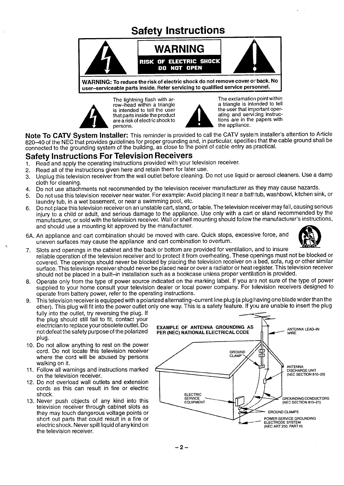
14.If an outside antenna is connected to the television equipment, be sure the antenna system is grounded so as to provide
some protection against voltage surges and built up static charges. In the U.S. Section 810 of the National Electrical
Code and in Canada Part 1 of the Canadian Electrical Code provides information with respect to proper grounding of the
mast and supporting structure, grounding of the lead-in wire to an antenna discharge unit, .,_izeof groundiing conductors,
location of antenna-discharge unit, connection to grounding electrodes, and requirement.'; for the grounding electrode.
See Figure.
15. For added protection for this te ev sion receiver during a lightning storm, or when it is left unattended and unused for long
periods of time, unplug itfrom the wall outlet and discohnect the antenna. This will prevent damage to the rece ver due to
lightning and power-line surges.
16. An outside antenna system should not be located in the vicinity of overhead power lines cr other electric light or power
circuits, or where it can fall into such power lines or circuits. When installing an outside, antenna system extreme care
should be taken to keep from touching such power lines or circuits as contact with them might be fatal.
17. Unplug this television receiver from the wall outlet, and refer servicing to qualified service personnel under the following
conditions:
a. When the power cord or plug is damaged or frayed.
b. If liquid has been spilled into the television receiver.
c. If the television receiver has been exposed to rain or water.
d. If the television receiver does not operate normally by following the operating instructions. Adjust only those controls
that are covered by the operating instructions as improper adjustment of other controls may result in damage and will
often require extensive work by a qualified technician to restore the television receiver to normal operation.
e. If the television receiver has been dropped or the cabinet has been damaged.
f. When the television receiver exhibits a distinct change in performance - this indicates a need for service.
113.Do not attempt to service this television receiver yourself as opening or removing cover.'; may expose you to dangerous
voltage or other hazards. Refer all servicing to qualified service personnel.
19. When replacement parts are required, be sure the service technician has used replacement parts specified by the
manufacturer that have the same characteristics as the original part. Unauthorized sul_stitutions may result in fire,
electric shock, or other hazards.
20. Upon completion of any service or repairs to this television receiver, ask the service technician to perform routine safety
checks to determine that the television is in safe operating condition.
21. WARNING: To prevent fire or shock hazard, do not expose this appliance to rain or moisture.
22. CAUTION: TO PREVENT ELECTRIC SHOCK DO NOT USE THIS (POLARIZED) PLUG WITH A RECEPTACLE OR
OTHER OUTLET UNLESS THE BLADES CAN BE FULLY INSERTED 1-O PREVENT BLADE EXPOSURE.
NOTE: This equipment is designed to operate inthe U.S.A., Canada and other countries wher_ the broadcasting system and
AC house current is exactly the same as in the U.S.A. and Canada.
Important Information Regarding Use of Video Games, Computers, Teletext or Other Fixed Image Displays.
The extended use of fixed image program material can cause a permanent "shadow irna!_e" on the picture tube. This
background image is viewable on normal programs in the form of a stationary fixed image. T_is type of irreversible picture
tube deterioration can be limited by observing the following steps:
A. Reduce the brightness/contrast setting to a minimum viewing level.
B. Do not display the fixed image for extended periods of time.
C. Turn the power off when not in actual use.
NOTE: The marking or retained image on the picture tube resulting from fixed image use is rot an operating defect and as
such is not covered by Warranty. This product is not designed to display fixed image patterns for extended periods of
time.
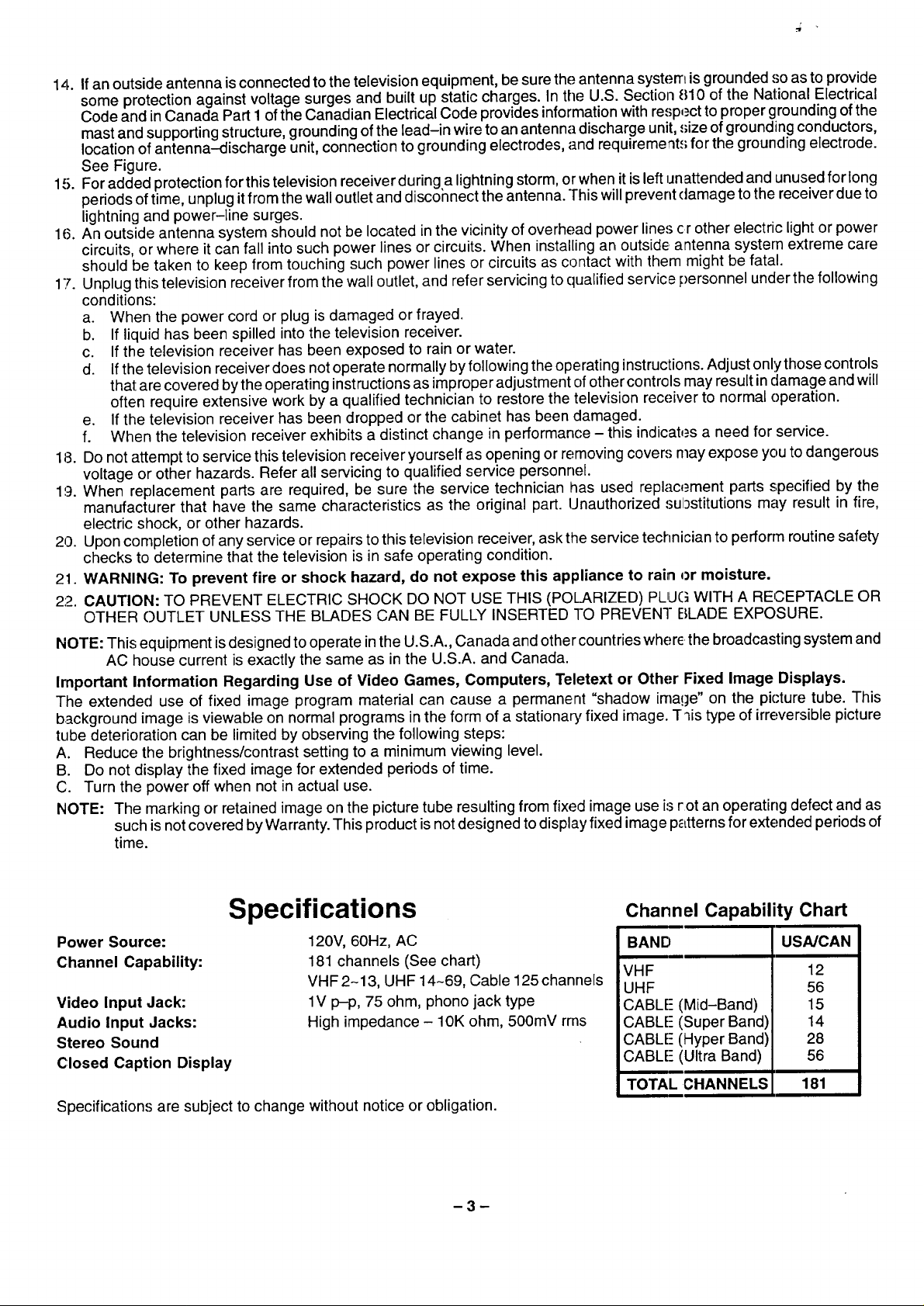
Specifications
Power Source:
C:hannel Capability:
Video Input Jack:
Audio Input Jacks:
Stereo Sound
Closed Caption Display
Specifications are subject to change without notice or obligation.
120V, 60Hz, AC
181 channels (See chart)
VHF 2-13, UHF 14~69, Cable 125 channels
1V p-p, 75 ohm, phono jack type
High impedance - 10K ohm, 500mV rms
-3-
Channel Capability Chart
BAND USNCAN
VHF
UHF
CABLE- (Mid-Band)
CABLE- (Super Band)
CABLE" (Hyper Band)
CABLE- (Ultra Band)
TOTALCHANNELS
12
56
15
14
28
56
181
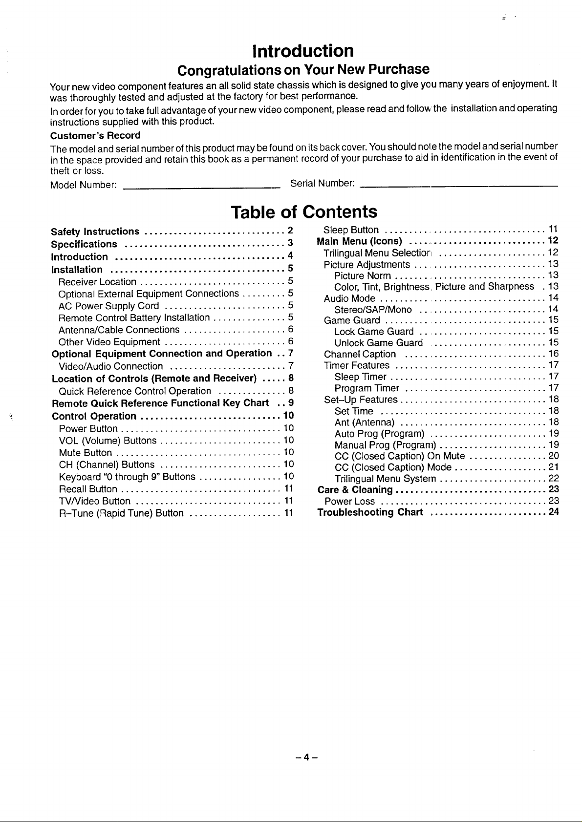
Introduction
Congratulations on Your New Purchase
Your new video component features an all solid state chassis which is designed to give you many years, of enjoyment. It
was thoroughly tested and adjusted at the factory for best performance.
In order for you to take full advantage of your new video component, please read and follow the installation and operating
instructions supplied with this product.
Customer's Record
The model and serial number of this product may be found on its back cover. You should note the model and serial number
in the space provided and retain this book as a permanent record of your purchase to aid in identification in the event of
theft or loss.
Model Number: Serial Number:
Table of Contents
Safety Instructions ............................. 2
Specifications ................................. 3
Introduction ................................... 4
Installation .................................... 5
Receiver Location .............................. 5
Optional External Equipment Connections ......... 5
AC Power Supply Cord ......................... 5
Remote Control Battery Installation ............... 5
Antenna/Cable Connections ..................... 6
Other Video Equipment ......................... 6
Optional Equipment Connection and Operation .. 7
Video/Audio Connection ........................ 7
Location of Controls (Remote and Receiver) ..... 8
Quick Reference Control Operation .............. 8
Remote Quick Reference Functional Key Chart .. 9
Control Operation ............................. 10
Power Button ................................. 10
VOL (Volume) Buttons ......................... 10
Mute Button .................................. 10
CH (Channel) Buttons ......................... 10
Keyboard "0 through 9" Buttons ................. 10
Recall Button ................................. 11
TV/Video Button .............................. 11
R-Tune (Rapid Tune) Button ................... 11
Sleep Button ................................. 11
Main Menu (Icons) .............................. 12
Trilingual Menu Selection ...................... 12
Picture Adjustments ........................... 13
Picture Norm ................................. 13
Color, "lint, Brightness, Picture and Sharpness . 13
Audio Mode ................................... 14
Stereo/SAP/Mono ............................ 14
Game Guard .................................. 15
Lock Game Guard ........................... 15
Unlock Game Guard ........................ 15
Channel Caption .............................. 16
Timer Features ................................ 17
Sleep Timer ................................. 17
Program Timer ............................. 17
Set-Up Features .............................. 18
Set Time .................................. 18
Ant (Antenna) .............................. 18
Auto Prog (Program) ........................ 19
Manual Prog (Program) ...................... 19
CC (Closed Caption) On Mute ................ 20
CC (Closed Caption) Mode ................... 21
Trilingual Menu System ...................... 22
Care & Cleaning ............................... 23
Power Loss .................................. 23
Troubleshooting Chart ........................ 24
-4-
Installation
Receiver Location
This unit is intended to be used with an optional stand or entertainment center. Consult your dealer for available options.
Locate for comfortable viewing. Avoid placing where sunlight or other bright light (including reflections) will fall on the
screen.
Use of some types of fluorescent lighting may reduce remote control transmitter range.
Adequate ventilation is essential to prevent internal component failure. Keep away from _reas of excessive heat or
moisture.
To insure optimum color purity do not position magnetic equipment (motors, fans, other speakers, etc.) nearby.
Optional External Equipment Connections
The Video/Audio connections between components can be made with shielded video and audio cables. For best perfor-
mance, video cables should utilize 75 ohm coaxial shielded wire. Cables are available from your dealer or electronic
supply house.
Before you purchase any cables, be sure you know what type of output and input connectors your various components
require. Also determine the length of cable you'll need.
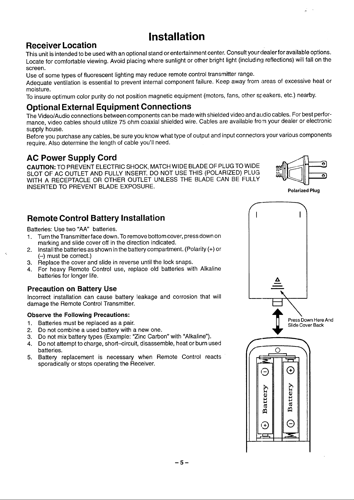
AC Power Supply Cord
CAUTION: TO PREVENT ELECTRIC SHOCK, MATCH WIDE BLADE OF PLUG TO WIDE
SLOT OF AC OUTLET AND FULLY INSERT. DO NOT USE THIS (POLARIZED) PLUG
WITH A RECEPTACLE OR OTHER OUTLET UNLESS THE BLADE CAN BE FULLY
INSERTED TO PREVENT BLADE EXPOSURE.
Polarized Plug
Remote Control Battery Installation
Batteries: Use two "AA" batteries.
1. Turn the Transmitter face down. To remove bottom cover, press down on
marking and slide cover off in the direction indicated.
2. Install the batteries as shown in the battery compartment. (Polarity (+)or
(-) must be correct.)
3. Replace the cover and slide in reverse until the lock snaps.
4. For heavy Remote Control use, replace old batteries with Alkaline
batteries for longer life.
Precaution on Battery Use
Incorrect installation can cause battery leakage and corrosion that will
damage the Remote Control Transmitter.
Observe the Following Precautions:
1. Batteries must be replaced as a pair.
2. Do not combine a used battery with a new one.
3. Do not mix battery types (Example: "Zinc Carbon" with "Alkaline").
4. Do not attempt to charge, short-circuit, disassemble, heat or burn used
batteries.
5. Battery replacement is necessary when Remote Control reacts
sporadically or stops operating the Receiver.
I I
A
m
m
Slide Cover Back
PressDownHereAnd
-5-
_Y=/
Installation (cont.)
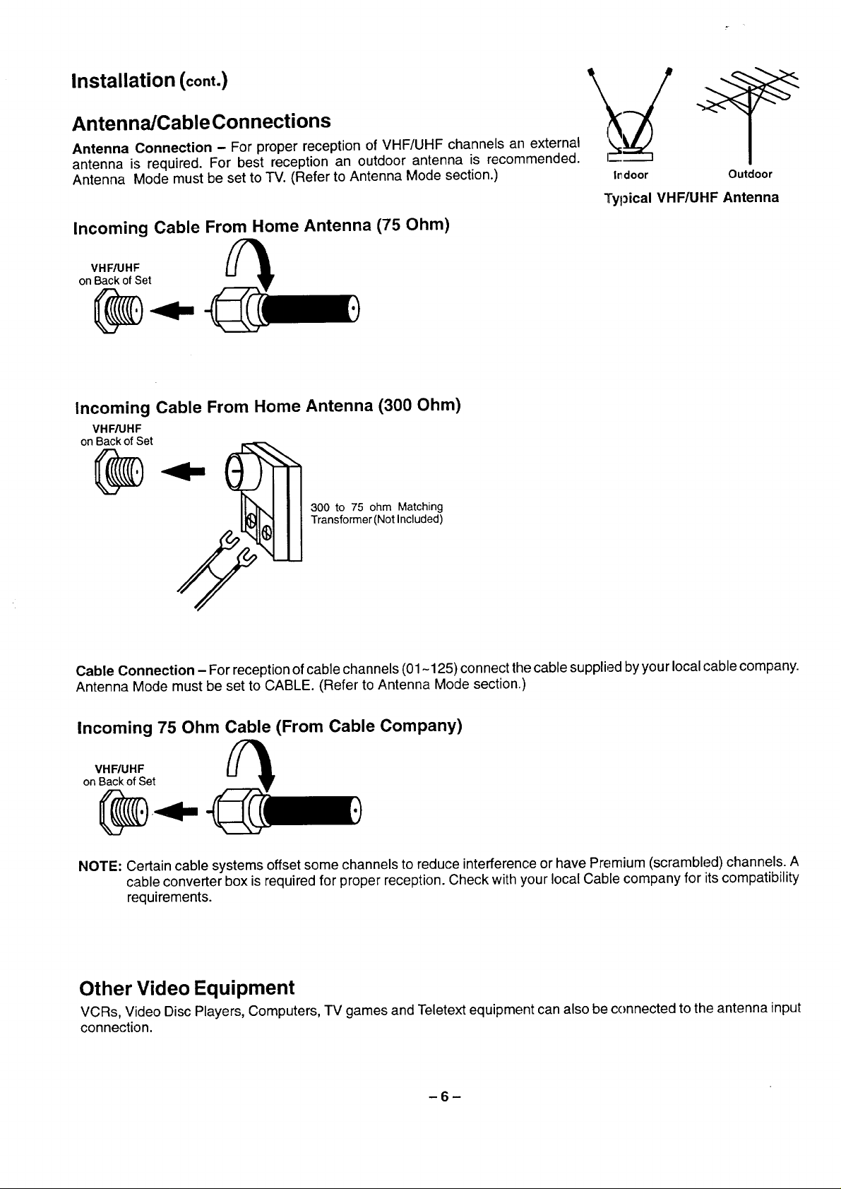
Anten na/Cable Connecti ons
Antenna Connection - For proper reception of VHF/UHF channels an external
antenna is required. For best reception an outdoor antenna is recommended.
Antenna Mode must be set to TV. (Refer to Antenna Mode section.)
Incoming Cable From Home Antenna (75 Ohm)
VHF/UHF
on Back of Set
Incoming Cable From Home Antenna (300 Ohm)
VHF/UHF
on Back of Set
I_door Outdoor
Typical VHF/UHF Antenna
300 to 75 ohm Matching
Transformer(Not Included)
Cable Connection - For reception ofcable channels (01-125) connect the cable supplied by your local cable company.
Antenna Mode must be set to CABLE. (Refer to Antenna Mode section.)
Incoming 75 Ohm Cable (From Cable Company)
VHF/UHF
onBackofSet
NOTE: Certain cable systems offset some channels to reduce interference or have Premium (scrambled) channels. A
cable converter box is required for proper reception. Check with your local Cable company for iitscompatibility
requirements.
Other Video Equipment
VCRs, Video Disc Players, Computers, TV games and Teletext equipment can also be connected to the antenna input
connection.
-6-
Optional Equipment Connection and Operation
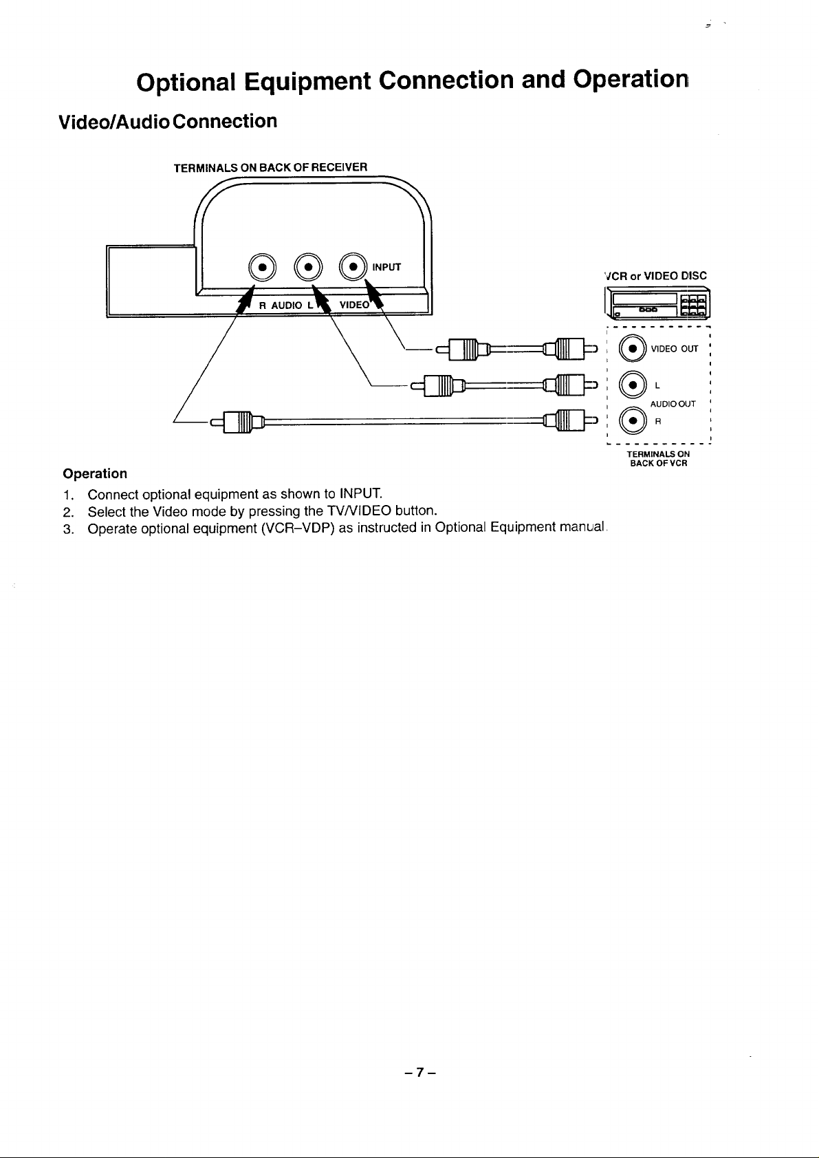
Video/Audio Connection
TERMINALS ON BACK OF RECEIVER
®®
R AUDIO L
Operation
1. Connect optional equipment as shown to INPUT.
2. Select the Video mode by pressing the TV/VIDEO button.
3. Operate optional equipment (VCR-VDP) as instructed in Optional Equipment manual
VCR or VIDEO DISC
VIDEO OUT
®.
AUDIO OUT
TERMINALS ON
BACK OF VCR
-7-
0oooo oo CZD
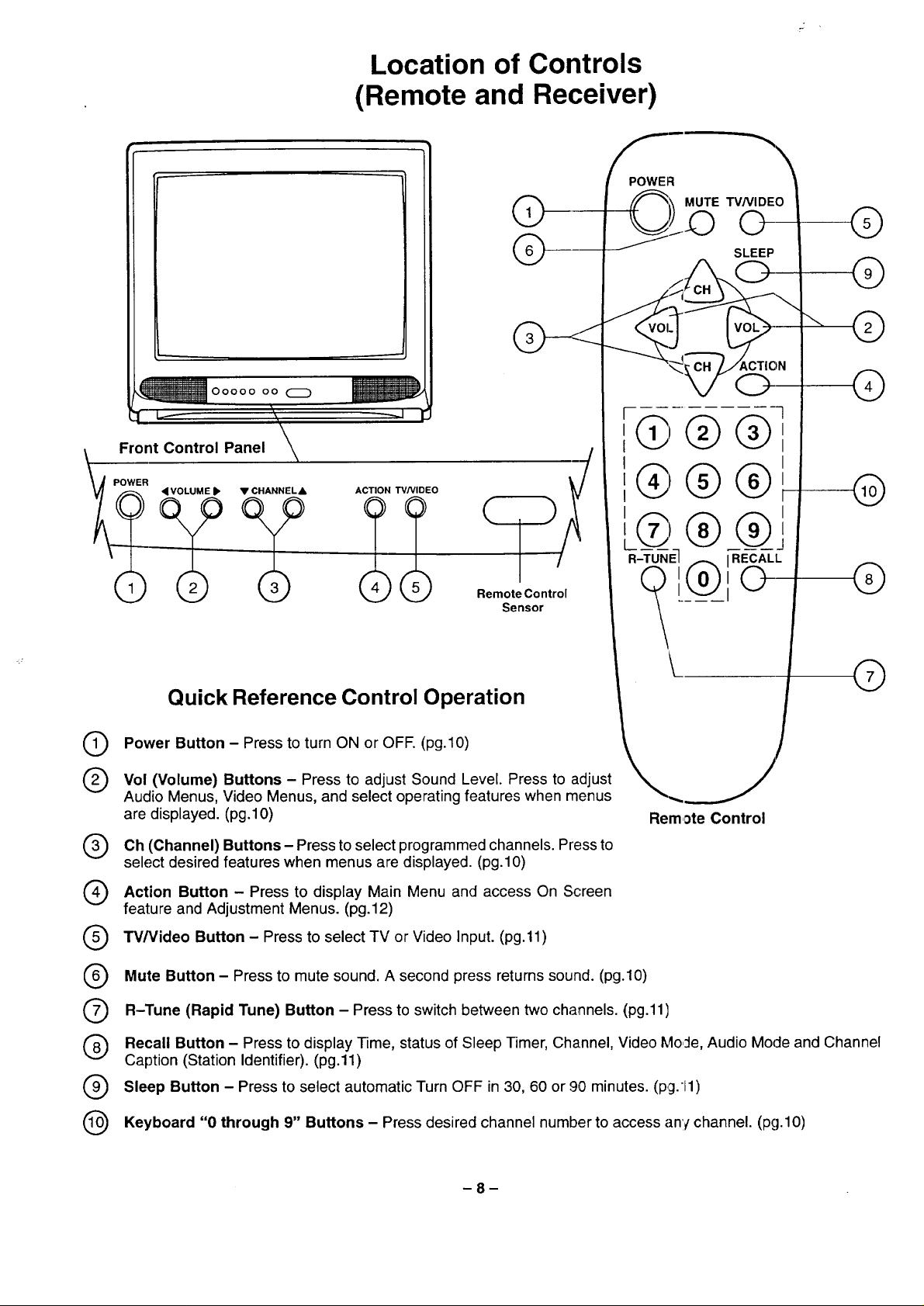
Location of Controls
(Remote and Receiver)
@
@@
_ pFr_t Control Panel
_ _ RemoteControl
Sensor
Quick Reference Control Operation
Power Button - Press to turn ON or OFF. (pg.10)
®
Vol (Volume) Buttons - Press to adjust Sound Level. Press to adjust
®
Audio Menus, Video Menus, and select operating features when menus
are displayed. (pg.10)
(Channel) programmed
Oh Buttons Press to select channels. Pressto
select desired features when menus are displayed. (pg.10)
Action Button - Press to Main Menu and access On Screen
feature and Adjustment Menus. (pg.12)
display
-!
@
@
RECALL
©
Rem,_te Control
"rv/Video Button - Press to select TV or Video Input. (pg.11)
@
Mute Button - Press to mute sound. A second press returns sound. (pg.10)
@
R-Tune (Rapid Tune) Button - Press to switch between two channels. (pg.11)
®
Recall Button - Press to display Time, status of Sleep Timer, Channel, Video Mode, Audio Mode and Channel
@
Caption (Station Identifier). (pg.11)
Sleep Button - Press to select automatic Turn OFF in 30, 60 or 90 minutes. (pg.ll)
@
Keyboard "0 through 9" Buttons - Press desired channel number to access any channel. (pg.10)
@
8
 Loading...