

Panasonic CT-13R17B, CT-13R27W, CT-13R37S Diagram
ORDER NO. MTNC020409C1
B1
Service Manual
Color Television
Main Manual
Panasonic
Models
CT-13R17B
CT-13R27W
CT-13R37S
This service manual is issued as a service guide for the models listed above.
Included in this manual are a set of schematic, block diagrams, functional descriptions, alignment procedures,
disassembly procedures and a complete parts list.
Chassis
TMB535
TMB535
TMB535
“WARNING! This Service Manual is designed for experienced repair technicians only and is not designed for use by the general public.
It does not contain warnings or cautions to advise non-technical individuals of potential dangers in attempting to service a product.
Products powered by electricity should be serviced or repaired only by experienced professional technicians. Any attempt to
service or repair the product or products dealt with in this Service Manual by anyone else could result in serious injury or death.”
The service technician is required to read and follow the “Safety Precautions” and “Important Safety Notice” in this Main Manual.
Copyright 2002 by Matsushita Electric Corporation of
America. All rights reserved. Unauthorized copying
and distribution is a violation of law.

CONTENTS
CONTENTS .................................................................................................................................................
Important Safety Notice ............................................................................................................................
Service Notes .............................................................................................................................................
GENERAL SPECIFICATIONS....................................................................................................................
DISASSEMBLY INSTRUCTIONS
1. REMOVAL OF ANODE CAP ............................................................................................................
2. NOTE FOR THE REMOVAL OF THE MAIN PCB............................................................................
SERVICE MODE LIST ................................................................................................................................
CONFIRMATION OF HOURS USED .........................................................................................................
WHEN REPLACING EEPROM (MEMORY) IC ..........................................................................................
ELECTRICAL ADJUSTMENTS
1. BEFORE MAKING ELECTRICAL ADJUSTMENTS .........................................................................
2. BASIC ADJUSTMENTS ....................................................................................................................
3. PURITY AND CONVERGENCE ADJUSTMENTS ...........................................................................
4. ELECTRICAL ADJUSTMENT PARTS LOCATION GUIDE (WIRING CONNECTION)...................
BLOCK DIAGRAM......................................................................................................................................
PRINTED CIRCUIT BOARDS
MAIN/CRT ..............................................................................................................................................
SCHEMATIC DIAGRAMS
MICON/TUNER ......................................................................................................................................
CHROMA................................................................................................................................................
TV POWER.............................................................................................................................................
DEFLECTION/CRT ................................................................................................................................
SOUND/AV .............................................................................................................................................
VOLTAGE LIST ..........................................................................................................................................
WAVEFORMS .............................................................................................................................................
MECHANICAL EXPLODED VIEW .............................................................................................................
MECHANICAL REPLACEMENT PARTS LIST .........................................................................................
ELECTRICAL REPLACEMENT PARTS LIST...........................................................................................
A1-1
A2-1
A2-2, A2-3
A3-1~A3-3
B-1
B-1
C-1
C-1
C-1
D-1
D-1, D-2
D-3
D-4
E-1, E-2
F-1~F-4
G-1, G-2
G-3, G-4
G-5, G-6
G-7, G-8
G-9, G-10
H-1
I-1, I-2
J-1
K1-1
K2-1~K2-3
A1-1
Important Safety Notice
Special components are used in this television set which are important for safety. These parts are identified on the
schematic diagram by the symbol and printed in BOLD TYPE on the replacement part list. It is essential that
these critical parts are replaced with the manufacturer's specified replacement part to prevent X-ray radiation, shock,
fire or other hazards. Do not modify the original design without the manufacturer's permission.
Safety Precautions
General Guidelines
An Isolation Transformer should always be used
during the servicing of a receiver whose chassis is not
isolated from AC power line. Use a transformer of
adequate power rating as this protects the technician
from accidents resulting in personal injury from electrical
shocks. It will also protect the Receiver from being
damaged by accidental shorting that may occur during
servicing.
When servicing, observe the original lead dress,
especially in the high voltage circuit. Replace all
damaged parts (also parts that show signs of
overheating.)
Always Replace Protective Devices, such as
fishpaper, isolation resistors and capacitors, and shields
after servicing the Receiver. Use only manufacturer's
recommended rating for fuses, circuits breakers, etc.
High potentials are present when this Receiver is
operating. Operation of the Receiver without the rear
cover introduces danger for electrical shock. Servicing
should not be performed by anyone who is not
thoroughly familiar with the necessary precautions when
servicing high-voltage equipment.
Extreme care should be practiced when Handling the
Picture Tube. Rough handling may cause it to implode
due to atmospheric pressure. (14.7 lbs per sq. in.). Do
not nick or scratch the glass or subject it to any undue
pressure. When handling, use safety goggles and heavy
gloves for protection. Discharge the picture tube by
shorting the anode to chassis ground (not to the cabinet
or to other mounting hardware). When discharging
connect cold ground (i.e. dag ground lead) to the anode
with a well insulated wire or use a grounding probe.
Avoid prolonged exposure at close range to unshielded
areas of the picture tube to prevent exposure to X-ray
radiation.
The Test Picture Tube used for servicing the chassis at
the bench should incorporate safety glass and magnetic
shielding. The safety glass provide shielding for the tube
viewing area against X-ray radiation as well as
implosion. The magnetic shield limits the X-ray radiation
around the bell of the picture tube in addition to the
restricting magnetic effects. When using a picture tube
test jig for service, ensure that the jig is capable of
handling 50kV without causing X-ray radiation.
Before returning a serviced receiver to the owner,
the service technician must thoroughly test the unit to
ensure that is completely safe to operate. Do not use a
line isolation transformer when testing.
Leakage Current Cold Check
Unplug the AC cord and connect a jumper between the
two plug prongs.
Measure the resistance between the jumpered AC plug
and expose metallic parts such as screwheads, antenna
terminals, control shafts, etc. If the exposed metallic
part has a return path to the chassis, the reading should
be between 240k and 5.2M . If the exposed metallic
part does not have a return path to the chassis, the
reading should be infinite.
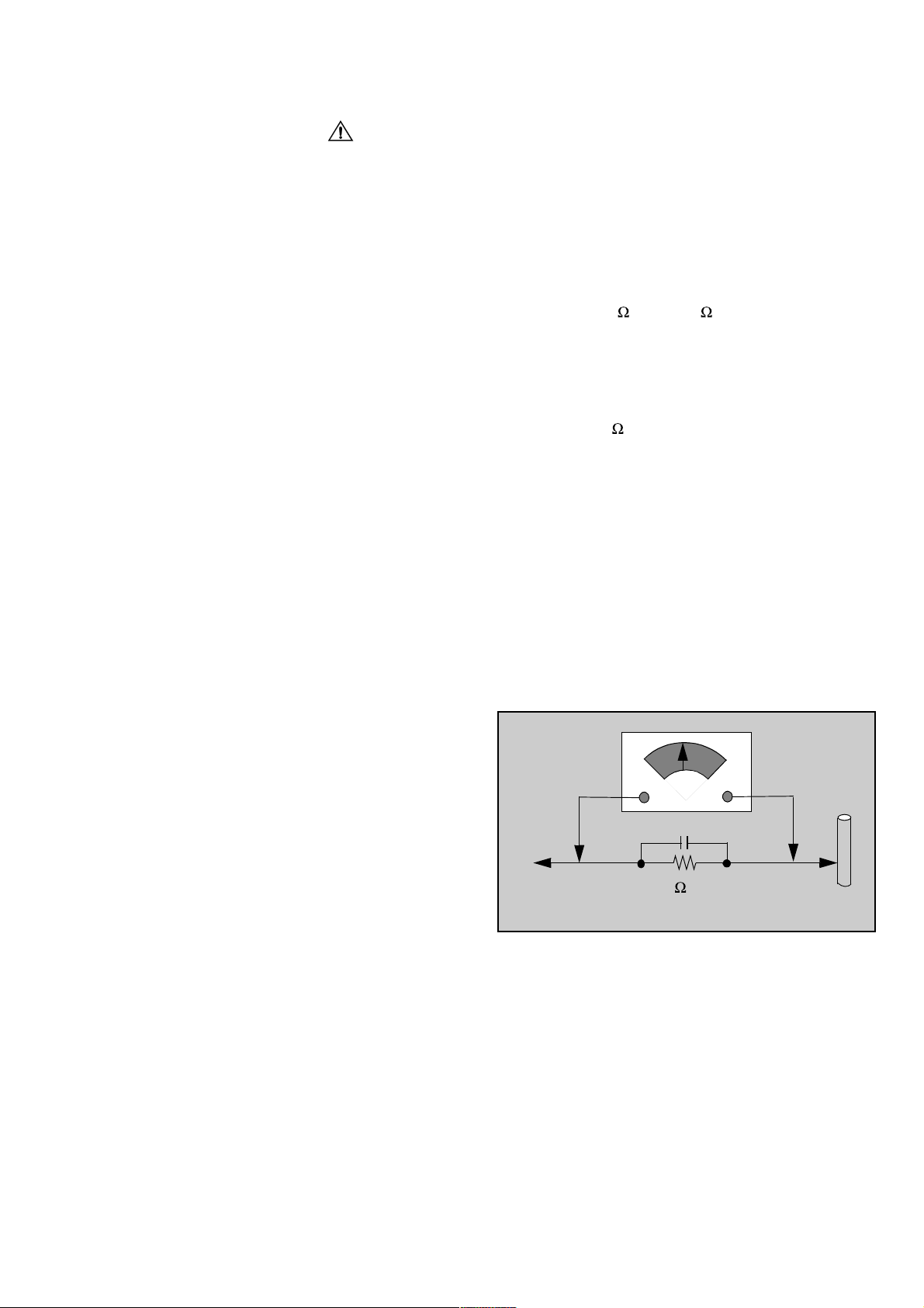
Leakage Current Hot Check (Fig. 1)
Plug the AC cord directly into the AC outlet. Do not use
an isolation transformer during the check.
Connect a 1.5k 10 watt resistor in parallel with a
0.15µF capacitor between an exposed metallic part and
ground. Use earth ground, for example a water pipe.
Using a DVM with a 1000 ohms/volt sensitivity or higher,
measure the AC potential across the resistor.
Repeat the procedure and measure the voltage present
with all other exposed metallic parts.
Verify that any potential does not exceed 0.75 volt RMS.
A leakage current tester (such a Simpson Model 229,
Sencore Model PR57 or equivalent) may be used in the
above procedure, in which case any current measure
must not exceed 0.5 milliamp. If any measurement is out
of the specified limits, there is a possibility of a shock
hazard and the Receiver must be repaired and
rechecked before it is returned to the customer.
AC VOLTMETER
COLD
WATER
PIPE
(GROUND)
0.15µF
TO INSTRUMENT’S
EXPOSED METAL
PARTS
1500 ,10 W
Figure 1.
Hot Check Circuit
X-ray Radiation
WARNING: The potential source of X-ray radiation in
the TV set is in the High Voltage section and the picture
Note:
Set the brightness and picture controls to Minimum.
Measure the High Voltage. The high voltage should be
24.5 ± 1.0kV. If the upper limit is out of tolerance,
immediate service and correction is required to insure
safe operation and to prevent the possibility of
premature component failure.
It is important to use an accurate, calibrated high
voltage meter.
A2-1

Service Notes
These components are affixed with glue. Be careful not to break or damage any foil under the
Note:
component or at the pins of the ICs when removing. Usually applying heat to the component for a
short time while twisting with tweezers will break the component loose.
Leadless Chip Component
(surface mount)
Chip components must be replaced with identical chips
due to critical foil track spacing. There are no holes in
the board to mount standard transistors or diodes. Some
chips capacitor or resistor board solder pads may have
holes through the board, however the hole diameter limits
standard resistor replacement to 1/8 watt. Standard
capacitor may also be limited for the same reason. It is
recommended that identical components be used.
Chip resistor have a three digit numerical resistance code
- 1st and 2nd significant digits and a multiplier.
Example: 162 = 1600 or 1.6k resistor, 0 = 0 (jumper).
Chip capacitors generally do not have the value indicated
on the capacitor. The color of the component indicates the
general range of the capacitance.
Chip transistors are identified by a two letter code. The
first letter indicates the type and the second letter, the
grade of transistor.
Chip diodes have a two letter identification code as per the
code chart and are a dual diode pack with either common
anode or common cathode. Check the parts list for correct
diode number.
Component Removal
Use solder wick to remove solder from component end
1.
caps or terminal.
Without pulling up, carefully twist the component with
2.
tweezers to break the adhesive.
Do not reuse removed leadless or chip components
3.
since they are subject to stress fracture during
removal.
Chip Component Installation
1.2.Put a small amount of solder on the board soldering
pads.
Hold the chip component against the soldering pads
with tweezers or with a miniature alligator clip and
apply heat to the pad area with a 30 watt iron until
solder flows. Do not apply heat for more than 3
seconds.
Chip Components
TYPE
B
ANODES
E
TRANSISTOR
GRADE
C
COMMON
CATHODE
SOLDER
CAPS
CAPACITOR
1ST DIGIT
RESISTORMH DIODE
SOLDER
CAPS
2ND DIGIT
MULTIPLIER
=1600 = 1.6k
A2-2
How to Replace Flat-IC
- Required Tools -
Soldering iron De-solder braids
Needle nose pliers Magnifier
Wire cutters (sharp & small)
Cut the pins of a defective IC with wire cutters.
1.
Remove IC from board. If IC is glued to the board,
heat the IC and release the IC. See Note above.
Flat IC
Using soldering iron and needle nose pliers remove
2.
the IC pins from the board.
Soldering
Iron
Using de-soldering braid and soldering iron remove
3.
solder from affected are on board (pads).
De-soldering
Braid
Soldering
Iron
Position the new Flat-IC in place (apply the pins of
4.
the Flat-IC to the soldering pads where the pins
need to be soldered). Determine the positions of
the soldering pads and pins by correctly aligning
the polarity symbol. Solder pin #1 first, align the IC.
Polarity
symbol
Solder the pin opposite to pin #1. This will assist
positioning the IC.
5.
Solder all pins to the soldering pads using a fine
tipped soldering iron.
Solder
Check with a magnifier for solder bridge between
6.
the pins or for dry joint between pins and soldering
pads. To remove a solder bridge, use a de-solder
braid as shown in the figure below.
Solder
Bridge
2nd solder
De-Solder
Braid
1st solder
Soldering
Iron
Soldering
lron

Service Notes (Continued)
IMPORTANT: To protect against possible damage to the
solid state devices due to arcing or static discharge, make
certain that all ground wires and CTR DAG wire are
securely connected.
CAUTION: The power supply circuit is above earth
ground and the chassis cannot be polarized. Use an
isolation transformer when servicing the Receiver to avoid
damage to the test equipment or to the chassis. Connect
the test equipment to the proper ground ( ) or ( ) when
servicing, or incorrect voltages will be measured.
WARNING: This Receiver has been designed to meet
or exceed applicable safety and X-ray radiation
protection as specified by government agencies and
independent testing laboratories.
To maintain original product safety design standards
relative to X-ray radiation and shock and fire hazard,
parts indicated with the symbol on the schematic
must be replaced with identical parts. Order parts from
the manufacturer’s parts center using the parts
numbers shown in this service manual, or provide the
chassis number and the part reference number.
For optimum performance and reliability, all other parts
should be replaced with components of identical
specification.
A2-3
 Loading...