

Panasonic CS-YC9MKV, CS-YC12MKV, CS-YC12MKV-6, CS-YC9MKV-7, CS-YC12MKV-7 Service Manual
...
© Panasonic Home Appliances Air-Conditioning
(Guangzhou) Co.,Ltd (PHAAG) 2010. All rights
reserved. Unauthorized copying and distribution is a
violation of law.
Order No: PHA-AG1101002C3
Indoor Unit Outdoor Unit
CS-YC9MKV
CS-YC12MKV
CS-YC12MKV-6
CS-YC9MKV-7
CS-YC12MKV-7
CU-YC9MKV
CU-YC12MKV
CU-YC12MKV-6
CU-YC9MKV-7
CU-YC12MKV-7
TABLE OF CONTENTS
1. Safety Precautions.............................................3
2. Specification.......................................................5
2.1 CS/CU-YC9MKV, CS/CU-YC12MKV...........5
2.2 CS/CU-YC9MKV-7, CS/CU-YC12MKV-7....7
2.3 CS/CU-YC12MKV-6.....................................9
3. Location of Controls and Components .........11
3.1 Indoor Unit..................................................11
3.2 Outdoor Unit...............................................11
3.3 Remote Control..........................................11
4. Dimensions.......................................................12
4.1 Indoor Unit..................................................12
4.2 Outdoor Unit...............................................13
5. Refrigeration Cycle Diagram...........................14
6. Block Diagram..................................................15
7. Wiring Connection Diagram............................16
7.1 Indoor unit ..................................................16
7.2 Outdoor Unit...............................................17
8. Installation Instruction.....................................18
8.1 Select The Best Location...........................18
8.2 Indoor Unit..................................................19
8.3 Outdoor Unit...............................................22
9. Operation Control.............................................24
9.1 Cooling Operation ......................................24
9.2 Soft Dry Operation......................................25
9.3 Automatic operation...................................25
9.4 Indoor Fan Speed Control..........................26
9.5 Outdoor Fan Speed Control.......................27
9.6 Vertical Airflow Direction Control................27
WARNING
This service information is designed for experienced repair technicians only and is not designed for use by the general public.
It does not contain warnings or cautions to advise non-technical individuals of potential dangers in attempting to service a product.
Products powered by electricity should be serviced or repaired only by experienced professional technicians. Any attempt to
service or repair the products dealt with in this service information by anyone else could result in serious injury or death.

2
9.7
Horizontal Airflow Direction Control............27
9.8 Timer Control..............................................27
9.9 Random Auto Restart Control....................27
10. Protection Control............................................28
10.1 Restart Control (Time Delay Safety Control)
28
10.2 7 minutes Time Save Control.....................28
10.3 60 seconds Forced Operation....................28
10.4 30 Seconds Forced Operation ...................28
10.5 Anti-Freezing Control .................................28
10.6 Compressor Reverse Rotation Protection
Control...................................................................28
10.7 Dew Prevention Control .............................29
11. Servicing Mode.................................................30
11.1 Auto Off/On Button.....................................30
11.2 Remote Control Button...............................30
12. Troubleshooting Guide....................................31
12.1 Refrigeration Cycle System........................31
Diagnosis methods of a malfunction of a
compressor .............................................................32
13. Disassembly and Assembly Instructions ......33
14. Exploded View and Replacement Pars List...36
14.1 Indoor Unit..................................................36
14.2 Outdoor Unit...............................................39
3
CAUTION
WARNING
WARNING
1. Safety Precautions
• Read the following “SAFETY PRECAUTIONS” carefully before perform any servicing.
• Electrical work must be installed or serviced by a licensed electrician. Be sure to use the correct rating of the
power plug and main circuit for the model installed.
• The caution items stated here must be followed because these important contents are related to safety. The
meaning of each indication used is as below. Incorrect installation or servicing due to ignoring of the instruction
will cause harm or damage, and the seriousness is classified by the following indications.
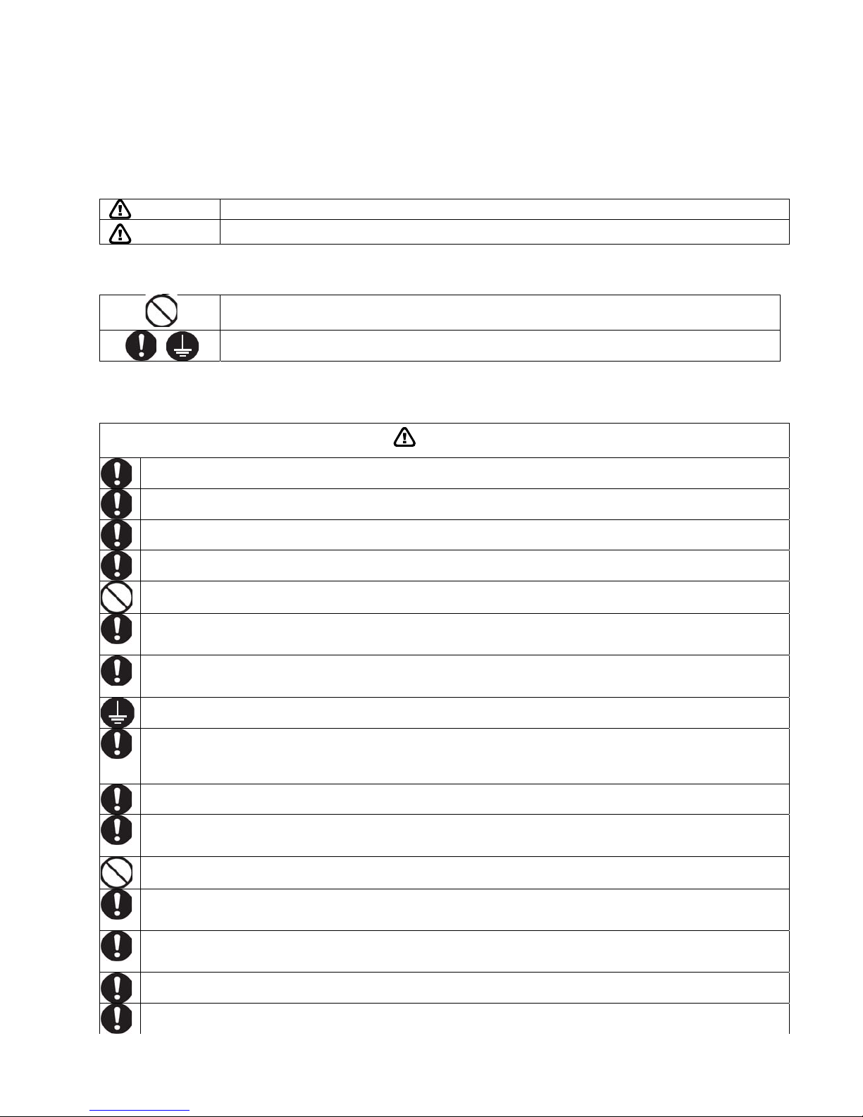
This indication shows the possibility of causing death or serious injury
This indication shows the possibility of causing injury or damage to properties.
• The items to be followed are classified by the symbols:
• Carry out test run to confirm that no abnormality occurs after the servicing. Then, explain to user the operation,
care and maintenance as stated in instructions. Please remind the customer to keep the operating instructions for
future reference.
1. Engage dealer or specialist for installation. If installation done by the user is defective, it will cause water leakage,
electrical shock or fire.
2. Install according to this installation instructions strictly. If installation is defective, it will cause water leakage, electrical
shock or fire.
3. Use the attached accessories parts and specified parts for installation. Otherwise, it will cause the set to fall, water
leakage, fire or electrical shock.
4. Install at a strong and firm location which is able to withstand the set’s weight. If the strength is not enough or
installation is not properly done, the set will drop and cause injury.
5. Do not install outdoor unit near handrail of veranda. When installing air-conditioner unit at veranda of high rise
building, child may climb up to outdoor unit and cross over the handrail and causing accident.
6. For electrical work, follow the local national wiring standard, regulation and this installation instruction. An independent
circuit and single outlet must be used. If electrical circuit capacity is not enough or defect found in electrical work, it will
cause electrical shock or fire.
7. This equipment is strongly recommended to be installed with Earth Leakage Circuit Breaker (ELCB) or Residual
Current Device (RCD). Otherwise, it may cause electrical shock and fire in case equipment breakdown or insulation
breakdown.
8. This equipment must be properly earthed. Earth line must not be connected to gas pipe, water pipe, earth of lightning
rod and telephone. Otherwise, it may cause electrical shock in case equipment breakdown or insulation breakdown.
9. Do not use joint cable for indoor/outdoor connectio n cable. Use the specifi ed Indoor/Outdoor connection cable, refer
to installation instructions CONNECT THE CABLE TO THE INDOOR UNIT and connect tightly for indoor / outdoor
connection. Clamp the cable so that no external force will be acted on the terminal. If connection or fixing is not
perfect, it will cause heat up or fire at the connection.
10. Wire routing must be properly arranged so that control board cover is fixed properly. If control board cover is not fixed
perfectly, it will cause fire or electrical shock.
11. When carrying out piping connection, take care not to let air substances other than the specified refrigerant go into
refrigeration cycle. Otherwise, it will cause lower capacity, abnormal high pressure in the refrigeration c yc le, explosion
and injury.
12. Do not use unspecified cord, modified cord, joint cord or extension cord for power supply cord. Do not share the single
outlet with other appliances. Poor contact, poor insulation or over current will cause electrical shock or fire.
13. During installation, install the refrigerant piping properly before run the compressor. Operation of compressor without
fixing refrigeration piping and valves at opened conditi on will cause suck-in of air, abnormal high pressure in
refrigeration cycle and result in explosion, injury etc.
14. During pump down operation, stop the compressor before remove the refrigeration piping. Removal of refriger ation
piping while compressor is operating and valves are opened will cause suck-in of air, abnormal high pressure in
refrigeration cycle and result in explosion, injury etc.
15. After completion of installation or service, confirm there is no leakage of refrigerant gas. It may generate toxic gas
when the refrigerant contacts with fire.
16. Ventilate if there is refrigerant gas leakage during operation. It may cause toxic gas when the refrigerant contacts with
fire.
Symbol with white background denotes item that is PROHIBITED from doing.
Symbol with dark background denotes item that must be carried out.
4
CAUTION
17. Recommended installation height for indoor unit shall be at least 2.5 m.
18. The appliance shall be installed in accordance with national wiring regulations.
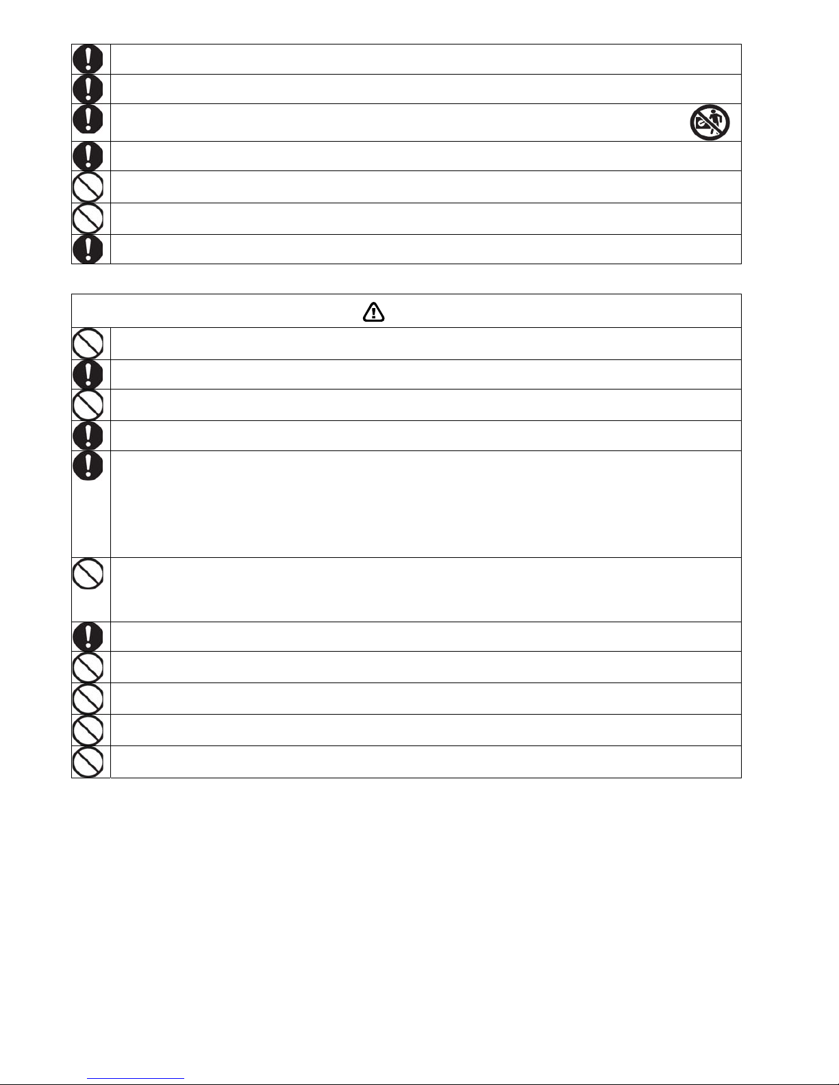
19. Keep away from small children, the thin film may cling to nose and mouth and prevent breathing.
20. Tighten the flare nut with torque wrench according to specified method. If the flare nut is over-tightened, after a long
period, the flare may break and cause refrigerant gas leakage.
22. Do not insert your fingers or other objects into the unit, high speed rotating fan may cause injury.
23. Do not modify the machine, part, material during repairing service.
24. Must not use other parts except original parts describe in catalog and manual.
1. Do not install the unit at place where leakage of flammable gas may occur. In case gas leaks and accumulates at
surrounding of the unit, it may cause fire.
2. Carry out drainage piping as mentioned in installation instructions. If drainage is not perfect, water may enter the room
and damage the furniture.
3. Do not touch outdoor unit air inlet and aluminums fin. It may cause injury.
4. Select an installation location which is easy for maintenance.
5. Power supply connection to the air conditioner.
Connect the power supply cord of the air conditioner to the mains using one of the following methods.
Power supply point should be in easily accessible place for power disconnection in case of emergency.
In some countries, permanent connection of this air conditioner to the power supply is prohibited.
1) Power supply connection to the receptacle using a power plug.
Use an approved 15/16A power plug with earth pin for the connection to the receptacle.
2) Power supply connection to a circuit breaker for the permanent connection. Use an approved 16A circuit breaker for
the permanent connection. It must be a double pole switch with a minimum 3.5 mm contact gap.
6. Do not release refrigerant.
Do not release refrigerant during piping work for installation, re-installation and during repairing a refrigeration parts.
Take care of the liquid refrigerant, it may cause frostbite.
7. Installation or servicing work.
It may need two people to carry out the installation and service work.
8. Do not install this appliance in a laundry room or other location where water may drip from the ceiling, etc.
9. Do not sit ot step on the unit, you may fall down accidentally.
10. Do not touch the sharp aluminium fin, sharp parts may cause injury.
11. Thermal fuse specification for indoor unit: 250V 3.15A T3.15AL.
5
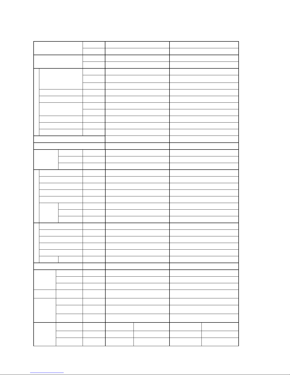
2. Specification
2.1 CS/CU-YC9MKV, CS/CU-YC12MKV
Indoor CS-YC9MKV CS-YC12MKV
Model
Outdoor CU-YC9MKV CU-YC12MKV
Phase, Hz Single, 60 Single, 60
Power Supply
V 220 220
kW 2.64 3.52
BTU/h 9000 12000
Capacity
kJ/h 2270 3027
Running Current A 4.30 5.50
Input Power W 900 1180
W/W 2.93 2.98
EER
Btu/hW 10.00 10.17
Power Factor % 95 97
Indoor Noise (H / L ) dB-A 37 / 30 / 39 / 33 /
Cooling
Outdoor Noise (H / L) dB-A 49 / - 49 / -
Max Current (A) / Max Input Power (W) 5.90 / 1.130k 7.40 / 1.450k
Starting Current (A) 25.0 34.0
Type Hermetic Motor Hermetic Motor
Motor Type Induction (2 poles) Induction (2 poles)
Compressor
Output Power W 750 1.100k
Type Cross-flow fan Cross-flow fan
Material AS AS
Motor Type Induction (4 poles) Induction (4 poles)
Input Power W - -
Output Power W 20 20
Lo rpm 780 850
Me rpm 880 960
Indoor Fan
Hi rpm 1010 1060
Type Propeller Propeller
Material PP PP
Motor Type Induction (6 poles) Induction (6 poles)
Input Power W - -
Output Power W 28 28
Outdoor Fan
Speed Hi rpm 840 880
Moisture Removal L/h (Pt/h) 1.5 (2.6) 2.0 (3.4)
Lo m3/min (ft3/m) 8.9 (315) 9.8 (347)
Me m3/min (ft3/m) 10.1 (355) 11.6 (392)
Indoor Airflow
Hi m
3
/min (ft3/m) 11.6 (408) 12.3 (433)
Outdoor
Airflow
Hi m
3
/min (ft3/m) 26.8 (948) 26.8 (948)
Control Device Capillary Tube Capillary Tube
Refrigerant Oil cm3
ATMOS M60 OR SUNISO 4GDID
(290)
ATMOS NM56 OR SUNISO 4GDID (350)
Refrigeration
Cycle
Refrigerant
Type
g (oz) R22, 550 (19.3) R22, 820 (28.9)
Height(I/D /
O/D)
mm (inch) 283 (11-5/32) 530(20-7/8) 283 (11-5/32) 530 (20-7/8)
Width (I/D / O/D) mm (inch) 803 (31-5/8) 650(25-19/32) 803 (31-5/8) 650 (25-19/32)
Dimension
Depth (I/D /
O/D)
mm (inch) 214 (8-7/16) 230 (9-1/16) 214 (8-7/16) 230 (9-1/16)

6
Weight Net (I/D / O/D) kg (lb) 8.0 (18) 21 (46) 8.0 (18) 26 (57)
Pipe Diameter (Liquid /
Gas)
mm (inch) 6.35 (1/4) / 9.52 (3/8) 6.35 (1/4) / 12.70 (1/2)
Standard length m (ft) 5.0 (16.4) 5.0 (16.4)
Length range (min – max) m (ft) 3 (9.8) ~15 (49.2) 3 (9.8) ~ 15(49.2)
I/D & O/D Height different m (ft) 5.0 (16.4) 5.0 (16.4)
Additional Gas Amount g/m (oz/ft) 20 (0.2) 20 (0.2)
Piping
Length for Additional Gas m (ft) 5.0 (16.4) 5.0 (16.4)
Inner Diameter mm 16 16
Drain Hose
Length mm 500 500
Fin Material Pre coated Pre coated
Fin Type Slit Fin Slit Fin
Row x Stage x
FPI
2 x 16 x 19 2 x 16 x 19
Indoor Heat
Exchanger
Size (W x H x L) mm 610 x 336 x 25.4 610 x 315 x 25.4
Fin Material Bear Fin Bear Fin
Fin Type Slit Fin Slit Fin
Row x Stage x
FPI
1 x 24 x 18 2 x 24 x 18
Outdoor
Heat
Exchanger
Size (W x H xD) mm 570.7 x504.0 x 12.7 565.2(545.3) x 504.0 x 12.7
Material P.P.HONEY COMB P.P.HONEY COMB
Air Filter
Type One-touch One-touch
Power Supply Indoor Indoor
Power Supply Cord A 10 10
Thermostat - -
Protection Device - -
DRY BULB WET BULB DRY BULB WET BULB
Maximum 32 23 32 23
Indoor Operation Range
Minimum 16 11 16 11
Maximum 43 26 43 26
Outdoor Operation Range
Minimum 16 11 16 11
1. Cooling capacities are based on indoor temperature of 27°C DRY BULB (80.6°F DRY BULB), 19.0°C WET BULB (66°F WET BULB) and
outdoor air temperature of 35°C DRY BULB (95°F DRY BULB), 24°C WET BULB (75.2°F WET BULB)
7
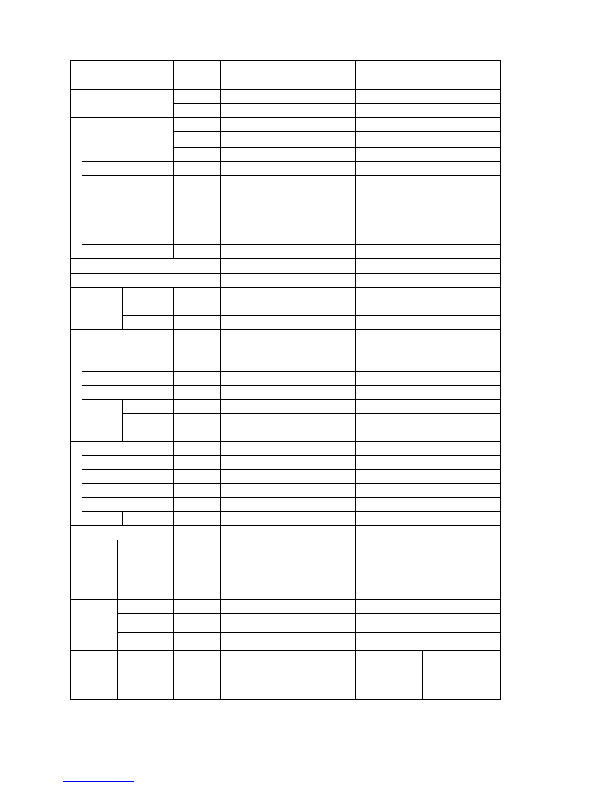
2.2 CS/CU-YC9MKV-7, CS/CU-YC12MKV-7
Indoor CS-YC9MKV-7 CS-YC12MKV-7
Model
Outdoor CU-YC9MKV-7 CU-YC12MKV-7
Phase, Hz Single, 60 Single, 60
Power Supply
V 220 220
kW 2.64 3.52
BTU/h 9000 12000
Capacity
kJ/h 2270 3027
Running Current A 4.30 5.50
Input Power W 900 1180
W/W 2.93 2.98
EER
Btu/hW 10.00 10.17
Power Factor % 95 97
Indoor Noise (H / L ) dB-A 37 / 30 / 39 / 33 /
Cooling
Outdoor Noise (H / L) dB-A 49 / - 49 / -
Max Current (A) / Max Input Power (W) 5.90 / 1.130k 7.40 / 1.450k
Starting Current (A) 25.0 34.0
Type Hermetic Motor Hermetic Motor
Motor Type Induction (2 poles) Induction (2 poles)
Compressor
Output Power W 750 1.100k
Type Cross-flow fan Cross-flow fan
Material AS AS
Motor Type Induction (4 poles) Induction (4 poles)
Input Power W - -
Output Power W 20 20
Lo rpm 780 850
Me rpm 880 960
Indoor Fan
Hi rpm 1010 1060
Type Propeller Propeller
Material PP PP
Motor Type Induction (6 poles) Induction (6 poles)
Input Power W - -
Output Power W 28 28
Outdoor Fan
Speed Hi rpm 840 880
Moisture Removal L/h (Pt/h) 1.5 (2.6) 2.0 (3.4)
Lo m3/min (ft3/m) 8.9 (315) 9.8 (347)
Me m3/min (ft3/m) 10.1 (355) 11.6 (392)
Indoor Airflow
Hi m
3
/min (ft3/m) 11.6 (408) 12.3 (433)
Outdoor
Airflow
Hi m
3
/min (ft3/m) 26.8 (948) 26.8 (948)
Control Device Capillary Tube Capillary Tube
Refrigerant Oil cm3
ATMOS M60 OR SUNISO 4GDID
(290)
ATMOS NM56 OR SUNISO 4GDID (350)
Refrigeration
Cycle
Refrigerant
Type
g (oz) R22, 550 (19.3) R22, 820 (28.9)
Height(I/D /
O/D)
mm (inch) 283 (11-5/32) 530(20-7/8) 283 (11-5/32) 530 (20-7/8)
Width (I/D / O/D) mm (inch) 803 (31-5/8) 650(25-19/32) 803 (31-5/8) 650 (25-19/32)
Dimension
Depth (I/D /
O/D)
mm (inch) 214 (8-7/16) 230 (9-1/16) 214 (8-7/16) 230 (9-1/16)
8
Weight Net (I/D / O/D) kg (lb) 8.0 (18) 21 (46) 8.0 (18) 26 (57)
Pipe Diameter (Liquid /
Gas)
mm (inch) 6.35 (1/4) / 9.52 (3/8) 6.35 (1/4) / 12.70 (1/2)
Standard length m (ft) 5.0 (16.4) 5.0 (16.4)
Length range (min – max) m (ft) 3 (9.8) ~15 (49.2) 3 (9.8) ~ 15(49.2)
I/D & O/D Height different m (ft) 5.0 (16.4) 5.0 (16.4)
Additional Gas Amount g/m (oz/ft) 20 (0.2) 20 (0.2)
Piping
Length for Additional Gas m (ft) 5.0 (16.4) 5.0 (16.4)
Inner Diameter mm 16 16
Drain Hose
Length mm 500 500
Fin Material Pre coated Pre coated
Fin Type Slit Fin Slit Fin
Row x Stage x
FPI
2 x 16 x 19 2 x 16 x 19
Indoor Heat
Exchanger
Size (W x H x L) mm 610 x 336 x 25.4 610 x 315 x 25.4
Fin Material Bear Fin Bear Fin
Fin Type Slit Fin Slit Fin
Row x Stage x
FPI
1 x 24 x 18 2 x 24 x 18
Outdoor
Heat
Exchanger
Size (W x H xD) mm 570.7 x504.0 x 12.7 565.2(545.3) x 504.0 x 12.7
Material P.P.HONEY COMB P.P.HONEY COMB
Air Filter
Type One-touch One-touch
Power Supply Indoor Indoor
Power Supply Cord A 10 10
Thermostat - -
Protection Device - -
DRY BULB WET BULB DRY BULB WET BULB
Maximum 32 23 32 23
Indoor Operation Range
Minimum 16 11 16 11
Maximum 43 26 43 26
Outdoor Operation Range
Minimum 16 11 16 11
2. Cooling capacities are based on indoor temperature of 27°C DRY BULB (80.6°F DRY BULB), 19.0°C WET BULB (66°F WET BULB) and
outdoor air temperature of 35°C DRY BULB (95°F DRY BULB), 24°C WET BULB (75.2°F WET BULB)
9
2.3 CS/CU-YC12MKV-6
Indoor CS-YC12MKV-6
Model
Outdoor CU-YC12MKV-6
Phase, Hz Single, 60
Power Supply
V 220
kW 3.52
BTU/h 12000
Capacity
kJ/h 3027
Running Current A 5.50
Input Power W 1180
W/W 2.98
EER
Btu/hW 10.17
Power Factor % 97
Indoor Noise (H / L / QLo) dB-A 39 / 33 / -
Cooling
Outdoor Noise (H / L) dB-A 49 / -
Max Current (A) / Max Input Power (W) 7.40 / 1.450k
Starting Current (A) 34.0
Type Hermetic Motor
Motor Type Induction (2 poles)
Compressor
Output Power W 1100
Type Cross-flow fan
Material AS
Motor Type Induction (4-poles)
Input Power W -
Output Power W 20
Lo rpm 850
Me rpm 960
Indoor Fan
Indoor
Airflow
Hi rpm 1060
Type Propeller
Material PP
Motor Type Induction (6 poles)
Input Power W -
Output Power W 28
Outdoor Fan
Speed Hi rpm 880
Moisture Removal L/h (Pt/h) 2.0 (3.4)
Lo
m
3
/min
(ft
3
/m)
9.8 (347)
Me
m
3
/min
(ft
3
/m)
11.6 (392)
Indoor Airflow
Hi
m
3
/min
(ft
3
/m)
12.3 (433)
Outdoor
Airflow
Hi
m
3
/min
(ft
3
/m)
26.8 (948)
Control Device Capillary tube
Refrigerant Oil cm3 ATMOS NM56 OR SUNISO 4GDID (350)
Refrigeration
Cycle
Refrigerant Type g (oz) R22, 820 (28.9)
10
Height(I/D / O/D) mm (inch) 283 (11-5/32) 530 (20-7/8)
Width (I/D / O/D) mm (inch) 803 (31-5/8) 650 (25-19/32)
Dimension
Depth (I/D / O/D) mm (inch) 214 (8-7/16) 230 (9-1/16)
Weight Net (I/D / O/D) kg (lb) 8.0 (18) 26 (57)
Pipe Diameter (Liquid / Gas) mm (inch) 6.35 (1/4) / 12.70 (1/2)
Standard length m (ft) 5.0 (16.4)
Length range (min – max) m (ft) 3 (9.8) ~ 15(49.2)
I/D & O/D Height different m (ft) 5.0 (16.4)
Additional Gas Amount g/m (oz/ft) 20 (0.2)
Piping
Length for Additional Gas m (ft) 5.0 (16.4)
Inner Diameter mm 16
Drain Hose
Length mm 500
Fin Material Pre coated
Fin Type Slit fin
Row x Stage x FPI 2 x 16 x 19
Indoor Heat
Exchanger
Size (W x H x L) mm 610 x 315 x 25.4
Fin Material Bear Fin
Fin Type Slit Fin
Row x Stage x FPI 2 x 24 x 18
Outdoor
Heat
Exchanger
Size (W x H x L) mm 565.2(545.3) x 504.0 x 12.7
Material P.P.HONEY COMB
Air Filter
Type One-touch
Power Supply Indoor
Power Supply Cord A 10
Thermostat -
Protection Device -
DRY BULB WET BULB
Maximum 32 23
Indoor Operation Range
Minimum 16 11
Maximum 43 26
Outdoor Operation Range
Minimum 16 11
1. Cooling capacities are based on indoor temperature of 27°C DRY BULB (80.6°F DRY BULB), 19.0°C WET BULB (66°F WET BULB) and
outdoor air temperature of 35°C DRY BULB (95°F DRY BULB), 24°C WET BULB (75.2°F WET BULB)
11
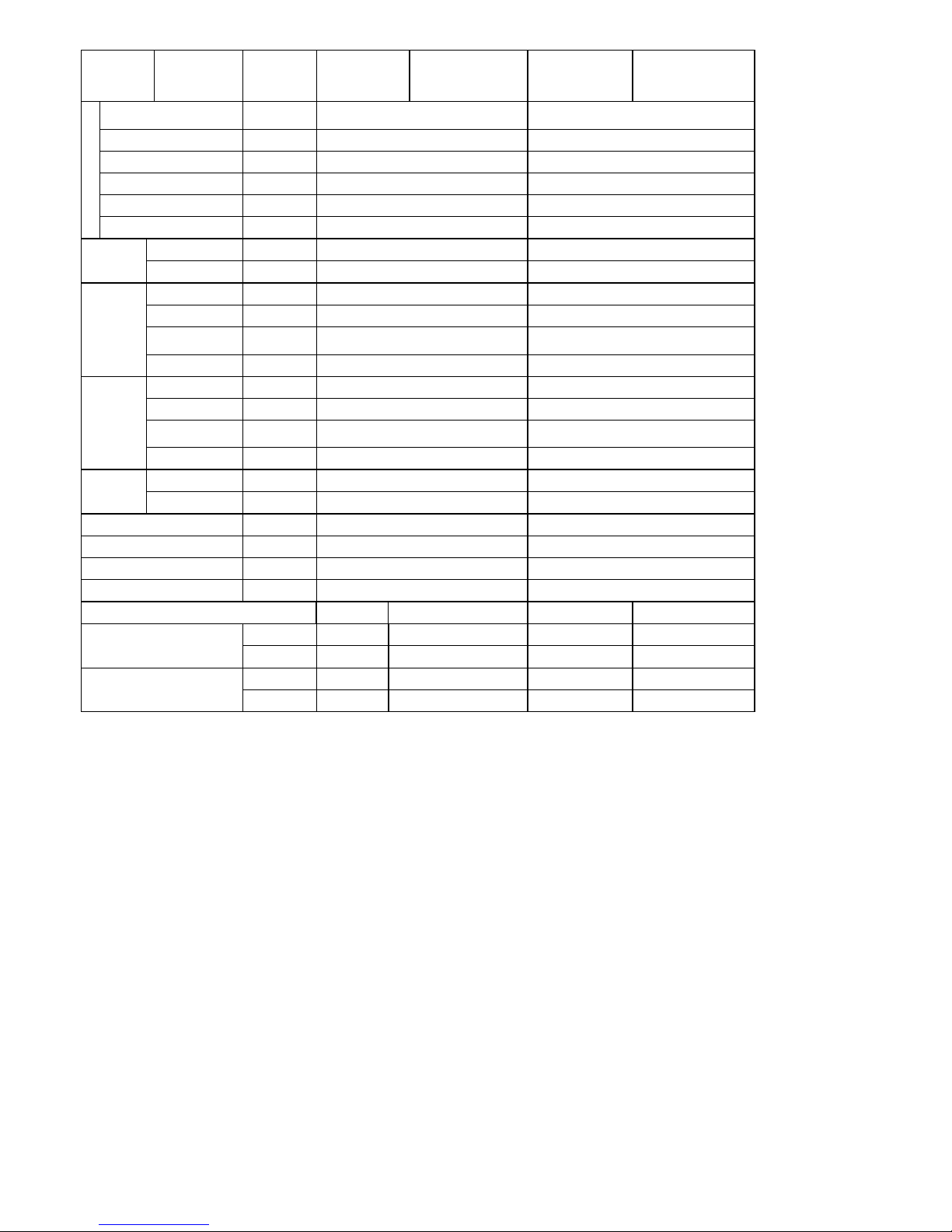
3. Location of Controls and Components
3.1 Indoor Unit
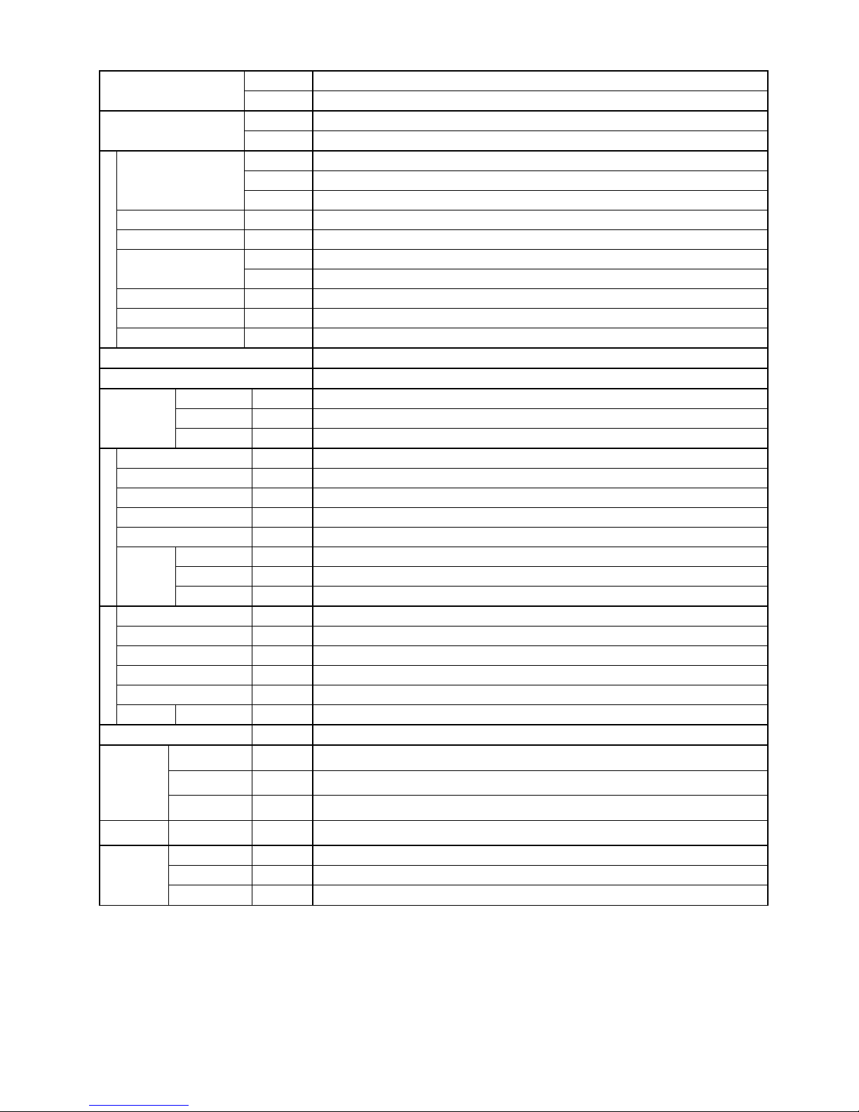
3.2 Outdoor Unit
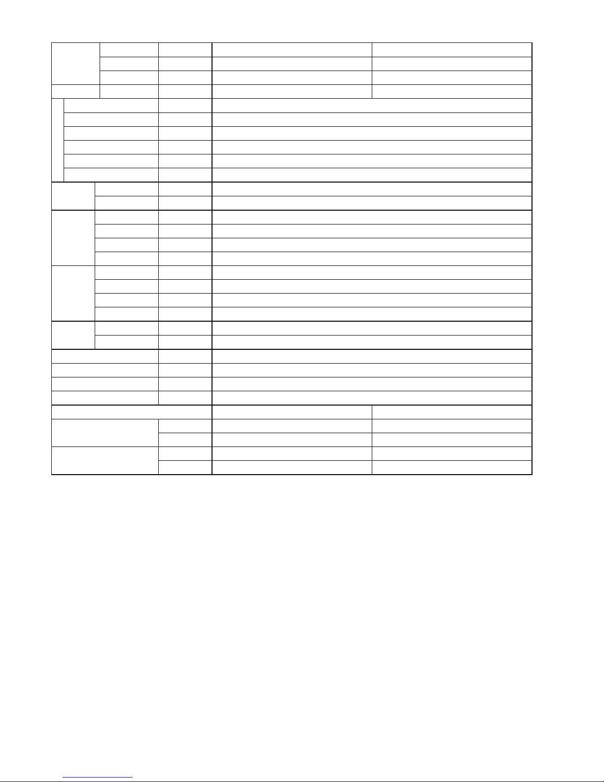
3.3 Remote Control
12
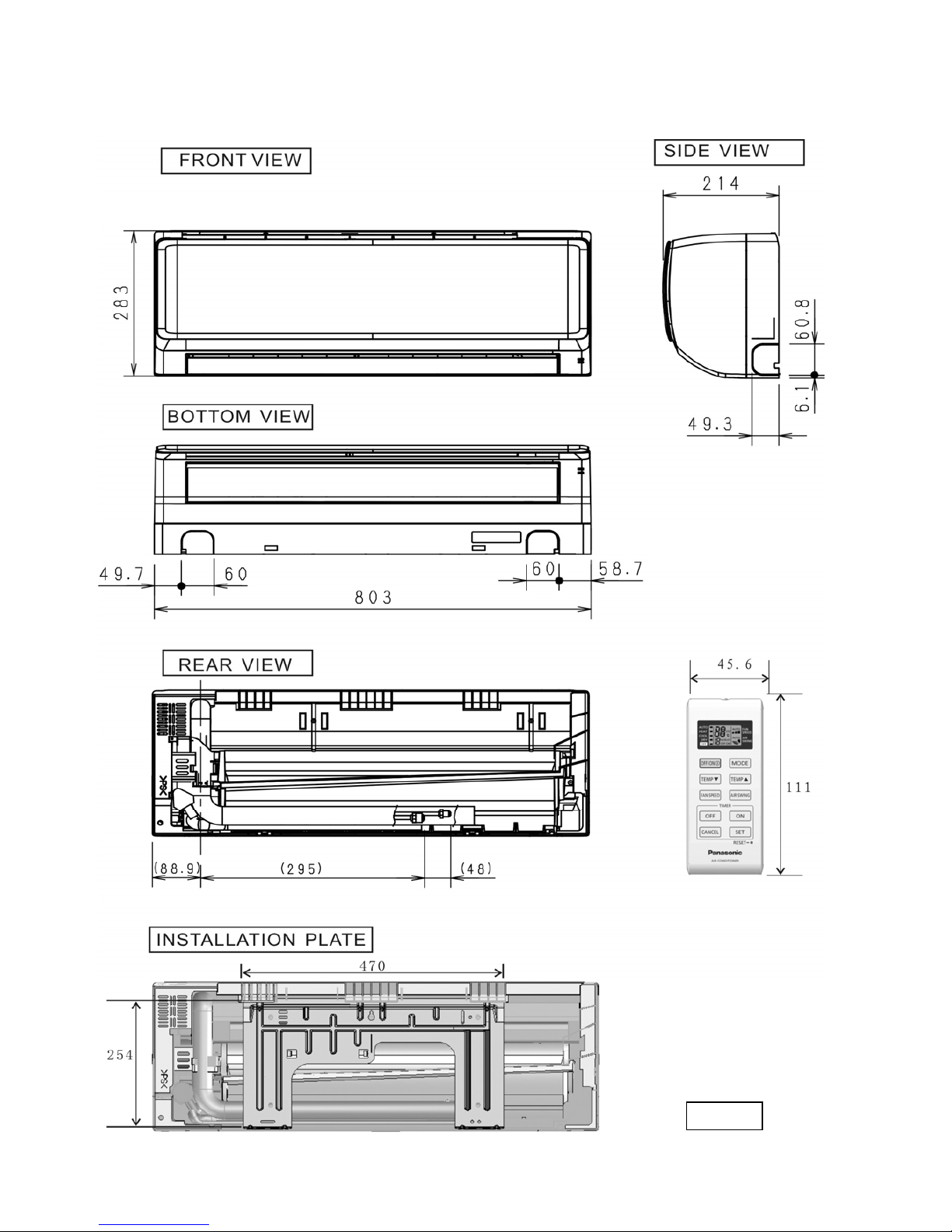
4. Dimensions
4.1 Indoor Unit
Unit : mm

13
4.2 Outdoor Unit
 Loading...