

Panasonic CS-VA70KE, CS-VA90KE, CU-VA70KE, CU-VA90KE, CS-VA120KE Service Manual
...
© 1999 Matsushita Electric Industrial Co., Ltd. All
rights reserved. Unauthorized copying and
distribution is a violation of law.
CS-VA70KE
CU-VA70KE
CS-VA90KE
CU-VA90KE
CS-VA120KE
CU-VA120KE
Room Air Conditioners
Order number RAC9911056C2
1 Features 3
2 Functions
4
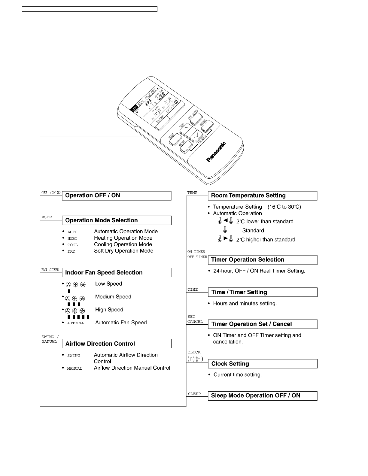
2.1. REMOTE CONTROL
4
2.2. INDOOR UNIT
5
2.3. OUTDOOR UNIT
6
3 Product Specifications
7
3.1. CS-VA70KE / CU-VA70KE
7
3.2. CS-VA90KE / CU-VA90KE
9
3.3. CS-VA120KE / CU-VA120KE
11
4 Dimensions
13
4.1. CS-VA70KE / CS-VA90KE / CS-VA120KE (INDOOR
UNIT)
13
4.2. CU-VA70KE / CU-VA90KE (OUTDOOR UNIT)
14
4.3. CU-VA120KE(OUTDOOR UNIT)
14
5 Refrigeration Cycle Diagram
15
5.1. CS-VA70KE / CU-VA70KE, CS-VA90KE / CU-VA90KE
15
5.2. CS-VA120KE / CU-VA120KE
16
6 Block Diagram
17
7 Wiring Diagram
18
8 Operation Details
19
8.1. COOLING MODE OPERATION
19
8.2. SOFT DRY MODE OPERATION
21
8.3. HEATING MODE OPERATION
23
8.4. AUTOMATIC MODE OPARATION
27
8.5. SLEEP MODE AUTO OPERATION
27
8.6. AUTO RESTART CONTROL
28
8.7. INDOOR FAN MOTOR CONTROL
28
8.8. AIRFLOW DIRECTION CONTROL
29
8.9. DELAY ON TIMER CONTROL
29
9 Installation And Servicing Air Conditioner Using R410A
30
9.1. OUTLINE
30
9.2. TOOLS FOR INSTALLING/SERVICING REFRIGERANT
PIPING
31
9.3. REFRIGERANT PIPING WORK
35
9.4. INSTALLATION, TRANSFERRING SERVICING
37
10 Installation Information
41
10.1. ATTACHED ACCESSORIES
41
10.2. SELECT THE BEST LOCATION
41
10.3. INDOOR/OUTDOOR UNIT INSTALLATION DIAGRAM
42
11 2-WAY / 3-WAY VALES
43
11.1. EVACUATION OF INSTALLATION
44
11.2. PUMPING DOWN
45
11.3. EVACUATION OF RE-INSTALLATION
46
11.4. BALANCE REFRIGERANT OF THE 2-WAY, 3-WAY
VALVE
47
11.5. EVACUATION
48
12 Servicing Information
49
12.1. INSPECTION POINTS FOR THE INDOOR ELECTRONIC
CONTROLLER
49
12.2. INDOOR FAN MOTOR REMOVAL PROCEDURE
49
12.3. CROSS FLOW FAN REMOVAL PROCEDURE
51
12.4. OUTDOOR UNIT SERVICING
52
12.5. REMOTE CONTROL RESET
52
12.6. CHANGING THE WIRELESS REMOTE CONTROL
TRANSMISSION CODE
53
13 Troubleshooting Guide
54
13.1. RELATIONSHIP BETWEEN THE CONDITION OF THE
AIR CONDITIONER AND GAS PRESSURE AND
ELECTRIC CURRENT
55
13.2. DIAGNOSIS METHODS OF A MALFUNNCTION OF A
COMPRESSOR AND A 4-WAY VALVE
55
14 Technical Data
56
14.1. THERMOSTAT CHARACTERISTICS
56
14.2. OPERATION CHARACTERISTICS
57
15 Electronic Circuit Diagram
60
15.1. HOW TO USE ELECTRONIC CIRCUIT DIAGRAM
60
15.2. ELECTRONIC CIRCUIT DIAGRAM
61
15.3. CHARACTERISTICS CHART
63
15.4. REMOTE CONTROLLER
64
15.5. TIMER TABLE
65
16 Printed Circuit Board
66
16.1. INDOOR UNIT (MAIN)
66
17 Exploded View & Replacement Parts List
67
17.1. CS-VA70KE / CS-VA90KE
67
17.2. CS-VA120KE
69
17.3. CU-VA70KE / CU-VA90KE
71
17.4. CU-VA120KE
73
18 Electronic Parts List
75
CONTENTS
Page Page
2
CS-VA70KE / CU-VA70KE / CS-VA90KE / CU-VA90KE / CS-VA120KE / CU-VA120KE

·
R410A
No Ozone Layer Damage
Our new models use R410A as its refrigerant.
This Refrigerant does not contain chlorine, so there´s no
danger of damage to the ozone layer.
·
Compact Design
·
Comfort Improvement
−
− −
−
Wider range of horizontal discharge air
−
− −
−
Longer hours of sleep mode operation
·
Auto Restart
−
− −
−
Auto restart operation after power failure
·
Removable and Washable Front Panel
·
Deodorizing Air Purifying Filter
−
− −
−
Air Purifying Filter features a deodorizing function that
removes unpleasant odors from the air.
·
Installation Work Improvement
−
− −
−
Long piping up to 10 m (CS-VA70KE / CS-VA90KE)
−
− −
−
Long piping up to 15 m (CS-VA120KE)
·
Quality Improvement
−
− −
−
Low voltage protection
−
− −
−
Gas leakage protection
−
− −
−
Prevent compressor reverse cycle
−
− −
−
2-stage OLP to protect compressor
(CS-VA90KE / CS-VA120KE)
·
Service Improvement
−
− −
−
Easy fan motor replacement procedure
−
− −
−
Front side servicing for outdoor unit
1 Features
3
CS-VA70KE / CU-VA70KE / CS-VA90KE / CU-VA90KE / CS-VA120KE / CU-VA120KE
2 Functions
2.1. REMOTE CONTROL
4
CS-VA70KE / CU-VA70KE / CS-VA90KE / CU-VA90KE / CS-VA120KE / CU-VA120KE
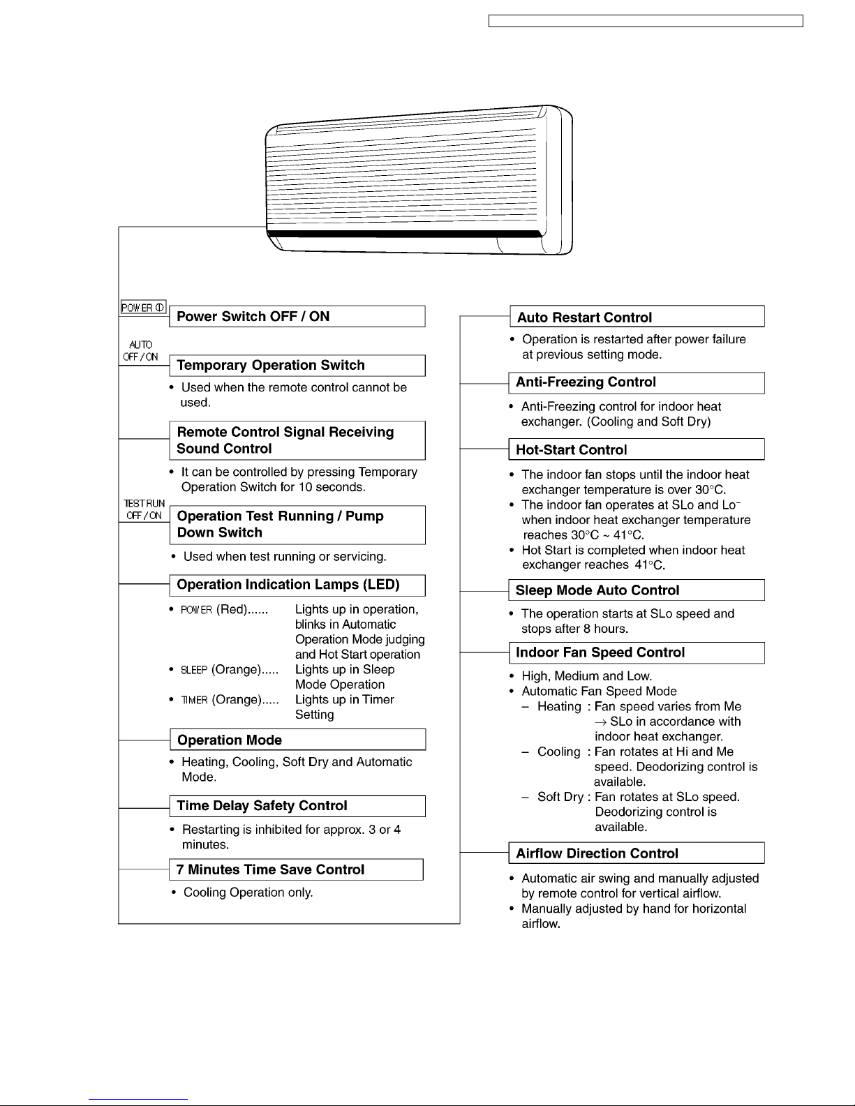
2.2. INDOOR UNIT
5
CS-VA70KE / CU-VA70KE / CS-VA90KE / CU-VA90KE / CS-VA120KE / CU-VA120KE
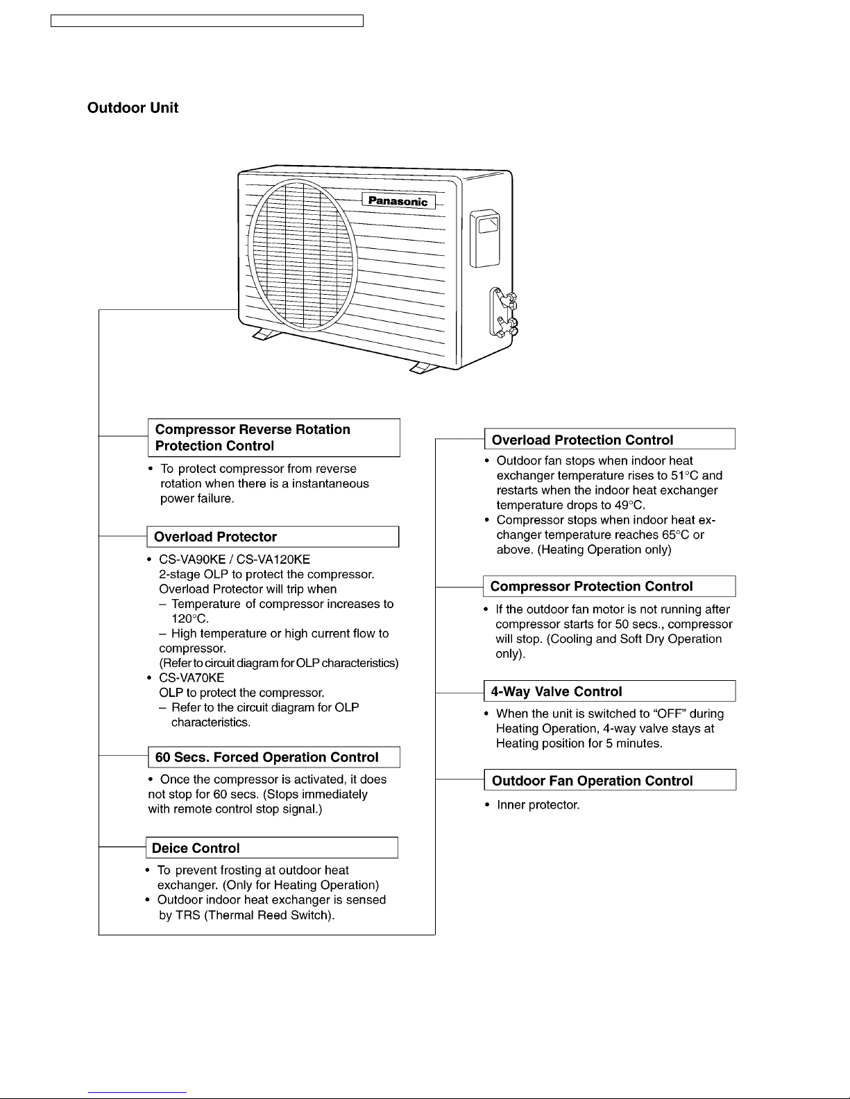
2.3. OUTDOOR UNIT
6
CS-VA70KE / CU-VA70KE / CS-VA90KE / CU-VA90KE / CS-VA120KE / CU-VA120 KE
3 Product Specifications
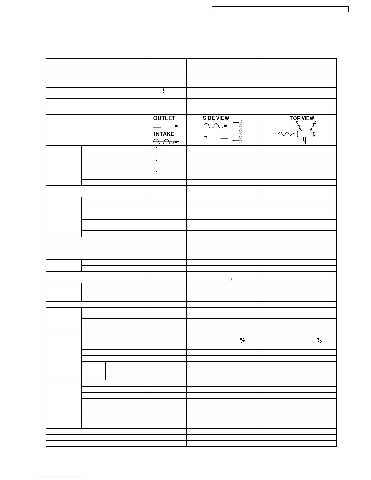
3.1. CS-VA70KE / CU-VA70KE
Unit CS-VA70KE CU-VA70KE
Cooling Capacity kW
Btu/h
2.20
7,500
Heating Capacity kW
Btu/h
2.35
8,000
Moisture Removal /h
Pint/h
1.3
2.7
Power Source Phase
V
Cycle
Single
230
50
Airflow Method
Air Volume Indoor Air(Lo) m / min(cfm) Cooling ; 5.5(190)
Heating ; 5.5(190)
-
Indoor Air(Me) m / min(cfm) Cooling ; 6.0(210)
Heating ; 6.0(210)
-
Indoor Air(Hi) m / min(cfm) Cooling ; 6.7(240)
Heating ; 6.7(240)
-
Outdoor Air m / min(cfm) - 22.4(790)
Noise Level dB(A) Cooling ; High 34,Low 30
heating ; High 33,Low 29
Cooling ; 46
Heating ; 48
Electrical
Data
Input kW Cooling ; 0.64
Heating ; 0.60
Running Current A Cooling ; 3.2
Heating ; 3.0
COP Cooling ; 3.44
Heating ; 3.92
Starting Current A 13
Piping Connection Port
(Flare piping)
inch
inch
G ; Half Union 3/8”
L ; Half Union 1/4”
G ; 3-Way valve 3/8”
L ; 2-Way valve 1/4”
Pipe Size
(Flare piping)
inch
inch
G(gas side) ; 3/8”
L(liquid side) ; 1/4”
G(gas side) ; 3/8”
L(liquid side) ; 1/4”
Drain
Hose
Inner diameter mm 12 Length m 0.7 -
Power Cord length
Number of core-wire
2.1 m
3 (1.0 mm
)
-
-
Dimensions Height inch(mm) 11 - 7/16(290) 18 - 29/32(480)
Width inch(mm) 31 - 15/32(799) 30 - 23/32(780)
Depth inch(mm) 6 - 29/32(175) 9 - 21/32(245)
Net Weight lb(kg) 18(8.0) 64(29.0)
Compressor Type - Rotary(1 cylinder
rolling piston type
Motor Type - Induction(2-poles)
Rated Output W - 550
Air Circularizing Type Cross-flow Fan Propeller Fan
Material AS+Glass Fiber 30 AES+Glass Fiber 12
Motor Type Transiator(4-poles) Induction(6-poles)
Input W - 58.6
rated Output W 20 20
Fan
Speed
Low rpm 950 Medium rpm 1,030 High(heating) rpm 1,550 730
Heat
Exchange
description Evaporator Condenser
Tube material Copper Copper
Fine material Aluminium Aluminium
Fine type Slit Fin Corrugated Fin
Row/Stage (Plate fin configuration, forced draft)
2x12
1x18
FPI 18 18
Size(W x H x L) mm 600 x 252 x 25.4 856 x 457.2 x 22
Refrigerant Control Device - Capillary Tube
refrigeration Oil (c.c) - RB68A(300)
Refrigerant(R410A) g(oz) - 860(30.4)
7
CS-VA70KE / CU-VA70KE / CS-VA90KE / CU-VA90KE / CS-VA120KE / CU-VA120KE
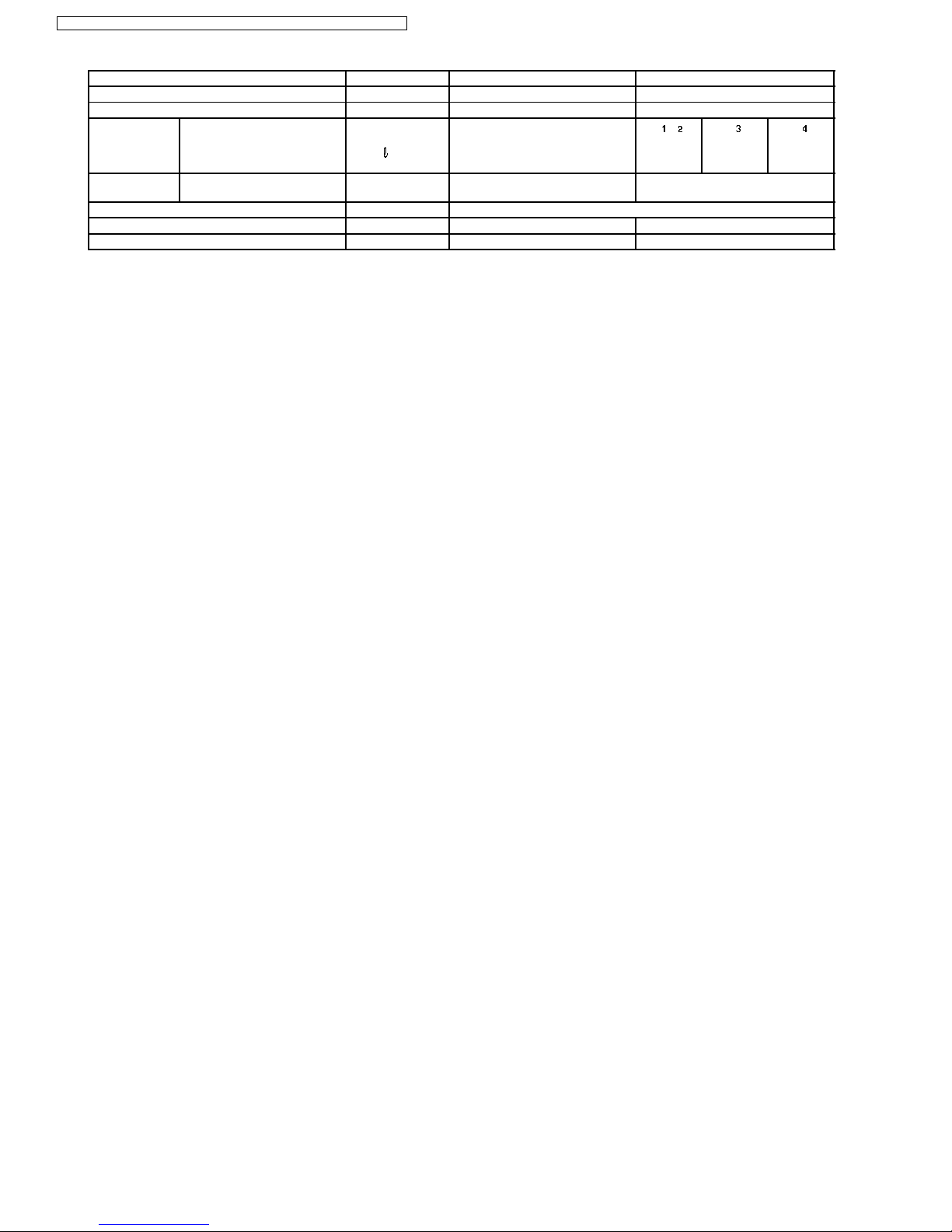
Unit CS-VA70KE CU-VA70KE
Thermostat Electronic Control Protection Device - Overload Protector
Capillary Tube
Length
flow Rate
Inner Diameter
mm
/min
mm
-
-
-
C ,C
970
5.0
1.2
C
310
11.3
1.3
C
610
6.5
1.2
Air Filter Material
style
P.P
Honeycomb
-
Capacity Control Capillary Tube
Compressor Capacitor µF,VAC - 25µF,370VAC
Fan motor Capacitor µF,VAC - 1.2µF,400VAC
·
Specifications are subject to change without notice for further improvement.
8
CS-VA70KE / CU-VA70KE / CS-VA90KE / CU-VA90KE / CS-VA120KE / CU-VA120KE
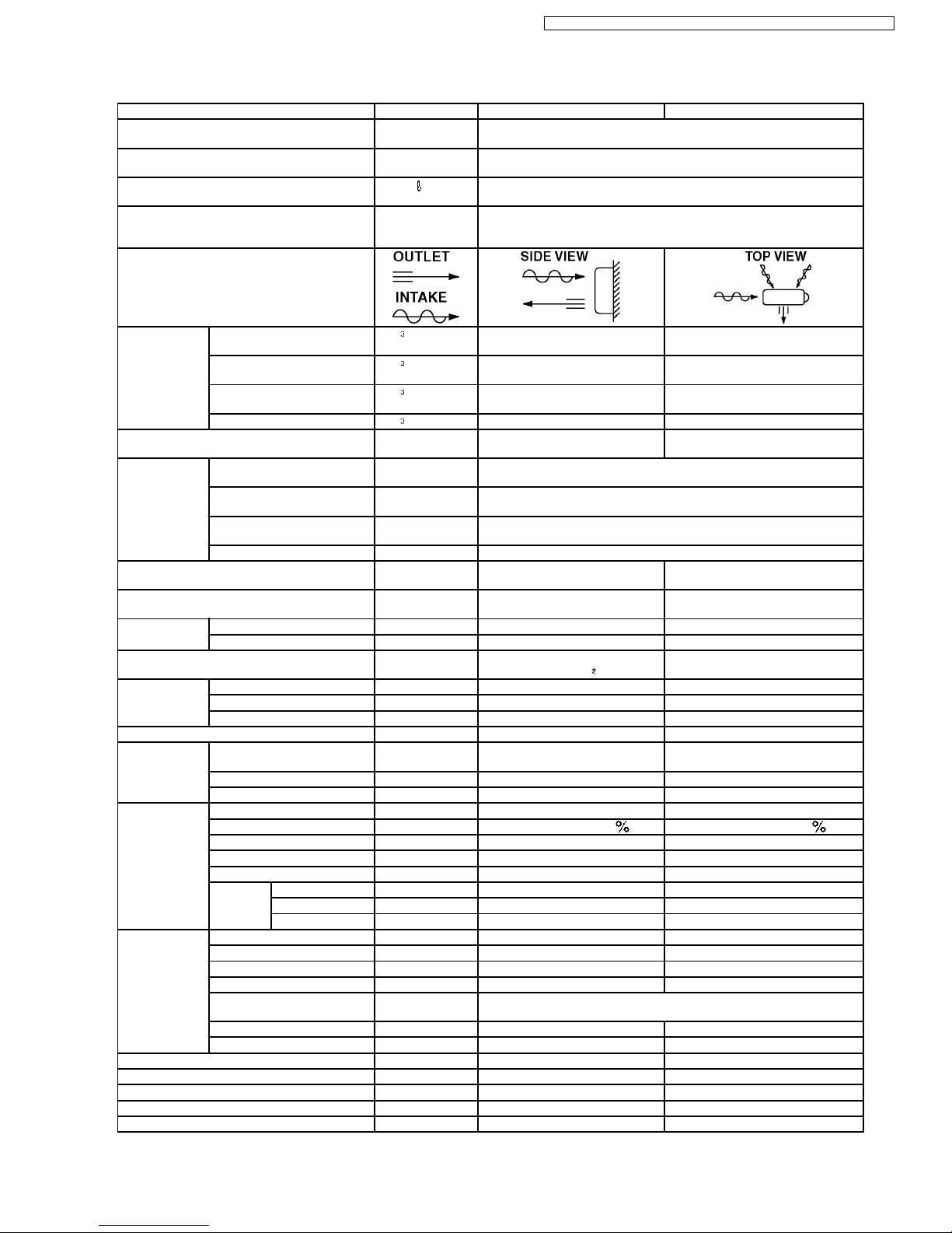
3.2. CS-VA90KE / CU-VA90KE
Unit CS-VA90KE CU-VA90KE
Cooling Capacity kW
Btu/h
2.85
9,700
Heating Capacity kW
Btu/h
3.30
11,300
Moisture Removal /h
Pint/h
1.6
3.4
Power Source Phase
V
Cycle
Single
230
50
Airflow Method
Air Volume Indoor Air(Lo) m / min(cfm) Cooling ; 6.3(220)
Heating ; 6.4(230)
-
Indoor Air(Me) m / min(cfm) Cooling ; 7.4(260)
Heating ; 7.5(260)
-
Indoor Air(Hi) m / min(cfm) Cooling ; 8.5(300)
Heating ; 8.6(300)
-
Outdoor Air m / min(cfm) - 22.4(790)
Noise Level dB(A) Cooling ; High 38,Low 30
heating ; High 38,Low 30
Cooling ; 48
Heating ; 48
Electrical
Data
Input kW Cooling ; 0.94
Heating ; 0.86
Running Current A Cooling ; 4.3
Heating ; 4.0
COP Cooling ; 3.03
Heating ; 3.84
Starting Current A 20
Piping Connection Port
(Flare piping)
inch
inch
G ; Half Union 3/8”
L ; Half Union 1/4”
G ; 3-Way valve 3/8”
L ; 2-Way valve 1/4”
Pipe Size
(Flare piping)
inch
inch
G(gas side) ; 3/8”
L(liquid side) ; 1/4”
G(gas side) ; 3/8”
L(liquid side) ; 1/4”
Drain
Hose
Inner diameter mm 12 Length m 0.7 -
Power Cord length
Number of core-wire
2.1 m
3 (1.0 mm
)
-
-
Dimensions Height inch(mm) 11 - 7/16(290) 18 - 29/32(480)
Width inch(mm) 31 - 15/32(799) 30 - 23/32(780)
Depth inch(mm) 6 - 29/32(175) 9 - 21/32(245)
Net Weight lb(kg) 18(8.0) 71(32.0)
Compressor Type - Rotary(1 cylinder
rolling piston type
Motor Type - Induction(2-poles)
Rated Output W - 750
Air Circularizing Type Cross-flow Fan Propeller Fan
Material AS+Glass Fiber 30 AES+Glass Fiber 12
Motor Type Transiator(4-poles) Induction(6-poles)
Input W - 58.6
rated Output W 20 20
Fan
Speed
Low rpm 980 Medium rpm 1,150 High(heating) rpm 1,310 730
Heat
Exchange
description Evaporator Condenser
Tube material Copper Copper
Fine material Aluminium Aluminium
Fine type Slit Fin Corrugated Fin
Row/Stage (Plate fin configuration, forced draft)
2x12
1x18
FPI 18 19
Size(W x H x L) mm 600 x 252 x 25.4 856 x 457.2 x 22
Refrigerant Control Device - Capillary Tube
refrigeration Oil (c.c) - RB68A(350)
Refrigerant(R410A) g(oz) - 880(31.1)
Thermostat Electronic Control Protection Device - Overload Protector
9
CS-VA70KE / CU-VA70KE / CS-VA90KE / CU-VA90KE / CS-VA120KE / CU-VA120KE
Unit CS-VA90KE CU-VA90KE
Capillary Tube
Length
flow Rate
Inner Diameter
mm
/min
mm
-
-
-
C ,C
970
5.0
1.2
C
750
15.4
1.7
C
590
8.2
1.3
Air Filter Material
style
P.P
Honeycomb
-
Capacity Control Capillary Tube
Compressor Capacitor µF,VAC - 25µF,370VAC
Fan motor Capacitor µF,VAC - 1.2µF,400VAC
·
Specifications are subject to change without notice for further improvement.
10
CS-VA70KE / CU-VA70KE / CS-VA90KE / CU-VA90KE / CS-VA120KE / CU-VA120KE

3.3. CS-VA120KE / CU-VA120KE
Unit CS-VA120KE CU-VA120KE
Cooling Capacity kW
Btu/h
3.55
12,000
Heating Capacity kW
Btu/h
4.00
13,600
Moisture Removal /h
Pint/h
2.0
4.2
Power Source Phase
V
Cycle
Single
230
50
Airflow Method
Air Volume Indoor Air(Lo) m / min(cfm) Cooling ; 7.5(260)
Heating ; 7.8(280)
-
Indoor Air(Me) m / min(cfm) Cooling ; 8.4(300)
Heating ; 8.7(310)
-
Indoor Air(Hi) m / min(cfm) Cooling ; 9.3(330)
Heating ; 9.7(340)
-
Outdoor Air m / min(cfm) - 22.0(780)
Noise Level dB(A) Cooling ; High 42,Low 38
heating ; High 42,Low 38
Cooling ; 49
Heating ; 49
Electrical
Data
Input kW Cooling ; 1.24
Heating ; 1.18
Running Current A Cooling ; 5.6
Heating ; 5.4
COP Cooling ; 2.86
Heating ; 3.39
Starting Current A 25
Piping Connection Port
(Flare piping)
inch
inch
G ; Half Union 1/2”
L ; Half Union 1/4”
G ; 3-Way valve 1/2”
L ; 2-Way valve 1/4”
Pipe Size
(Flare piping)
inch
inch
G(gas side) ; 1/2”
L(liquid side) ; 1/4”
G(gas side) ; 1/2”
L(liquid side) ; 1/4”
Drain
Hose
Inner diameter mm 12 Length m 0.7 -
Power Cord length
Number of core-wire
2.1 m
3 (1.0 mm
)
-
-
Dimensions Height inch(mm) 11 - 7/16(290) 19 - 29/32(505)
Width inch(mm) 31 - 15/32(799) 30 - 23/32(780)
Depth inch(mm) 6 - 29/32(175) 9 - 21/32(245)
Net Weight lb(kg) 18(8.0) 83(38.0)
Compressor Type - Rotary(1 cylinder
rolling piston type
Motor Type - Induction(2-poles)
Rated Output W - 1100
Air Circularizing Type Cross-flow Fan Propeller Fan
Material AS+Glass Fiber 30 AES+Glass Fiber 12
Motor Type Transiator(4-poles) Induction(6-poles)
Input W - 60.2
rated Output W 20 25
Fan
Speed
Low rpm 1200 Medium rpm 1,330 High(heating) rpm 1,500 730
Heat
Exchange
description Evaporator Condenser
Tube material Copper Copper
Fine material Aluminium Aluminium
Fine type Slit Fin Corrugated Fin
Row/Stage (Plate fin configuration, forced draft)
2x12
2x19
FPI 21 16
Size(W x H x L) mm 600 x 252 x 25.4 706 x 457.2 x 44
670 x 457.2 x 44
Refrigerant Control Device - Capillary Tube
refrigeration Oil (c.c) - RB68A(430)
Refrigerant(R410A) g(oz) - 1150(40.6)
Thermostat Electronic Control Protection Device - Overload Protector
11
CS-VA70KE / CU-VA70KE / CS-VA90KE / CU-VA90KE / CS-VA120KE / CU-VA120 KE
Unit CS-VA120KE CU-VA120KE
Capillary Tube
Length
flow Rate
Inner Diameter
mm
/min
mm
-
-
-
C
600
12.2
1.5
C
540
10.4
1.4
Air Filter Material
style
P.P
Honeycomb
-
Capacity Control Capillary Tube
Compressor Capacitor µF,VAC - 30µF,370VAC
Fan motor Capacitor µF,VAC - 1.2µF,400VAC
·
Specifications are subject to change without notice for further improvement.
12
CS-VA70KE / CU-VA70KE / CS-VA90KE / CU-VA90KE / CS-VA120KE / CU-VA120KE
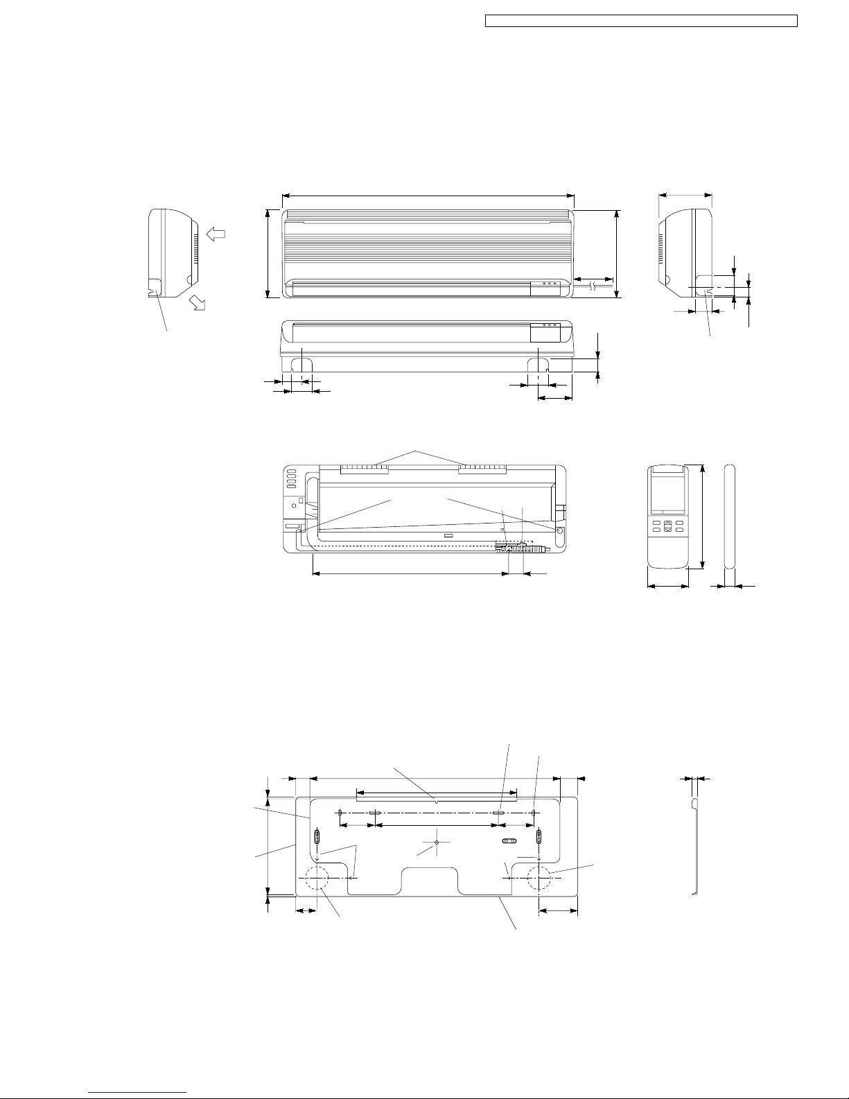
4 Dimensions
4.1. CS-VA70KE / CS-VA90KE / CS-VA120KE (INDOOR UNIT)
Relative position between the indoor unit and the installation plate <Front View>
799
48.5
60
290
<Front View>
175
61
34.5
52
direction
Air intake
Air outlet
direction
Left piping hole
Right piping hole
290
115
55
60
2100
57
142
16
Remote control transmitter
(45)(410)
<Back View>
Installation plate hooks
Drain ports
Gas
side
Liquid
side
(40)
710
(40)
276
7
(60)
(110)
100 100
Slot (2 places)
Slot (2 places)
Centre notch
Indoor unit external
dimensions line
Installation plate
Left piping hole
Arrow
Arrow
Centre
Right piping hole
Installation plate positioning gauge
350
7
457
13.5
13
CS-VA70KE / CU-VA70KE / CS-VA90KE / CU-VA90KE / CS-VA120KE / CU-VA120KE
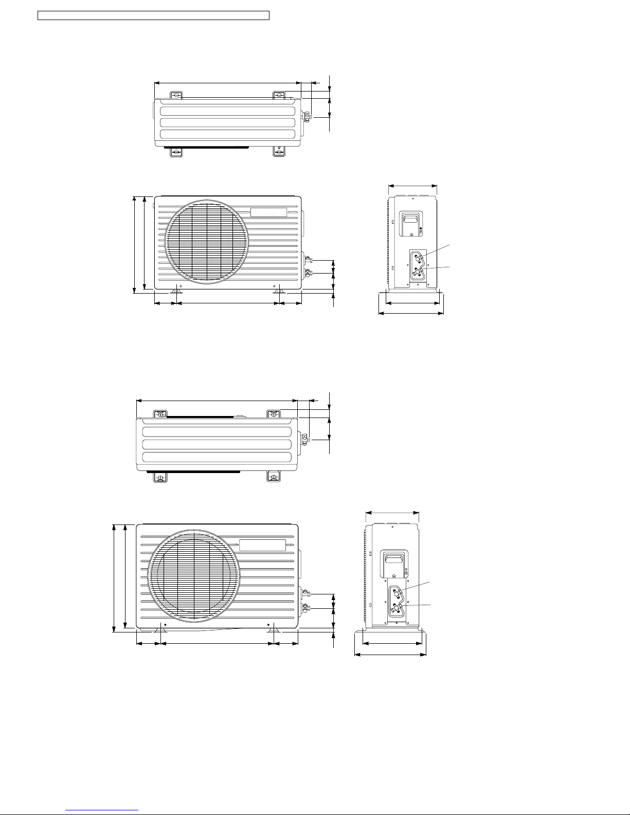
4.2. CU-VA70KE / CU-VA90KE (OUTDOOR UNIT)
67
77
105105 570
467
480
280
312
245
2-way valve
at Liquid side
13
at Gas side
3-way valve
93
27.5
780 57
Panasonic
4.3. CU-VA120KE(OUTDOOR UNIT)
67
93
105105 570
494
505
280
312
245
2-way valve
at Liquid side
11
at Gas side
3-way valve
112
27.5
780 57
14
CS-VA70KE / CU-VA70KE / CS-VA90KE / CU-VA90KE / CS-VA120KE / CU-VA120KE
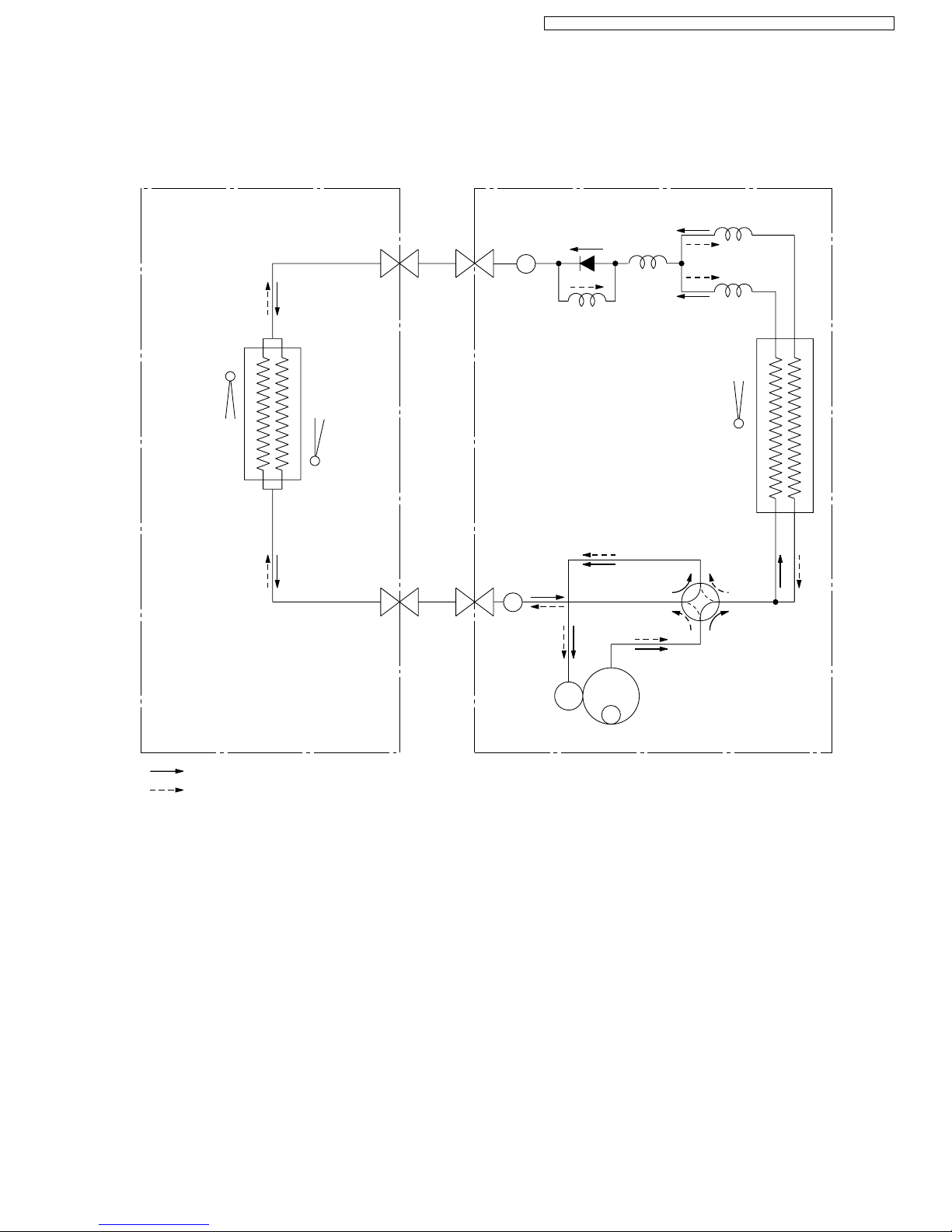
5 Refrigeration Cycle Diagram
5.1. CS-VA70KE / CU-VA70KE, CS-VA90KE / CU-VA90KE
COMP.
4-WAY VALVE
C1
C4
C2
CHECK VALVE
DRYER
PIPE
TEMP.
SENSOR
(T.R.S)
SENSOR
TEMP.
INTAKE
PIPE
TEMP.
SENSOR
INDOOR OUTDOOR
COOLING
HEATING
HEAT EXCHANGER
(EVAPORATOR)
HEAT EXCHANGER
(CONDENSER)
2-WAY
VALVE
VALVE
3-WAY
C3
STRAINER
C1,C2,C3,C4; CAPILLARY TUBE
15
CS-VA70KE / CU-VA70KE / CS-VA90KE / CU-VA90KE / CS-VA120KE / CU-VA120KE
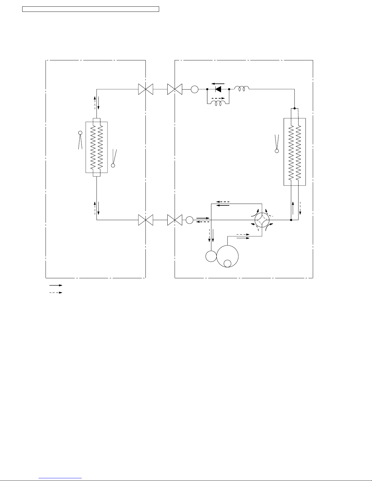
5.2. CS-VA120KE / CU-VA120KE
COMP.
4-WAY VALVE
C2
CHECK VALVE
DRYER
PIPE
TEMP.
SENSOR
(T.R.S)
SENSOR
TEMP.
INTAKE
PIPE
TEMP.
SENSOR
INDOOR OUTDOOR
COOLING
HEATING
HEAT EXCHANGER
(EVAPORATOR)
HEAT EXCHANGER
(CONDENSER)
2-WAY
VALVE
VALVE
3-WAY
C1
STRAINER
C1,C2 ; CAPILLARY TUBE
16
CS-VA70KE / CU-VA70KE / CS-VA90KE / CU-VA90KE / CS-VA120KE / CU-VA120KE
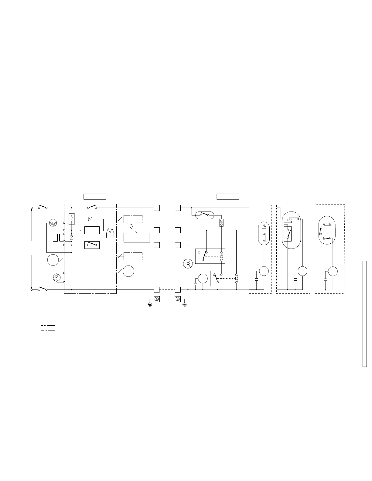
6 Block Diagram
FUSE
ZNR1
ZNR2
3
4
1
TRANSFORMER
FM
CT1
STEPPING
3C
4C
5C
RECEIVER
P.C.B.
INDICATOR
P.C.B.
WIRELESS
REMOTE CONTROL
TRANSMITTER
22
1
4
3
FM
RELAY
B
RELAY A
COMP
COMP
O.L.P.
O.L.P.
FOR
CU-VA90KE
FOR
CU-VA70KE
MAIN
POWER SWITCH
SSR1
RY-HOT
SINGLE
50Hz
AC 230V
PHASE
INDOOR UNIT OUTDOOR UNIT
CS/CU-VA70KE/VA90KE/VA120KE
A-008.DWG
P.C.B.
MOTOR
TRS
4-WAY
VALVE
(3.15A)
3C
THERMAL FUSE
(102°C)
INDOOR
FAN MOTOR
THERMAL FUSE
(99°C)
RY-PWR
CS-VA70KE / CU-VA70KE
CS-VA90KE / CU-VA90KE
CS-VA120KE / CU-VA120KE
"C"
Indicates the electronic control unit.
Indicates the number of core wires. (Example:5C=5 core wires).
**
COMP
O.L.P.
FOR
CU-VA120KE
CS-VA70KE / CU-VA70KE / CS-VA90KE / CU-VA90KE / CS-VA120KE / CU-VA120KE
17
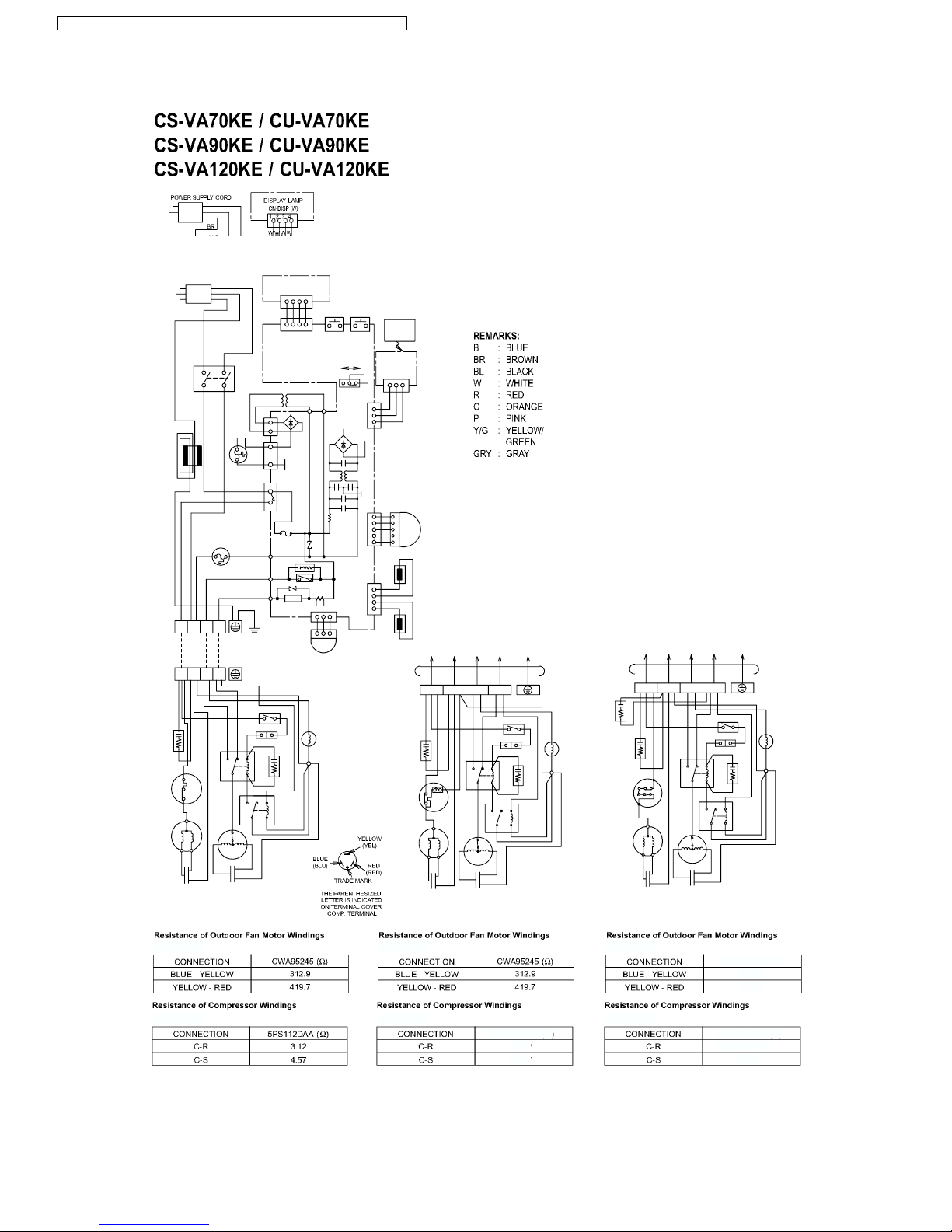
7 Wiring Diagram
POWER SUPPLY CORD
DISPLAY LAMP
Y/G
B
BL
FUSE
(Y2A L250W)
R
R
B
B1
3
2
2
3
1
1
1
2
3
4
2
MOTOR
(FLAP)
3
4
5
1
BR
R
O
Y
P
2
3
4
5
B
B
A
T(BL) T(BL)
R
R
1
3
TRANSFORMER BL
2
MAIN SW.
143
BR
BR
CORE
CN-STM (G)CN-TH (Y)
SENSOR
(PIPE TEMP .)
SENSOR
(INTAKE TEMP.)
THERMAL FUSE
(102°C)
CN FUSE
(B)
CN-T (W)
WIRELESS
REMOTE
CONTROL
ELECTRONIC
CONTROLLER
(RECEIVER)
CN-RCV (W)
1234
4321
WWWW
CN-DISP (W)
CN-DISP (W)
ELECTRONIC
CONTROLLER
PUMP
DOWN SW
(TEST RUN)
REMOTE
CONTROL NO.
AUTO
SW.
1
234
1
234
INDOOR UNIT
TERMINAL
OUTDOOR UNIT
TERMINAL
CAPACITOR CAPACITOR
3
2
1
FAN MOTOR
YELLOW
BROWN
BLACK
BLACK
BLUE
BLACK
GRAY
BLUE
BLUE
COIL
REVERSING VALVE
BLUE
BLUE
RED
BLACK
WHITE
TRS
4
R
B
FM (B)
HD1(R)
NV-HD1
AC(W)
BR
321
Y
W
L
P
AC
(BR)
COMP
(BL)
THERMAL FUSE
(99°C)
BL
W
W
28
76
428
76
BLACK
BLACK
BLACK
YELLOW
GRAY
RED
RED
GRAY
COMPRESSOR
OVER LOAD
PROTECTOR
ELECTROLYTIC
CAPACITOR
MAGNETIC RELAY A
MAGNETIC RELAY B
ELECTROLYTIC
CAPACITOR
Y/G
ZNR1
CR1
CT1
ZNR2
SSR1
CN-MTR (G)
MOTOR
135
CN-RCV(W)
CU-VA70KE
CU-VA70KE
CU-VA90KE
CU-VA90KE
CU-VA120KE
CU-VA70KE
CU-VA90KE
CU-VA120KE
CU-VA120KE
5PS112DAA(Ω) 5KS150DAA(Ω)
3.12
4.57
2.21
3.53
CWA95230(Ω)
312.9
419.5
123
CAPACI TOR
CAPACITOR CAPACITOR CAPACITOR
4
BLUE
RED
COMPRESSOR
COMPRESSOR
TERMINAL
TERMINAL
ELECTROLYTIC
CAPACITOR
ELECTROLYTIC
CAPACITOR
2
1
2
4
6
8
7
F
A
N
M
O
T
O
R
F
A
N
M
O
T
O
R
M
A
G
N
E
T
I
C
R
E
L
A
Y
M
A
G
N
E
T
I
C
R
E
L
A
Y
M
A
G
N
E
T
I
C
R
E
L
A
Y
M
A
G
N
E
T
I
C
R
E
L
A
Y
4
6
872
COI L
REVERSING VAL VE
COI L
REVERSING VAL VE
TO INDOOR UNIT TO INDOOR UNIT
ELECTROL YTIC
CAPA CITO
R
OVER LOA D
PROTECTOR
TRS
WHITE
BLUE
RED
WHITE
YELLOW
YELLOW
BLUE
BLUE
RED
BLACK
BLACK
BLACK
BLACK
BROWN
BLACK
BLACK
GRAY
RED
RED
GRAY
GRAY
WHI TE
WHITE
GRAY
BLUE
B
L
UE
BLACK
BLACK
A
1234
2
4
6
8
7
4
6
872
ELECT ROLYTI C
CAPA CI T OR
OVER L OAD
PROTECTOR
TRS
YELL O W
YELL O W
BLUE
BLUE
R
ED
BLACK
BLACK
BLACK
BLACK
BLACK
BLACK
GRAY
WHITE
GRAY
BLUE
BLUE
B
B
A
4
1
BLACK BL ACK
BLACK
BLACK
18
CS-VA70KE / CU-VA70KE / CS-VA90KE / CU-VA90KE / CS-VA120KE / CU-VA120 KE
8 Operation Details
8.1. COOLING MODE OPERATION
Cooling in operation according to the remote control setting.
8.1.1. Time Delay Safety Control (3 minutes)
· When the compressor is stopped by Power Switch, Remote Control or when there is a power failure, it restarts after 3 minutes
when the Power Switch, Remote Control is turned ON or when the power supply is resumed.
· When the setting temperature is reached during cooling operation, the compressor stops and it will not start for 3 minutes.
8.1.2. 7 Minutes Time Save Control
· The compressor will start automatically if it has stopped for 7 minutes even if the room temperature is below the compressor
ON temperature.
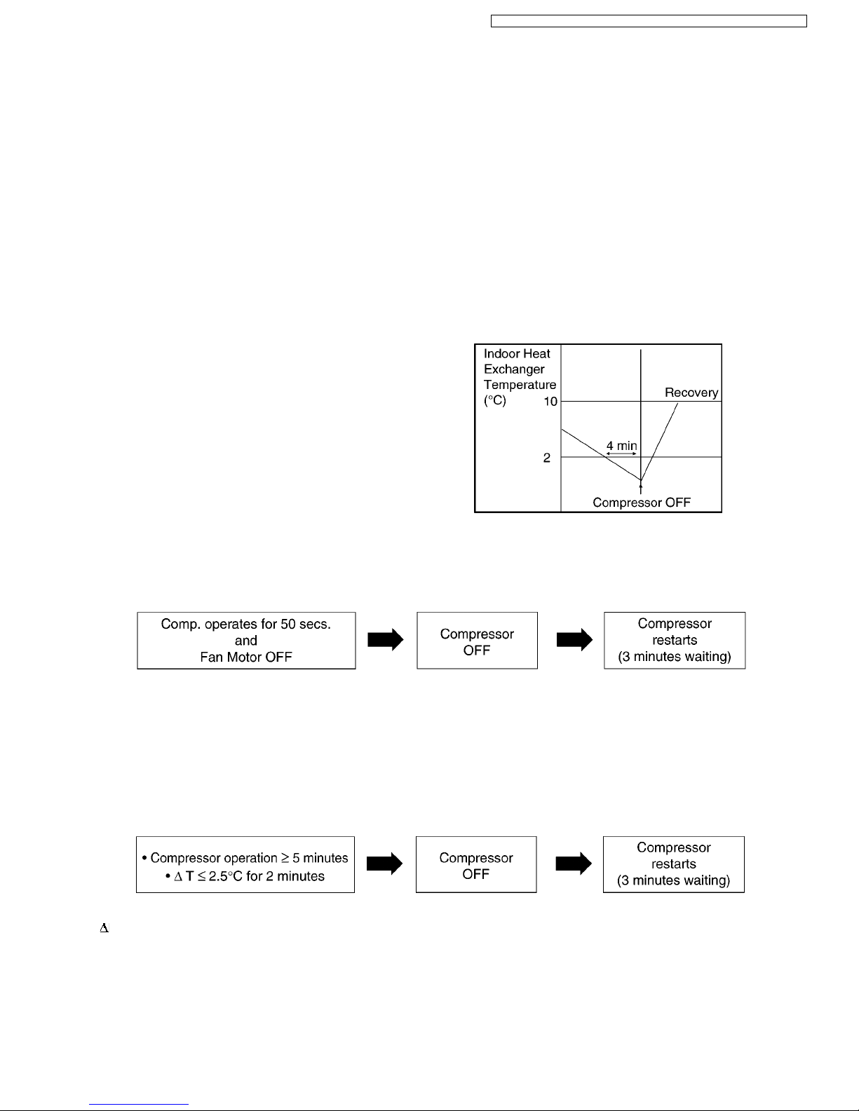
8.1.3. Anti-Freezing Control
·
If the temperature of the indoor heat exchanger falls
continously below 2°C for 4 minutes, the compressor turns off
to protect the indoor heat exchanger from freezing.The fan
speed setting remains the same.
·
Compressor recommences when the indoor heat exchanger
temperature rises to 10 °C (Recovery).
*3 minutes waiting of Time Delay Safety Control is valid for
Cooling Operation.
8.1.4. Compressor Protection Control
· After the compressor operates for 50 seconds but the outdoor fan motor is still OFF, the compressor will stop and restart
automatically.(Time Delay Safety Control is valid).
· If the above phenomenon is repeated 3 times, the compressor will stop.
· The above phenomenon is reset when there is a change to heating mode or stopped by Remote Control Switch.
8.1.5. Compressor Reverse Rotation Protection Control
· If the compressor is operating continually for 5 minutes or longer and the temperature difference between intake air and indoor
heat exchanger is 2.5 °C or less for 2 minutes, the compressor will stop and restart automatically.
(Time Delay Safety Control is valid).
T =Intake air temperature - Indoor heat exchanger temperature
This is to protect the compressor against reverse rotation when there is an instantaneous power failure.
19
CS-VA70KE / CU-VA70KE / CS-VA90KE / CU-VA90KE / CS-VA120KE / CU-VA120KE
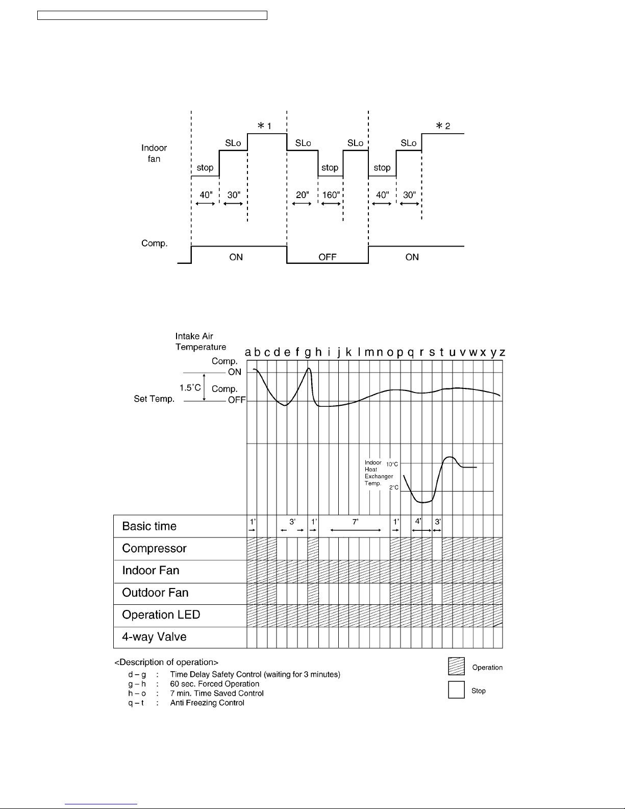
8.1.6. Automatic Fan Speed Mode
When Automatic Fan Speed is selected on the remote control during cooling operation.
· Fan speed rotates in the range of Hi to Me.
· Deodorizing Control.
*1 Fan Speed is Hi until the compressor stops (when the set temperature is reached).
*2 Fan Speed is Me after the compressor restarts.
8.1.7. Cooling Operation Time Diagram
20
CS-VA70KE / CU-VA70KE / CS-VA90KE / CU-VA90KE / CS-VA120KE / CU-VA120KE
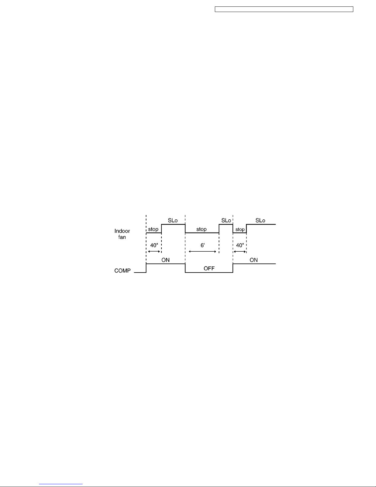
8.2. SOFT DRY MODE OPERATION
· The unit performs cooling operation until the room temperature reaches the setting temperature set on the Remote Contro l, and
then Soft Dry operation will start.
(During Soft Dry operation, the indoor fan operates with SLo speed.)
· Once room temperature reaches below Soft Dry OFF temperature, Indoor Fan, Compressor and Outdoor Fan stop for 6
minutes.
8.2.1. Time Delay Safety Control
· Once the compressor stops, it will not restart for 3 minutes during Cooling operation.
8.2.2. Anti-Freezing Control
· Same as Anti-Freezing Control for Cooling Mode operation.(For Soft Dry operation,6 minutes waiting is valid during compressor
stops.)
8.2.3. Compressor Protection Control
· Same as Compressor Protection Control for Cooling Mode Operation.
8.2.4. Compressor Reverse Rotation Protection
· Same as Compressor Reverse Rotation Protection Control for Cooling Mode Operation.
8.2.5. Automatic Fan Speed Mode
When Automatic Fan Speed is selected on the remote control during Soft Dry Operation.
· Fan speed rotates at SLo.
· Deodorizing Control.
21
CS-VA70KE / CU-VA70KE / CS-VA90KE / CU-VA90KE / CS-VA120KE / CU-VA120KE
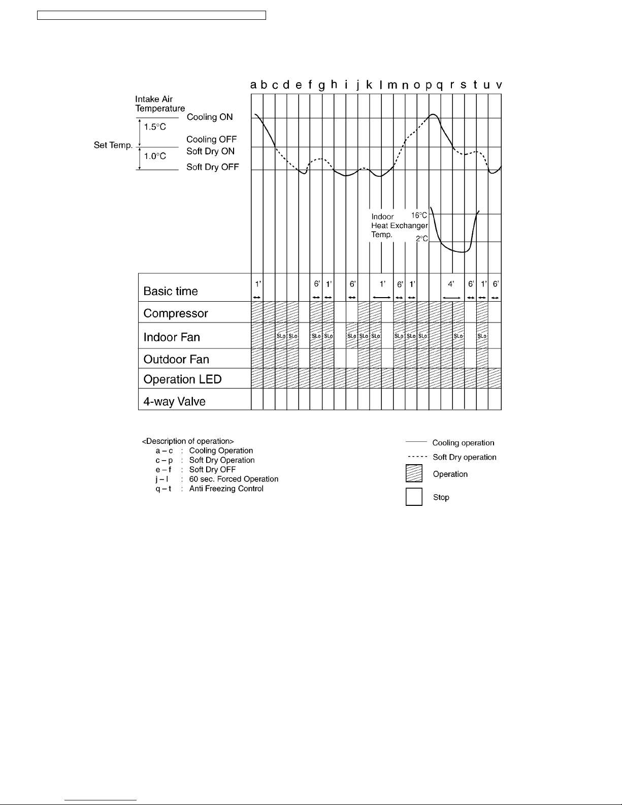
8.2.6. Soft Dry Operation Time Diagram
22
CS-VA70KE / CU-VA70KE / CS-VA90KE / CU-VA90KE / CS-VA120KE / CU-VA120KE
Heating in operation according to the remote control setting.
8.3. HEATING MODE OPERATION
8.3.1. Time Delay Safety Control
· When the compressor is stopped by Power Switch, Remote Control or when there is a power failure, it restarts after 3 minutes
when the Power Switch, Remote Control is turned ON or the power supply is resumed.
· When the setting temperature is reached during heating operation, the compressor stops and it will not restart for 4 minutes.
· Indoor Fan stops for 1 minute 3 minutes after the compressor stopped.Then,it will operate with SLo fan speed.
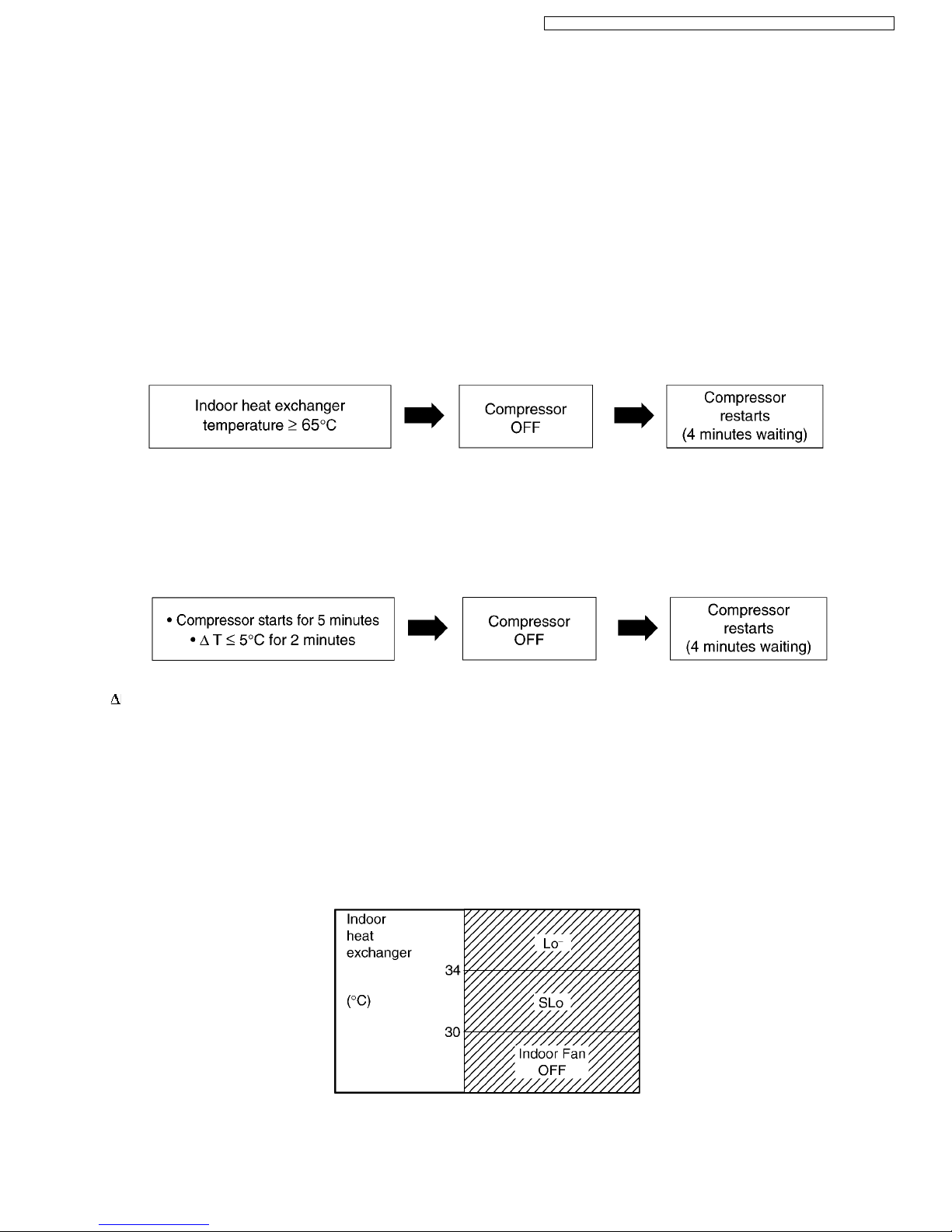
8.3.2. Overload Protection Control
· If the temperature of the indoor heat exchanger rises to 51 °C, Outdoor Fan stops.
The Outdoor Fan restarts when the indoor heat exchanger temperature falls to 49 °C.
· If the indoor heat exchanger becomes 65 °C or more, the compressor will stop and restart automatically.
(Time Delay Safety Control -4 minutes waiting)
8.3.3. Compressor Reverse Rotation Protection Control
· If the compressor is operating continually for 5 minutes or longer and temperature difference between intake air and indoor heat
exchanger is 5 C or less for 2 minutes, the compressor will stop and restart automatically.
(Time Delay Safety Control is valid).
T =Indoor heat exchanger temperature - intake air temperature
This is to protect the compressor against reverse rotation when there is a instantaneous power failure.
8.3.4. 4-way Valve Control
· 4way valve always ON during Heating operation.
· When the unit is switched to "OFF" during Heating operation,4-way valve stays at Heating position for 5 minutes.
8.3.5. Hot Start Control
When Heating operation starts, Indoor Fan will not start until the indoor heat exchanger reaches 30 °C as shown in the diagram
below.
Hot Start is completed when indoor heat exchanger reaches 41 °C.
23
CS-VA70KE / CU-VA70KE / CS-VA90KE / CU-VA90KE / CS-VA120KE / CU-VA120KE
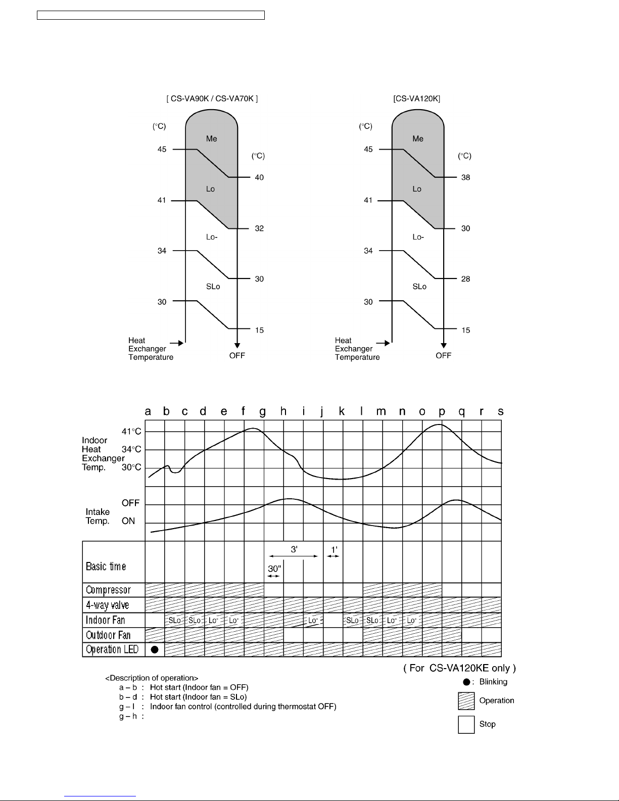
8.3.6. Automatic Fan Speed Mode
When Automatic Fan Speed is selected on the remote control during heating operation.
· Fan speed rotates in the range of Me → SLo according to the heat exchanger temperature.
8.3.7. Heating Operating Time Diagram
24
CS-VA70KE / CU-VA70KE / CS-VA90KE / CU-VA90KE / CS-VA120KE / CU-VA120KE
 Loading...