

Page 1
Order No. MAC0412062C2
Air Conditioner
CS-V7DKE CU-V7DKE
CS-V9DKE CU-V9DKE
CS-V12DKE CU-V12DKE
CONTENTS
Page Page
1 Features 3
2 Functions
2.1. Remote Control
2.2. Indoor Unit
2.3. Outdoor Unit
3 Product Specifications
3.1. CS-V7DKE CU-V7DKE
4
4
5
6
7
7
3.2. CS-V9DKE CU-V9DKE 9
3.3. CS-V12DKE CU-V12DKE
4 Dimensions
4.1. Indoor Unit & Remote Control
4.2. Outdoor Unit
5 Refrigeration Cycle Diagram
6 Block Diagram
© 2004 Panasonic HA Air-Conditioning (M) Sdn Bhd
(11969-T). All rights reserved. Unauthorized copying
and distribution is a violation of law.
11
13
13
14
15
16
Page 2
CS-V7DKE CU-V7DKE / CS-V9DKE CU-V9DKE / CS-V12DKE CU-V12DK E
7 Wiring Diagram 17
8 Operation Details
8.1. Cooling Operation
8.2. Soft Dry Operation
8.3. Automatic Operation
8.4. Operation Control
8.5. Indoor Fan Speed Control
8.6. Outdoor Fan Speed Control
8.7. Vertical Airflow Direction Control
8.8. Horizontal Airflow Direction Control
8.9. Powerful Operation
8.10. Quiet Operation
8.11. Ionizer Operation
8.12. Timer Control
8.13. Random Auto Restart Control
8.14. Remote Control Signal Receiving Sound
9 Operating Instructions
10 Installation Instructions
10.1. Safety Precautions
10.2. Indoor Unit
10.3. Outdoor Unit
11 Installation And Servicing Air Conditioner Using R410A
11.1. Outline
11.2. Tools For Installing/Servicing Refrigerant Piping
11.3. Refrigerant Piping Work
11.4. Installation, Transferring, Servicing
12 Servicing Information
12.1. Distinction Of Lead Free (PbF) Printed Circuit Board
12.2. Indoor Electronic Controllers Removal Procedures
18
18
19
20
20
22
24
24
25
25
25
27
28
28
28
29
35
35
38
42
45
45
46
50
52
56
56
56
12.3. Indoor Fan Motor And Cross Flow Fan Removal
Procedures
12.4. Remote Control Reset
12.5. Auto OFF/ON Button
13 Troubleshooting Guide
13.1. Refrigeration Cycle System
13.2. Relationship Between The Condition Of The Air
Conditioner And Pressure And Electric Current
13.3. Diagnosis Methods Of A Malfunction Of A Compressor
14 Technical Data
14.1. Thermostat Characteristics
14.2. Sensible Capacity Chart
14.3. Operation Characteristics
15 Exploded View (Indoor Unit)
15.1. CS-V7DKE CS-V9DKE CS-V12DKE
16 Replacement Parts List (Indoor Unit)
16.1. CS-V7DKE CS-V9DKE CS-V12DKE
17 Exploded View (Outdoor Unit)
17.1. CU-V7DKE
17.2. CU-V9DKE CU-V12DKE
18 Replacement Parts List (Outdoor Unit)
18.1. CU-V7DKE
18.2. CU-V9DKE CU-V12DKE
19 Electronic Circuit Diagram
19.1. Indoor Unit & Outdoor Unit
19.2. Remote Control
19.3. Print Pattern Indoor Unit Printed Circuit Board
19.4. Print Pattern Indicator & Receiver Printed Circuit Board
57
58
59
60
60
61
61
62
62
62
63
65
65
66
66
67
67
68
69
69
70
71
71
77
78
80
2
Page 3
1 Features
CS-V7DKE CU-V7DKE / CS-V9DKE CU-V9DKE / CS-V12DKE CU-V12DK E
• High efficien cy.
• Compact design.
• Wider range of horizontal discharge air.
• Air Filter with function to reduce dust and smoke.
• Long installation piping up to 15 meter (CS/CU-V12DKE),
10 meter (CS/CU-V7DKE & CS/CU-V9DKE).
• Supersonic Air Purifying System with Super Alleru-Buster.
− Inactive various harmful airbone elements including
allergens, viruses and bacteria.
− Generated supersonic waves enhance the ability to
collect dust and dirt in the air.
Quality Improvement
•
− Random auto restart after power failure for safety restart
operation.
− Gas leakage detection.
− Prevent Compressor reverse cycle.
− OLP to protect Compressor.
− Noise prevention during soft dry operation.
− Blue coated Condenser for high resistance to corrosion.
− Anti-dew formation control (Cooling & Soft Dry).
Operation Improvement
•
− Quiet mode to provide quiet operation.
− Powerful mode to reach the desired room temperature
quickly.
− Ionizer control for generating negative ion in discharge
air.
− 24-hour timer setting.
Serviceability Improvement
•
− Removable and washable Front Panel.
Environmental Friendly
•
− R410A, which does not contain chlorine, is used as its
refrigerant, so there is no danger of damage to the
ozone layer in Stratosphere.
3
Page 4
CS-V7DKE CU-V7DKE / CS-V9DKE CU-V9DKE / CS-V12DKE CU-V12DK E
2 Functions
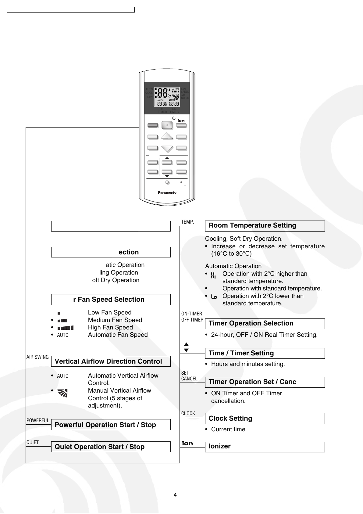
2.1. Remote Control
OFF / ON I
MODE
Operation Start / Stop
Operation Mode Selection
AUTO
COOL
DRY
OFF
TIMERONTIMER
OFF/ON
MODE
POWERFUL
QUIET
TIMER
ON
123
OFF
FAN SPEED
TEMP
AIR SWING
CANCEL
CANCEL
CLOCK RESET
FAN
SPEED
AIR
SWING
SET
TEMP.
Room Temperature Setting
Cooling, Soft Dry Operation.
• Increase or decrease set temperature
(16°C to 30°C)
FAN SPEED
AIR SWING
POWERFUL
• AUTO Automatic Operation
COOL Cooling Operation
•
• DRY Soft Dry Operation
Indoor Fan Speed Selection
• Low Fan Speed
•
•
AUTO Automatic Fan Speed
•
Medium Fan Speed
High Fan Speed
Vertical Airflow Direction Control
• AUTO Automatic Vertical Airflow
Control.
• Manual Vertical Airflow
Control (5 stages of
adjustment).
Powerful Operation Start / Stop
ON-TIMER
OFF-TIMER
▲
▼
SET
CANCEL
CLOCK
Automatic Operation
Operation with 2°C higher than
•
standard temperature.
• Operation with standard temperature.
Operation with 2°C lower than
•
standard temperature.
Timer Operation Selection
• 24-hour, OFF / ON Real Timer Setting.
Time / Timer Setting
• Hours and minutes setting.
Timer Operation Set / Cancel
• ON Timer and OFF Timer setting and
cancellation.
Clock Setting
• Current time setting.
QUIET
Quiet Operation Start / Stop
Ionizer Operation Start / Stop
4
Page 5
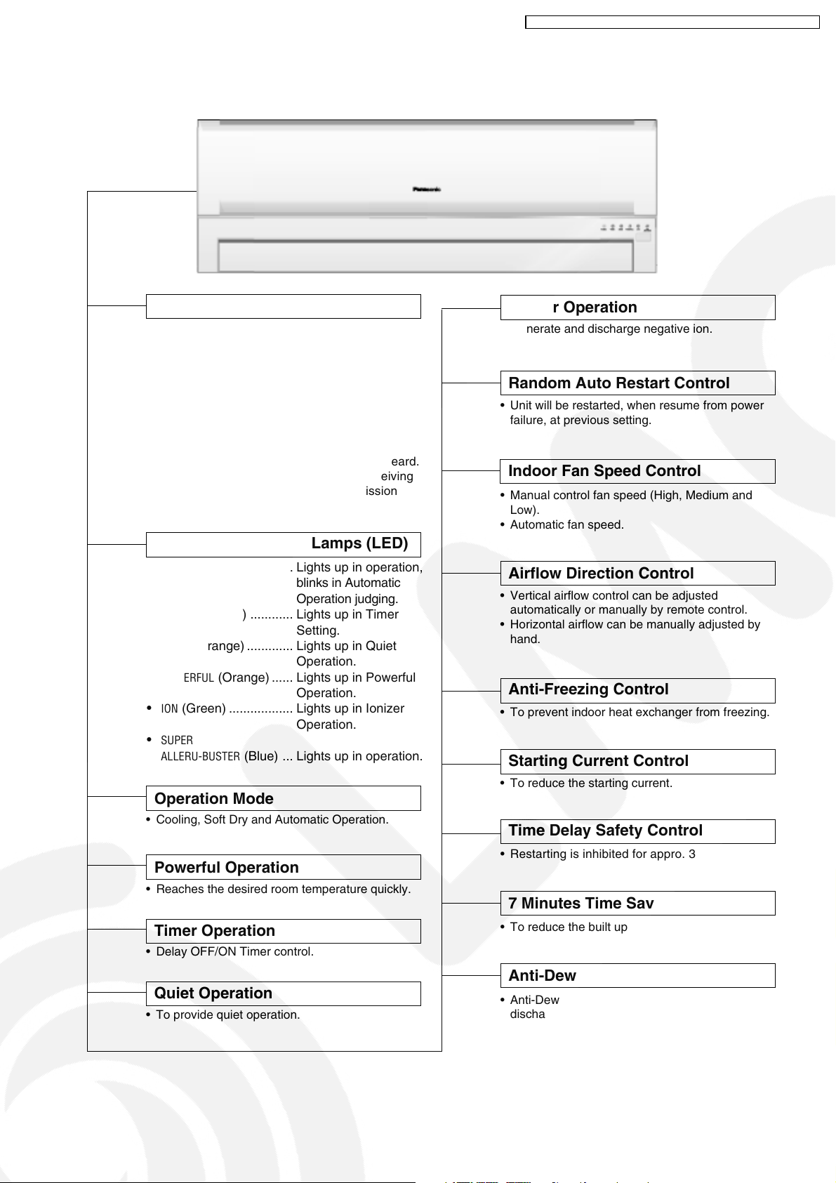
2.2. Indoor Unit
AUTO
OFF / ON
Automatic Operation Button
• Press for < 5 second to operate Automatic
operation mode. Used when the remote control
cannot be used.
• Press for ≥ 5 second to operate Cooling
operation mode and compressor force to on
(“beep” sound will heard). Used when test
running or servicing.
• Within 20 second of Cooling operation, press
continuously for 5 second to enter various
setting mode. “beep, beep” sound will be heard.
(Used to toggle remote control signal receiving
sound or select remote control transmission
code).
Operation Indication Lamps (LED)
•
POWER
(Green) ............. Lights up in operation,
•
TIMER
(Orange) ............ Lights up in Timer
•
QUIET
(Orange) ............. Lights up in Quiet
•
POWERFUL
•
ION
•
SUPER
ALLERU-BUSTER
(Orange) ...... Lights up in Powerful
(Green) .................. Lights up in Ionizer
Operation Mode
• Cooling, Soft Dry and Automatic Operation.
Powerful Operation
• Reaches the desired room temperature quickly.
Timer Operation
• Delay OFF/ON Timer control.
blinks in Automatic
Operation judging.
Setting.
Operation.
Operation.
Operation.
(Blue) ... Lights up in operation.
CS-V7DKE CU-V7DKE / CS-V9DKE CU-V9DKE / CS-V12DKE CU-V12DK E
Ionizer Operation
• Generate and discharge negative ion.
Random Auto Restart Control
• Unit will be restarted, when resume from power
failure, at previous setting.
Indoor Fan Speed Control
• Manual control fan speed (High, Medium and
Low).
• Automatic fan speed.
Airflow Direction Control
• Vertical airflow control can be adjusted
automatically or manually by remote control.
• Horizontal airflow can be manually adjusted by
hand.
Anti-Freezing Control
• To prevent indoor heat exchanger from freezing.
Starting Current Control
• To reduce the starting current.
Time Delay Safety Control
• Restarting is inhibited for appro. 3 minutes.
7 Minutes Time Save Control
• To reduce the built up humidity inside the room.
Quiet Operation
• To provide quiet operation.
Anti-Dew Formation Control
• Anti-Dew Formation Control for indoor unit
discharge area.
5
Page 6
CS-V7DKE CU-V7DKE / CS-V9DKE CU-V9DKE / CS-V12DKE CU-V12DK E
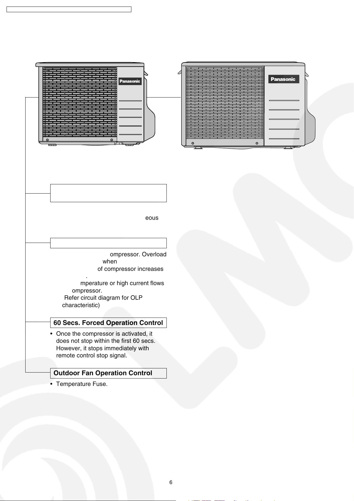
2.3. Outdoor Unit
Compressor Reverse Rotation
Protection Control
• To protect compressor from reverse
rotation when there is a instantaneous
power failure.
Overload Protector
• OLP to protect the compressor. Overload
Protector will trip when
– Temperature of compressor increases
to 120°C.
– High temperature or high current flows
to compressor.
(Refer circuit diagram for OLP
characteristic)
60 Secs. Forced Operation Control
• Once the compressor is activated, it
does not stop within the first 60 secs.
However, it stops immediately with
remote control stop signal.
Outdoor Fan Operation Control
• Temperature Fuse.
6
Page 7
CS-V7DKE CU-V7DKE / CS-V9DKE CU-V9DKE / CS-V12DKE CU-V12DK E
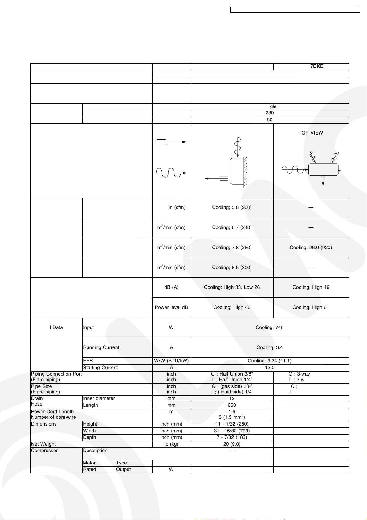
3 Product Specifications
3.1. CS-V7DKE CU-V7DKE
Unit CS-V7DKE CU-V7DKE
Cooling Capacity kW (kcal/h) 2.40 (2,060)
BTU/h 8,180
Moisture Removal l/h (Pint/h) 1.5 (3.2)
Phase ø Single
Power Source Voltage V 230
Cycle Hz 50
Airflow Method OUTLET
INTAKE
Air Volume Lo m3/min (cfm) Cooling; 5.8 (200) —
Me m3/min (cfm) Cooling; 6.7 (240) —
Hi m3/min (cfm) Cooling; 7.8 (280) Cooling; 26.0 (920)
SHi m3/min (cfm) Cooling; 8.5 (300) —
Noise Level dB (A) Cooling; High 33, Low 26 Cooling; High 46
Power level dB Cooling; High 46 Cooling; High 61
SIDE VIEW TOP VIEW
Electrical Data Input W Cooling; 740
Running Current A Cooling; 3.4
EER W/W (BTU/hW) Cooling; 3.24 (11.1)
Starting Current A 12.0
Piping Connection Port
(Flare piping)
Pipe Size
(Flare piping)
Drain
Hose
Power Cord Length
Number of core-wire
Dimensions Height inch (mm) 11 - 1/32 (280) 20 - 3/32 (510)
Net Weight lb (kg) 20 (9.0) 55 (25)
Compressor Description — Rotary (1 cylinder)
Inner diameter mm 12 —
Length mm 650 —
Width inch (mm) 31 - 15/32 (799) 25 - 19/32 (650)
Depth inch (mm) 7 - 7/32 (183) 9 - 1/16 (230)
Motor Type — Induction (2-poles)
Rated Output W — 600
inch
inch
inch
inch
m 1.9
G ; Half Union 3/8”
L ; Half Union 1/4”
G ; (gas side) 3/8”
L ; (liquid side) 1/4”
3 (1.5 mm
G ; 3-way valve 3/8”
L ; 2-way valve 1/4”
G ; (gas side) 3/8”
L ; (liquid side) 1/4”
2
)
—
—
rolling piston type
7
Page 8
CS-V7DKE CU-V7DKE / CS-V9DKE CU-V9DKE / CS-V12DKE CU-V12DK E
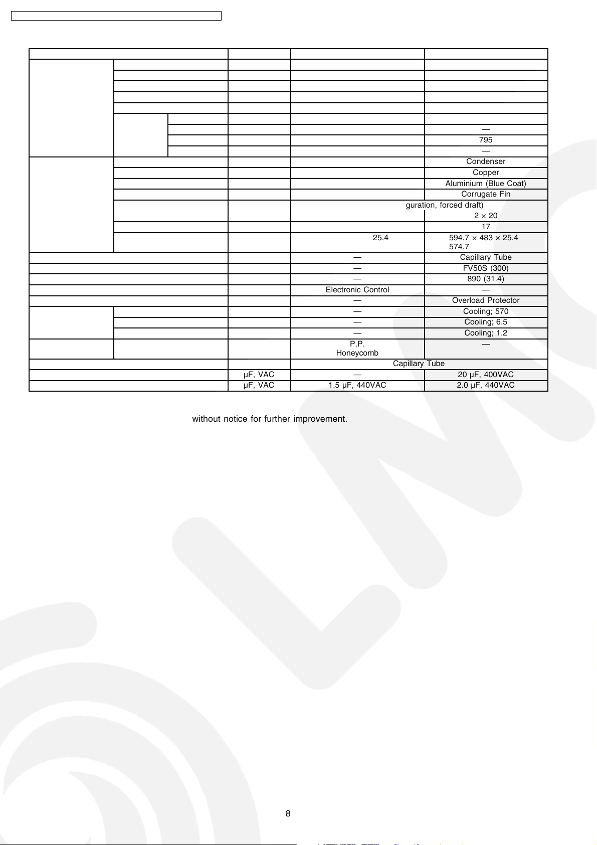
Unit CS-V7DKE CU-V7DKE
Air Circulation Description Cross-flow Fan Propeller Fan
Material ASG20k1 PP Resin
Motor Type Induction (4-poles) Induction (6-poles)
Input W 47 63
Rated Output W 15 30
Fan Speed Low rpm Cooling; 780 —
Medium rpm Cooling; 900 —
High rpm Cooling; 1,050 795
SuperHigh rpm Cooling; 1,140 —
Heat Exchanger Description Evaporator Condenser
Tube material Copper Copper
Fin material Aluminium (Pre Coat) Aluminium (Blue Coat)
Fin Type Slit Fin Corrugate Fin
Row / Stage (Plate fin configuration, forced draft)
2×15 2×20
FPI 21 17
Size (W × H × L) mm 610 × 315 × 25.4 594.7
Refrigerant Control Device — Capillary Tube
Refrigeration Oil (cm3) — FV50S (300)
Refrigerant (R-410A) g (oz) — 890 (31.4)
Thermostat Electronic Control —
Protection Device — Overload Protector
Capillary Tube Length mm — Cooling; 570
Flow Rate l/min — Cooling; 6.5
Inner Diameter mm — Cooling; 1.2
Air Filter Material
Style
Capacity Control Capillary Tube
Compressor Capacitor µF, VAC — 20 µF, 400VAC
Fan Motor Capacitor µF, VAC 1.5 µF, 440VAC 2.0 µF, 440VAC
P.P.
Honeycomb
× 483 × 25.4
574.7
—
•
Specifications are subject to change without notice for further improvement.
8
Page 9
CS-V7DKE CU-V7DKE / CS-V9DKE CU-V9DKE / CS-V12DKE CU-V12DK E
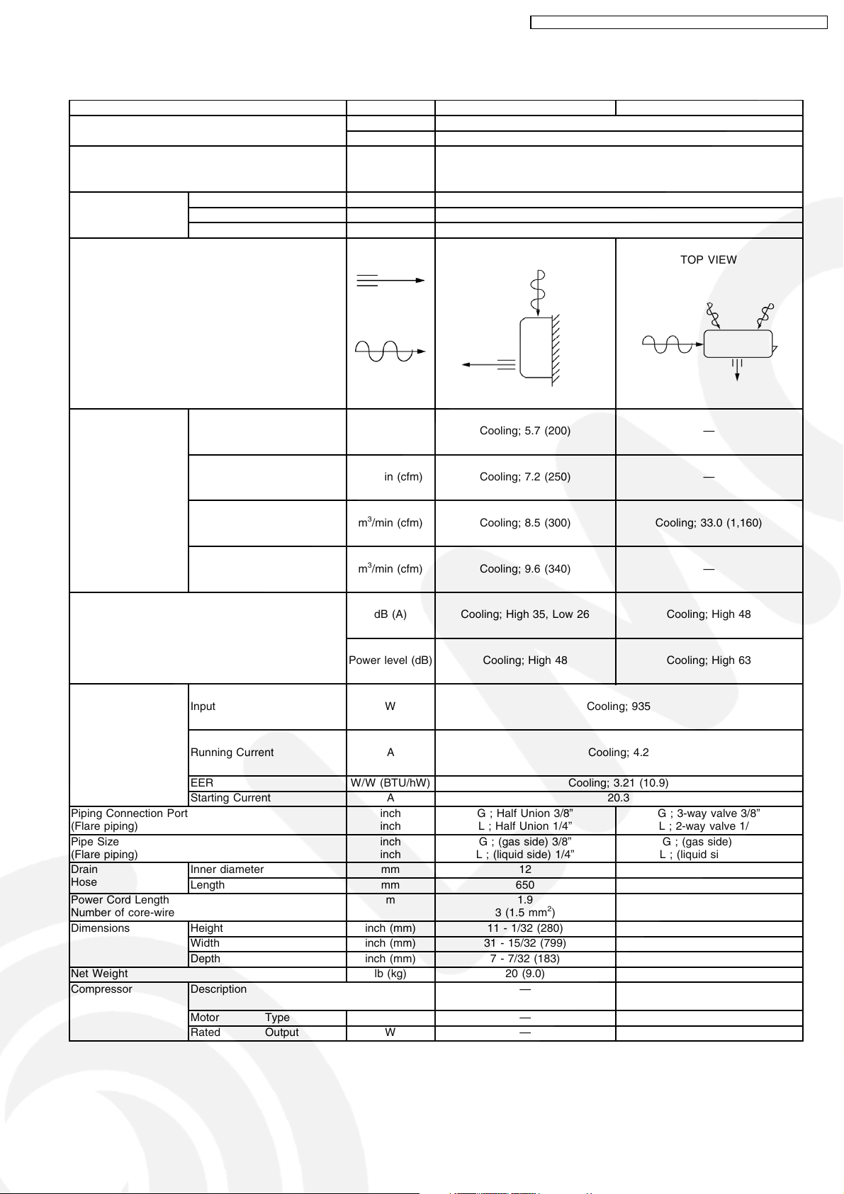
3.2. CS-V9DKE CU-V9DKE
Unit CS-V9DKE CU-V9DKE
Cooling Capacity kW (kcal/h) 3.00 (2,580)
BTU/h 10,230
Moisture Removal l/h (Pint/h) 1.7 (3.6)
Phase ø Single
Power Source Voltage V 230
Cycle Hz 50
Airflow Method OUTLET
INTAKE
Air Volume Lo m3/min (cfm) Cooling; 5.7 (200) —
Me m3/min (cfm) Cooling; 7.2 (250) —
Hi m3/min (cfm) Cooling; 8.5 (300) Cooling; 33.0 (1,160)
SHi m3/min (cfm) Cooling; 9.6 (340) —
Noise Level dB (A) Cooling; High 35, Low 26 Cooling; High 48
Power level (dB) Cooling; High 48 Cooling; High 63
SIDE VIEW TOP VIEW
Electrical Data Input W Cooling; 935
Running Current A Cooling; 4.2
EER W/W (BTU/hW) Cooling; 3.21 (10.9)
Starting Current A 20.3
Piping Connection Port
(Flare piping)
Pipe Size
(Flare piping)
Drain
Hose
Power Cord Length
Number of core-wire
Dimensions Height inch (mm) 11 - 1/32 (280) 21 - 1/4 (540)
Net Weight lb (kg) 20 (9.0) 68 (31)
Compressor Description — Rotary (1 cylinder)
Inner diameter mm 12 —
Length mm 650 —
Width inch (mm) 31 - 15/32 (799) 30 - 23/32 (780)
Depth inch (mm) 7 - 7/32 (183) 11 - 3/8 (289)
Motor Type — Induction (2-poles)
Rated Output W — 750
inch
inch
inch
inch
m 1.9
G ; Half Union 3/8”
L ; Half Union 1/4”
G ; (gas side) 3/8”
L ; (liquid side) 1/4”
3 (1.5 mm
G ; 3-way valve 3/8”
L ; 2-way valve 1/4”
G ; (gas side) 3/8”
L ; (liquid side) 1/4”
2
)
—
—
rolling piston type
9
Page 10
CS-V7DKE CU-V7DKE / CS-V9DKE CU-V9DKE / CS-V12DKE CU-V12DK E
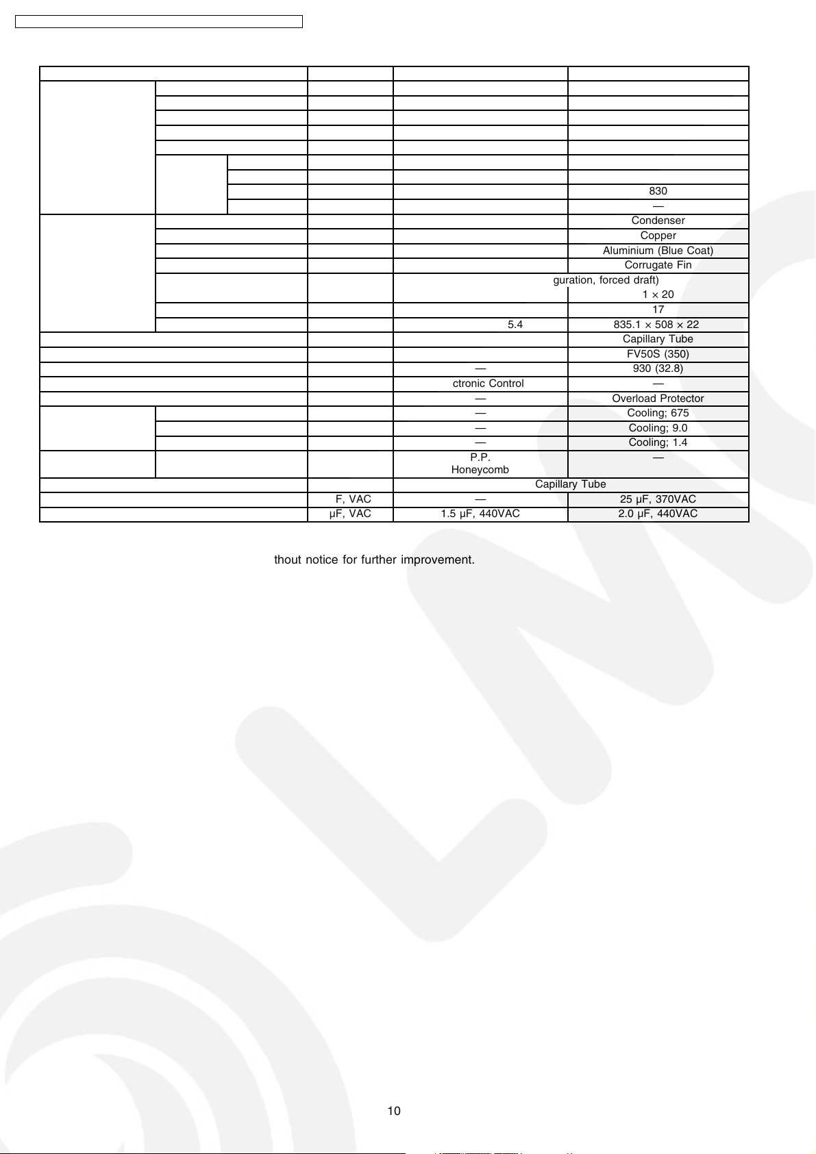
Unit CS-V9DKE CU-V9DKE
Air Circulation Description Cross-flow Fan Propeller Fan
Material ASG20k1 PP Resin
Motor Type Induction (4-poles) Induction (6-poles)
Input W 47 69
Rated Output W 15 30
Fan Speed Low rpm Cooling; 780 —
Medium rpm Cooling; 980 —
High rpm Cooling; 1,160 830
SuperHigh rpm Cooling; 1,310 —
Heat Exchanger Description Evaporator Condenser
Tube material Copper Copper
Fin material Aluminium (Pre Coat) Aluminium (Blue Coat)
Fin Type Slit Fin Corrugate Fin
Row / Stage (Plate fin configuration, forced draft)
2 × 15 1 × 20
FPI 21 17
Size (W × H × L) mm 610 × 315 × 25.4 835.1 × 508 × 22
Refrigerant Control Device — Capillary Tube
Refrigeration Oil (cm3) — FV50S (350)
Refrigerant (R-410A) g (oz) — 930 (32.8)
Thermostat Electronic Control —
Protection Device — Overload Protector
Capillary Tube Length mm — Cooling; 675
Flow Rate l/min — Cooling; 9.0
Inner Diameter mm — Cooling; 1.4
Air Filter Material
Style
Capacity Control Capillary Tube
Compressor Capacitor µF, VAC — 25 µF, 370VAC
Fan Motor Capacitor µF, VAC 1.5 µF, 440VAC 2.0 µF, 440VAC
P.P.
Honeycomb
—
•
Specifications are subject to change without notice for further improvement.
10
Page 11
CS-V7DKE CU-V7DKE / CS-V9DKE CU-V9DKE / CS-V12DKE CU-V12DK E
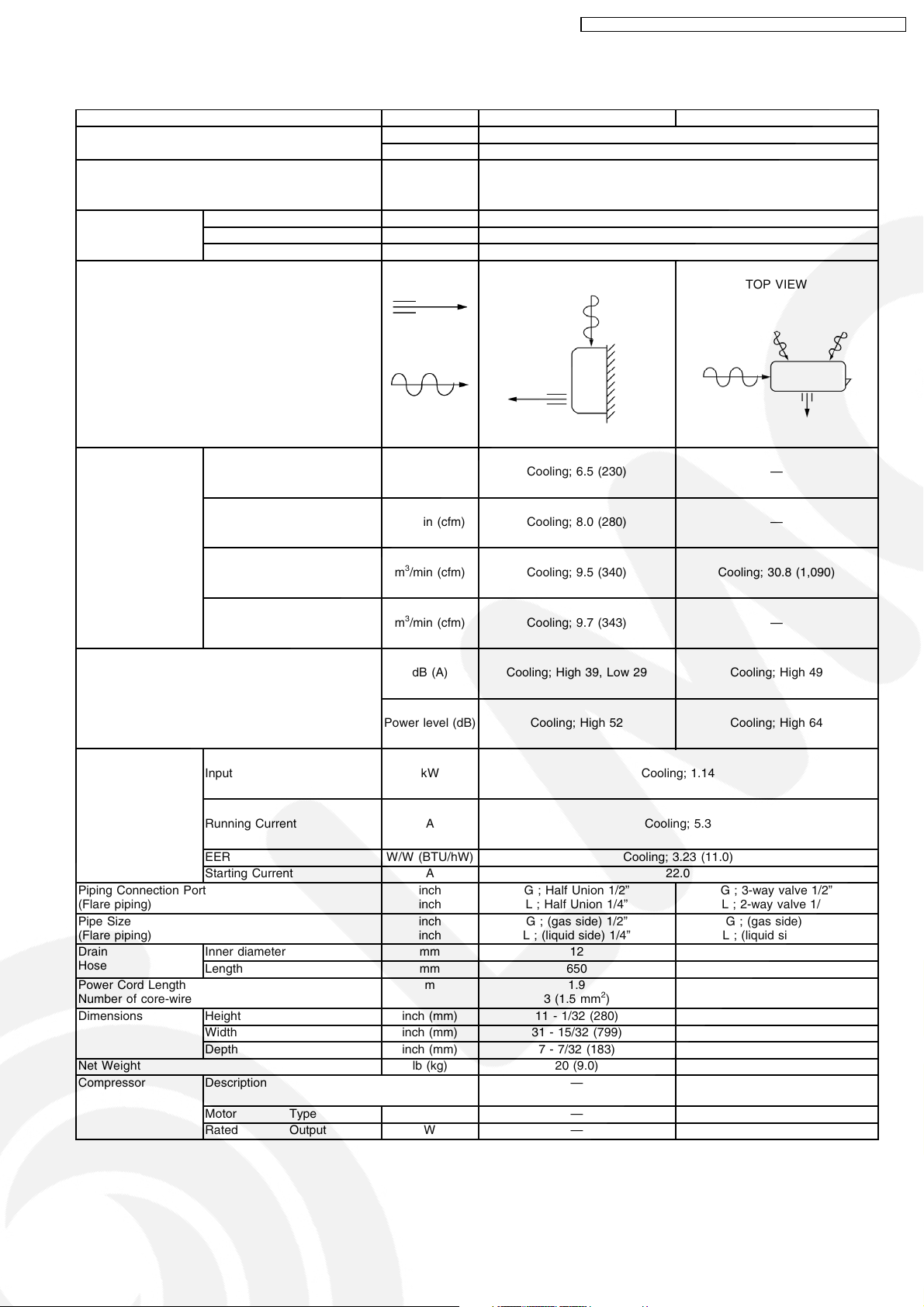
3.3. CS-V12DKE CU-V12DKE
Unit CS-V12DKE CU-V12DKE
Cooling Capacity kW (kcal/h) 3.68 (3,160)
BTU/h 12,550
Moisture Removal l/h (Pint/h) 2.1 (4.4)
Phase ø Single
Power Source Voltage V 230
Cycle Hz 50
Airflow Method OUTLET
INTAKE
Air Volume Lo m3/min (cfm) Cooling; 6.5 (230) —
Me m3/min (cfm) Cooling; 8.0 (280) —
Hi m3/min (cfm) Cooling; 9.5 (340) Cooling; 30.8 (1,090)
SHi m3/min (cfm) Cooling; 9.7 (343) —
Noise Level dB (A) Cooling; High 39, Low 29 Cooling; High 49
Power level (dB) Cooling; High 52 Cooling; High 64
SIDE VIEW TOP VIEW
Electrical Data Input kW Cooling; 1.14
Running Current A Cooling; 5.3
EER W/W (BTU/hW) Cooling; 3.23 (11.0)
Starting Current A 22.0
Piping Connection Port
(Flare piping)
Pipe Size
(Flare piping)
Drain
Hose
Power Cord Length
Number of core-wire
Dimensions Height inch (mm) 11 - 1/32 (280) 21 - 1/4 (540)
Net Weight lb (kg) 20 (9.0) 73 (33)
Compressor Description — Rotary (1 cylinder)
Inner diameter mm 12 —
Length mm 650 —
Width inch (mm) 31 - 15/32 (799) 30 - 23/32 (780)
Depth inch (mm) 7 - 7/32 (183) 11 - 3/8 (289)
Motor Type — Induction (2-poles)
Rated Output W — 900
inch
inch
inch
inch
m 1.9
G ; Half Union 1/2”
L ; Half Union 1/4”
G ; (gas side) 1/2”
L ; (liquid side) 1/4”
3 (1.5 mm
G ; 3-way valve 1/2”
L ; 2-way valve 1/4”
G ; (gas side) 1/2”
L ; (liquid side) 1/4”
2
)
—
—
rolling piston type
11
Page 12
CS-V7DKE CU-V7DKE / CS-V9DKE CU-V9DKE / CS-V12DKE CU-V12DK E
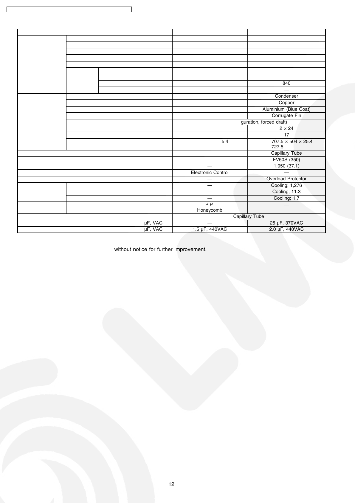
Unit CS-V12DKE CU-V12DKE
Air Circulation Description Cross-flow Fan Propeller Fan
Material ASG20k1 PP Resin
Motor Type Induction (4-poles) Induction (6-poles)
Input W 47 74
Rated Output W 15 35
Fan Speed Low rpm Cooling; 870 —
Medium rpm Cooling; 1,080 —
High rpm Cooling; 1,280 840
SuperHigh rpm Cooling; 1,310 —
Heat Exchanger Description Evaporator Condenser
Tube material Copper Copper
Fin material Aluminium (Pre Coat) Aluminium (Blue Coat)
Fin Type Slit Fin Corrugate Fin
Row / Stage (Plate fin configuration, forced draft)
2 × 15 2 × 24
FPI 21 17
Size (W × H × L) mm 610 × 315 × 25.4 707.5
Refrigerant Control Device — Capillary Tube
Refrigeration Oil (cm3) — FV50S (350)
Refrigerant (R-410A) g (oz) — 1,050 (37.1)
Thermostat Electronic Control —
Protection Device — Overload Protector
Capillary Tube Length mm — Cooling; 1,276
Flow Rate l/min — Cooling; 11.3
Inner Diameter mm — Cooling; 1.7
Air Filter Material
Style
Capacity Control Capillary Tube
Compressor Capacitor µF, VAC — 25 µF, 370VAC
Fan Motor Capacitor µF, VAC 1.5 µF, 440VAC 2.0 µF, 440VAC
P.P.
Honeycomb
727.5
× 504 × 25.4
—
•
Specifications are subject to change without notice for further improvement.
12
Page 13
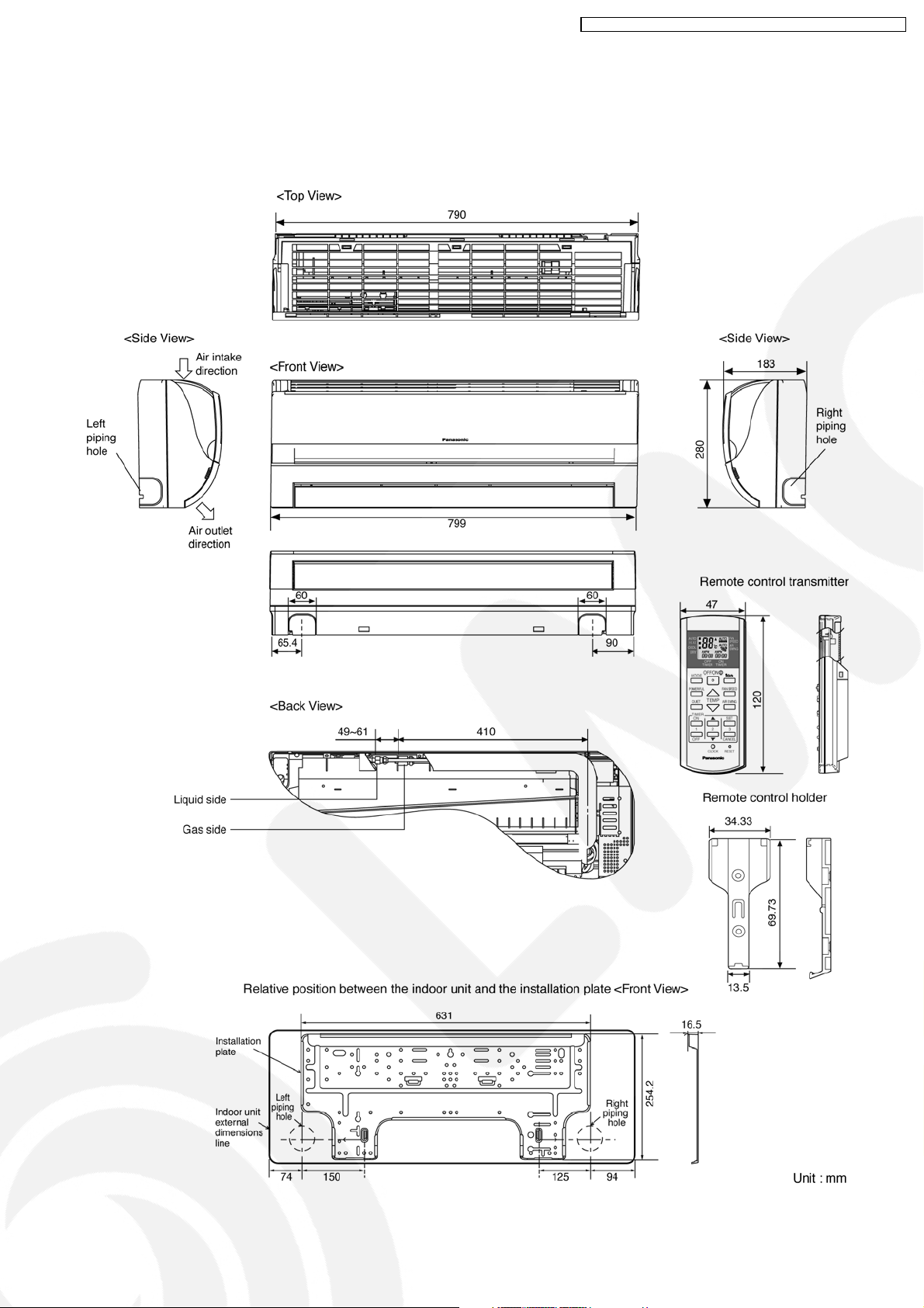
4 Dimensions
4.1. Indoor Unit & Remote Control
4.1.1. CS-V7DKE CS-V9DKE CS-V12DKE
CS-V7DKE CU-V7DKE / CS-V9DKE CU-V9DKE / CS-V12DKE CU-V12DK E
13
Page 14
CS-V7DKE CU-V7DKE / CS-V9DKE CU-V9DKE / CS-V12DKE CU-V12DK E
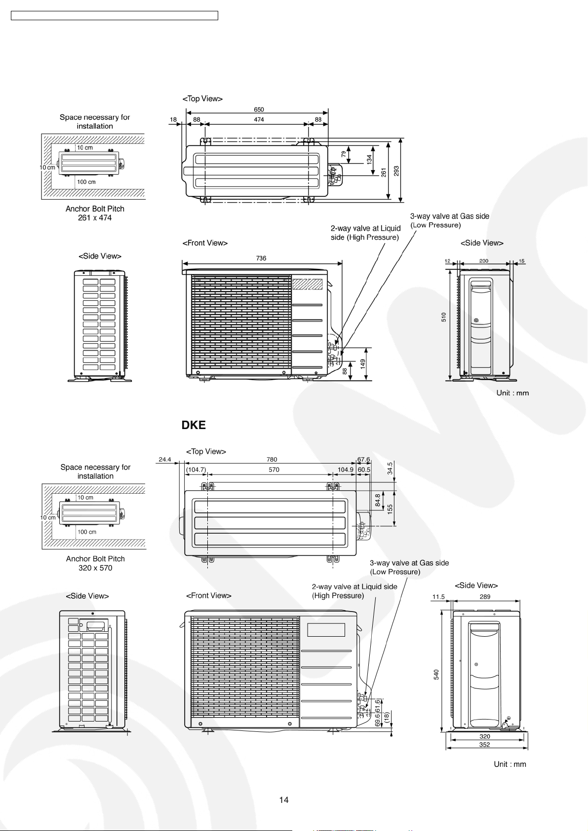
4.2. Outdoor Unit
4.2.1. CU-V7DKE
4.2.2. CU-V9DKE CU-V12DKE
14
Page 15
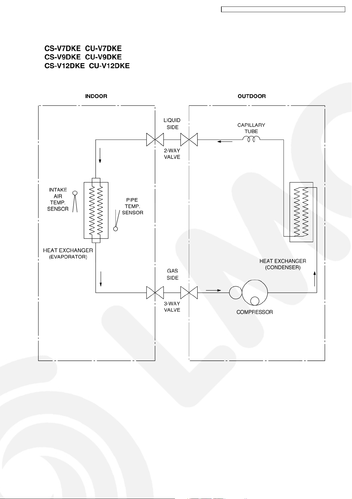
5 Refrigeration Cycle Diagram
CS-V7DKE CU-V7DKE / CS-V9DKE CU-V9DKE / CS-V12DKE CU-V12DK E
15
Page 16

CS-V7DKE CU-V7DKE / CS-V9DKE CU-V9DKE / CS-V12DKE CU-V12DK E
6 Block Diagram
16
Page 17

7 Wiring Diagram
CS-V7DKE CU-V7DKE / CS-V9DKE CU-V9DKE / CS-V12DKE CU-V12DK E
17
Page 18
CS-V7DKE CU-V7DKE / CS-V9DKE CU-V9DKE / CS-V12DKE CU-V12DK E
8 Operation Details
8.1. Cooling Operation
• Cooling operation can be set using remote control.
• This operation is applied to cool down the room temperature reaches the setting temperature set on the remote control.
• The remote control setting temperature, which takes the reading of intake air temperature sensor, can be adjusted from 16°C
to 30°C.
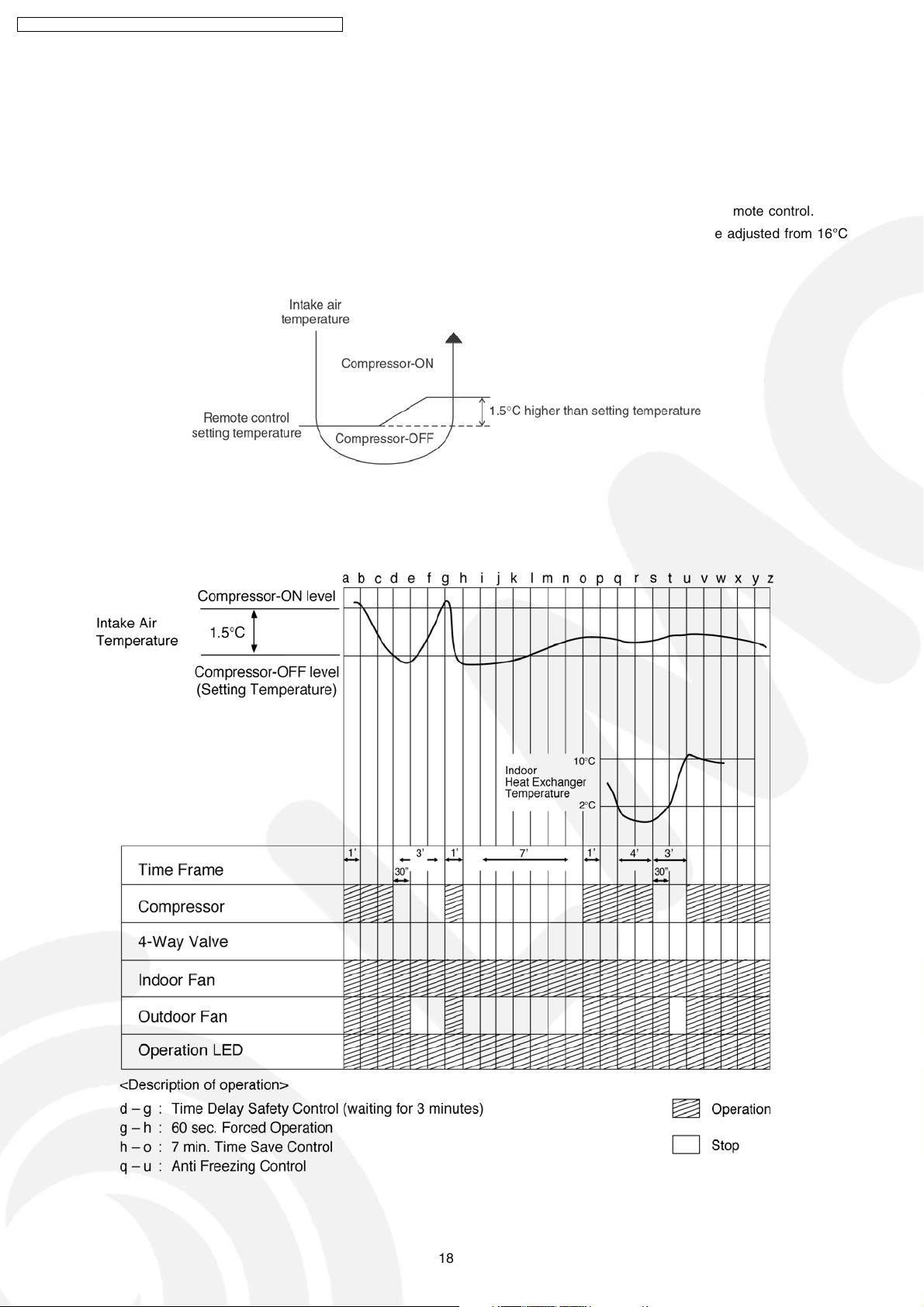
• During cooling operation, the compressor will stop running and restart as shown in below figure.
8.1.1. Cooling Operation Time Diagram
18
Page 19
CS-V7DKE CU-V7DKE / CS-V9DKE CU-V9DKE / CS-V12DKE CU-V12DK E
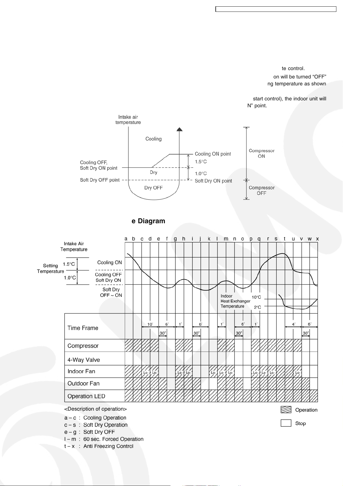
8.2. Soft Dry Operation
• Soft Dry operation can be set using remote control.
• Soft Dry operation is applied to dehumidify and to perform a gentle cooling to the room.
• This operation starts when the intake air temperature sensor reaches the setting temperature on the remote control.
• When operation begins, Soft Dry will be switched “ON” for a maximum 10 minutes, then Soft Dry operation will be turned “OFF”
for a minimum 6 minutes. After that, the Soft Dry operation will be “ON” and “OFF” based on the setting temperature as shown
in below figure.
• However after 3 minutes of compressor off, during Soft Dry “OFF” (within 6 minutes Soft Dry restart control), the indoor unit will
start to operate at normal Cooling mode if the intake temperature is higher than Cooling “ON” point.
8.2.1. Soft Dry Operation Time Diagram
19
Page 20
CS-V7DKE CU-V7DKE / CS-V9DKE CU-V9DKE / CS-V12DKE CU-V12DK E
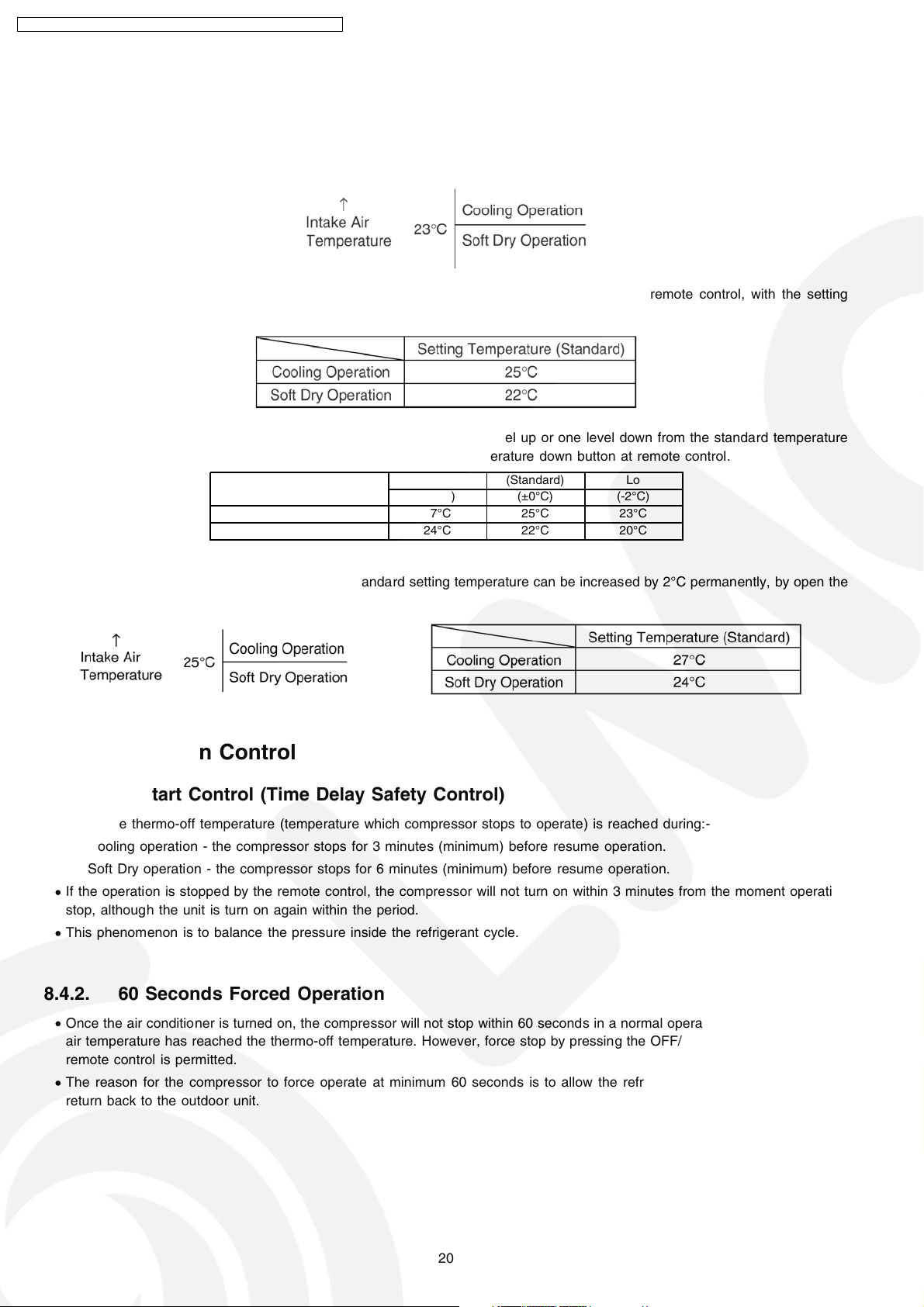
8.3. Automatic Operation
• Automatic operation can be set using remote control.
• This operation starts to operate with indoor fan at SLo speed for 20 seconds to judge the intake air temperature.
• After judged the temperature, the operation mode is determined by referring to the below standard.
• Then, the unit start to operate at determined operation mode, until it is switched off using remote control, with the setting
temperature as shown in below table.
• The setting temperature for all the operations can be changed one level up or one level down from the standard temperature
as shown in below table by pressing on the temperature up or temperature down button at remote control.
Operation Hi (Standard) Lo
(+2°C) (±0°C) (-2°C)
Cooling 27°C 25°C 23°C
Soft Dry 24°C 22°C 20°C
• The operation mode judging temperature and standard setting temperature can be increased by 2°C permanently, by open the
circuit of JX1 at indoor electronic controller.
8.4. Operation Control
8.4.1. Restart Control (Time Delay Safety Control)
• When the thermo-off temperature (temperature which compressor stops to operate) is reached during:-
− Cooling operation - the compressor stops for 3 minutes (minimum) before resume operation.
− Soft Dry operation - the compressor stops for 6 minutes (minimum) before resume operation.
• If the operation is stopped by the remote control, the compressor will not turn on within 3 minutes from the moment operation
stop, although the unit is turn on again within the period.
• This phenomenon is to balance the pressure inside the refrigerant cycle.
8.4.2. 60 Seconds Forced Operation
• Once the air conditioner is turned on, the compressor will not stop within 60 seconds in a normal operation although the intake
air temperature has reached the thermo-off temperature. However, force stop by pressing the OFF/ON operation button at the
remote control is permitted.
• The reason for the compressor to force operate at minimum 60 seconds is to allow the refrigerant oil run in a full cycle and
return back to the outdoor unit.
20
Page 21
CS-V7DKE CU-V7DKE / CS-V9DKE CU-V9DKE / CS-V12DKE CU-V12DK E
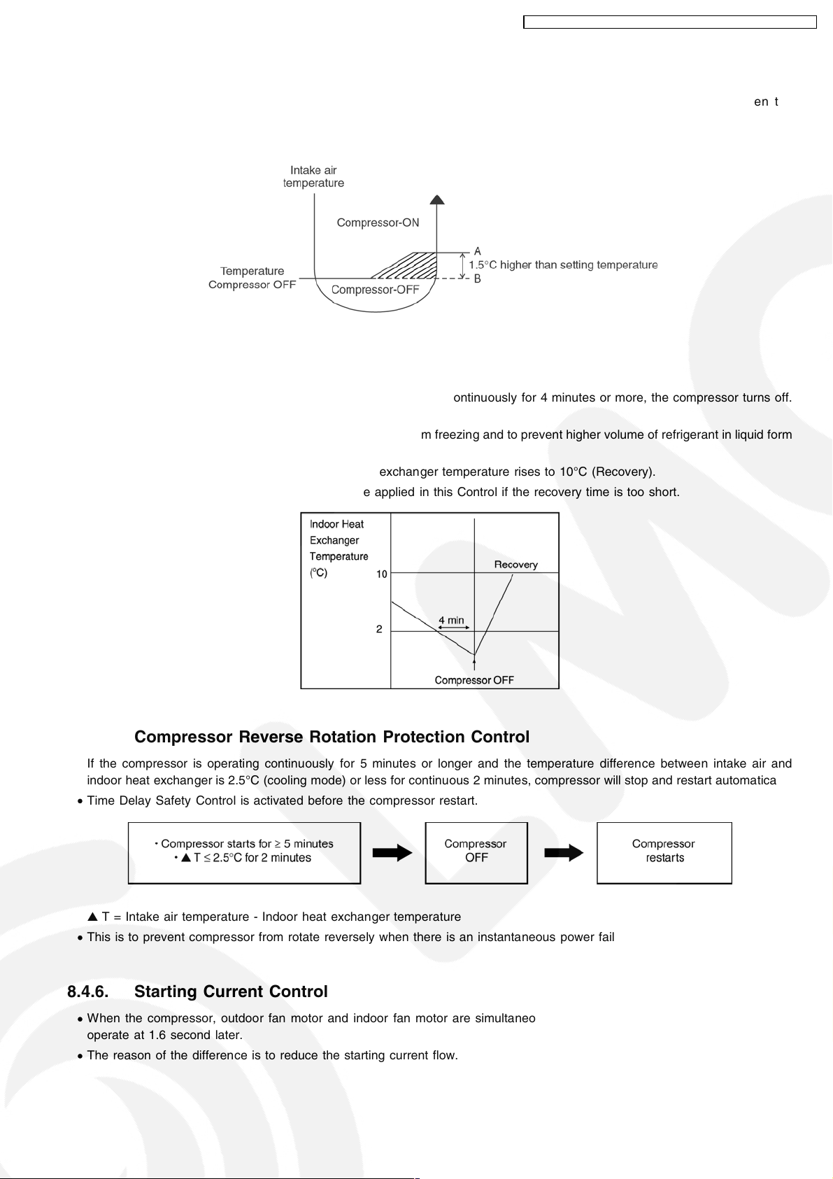
8.4.3. 7 Minutes Time Save Control
• The compressor will start automatically if it has stopped for 7 minutes and the intake air temperature falls between the
compressor ON temperature (A) and compressor OFF temperature (B) during the period.
• This phenomenon is to reduce the built up humidity inside a room.
8.4.4. Anti-Freezing Control
• If the temperature of the indoor heat exchanger falls below 2°C continuously for 4 minutes or more, the compressor turns off.
The fan speed setting remains the same.
• This phenomenon is to protect the indoor heat exchanger from freezing and to prevent higher volume of refrigerant in liquid form
returning to the compressor.
• Compressor will restart again when the indoor heat exchanger temperature rises to 10°C (Recovery).
• Restart control (Time Delay Safety Control) will be applied in this Control if the recovery time is too short.
8.4.5. Compressor Reverse Rotation Protection Control
• If the compressor is operating continuously for 5 minutes or longer and the temperature difference between intake air and
indoor heat exchanger is 2.5°C (cooling mode) or less for continuous 2 minutes, compressor will stop and restart automatically.
• Time Delay Safety Control is activated before the compressor restart.
▲ T = Intake air temperature - Indoor heat exchanger temperature
• This is to prevent compressor from rotate reversely when there is an instantaneous power failure.
8.4.6. Starting Current Control
• When the compressor, outdoor fan motor and indoor fan motor are simultaneously started, the indoor fan motor will start to
operate at 1.6 second later.
• The reason of the difference is to reduce the starting current flow.
21
Page 22
CS-V7DKE CU-V7DKE / CS-V9DKE CU-V9DKE / CS-V12DKE CU-V12DK E
8.4.7. Anti-Dew Formation Control
• Purpose is to prevent dew formation on indoor unit air discharge area.
• When room temperature is constant (±1°C) the following conditions occur for 30 minutes continuously, anti-dew formation will
activate:
− Remote Control setting temperature is less than 25°C.
− Compressor is on.
− Cooling operation mode.
− Indoor Fan motor operate at Low fan speed (CLo, Lo- or QLo).
• This control is cancelled immediately when above condition is changed, or Powerful button is pressed.
• Anti-Dew formation is control by:
1. CLo fan is changed to HLo fan.
2. QLo fan is changed to HLo fan.
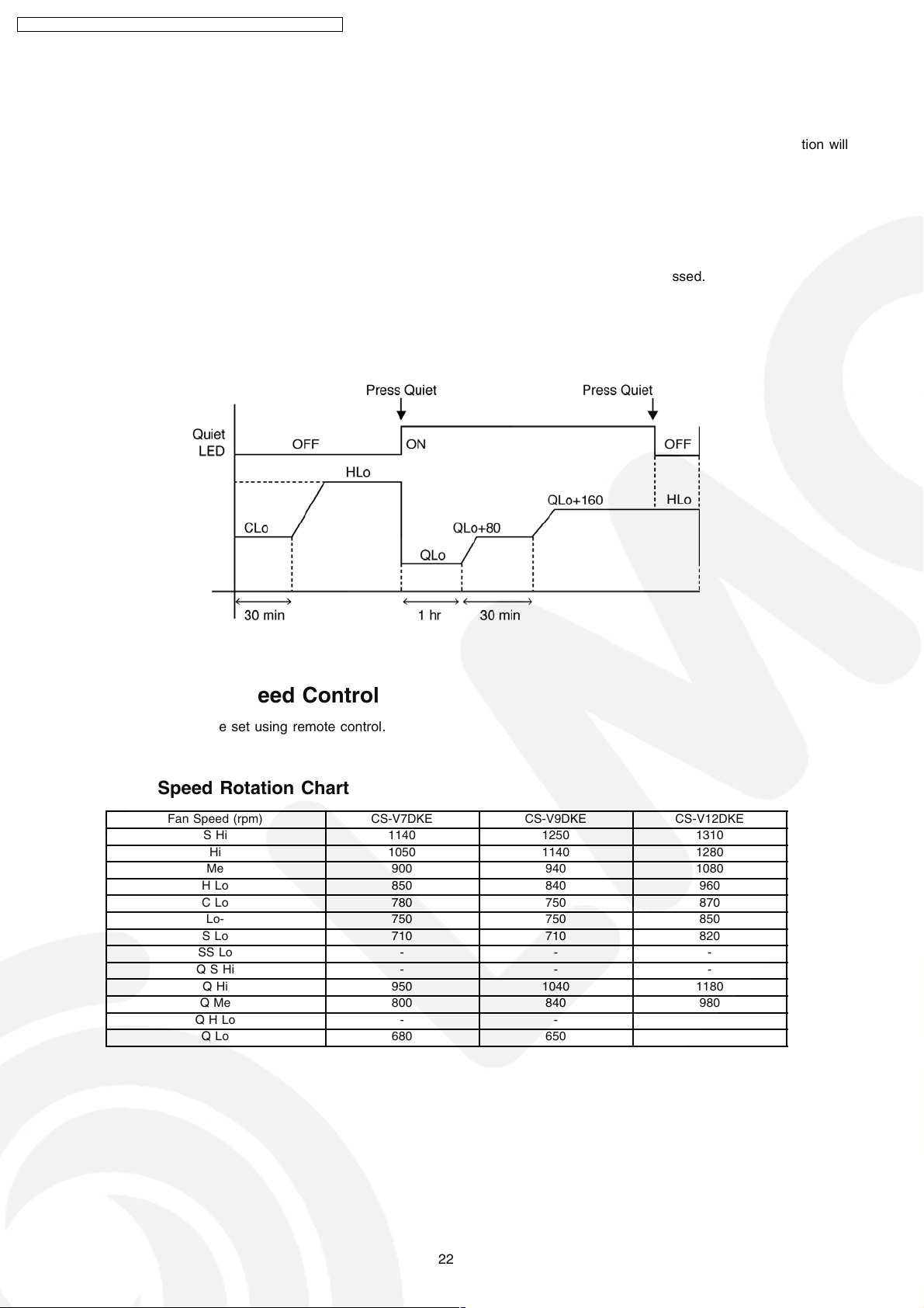
8.5. Indoor Fan Speed Control
• Indoor Fan Speed can be set using remote control.
8.5.1. Fan Speed Rotation Chart
Fan Speed (rpm) CS-V7DKE CS-V9DKE CS-V12DKE
SHi 1140 1250 1310
Hi 1050 1140 1280
Me 900 940 1080
HLo 850 840 960
CLo 780 750 870
Lo- 750 750 850
SLo 710 710 820
SS Lo - - -
QSHi - - -
QHi 950 1040 1180
QMe 800 840 980
QHLo - - -
QLo 680 650 770
22
Page 23
CS-V7DKE CU-V7DKE / CS-V9DKE CU-V9DKE / CS-V12DKE CU-V12DK E
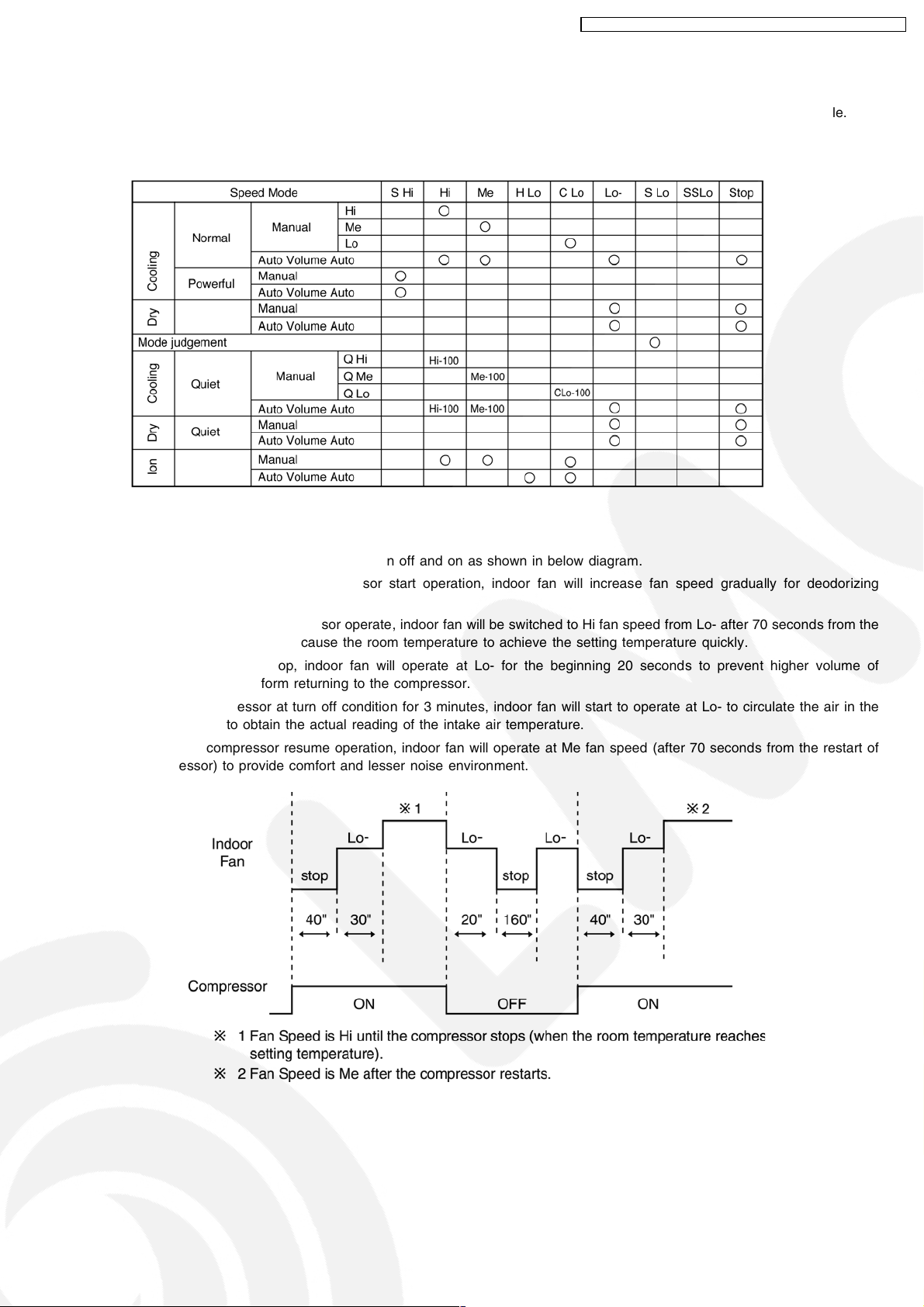
8.5.2. Automatic Fan Speed Control
• When set to Auto Fan Speed, the fan speed is adjusted between maximum and minimum setting as shown in the table.
− Fan speed rotates in the range of Hi, Me and Lo-.
− Deodorizing Control will be activated.
− Auto Fan Speed during cooling operation:
1. Indoor fan will rotate alternately between off and on as shown in below diagram.
2. At the beginning of each compressor start operation, indoor fan will increase fan speed gradually for deodorizing
purpose.
3. For the first time the compressor operate, indoor fan will be switched to Hi fan speed from Lo- after 70 seconds from the
start of compressor. This cause the room temperature to achieve the setting temperature quickly.
4. During compressor stop, indoor fan will operate at Lo- for the beginning 20 seconds to prevent higher volume of
refrigerant in liquid form returning to the compressor.
5. After the compressor at turn off condition for 3 minutes, indoor fan will start to operate at Lo- to circulate the air in the
room. This is to obtain the actual reading of the intake air temperature.
6. When the compressor resume operation, indoor fan will operate at Me fan speed (after 70 seconds from the restart of
compressor) to provide comfort and lesser noise environment.
23
Page 24
CS-V7DKE CU-V7DKE / CS-V9DKE CU-V9DKE / CS-V12DKE CU-V12DK E
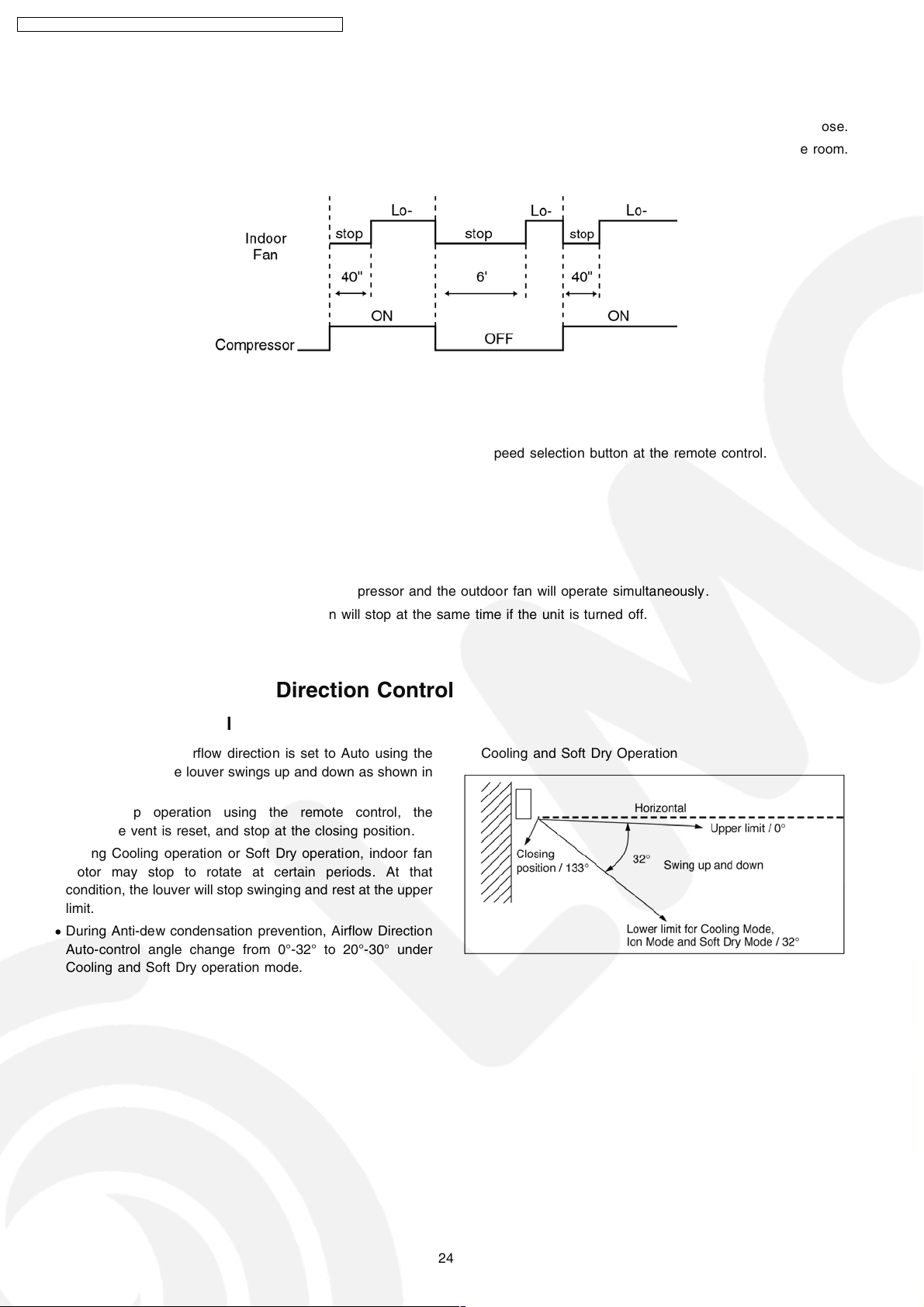
• Auto Fan Speed during Soft Dry operation:
1. Indoor fan will rotate alternately between off and Lo-.
2. At the beginning of each compressor start operation, indoor fan will increase fan speed gradually for deodorizing purpose.
3. When compressor at turn off condition for 6 minutes, indoor fan will start fan speed at Lo- to circulate the air in the room.
This is to obtain the actual reading of intake air temperature.
8.5.3. Manual Fan Speed Control
• Manual fan speed adjustment can be carried out by using the Fan Speed selection button at the remote control.
• There are 3 types of fan speed settings: Lo, Me, Hi.
8.6. Outdoor Fan Speed Control
• There is only one speed for outdoor fan motor.
• When the air conditioner is turned on, the compressor and the outdoor fan will operate simultaneously .
• Likewise, both compressor and outdoor fan will stop at the same time if the unit is turned off.
8.7. Vertical Airflow Direction Control
8.7.1. Auto Control
• When the vertical airflow direction is set to Auto using the
remote control, the louver swings up and down as shown in
the diagram.
• When stop operation using the remote control, the
discharge vent is reset, and stop at the closing position.
• During Cooling operation or Soft Dry operation, indoor fan
motor may stop to rotate at certain periods. At that
condition, the louver will stop swinging and rest at the upper
limit.
• During Anti-dew condensation prevention, Airflow Direction
Auto-control angle change from 0°-32° to 20°-30° under
Cooling and Soft Dry operation mode.
Cooling and Soft Dry Operation
24
Page 25

8.7.2. Manual Control
CS-V7DKE CU-V7DKE / CS-V9DKE CU-V9DKE / CS-V12DKE CU-V12DK E
• When the vertical airflow direction is set to Manual using the
remote control, the automatic airflow is released and the
airflow direction louver move up and down in the range
shown in the diagram.
• The louver can be adjusted by pressing the button to the
desired louver position .
• When stop operation using the remote control, the
discharge vent is reset, and stop at the closing position.
• During Anti-dew condensation prevention, Airflow Direction
Manual control angle change from 10°,15°,20°,26°,32° to
22°,24°,26°,28°,30° under Cooling and Soft Dry operation
mode.
Cooling and Soft Dry Operation
8.8. Horizontal Airflow Direction Control
• The horizontal airflow direction louvers can be adjusted manually by hand.
8.9. Powerful Operation
• The Powerful operation is to achieve the setting temperature quickly.
• When Powerful operation is set, the setting temperature will be automatically decreased 3°C internally against the present
setting temperature (Lower temperature limit: 16°C).
• This operation automatically will be running under SHi Fan Speed (Cooling).
• Vertical Airflow Direction:-
-In“Manual” setting, the vane will automatically shift down 10° lower than previous.
-In“Auto” setting, the vane will automatically swing up and down. However the lower limit will be shifted 10° downward.
• Powerful operation stops when:-
− Powerful operation has operate for 15 minutes.
− Powerful button is pressed again.
− Quiet button is pressed.
− Stopped by OFF/ON operation button.
− Timer OFF activates.
− Operating mode is changed.
8.10. Quiet Operation
• The Quiet operation is to provide quiet cooling operation conditio n compare to normal operation.
(Cooling and Soft Dry Operation condition)
• Once the Quiet Mode is set at the remote control, Quiet Mode LED illuminates. The sound level will reduce either around
2 dB(A) for Lo fan speed or 3 dB(A) for Hi/Me fan speed against the present sound level operation.
• Dew formation become severe at Quiet Lo cool, therefore Quiet Lo cool is operated only 1hr 30 min (1hr QLo, 30 min QLo
+ 80 rpm). After that, it goes back to QLo+160 (However Quiet LED remains on).
25
Page 26

CS-V7DKE CU-V7DKE / CS-V9DKE CU-V9DKE / CS-V12DKE CU-V12DK E
• Manual Fan Speed: -
− RPM control during Lo cool
− RPM control during Hi & Me cool
• Auto Fan Speed:-
− Cooling operation
− Soft Dry operation
• Quiet operation stops when:-
− Quiet button is pressed again.
− Powerful button is pressed.
− Stopped by OFF/ON operation button.
− Timer OFF activates.
26
Page 27

CS-V7DKE CU-V7DKE / CS-V9DKE CU-V9DKE / CS-V12DKE CU-V12DK E
8.11. Ionizer Operation
• The Ionizer operation is to provide fresh air effect to user by producing minus ion in discharge air.
8.11.1. Operation Control
1. Ionizer individu al operation
a. When air-conditioner unit is at “OFF” condition (standby) and ION operation button at the remote control is pressed, the
Ionizer and indoor fan operations will turn on. Only ION LED will illuminates. Power LED maintain off. (1 → 2)
b. Ionizer individu al operation can be turned off by pressing the ION button again. (2 → 1)
c. Fan speed can be adjusted later by customer during this operation.
d. Vertical airflow direction can be adjusted using remote control during Ionizer individual operation.
e. During Ionizer individual operation, operated mode (Auto, Cool, Dry) can be activated by turning on the OFF/ON operation
button. (2 → 4)
f. If power failure occur during Ionizer individual operation, after power resume, Ionizer operation will be activated immediately.
g. When the Ionizer circuit feedback process error occur for 24 times (about 11hr 30 min.), Ionizer and Air Circulation
operations will turn off with ION LED blinks continuously.
(For details, please refer to Ionizer Error detection control)
2. Operation mode & Ionizer operation.
a. When air-conditioner unit is at “ON” condition and ION operation button at the remote control is pressed, the Ionizer
operation will turn on. ION & Power LED will illuminate. (3 → 4)
b. Ionizer operation stops when:
• ION operation button is press again.
• Stopped by OFF/ON operation button.
• Timer OFF activates.
• Ionizer circuit feedback signal shows error.
c. Ionizer operation status is not memorized when the air conditio ner has been switched off. The air-conditioner will operate
without ionizer operation when it is turned on again. However, if power failure occurs during Ionizer operation together with
Cooling operation, air-conditioner will start to operate at Cooling operation with Ionizer operation when the power is
resumed.
27
Page 28
CS-V7DKE CU-V7DKE / CS-V9DKE CU-V9DKE / CS-V12DKE CU-V12DK E
8.11.2. Error Detection Control
• The error detection control is to inform user that error occurs at ionizer system and repairing job will be needed.
• There are two types of error detection control:
a. When Ionizer is ON
− If ionizer feedback = Lo for 24 times within 11hr 30min, ION LED blinks continuously.
b. When ionizer is OFF
− If ionizer feedback = Hi, ION LED blinks continuously.
• During ionizer at breakdown condition, if ionizer feedback voltage = Lo (become normal), ION LED will stop blinking.
• The error detection control can be reset by:
i) Pressing the OFF/ON operation button to switch the operation OFF.
ii) Pressing the Auto Operation button to force the operation OFF.
iii) Setting the OFF Timer to stop the operation (Not applicable when ionizer is OFF).
8.12. Timer Control
• There are 2 types of timer, ON and OFF timer.
• Both ON and OFF timer can be set by pressing ON or OFF button respectively.
• By pressing ON/OFF operation button, ON Timer or OFF Timer will not be cancelled.
• To cancel the previous timer setting, press CANCEL button.
• To activate the previous timer setting, press SET button once again.
• If main power supply is switched off, the timer setting will be cancelled.
8.12.1. ON Timer
• When ON Timer is set by using the remote control, the unit will start to operate slightly before the set time, so that the room will
reach nearly to the set temperature by the set time.
• For Cooling and Soft Dry operation, the operation will start 15 minutes before the set time.
• For Automatic operation, the indoor fan will operate at SLo speed for 20 seconds, 30 minutes before the set time to detect the
intake air temperature to determine the operation mode. The operation indication lamp will blink at this time.
8.12.2. OFF Timer
• When OFF Timer is set by using the remote control, the unit will stop operate according to the desired setting.
8.13. Random Auto Restart Control
• If there is a power failure during operation, the air conditio ner will automatically restart after 3 to 4 minutes when the power is
resumed.
• It will start with previous operation mode and airflow direction.
• If there are more than one air conditioner unit in operation and power failure occur, restart time for each unit to operate will be
decided randomly using 4 parameters:- intake air temperature, setting temperature, fan speed and air swing louver position.
• This Random Auto Restart Control is not available when Timer is set.
• This control can be omitted by open the circuit of JX2. (Refer Circuit Diagram)
8.14. Remote Control Signal Receiving Sound
• Long beep sound will be heard when:-
− Stopping the air conditioner using OFF/ON operation button.
− Stopping the Quiet Mode.
− Stopping the Powerful Mode.
− Stopping the Ion Mode.
• Short beep sound will be heard for others setting.
28
Page 29
9 Operating Instructions
Thank you for purchasing Panasonic Air Conditioner
CS-V7DKE CU-V7DKE / CS-V9DKE CU-V9DKE / CS-V12DKE CU-V12DK E
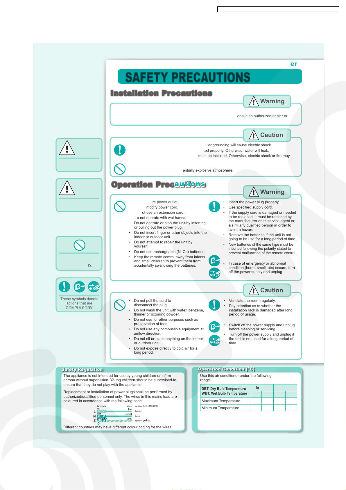
■ Definition
To prevent personal injury,
injury to others and property
damage, the following
instructions must be
followed.
Incorrect operation due to
failure to follow instructions
will cause harm or damage,
the seriousness of which is
classifi ed as below:
Warning
This sign warns of death
or serious injury.
Caution
This sign warns of injury
or damage to property.
The instructions to be
followed are classifi ed by
the following symbols:
This symbol denotes
an action that is
PROHIBITED.
SAFETY PRECAUTIONS
Installation Precautions
Warning
Do not install, remove and reinstall the unit by yourself.
• Improper installation will cause leakage, electric shock or fi re. Please consult an authorized dealer or
specialist for the installation work.
Caution
• This air conditioner must be earthed. Improper grounding will cause electric shock.
• Ensure that the drainage piping is connected properly. Otherwise, water will leak.
• Current leakage protection equipment must be installed. Otherwise, electric shock or fi re may
occur.
• Do not install the unit in a potentially explosive atmosphere.
Operation
• Do not share power outlet.
• Do not modify power cord.
• Do not use an extension cord.
• Do not operate with wet hands.
• Do not operate or stop the unit by inserting
or pulling out the power plug.
• Do not insert fi nger or other objects into the
indoor or outdoor unit.
• Do not attempt to repair the unit by
yourself.
• Do not use rechargeable (Ni-Cd) batteries.
• Keep the remote control away from infants
and small children to prevent them from
accidentally swallowing the batteries.
Precautions
Warning
• Insert the power plug properly.
• Use specifi ed supply cord.
• If the supply cord is damaged or needed
to be replaced, it must be replaced by
the manufacturer or its service agent or
a similarly qualifi ed person in order to
avoid a hazard.
• Remove the batteries if the unit is not
going to be use for a long period of time.
New batteries of the same type must be
•
inserted following the polarity stated to
prevent malfunction of the remote control.
• In case of emergency or abnormal
condition (burnt, smell, etc) occurs, turn
off the power supply and unplug.
These symbols denote
actions that are
COMPULSORY.
• Do not pull the cord to
disconnect the plug.
• Do not wash the unit with water, benzene,
thinner or scouring powder.
• Do not use for other purposes such as
preservation of food.
• Do not use any combustible equipment at
airfl ow direction.
• Do not sit or place anything on the indoor
or outdoor unit.
• Do not expose directly to cold air for a
long period.
Safety Regulation
The appliance is not intended for use by young children or infi rm
person without supervision. Young children should be supervised to
ensure that they do not play with the appliance.
Replacement or installation of power plugs shall be performed by
authorized/qualifi ed personnel only. The wires in this mains lead are
coloured in accordance with the following code:
Different countries may have different colour coding for the wires.
(GB Standard)
Caution
• Ventilate the room regularly.
• Pay attention as to whether the
installation rack is damaged after long
period of usage.
• Switch off the power supply and unplug
before cleaning or servicing.
• Turn off the power supply and unplug if
the unit is not used for a long period of
time.
Operation Condition (OC)
Use this air conditioner under the following temperature
range.
DBT: Dry Bulb Temperature
WBT: Wet Bulb Temperature
Maximum Temperature 32 23 43 26
Minimum Temperature 16 11 16 11
Indoor Outdoor
DBT WBT DBT WBT
29
Page 30

CANCEL
OFF
TIMER
ON
TIMER
FAN
SPEED
AIR
SWING
AUTO
DRY
COOL
MODE
TIMER
ON
123
OFF
CLOCK RESET
SET
CANCEL
TEMP
POWERFUL
FANSPEED
AIR SWING
OFF/ON
QUIET
CS-V7DKE CU-V7DKE / CS-V9DKE CU-V9DKE / CS-V12DKE CU-V12DK E
Note: The illustrations in this manual are for explanation purposes only and may differ from the
actual unit. It is subjected to change without notice for future improvement.
PRODUCT OVERVIEW
I
ndoor Unit
Front panel
Air filter
Airflow direction louver
Discharged air
Outdoor
Air inlet
(side)
Unit
Air inlet
(rear)
Remote Control
LCD display
Operation mode
Powerful operation
Quiet operation
Timer setting
Clock setting
Troubleshooting
● Operation delayed for few minutes after restart.
● Sound like water fl owing during operation.
● Mist emerges from indoor unit.
● Noisy during operations.
● Remote control/display does not work.
● The unit cannot operate.
● Outdoor unit emits water/steam.
Ionizer
Do not touch
during operation
Air outlet
POWERFUL
QUIET
ERPOW
TIM
R
E
ION
Transmitter
Ion operation
Temperature setting
Fan speed selection
Airflow direction
adjustment
Memory reset
■ About
Air intake
Remote Control Preparation
1. Pull out
O
PEN
Supersonic air
purifying device
Action
sound
2. Insert batteries
(AAA or R03)
4. Set
current
time
Operation
mode
Automatic
Operation
Cooling
Operation
Auto OFF/ON
button
3. Press CLOCK button
Receiver
5. Press again to confi rm
• Timer operation will be based on
current time set.
Indicator
QUIET
POWERFUL
ION
TIMERPOWER
SUPER
ALLERU-BUSTER
Off/On
➤ This is a normal self protection control.
➤ Caused by refrigerant fl ow inside.
➤ Condensation effect due to cooling process.
➤ Installation work could be slanted or front panel didn’t close properly.
➤ Check whether batteries are correctly inserted or need replacement.
➤ Check either circuit breaker is tripped, power plug is inserted correctly or
timer is used correctly.
➤ Condensation or evaporation happens at piping surface.
• The batteries can be used for
approximately 1 year.
• The batteries must be
recycled or disposed of
properly.
Remote Control Signal
• Make sure it is not obstructed.
• Maximum distances: 10m.
• Certain fluorescent lights may
interfere with signal transmission.
Consult your dealer.
Auto OFF/ON Button
• To operate the unit if the
remote control is misplaced or
malfunctioning.
Press once
Press until “beep”
• To OFF, press again the Auto OFF/
ON button.
• To switch the remote control signal
receiving sound off or on.
1. Press until “beep” sound and
release.
2. Press again until “beep-beep”
sound and release.
3. Press to switch the sound off or
on.
(Long “beep” - OFF; short “beep”
- ON)
30
Page 31
CS-V7DKE CU-V7DKE / CS-V9DKE CU-V9DKE / CS-V12DKE CU-V12DK E
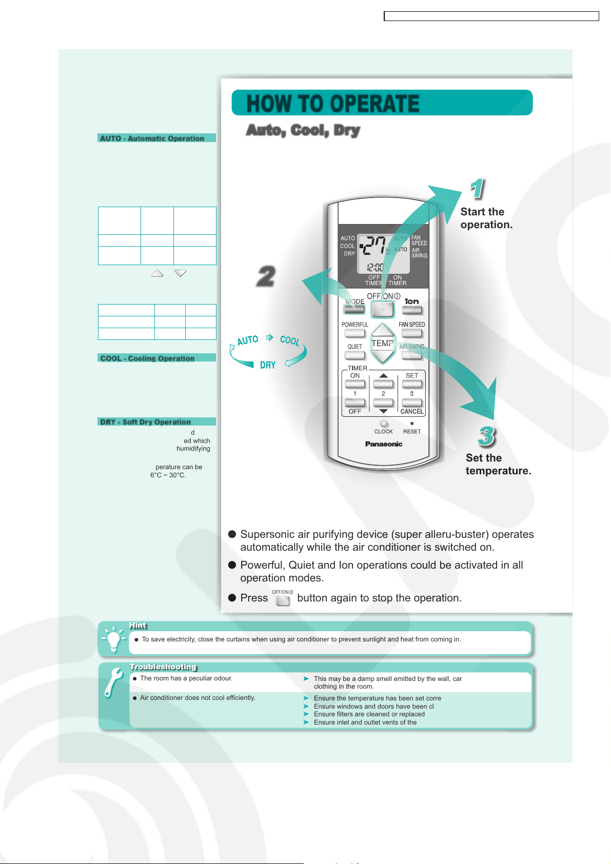
■ Operation Details
AUTO - Automatic Operation
• The unit will automatically select the
operation mode according to the
room temperature.
• Once the operation mode is
selected, the unit will operate at the
standard setting temperature as
shown:
Room
temperature
23°C & above Cool 25°C
Below 23°C Dry 22°C
• You may press or button
to change the standard setting
temperature to “HI” or “LO” as
shown:
Operation mode HI LO
COOL - Cooling Operation
• Enables you to enjoy the cooling
effect at your preferred setting
temperature.
• The range of temperature can be
selected from 16°C ~ 30°C.
Operation
mode
Cool 27°C 23°C
Dry 24°C 20°C
Standard
setting
temperature
HOW TO OPERATE
Auto, Cool, Dry
1
Start the
operation.
2
Select the
desired
operation.
DRY - Soft Dry Operation
• Enables you to set the desired
temperature at low fan speed which
provides you with the dehumidifying
surroundings.
• The range of temperature can be
selected from 16°C ~ 30°C.
Hint
● To save electricity, close the curtains when using air conditioner to prevent sunlight and heat from coming in.
Troubleshooting
● The room has a peculiar odour.
● Air conditioner does not cool effi ciently.
3
Set the
temperature.
● Supersonic air purifying device (super alleru-buster) operates
automatically while the air conditioner is switched on.
● Powerful, Quiet and Ion operations could be activated in all
operation modes.
● Press
OFF/ON
button again to stop the operation.
➤ This may be a damp smell emitted by the wall, carpet, furniture or
clothing in the room.
➤ Ensure the temperature has been set correctly.
➤ Ensure windows and doors have been closed properly.
➤ Ensure fi lters are cleaned or replaced when necessary.
➤ Ensure inlet and outlet vents of the units have not been obstructed.
31
Page 32
CS-V7DKE CU-V7DKE / CS-V9DKE CU-V9DKE / CS-V12DKE CU-V12DK E
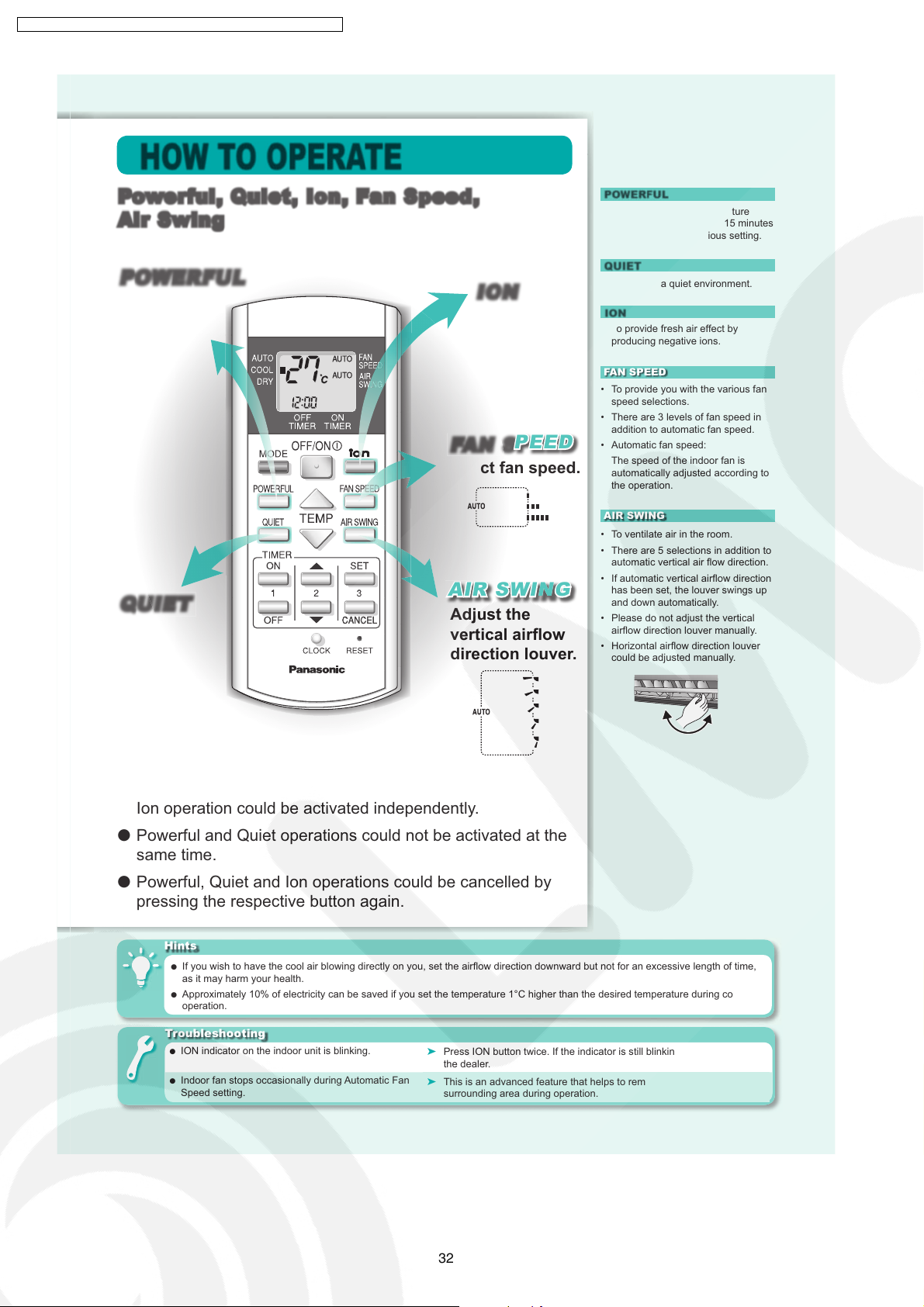
HOW TO OPERATE
Powerful,
Air Swing
POWERFUL
Enables
powerful
operation.
QUIET
Enables quiet
operation.
Quiet,
Ion, Fan Speed,
NION
Enables ion
operation.
N
FAN SPEED
Select fan speed.
AIR SWING
Adjust the
vertical airfl ow
direction louver.
N
■ Operations Details
POWERFUL
• To achieve setting temperature
quickly. It will operate for 15 minutes
and return to the previous setting.
QUIET
• To provide a quiet environment.
ION
• To provide fresh air effect by
producing negative ions.
FAN SPEED
• To provide you with the various fan
speed selections.
• There are 3 levels of fan speed in
addition to automatic fan speed.
• Automatic fan speed:
The speed of the indoor fan is
automatically adjusted according to
the operation.
AIR SWING
• To ventilate air in the room.
• There are 5 selections in addition to
automatic vertical air fl ow direction.
• If automatic vertical airfl ow direction
has been set, the louver swings up
and down automatically.
• Please do not adjust the vertical
airfl ow direction louver manually.
• Horizontal airfl ow direction louver
could be adjusted manually.
● Ion operation could be activated independently.
● Powerful and Quiet operations could not be activated at the
same time.
● Powerful, Quiet and Ion operations could be cancelled by
pressing the respective button again.
Hints
● If you wish to have the cool air blowing directly on you, set the airfl ow direction downward but not for an excessive length of time,
as it may harm your health.
● Approximately 10% of electricity can be saved if you set the temperature 1°C higher than the desired temperature during cooling
operation.
Troubleshooting
● ION indicator on the indoor unit is blinking.
● Indoor fan stops occasionally during Automatic Fan
Speed setting.
➤ Press ION button twice. If the indicator is still blinking, please consult
the dealer.
➤ This is an advanced feature that helps to remove smell from the
surrounding area during operation.
32
Page 33
CS-V7DKE CU-V7DKE / CS-V9DKE CU-V9DKE / CS-V12DKE CU-V12DK E
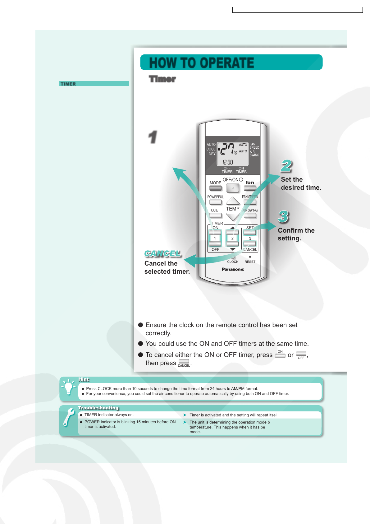
■ Operation Details
TIMER
• Use the ON timer to turn on the air
conditioner at the desired time. This
will give you a cooling environment,
e.g. when you return from work or
wake up.
• When the ON timer is set, operation
will start 15 minutes before the
actual set time.
• Use the OFF timer to stop the air
conditioner operation at the desired
time. This can save electricity while
you are going out or sleeping.
• The set timer will repeat daily once
it is set.
• If there is a power failure, you can
press SET button to restore the
previous setting once the power is
resumed.
• If the timer is cancelled, you can
restore the previous setting by
pressing SET button.
HOW TO OPERATE
Timer
1
Select ON or
OFF timer.
2
Set the
desired time.
3
Confi rm the
setting.
N
CANCEL
Cancel the
selected timer.
● Ensure the clock on the remote control has been set
correctly.
● You could use the ON and OFF timers at the same time.
● To cancel either the ON or OFF timer, press
then press
Hint
● Press CLOCK more than 10 seconds to change the time format from 24 hours to AM/PM format.
● For your convenience, you could set the air conditioner to operate automatically by using both ON and OFF timer.
Troubleshooting
● TIMER indicator always on.
● POWER indicator is blinking 15 minutes before ON
timer is activated.
.
➤ Timer is activated and the setting will repeat itself daily.
➤ The unit is determining the operation mode by sensing the room
temperature. This happens when it has been set to AUTO operation
mode.
or ,
33
Page 34
CS-V7DKE CU-V7DKE / CS-V9DKE CU-V9DKE / CS-V12DKE CU-V12DK E
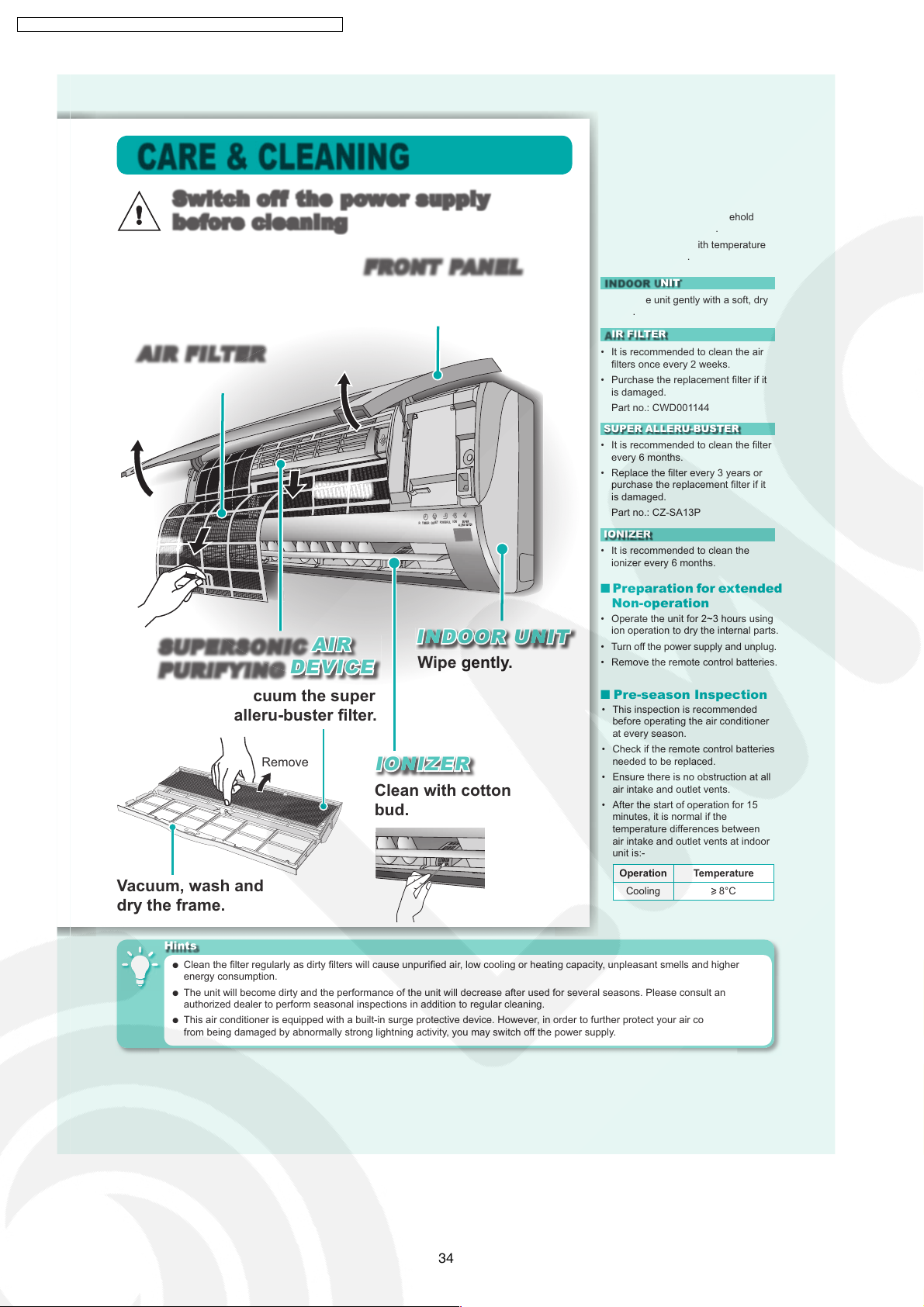
CARE & CLEANING
Switch off the power supply
before cleaning
N
FRONT PANEL
Raise and Pull to remove.
Wash and dry.
AIR FILTER
Vacuum, wash and dry.
Remove
POWERFUL
QUIET
TIMERPOWER
Remove
SUPERSONIC AIR
PURIFYING DEVICE
N
N
Vacuum the super
alleru-buster fi lter.
Remove
Vacuum, wash and
dry the frame.
IONIZER
Clean with cotton
bud.
NNINDOOR UNIT
Wipe gently.
N
■ Washing Instructions
• Do not use benzene, thinner or
scouring powder.
• Use soaps or neutral household
detergent (
• Do not use water with temperature
N
ION
higher than 40°C.
INDOOR UNIT
• Wipe the unit gently with a soft, dry
cloth.
AIR FILTER
• It is recommended to clean the air
fi lters once every 2 weeks.
• Purchase the replacement fi lter if it
is damaged.
Part no.: CWD001144
SUPER ALLERU-BUSTER
• It is recommended to clean the fi lter
every 6 months.
• Replace the fi lter every 3 years or
purchase the replacement fi lter if it
is damaged.
Part no.: CZ-SA13P
IONIZER
• It is recommended to clean the
ionizer every 6 months.
pH7) only.
≃
■ Preparation for extended
Non-operation
• Operate the unit for 2~3 hours using
ion operation to dry the internal parts.
• Turn off the power supply and unplug.
• Remove the remote control batteries.
■ Pre-season Inspection
• This inspection is recommended
before operating the air conditioner
at every season.
• Check if the remote control batteries
needed to be replaced.
• Ensure there is no obstruction at all
air intake and outlet vents.
• After the start of operation for 15
minutes, it is normal if the
temperature differences between
air intake and outlet vents at indoor
unit is:-
Operation Temperature
Cooling
8°C
Hints
● Clean the fi lter regularly as dirty fi lters will cause unpurifi ed air, low cooling or heating capacity, unpleasant smells and higher
energy consumption.
● The unit will become dirty and the performance of the unit will decrease after used for several seasons. Please consult an
authorized dealer to perform seasonal inspections in addition to regular cleaning.
● This air conditioner is equipped with a built-in surge protective device. However, in order to further protect your air conditioner
from being damaged by abnormally strong lightning activity, you may switch off the power supply.
34
Page 35
CS-V7DKE CU-V7DKE / CS-V9DKE CU-V9DKE / CS-V12DKE CU-V12DK E
10 Installation Instructions
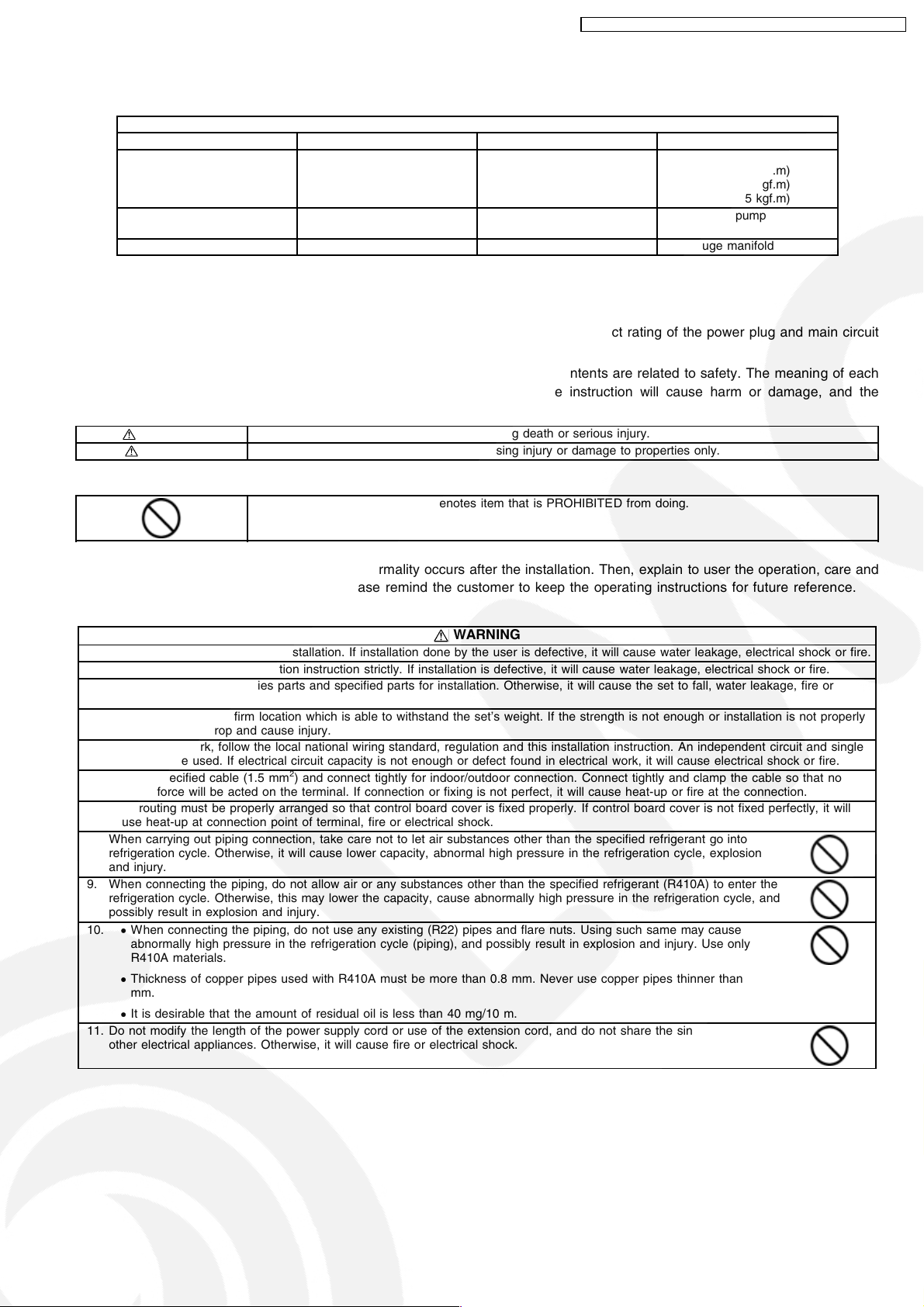
Required tools for Installation Works
1. Philips screw driver 5. Spanner 9. Gas leak detector 13. Multimeter
2. Level gauge 6. Pipe cutter 10. Measuring tape 14. Torque wrench
3. Electric drill, hole core drill
(ø70 mm)
4. Hexagonal wrench (4 mm) 8. Knife 12. Megameter 16. Gauge manifold
7. Reamer 11. Thermometer 15. Vacuum pump
10.1. Safety Precautions
•
Read the following “SAFETY PRECAUTIONS” carefully before installation.
•
Electrical work must be installed by a licensed electrician. Be sure to use the correct rating of the power plug and main circuit
for the model to be installed.
•
The caution items stated here must be followed because these important contents are related to safety. The meaning of each
indication used is as below. Incorrect installation due to ignoring of the instruction will cause harm or damage, and the
seriousness is classified by the following indications.
WARNING
CAUTION
This indication shows the possibility of causing death or serious injury.
This indication shows the possibility of causing injury or damage to properties only.
18 N.m (1.8 kgf.m)
42 N.m (4.2 kgf.m)
55 N.m (5.5 kgf.m)
The items to be followed are classified by the symbols:
Symbol with background white denotes item that is PROHIBITED from doing.
•
Carry out test running to confirm that no abnormality occurs after the installation. Then, explain to user the operation, care and
maintenance as stated in instructions. Please remind the customer to keep the operating instructions for future reference.
WARNING
1. Engage dealer or specialist for installation. If installation done by the user is defective, it will cause water leakage, electrical shock or fire.
2. Install according to this installation instruction strictly. If installation is defective, it will cause water leakage, electrical shock or fire.
3. Use the attached accessories parts and specified parts for installation. Otherwise, it will cause the set to fall, water leakage, fire or
electrical shock.
4. Install at a strong and firm location which is able to withstand the set’s weight. If the strength is not enough or installation is not properly
done, the set will drop and cause injury.
5. For electrical work, follow the local national wiring standard, regulation and this installation instruction. An independent circuit and single
outlet must be used. If electrical circuit capacity is not enough or defect found in electrical work, it will cause electrical shock or fire.
6. Use the specified cable (1.5 mm2) and connect tightly for indoor/outdoor connection. Connect tightly and clamp the cable so that no
external force will be acted on the terminal. If connection or fixing is not perfect, it will cause heat-up or fire at the connection.
7. Wire routing must be properly arranged so that control board cover is fixed properly. If control board cover is not fixed perfectly, it will
cause heat-up at connection point of terminal, fire or electrical shock.
8. When carrying out piping connection, take care not to let air substances other than the specified refrigerant go into
refrigeration cycle. Otherwise, it will cause lower capacity, abnormal high pressure in the refrigeration cycle, explosion
and injury.
9. When connecting the piping, do not allow air or any substances other than the specified refrigerant (R410A) to enter the
refrigeration cycle. Otherwise, this may lower the capacity, cause abnormally high pressure in the refrigeration cycle, and
possibly result in explosion and injury.
10.
•
When connecting the piping, do not use any existing (R22) pipes and flare nuts. Using such same may cause
abnormally high pressure in the refrigeration cycle (piping), and possibly result in explosion and injury. Use only
R410A materials.
•
Thickness of copper pipes used with R410A must be more than 0.8 mm. Never use copper pipes thinner than 0.8
mm.
•
It is desirable that the amount of residual oil is less than 40 mg/10 m.
11. Do not modify the length of the power supply cord or use of the extension cord, and do not share the single outlet with
other electrical appliances. Otherwise, it will cause fire or electrical shock.
35
Page 36

CS-V7DKE CU-V7DKE / CS-V9DKE CU-V9DKE / CS-V12DKE CU-V12DK E
CAUTION
1. The equipment must be earthed. It may cause electrical shock if grounding is not perfect.
2. Do not install the unit at place where leakage of flammable gas may occur. In case gas leaks and accumulates at
surrounding of the unit, it may cause fire.
3. Carry out drainage piping as mentioned in installation instructions. If drainage is not perfect, water may enter the room and damage the
furniture.
ATTENTION
1. Selection of the installation location.
Select a installation location which is rigid and strong enough to support or hold the unit, and select a location for easy maintenance.
2. Power supply connection to the room air conditioner.
Connect the power supply cord of the room air conditioner to the mains using one of the following method.
Power supply point shall be the place where there is ease for access for the power disconnection in case of emergency.
In some countries, permanent connection of this room air conditioner to the power supply is prohibited.
1. Power supply connection to the receptacle using a power plug.
Use an approved 10A power plug with earth pin for the connection to the socket..
2. Power supply connection to a circuit breaker for the permanent connection. Use an approved 16A circuit breaker for the permanent
connection. It must be a double pole switch with a minimum 3.5 mm contact gap.
3. Do not release refrigerant.
Do not release refrigerant during piping work for installation, reinstallation and during repairing a refrigeration parts. Take care of the
liquid refrigerant, it may cause frostbite.
4. Installation work.
It may need two people to carry out the installation work.
5. Do not install this appliance in a laundry room or other location where water may drip from the ceiling, etc.
36
Page 37
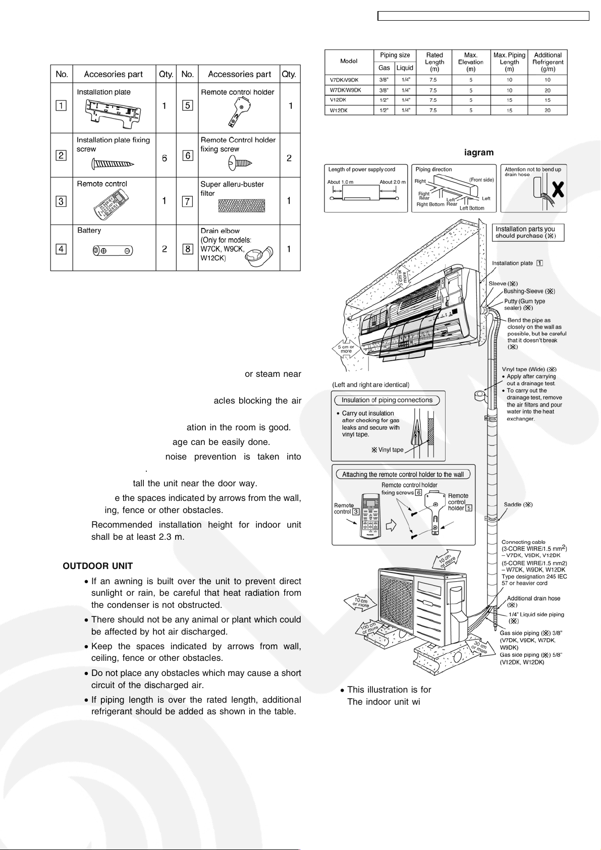
Attached accessories
Applicable piping kit
CZ-3F5, 7BP (V7DK, V9DK, W7DK, W9DK)
CZ-4F5, 7, 10BP (V12DK, W12DK)
CS-V7DKE CU-V7DKE / CS-V9DKE CU-V9DKE / CS-V12DKE CU-V12DK E
Indoor/outdoor Unit Installation Diagram
Select the best location
INDOOR UNIT
• There should not be any heat source or steam near
the unit.
• There should not be any obstacles blocking the air
circulation.
• A place where air circulation in the room is good.
• A place where drainage can be easily done.
• A place where noise prevention is taken into
consideration.
• Do not install the unit near the door way.
• Ensure the spaces indicated by arrows from the wall,
ceiling, fence or other obstacles.
• Recommended installation height for indoor unit
shall be at least 2.3 m.
OUTDOOR UNIT
• If an awning is built over the unit to prevent direct
sunlight or rain, be careful that heat radiation from
the condenser is not obstructed.
• There should not be any animal or plant which could
be affected by hot air discharged.
• Keep the spaces indicated by arrows from wall,
ceiling, fence or other obstacles.
• Do not place any obstacles which may cause a short
circuit of the discharged air.
• If piping length is over the rated length, additional
refrigerant should be added as shown in the table.
• This illustration is for explanation purposes only.
The indoor unit will actually face a different way.
37
Page 38
CS-V7DKE CU-V7DKE / CS-V9DKE CU-V9DKE / CS-V12DKE CU-V12DK E
10.2. Indoor Unit
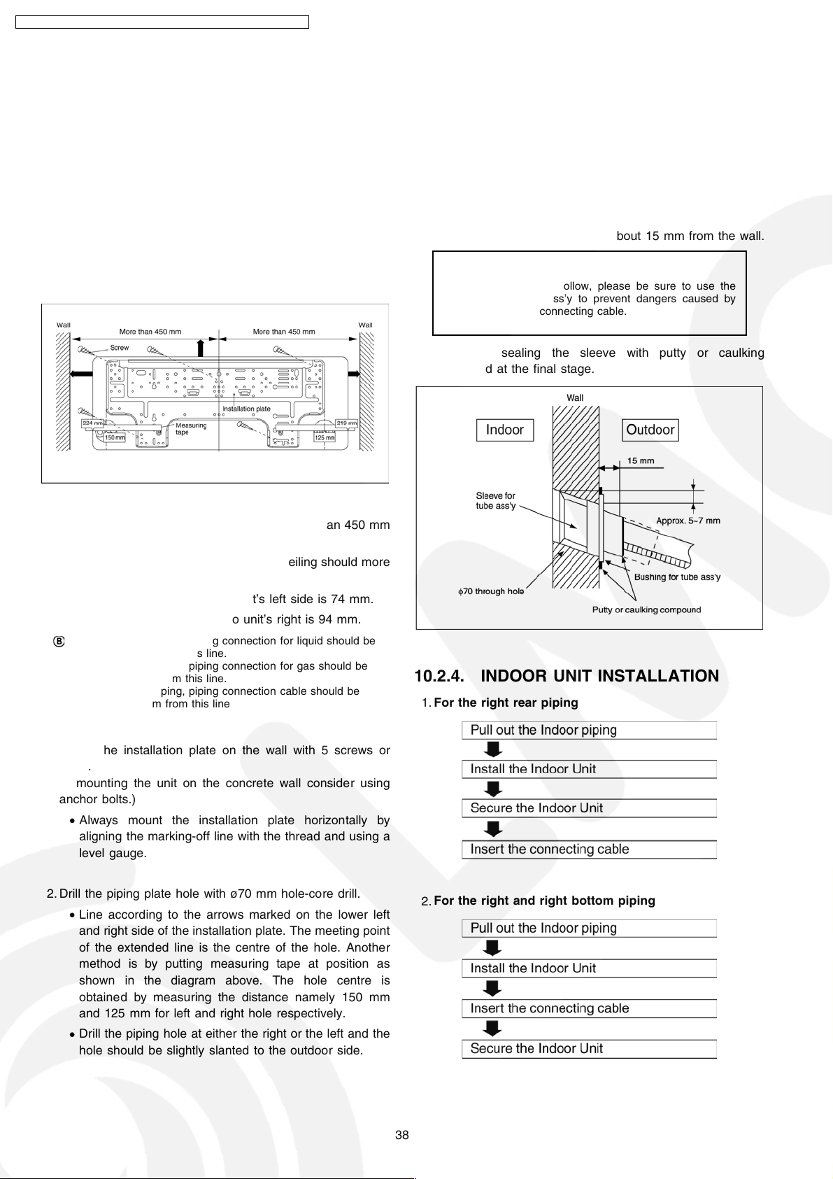
10.2.1. SELECT THE BEST LOCATION
(Refer to “Select the best location”
section)
10.2.2. HOW TO FIX INSTALLATION
PLATE
The mounting wall is strong and solid enough to prevent it from
the vibration.
10.2.3. TO DRILL A HOLE IN THE WALL
AND INSTALL A SLEEVE OF
PIPING
1. Insert the piping sleeve to the hole.
2. Fix the bushing to the sleeve.
3. Cut the sleeve until it extrudes about 15 mm from the wall.
Caution
When the wall is hollow, please be sure to use the
sleeve for tube ass’y to prevent dangers caused by
mice biting the connecting cable.
4. Finish by sealing the sleeve with putty or caulking
compound at the final stage.
The centre of installation plate should be at more than 450 mm
at right and left of the wall.
The distance from installation plate edge to ceiling should more
than 67 mm.
From installation plate left edge to unit’s left side is 74 mm.
From installation plate right edge to unit’s right is 94 mm.
:
For left side piping, piping connection for liquid should be
about 15 mm from this line.
For left side piping, piping connection for gas should be
:
about 45 mm from this line.
For left side piping, piping connection cable should be
:
about 800 mm from this line
1. Mount the installation plate on the wall with 5 screws or
more.
(If mounting the unit on the concrete wall consider using
anchor bolts.)
• Always mount the installation plate horizontally by
aligning the marking-off line with the thread and using a
level gauge.
2. Drill the piping plate hole with ø70 mm hole-core drill.
• Line according to the arrows marked on the lower left
and right side of the installation plate. The meeting point
of the extended line is the centre of the hole. Another
method is by putting measuring tape at position as
shown in the diagram above. The hole centre is
obtained by measuring the distance namely 150 mm
and 125 mm for left and right hole respectively.
• Drill the piping hole at either the right or the left and the
hole should be slightly slanted to the outdoor side.
10.2.4. INDOOR UNIT INSTALLATION
For the right rear piping
1.
For the right and right bottom piping
2.
38
Page 39
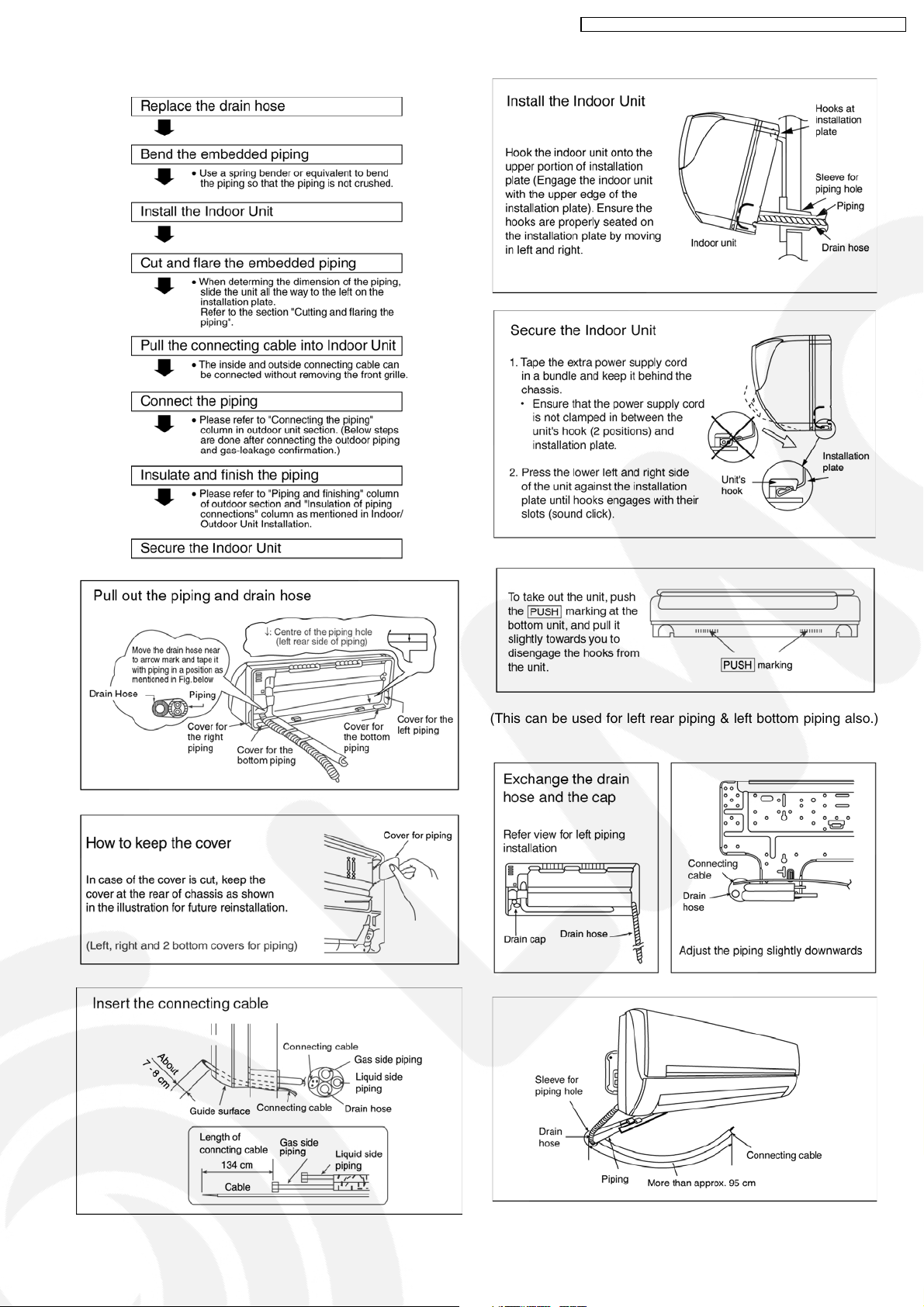
For the embedded piping
3.
CS-V7DKE CU-V7DKE / CS-V9DKE CU-V9DKE / CS-V12DKE CU-V12DK E
(This can be used for left rear piping & left bottom piping also.)
39
Page 40
CS-V7DKE CU-V7DKE / CS-V9DKE CU-V9DKE / CS-V12DKE CU-V12DK E
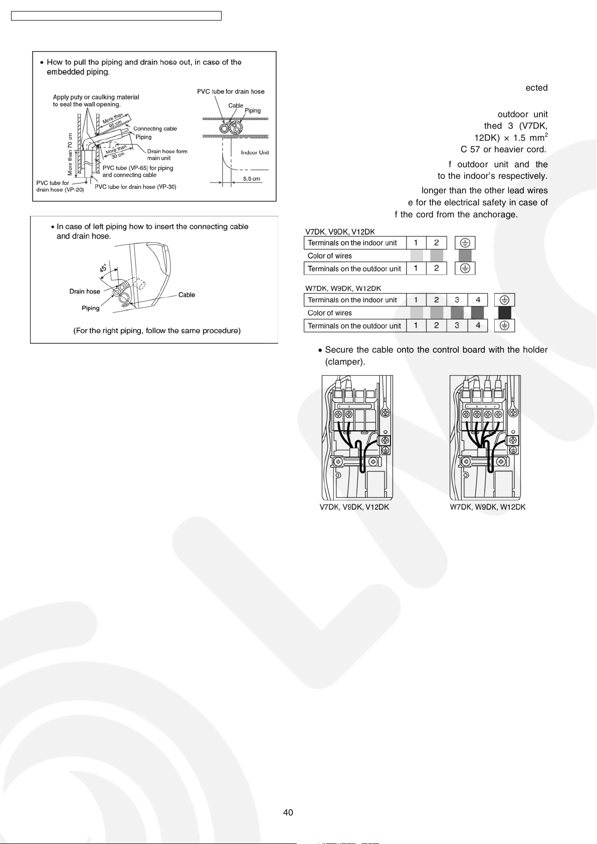
10.2.5. CONNECT THE CABLE TO THE
INDOOR UNIT
1. The inside and outside connecting cable can be connected
without removing the front grille.
2. Connecting cable between indoor unit and outdoor unit
shall be approved polychloroprene sheathed 3 (V7DK,
V9DK, V12DK) or 5 (W7DK, W9DK, W12DK) × 1.5 mm
flexible cord, type designation 245 IEC 57 or heavier cord.
• Ensure the color of wires of outdoor unit and the
terminal Nos. are the same to the indoor’s respectively.
• Earth lead wire shall be longer than the other lead wires
as shown in the figure for the electrical safety in case of
the slipping out of the cord from the anchorage.
2
• Secure the cable onto the control board with the holder
(clamper).
40
Page 41
CS-V7DKE CU-V7DKE / CS-V9DKE CU-V9DKE / CS-V12DKE CU-V12DK E
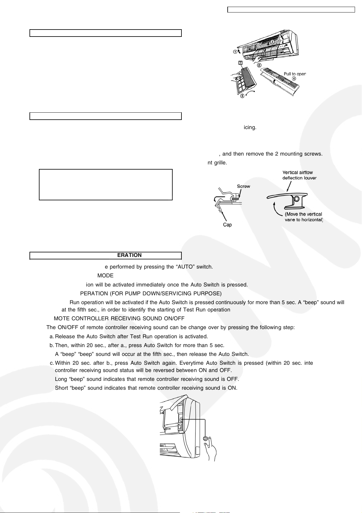
INSTALLATION OF SUPER ALLERU-BUSTER FILTER
1. Open the front panel.
2. Remove the air filter.
3. Remove Supersonic air purifying device.
4. Open the Supersonic air purifyin g device frame.
5. Insert the super alleru-buster filter and close the Supersonic
air purifying device frame as show in illustration at right.
HOW TO TAKE OUT FRONT GRILLE
Please follow the steps below to take out front grille if necessary such as when servicing.
1. Open the intake grille and remove the screw at the front of the front grille.
2. Set the vertical airflow direction louvers to the horizontal position.
3. Slide down the 2 caps on the front grille as shown in the illustration below, and then remove the 2 mounting screws.
4. Pull the lower section of the front grille towards you to remove the front grille.
When reinstalling the front grille, first set the vertical
airflow direction louver to the horizontal position and
then carry out above steps 2 - 3 in the reverse order.
AUTO SWITCH OPERATION
The below operations will be performed by pressing the “AUTO” switch.
1. AUTO OPERATION MODE
The Auto operation will be activated immediately once the Auto Switch is pressed.
2. TEST RUN OPERATION (FOR PUMP DOWN/SERVICING PURPOSE)
The Test Run operation will be activated if the Auto Switch is pressed continuously for more than 5 sec. A “beep” sound will
occur at the fifth sec., in order to identify the starting of Test Run operation
3. REMOTE CONTROLLER RECEIVING SOUND ON/OFF
The ON/OFF of remote controller receiving sound can be change over by pressing the following step:
a. Release the Auto Switch after Test Run operation is activated.
b. Then, within 20 sec., after a., press Auto Switch for more than 5 sec.
A “beep”“beep” sound will occur at the fifth sec., then release the Auto Switch.
c. Within 20 sec. after b., press Auto Switch again. Everytime Auto Switch is pressed (within 20 sec. interval), remote
controller receiving sound status will be reversed between ON and OFF.
Long “beep” sound indicates that remote controller receiving sound is OFF.
Short “beep” sound indicates that remote controller receiving sound is ON.
41
Page 42
CS-V7DKE CU-V7DKE / CS-V9DKE CU-V9DKE / CS-V12DKE CU-V12DK E
10.3. Outdoor Unit
10.3.1. SELECT THE BEST LOCATION
(Refer to “Select the best location” section)
10.3.2. INSTALL THE OUTDOOR UNIT
• After selecting the best location, start installation according
to Indoor/Outdoor Unit Installation Diagram.
1. Fix the unit on concrete or rigid frame firmly and horizontally
by bolt nut. (ø10 mm).
2. When installing at roof, please consider strong wind and
earthquake. Please fasten the installation stand firmly with
bolt or nails.
10.3.3. CONNECTING THE PIPING
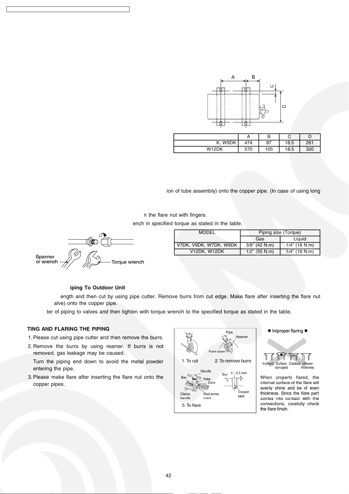
MODEL A B C D
V7DK, V9DK, W7DK, W9DK 474 87 18.5 261
V12DK, W12DK 570 105 18.5 320
Connecting The Piping To Indoor Unit
Please make flare after inserting flare nut (locate at joint portion of tube assembly) onto the copper pipe. (In case of using long
piping)
Connect the piping
• Align the center of piping and sufficiently tighten the flare nut with fingers.
• Further tighten the flare nut with torque wrench in specified torque as stated in the table.
MODEL Piping size (Torque)
Gas Liquid
V7DK, V9DK, W7DK, W9DK 3/8” (42 N.m) 1/4” (18 N.m)
V12DK, W12DK 1/2” (55 N.m) 1/4” (18 N.m)
Connecting The Piping To Outdoor Unit
Decide piping length and then cut by using pipe cutter. Remove burrs from cut edge. Make flare after inserting the flare nut
(located at valve) onto the copper pipe.
Align center of piping to valves and then tighten with torque wrench to the specified torque as stated in the table.
CUTTING AND FLARING THE PIPING
1. Please cut using pipe cutter and then remove the burrs.
2. Remove the burrs by using reamer. If burrs is not
removed, gas leakage may be caused.
Turn the piping end down to avoid the metal powder
entering the pipe.
3. Please make flare after inserting the flare nut onto the
copper pipes.
42
Page 43
CS-V7DKE CU-V7DKE / CS-V9DKE CU-V9DKE / CS-V12DKE CU-V12DK E
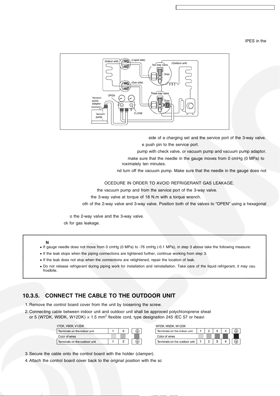
10.3.4. EVACUATION OF THE EQUIPMENT
WHEN INSTALLING AN AIR CONDITIONER, BE SURE TO EVACUATE THE AIR INSIDE THE INDOOR UNIT AND PIPES in the
following procedure.
1. Connect a charging hose with a push pin to the Low and High side of a charging set and the service port of the 3-way valve.
• Be sure to connect the end of the charging hose with the push pin to the service port.
2. Connect the center hose of the charging set to a vacuum pump with check valve, or vacuum pump and vacuum pump adaptor.
3. Turn on the power switch of the vacuum pump and make sure that the needle in the gauge moves from 0 cmHg (0 MPa) to
-76 cmHg (-0.1 MPa). Then evacuate the air approximately ten minutes.
4. Close the Low side valve of the charging set and turn off the vacuum pump. Make sure that the needle in the gauge does not
move after approximately five minutes.
Note: BE SURE TO FOLLOW THIS PROCEDURE IN ORDER TO AVOID REFRIGERANT GAS LEAKAGE.
5. Disconnect the charging hose from the vacuum pump and from the service port of the 3-way valve.
6. Tighten the service port caps of the 3-way valve at torque of 18 N.m with a torque wrench.
7. Remove the valve caps of both of the 2-way valve and 3-way valve. Position both of the valves to “OPEN” using a hexagonal
wrench (4 mm).
8. Mount valve caps onto the 2-way valve and the 3-way valve.
• Be sure to check for gas leakage.
CAUTION
If gauge needle does not move from 0 cmHg (0 MPa) to -76 cmHg (-0.1 MPa), in step 3 above take the following measure:
•
If the leak stops when the piping connections are tightened further, continue working from step 3.
•
If the leak does not stop when the connections are retightened, repair the location of leak.
•
Do not release refrigerant during piping work for installation and reinstallation. Take care of the liquid refrigerant, it may cause
•
frostbite.
10.3.5. CONNECT THE CABLE TO THE OUTDOOR UNIT
1. Remove the control board cover from the unit by loosening the screw.
2. Connecting cable between indoor unit and outdoor unit shall be approved polychloroprene sheathed 3 (V7DK, V9DK, V12DK)
or 5 (W7DK, W9DK, W12DK) × 1.5 mm
3. Secure the cable onto the control board with the holder (clamper).
4. Attach the control board cover back to the original position with the screw.
2
flexible cord, type designation 245 IEC 57 or heavier cord.
43
Page 44
CS-V7DKE CU-V7DKE / CS-V9DKE CU-V9DKE / CS-V12DKE CU-V12DK E
10.3.6. PIPE INSULATION
1. Please carry out insulation at pipe connection portion as mentioned in Indoor/Outdoor Unit Installation Diagram. Please wrap
the insulated piping end to prevent water from going inside the piping.
2. If drain hose or connecting piping is in the room (where dew may form), please increase the insulation by using POLY-E FOAM
with thickness 6 mm or above.
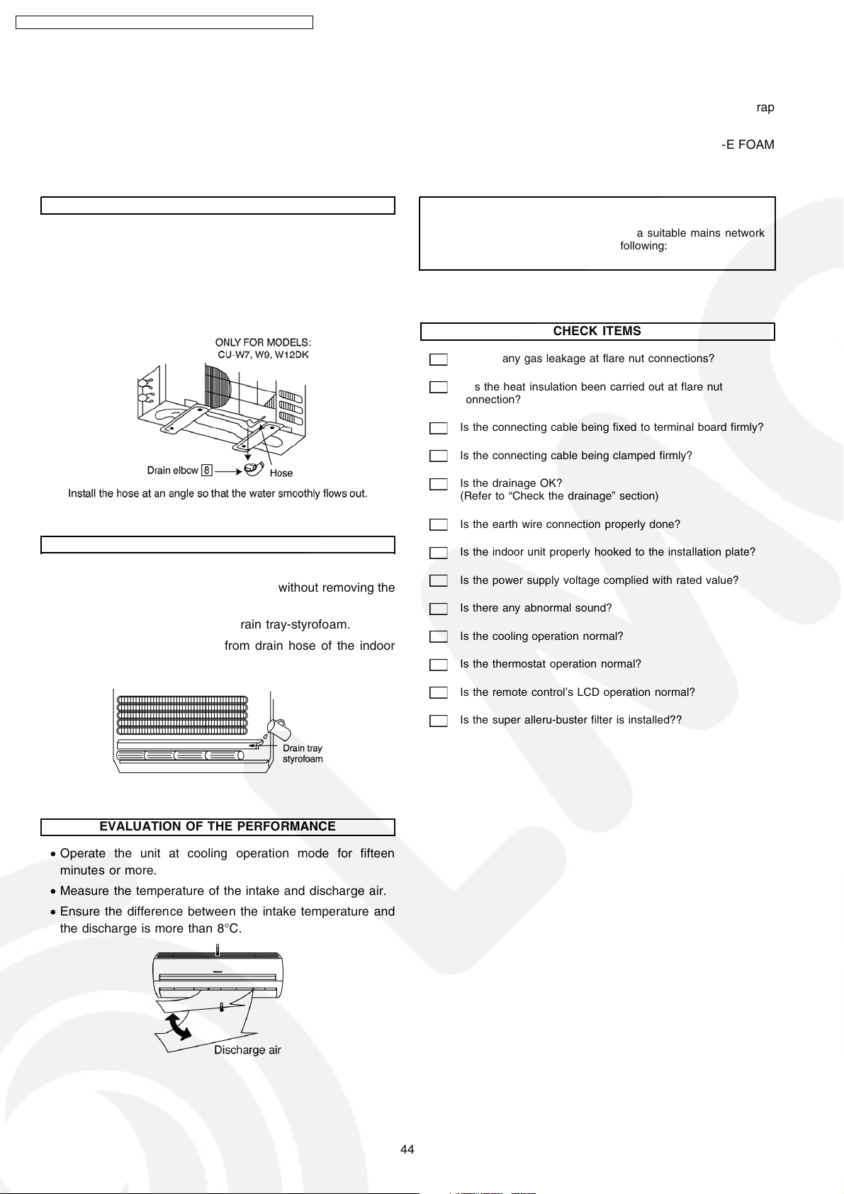
DISPOSAL OF OUTDOOR UNIT DRAIN WATER
• If a drain elbow is used, the unit should be placed on a
stand which is taller than 3 cm.
• If the unit is used in an area where temperature falls below
0°C for 2 or 3 days in succession, it is recommended not to
use a drain elbow, for the drain water freezes and the fan
will not rotate.
NOTE:
These equipment shall be connected to a suitable mains network
with a main impedance less than the following:
CHECK ITEMS
Is there any gas leakage at flare nut connections?
Has the heat insulation been carried out at flare nut
connection?
Is the connecting cable being fixed to terminal board firmly?
CHECK THE DRAINAGE
• Open front panel and remove air filters.
(Drainage checking can be carried out without removing the
front grille.)
• Pour a glass of water into the drain tray-styrofoam.
• Ensure that water flows out from drain hose of the indoor
unit.
EVALUATION OF THE PERFORMANCE
• Operate the unit at cooling operation mode for fifteen
minutes or more.
• Measure the temperature of the intake and discharge air.
• Ensure the differen ce between the intake temperature and
the discharge is more than 8°C.
Is the connecting cable being clamped firmly?
Is the drainage OK?
(Refer to “Check the drainage” section)
Is the earth wire connection properly done?
Is the indoor unit properly hooked to the installation plate?
Is the power supply voltage complied with rated value?
Is there any abnormal sound?
Is the cooling operation normal?
Is the thermostat operation normal?
Is the remote control’s LCD operation normal?
Is the super alleru-buster filter is installed??
44
Page 45

CS-V7DKE CU-V7DKE / CS-V9DKE CU-V9DKE / CS-V12DKE CU-V12DK E
11 Installation And Servicing Air Conditioner Using R410A
11.1. Outline
11.1.1. About R410A Refrigerant
1. Converting air conditioners to R410A
Since it was declared in1974 that chlorofluorocarbons (CFC), hydro chlorofluorocarbons (HCFC) and other substances pose a
destructive danger to the ozone layer in the earth´s upper stratosphere (20 to 40 km above the earth), measures have been
taken around the world to prevent this destruction.
The R22 refrigerant which has conventionally been used in ACs is an HCFC refrigerant and, therefore, possesses this ozone-
destroying potential. International regulations (the Montreal Protocol on Ozone-Damaging Substances) and the domestic laws
of various countries call for the early substitution of R22 by a refrigerant which will not harm the ozone layer.
• In ACs, the HFC refrigerant which has become the mainstream alternative is called R410A.Compared with R22, the
pressure of R410A is approximately 1.6 times as high at the same refrigerant temperature, but the energy efficiency is about
the same. Consisting of hydrogen (H), fluorine (F) and carbon (C), R410A is an HFC refrigerant. Another typical HFC
refrigerant is R407C. While the energy efficiency of R407C is somewhat inferior to that of R410A, it offers the advantage
of having pressure characteristics which are about the same as those of R22, and is used mainly in packaged ACs.
2. The characteristics of HFC (R410A) refrigerants
a. Chemical characteristics
The chemical characteristics of R410A are similar to those of R22 in that both are chemically stable, non-flammable
refrigerants with low toxicity.
However, just like R22, the specific gravity of R410A gas is heavier than that of air. Becaus e of this, it can cause an oxygen
deficiency if it leaks into a closed room since it collects in the lower area of the room. It also generates toxic gas when it is
directly exposed to a flame, so it must be used in a well ventilated environment where it will not collect.
Table 1 Physical comparison of R410A and R22
Composition (wt%) R32/R125 (50/50) R22 (100)
Boiling point (°C) -51.4 -40.8
Vaporizing pressure (25°C) 1.56 Mpa (15.9 kgf/cm2) 0.94 Mpa (9.6 kgf/cm2)
Saturated vapor density 64.0 kg/m
Flammability Non-flammable Non-flammable
Ozone-destroying point (ODP) 0 0.055
Global-warming point (GWP) 1730 1700
R410A R22
3
44.4 kg/m
3
b. Compositional change (pseudo-azeotropic characteristics)
R410A is a pseudo-azeotropic mixture comprising the two components R32 and R125. Multi-component refrigerants with
these chemical characteristics exhibit little compositional change even from phase changes due to vaporization (or
condensation), which means that there is little change in the circulating refrigerant composition even when the refrigerant
leaks from the gaseous section of the piping.
Accordingly, R410A can be handled in almost the same manner as the single-component refrigerant R22. However, when
charging, because there is a slight change in composition between the gas phase and the liquid phase inside a cylinder or
other container, charging should basically begin with the liquid side.
c. Pressure characteristics
As seen in Table 2, the gas pressure of R410A is approximately 1.6 times as high as that of R22 at the same refrigerant
temperature, which means that special R410A tools and materials with high-pressure specifications must be used for all
refrigerant piping work and servicing.
Table 2 Comparison of R410A and R22 saturated vapor density
Refrigerant Temperature (°C) R410A R22
-20 0.30 0.14
0 0.70 0.40
20 1.35 0.81
40 2.32 1.43
60 3.73 2.33
65 4.15 2.60
Unit: MPa
45
Page 46
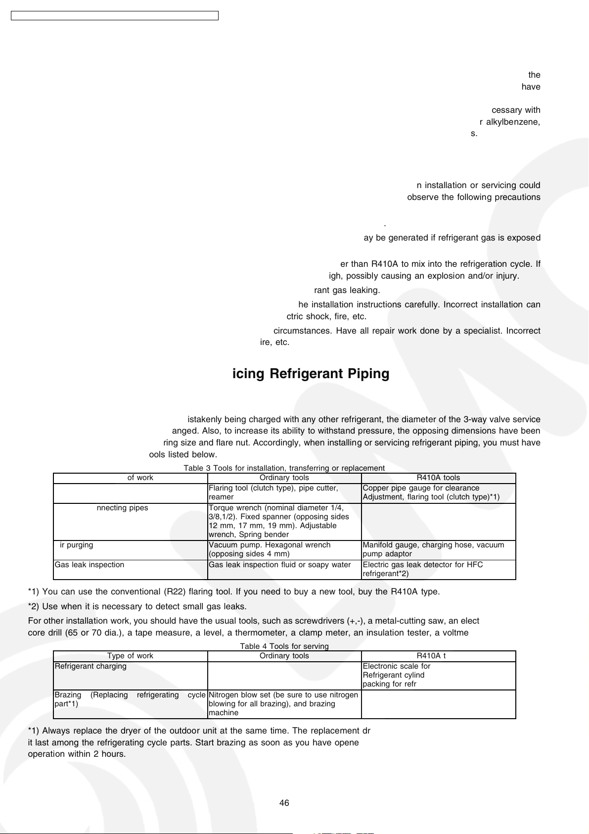
CS-V7DKE CU-V7DKE / CS-V9DKE CU-V9DKE / CS-V12DKE CU-V12DK E
d. R410A refrigerating machine oil
Conventionally, mineral oil or a synthetic oil such as alkylbenzene has been used for R22 refrigerating machine oil. Because
of the poor compatibility between R410A and conventional oils like mineral oil, however, there is a tendency for the
refrigerating machine oil to collect in the refrigerating cycle. For this reason, polyester and other synthetic oils which have
a high compatibility with R410A are used as refrigerating machine oil.
Because of the high hygroscopic property of synthetic oil, more care must be taken in its handlin g than was necessary with
conventional refrigerating machine oils. Also, these synthetic oils will degrade if mixed with mineral oil or alkylbenzene,
causing clogging in capillary tubes or compressor malfunction. Do not mix them under any circumstances.
11.1.2. Safety Measures When Installing/Servicing Refrigerant Piping
Cause the gas pressure of R410A is approximately 1.6 times as high as that of R22, a mistake in installation or servicing could
result in a major accident. It is essential that you use R410A tools and materials, and that you observe the following precautions
to ensure safety.
1. Do not use any refrigerant other than R410A in ACs that have been used with R410A.
2. If any refrigerant gas leaks while you are working, ventilate the room. Toxic gas may be generated if refrigerant gas is exposed
to a direct flame.
3. When installing or transferring an AC, do not allow any air or substance other than R410A to mix into the refrigeration cycle. If
it does, the pressure in the refrigeration cycle can become abnormally high, possibly causing an explosion and/or injury.
4. After finishing the installation, check to make sure there is no refrigerant gas leaking.
5. When installing or transferring an AC, follow the instructions in the installation instructions carefully. Incorrect installation can
result in an abnormal refrigeration cycle or water leakage, electric shock, fire, etc.
6. Do not perform any alterations on the AC unit under any circumstances. Have all repair work done by a specialist. Incorrect
repairs can result in an water leakage, electric shock, fire, etc.
11.2. Tools For Installing/Servicing Refrigerant Piping
11.2.1. Necessary Tools
In order to prevent an R410A AC from mistakenly being charged with any other refrigerant, the diameter of the 3-way valve service
port on the outdoor unit has been changed. Also, to increase its ability to withstand pressure, the opposing dimensions have been
changed for the refrigerant pipe flaring size and flare nut. Accordingly, when installing or servicing refrigerant piping, you must have
both the R410A and ordinary tools listed below.
Type of work Ordinary tools R410A tools
Flaring Flaring tool (clutch type), pipe cutter,
Bending, connecting pipes Torque wrench (nominal diameter 1/4,
Air purging Vacuum pump. Hexagonal wrench
Gas leak inspection Gas leak inspection fluid or soapy water Electric gas leak detector for HFC
*1) You can use the conventional (R22) flaring tool. If you need to buy a new tool, buy the R410A type.
*2) Use when it is necessary to detect small gas leaks.
For other installation work, you should have the usual tools, such as screwdrivers (+,-), a metal-cutting saw, an electrical drill, a hole
core drill (65 or 70 dia.), a tape measure, a level, a thermometer, a clamp meter, an insulation tester, a voltmeter, etc.
Type of work Ordinary tools R410A tools
Refrigerant charging Electronic scale for refrigerant charging.
Brazing (Replacing refrigerating cycle
part*1)
Table 3 Tools for installation, transferring or replacement
reamer
3/8,1/2). Fixed spanner (opposing sides
12 mm, 17 mm, 19 mm). Adjustable
wrench, Spring bender
(opposing sides 4 mm)
Table 4 Tools for serving
Nitrogen blow set (be sure to use nitrogen
blowing for all brazing), and brazing
machine
Copper pipe gauge for clearance
Adjustment, flaring tool (clutch type)*1)
Manifold gauge, charging hose, vacuum
pump adaptor
refrigerant*2)
Refrigerant cylinder. Charging orifice and
packing for refrigerant cylinder
*1) Always replace the dryer of the outdoor unit at the same time. The replacement dryer is wrapped in a vacuum pack. Replace
it last among the refrigerating cycle parts. Start brazing as soon as you have opened the vacuum pack, and begin the vacuuming
operation within 2 hours.
46
Page 47
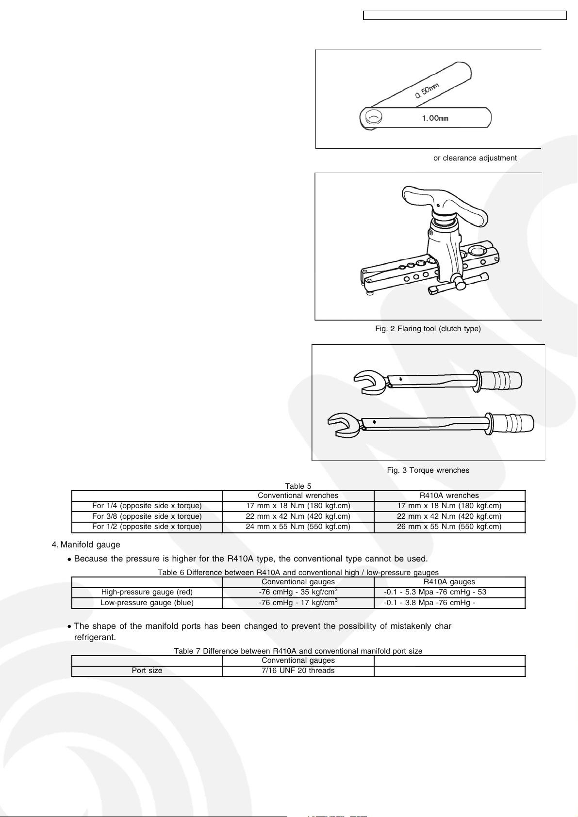
11.2.2. R410A Tools
1. Copper tube gauge for clearance adjustment
(used when flaring with the conventional flaring tool (clutch
type))
• This gauge makes it easy to set the clearance for the
copper tube to 1.0-1.5 mm from the clamp bar of the
flaring tool.
2. Flaring tool (clutch type)
• In the R410A flaring tool, the receiving hole for the
clamp bar is enlarged so the clearance from the clamp
bar can be set to 0-0.5 mm, and the spring inside the
tool is strengthened to increase the strength of the pipeexpanding torque. This flaring tools can also be used
with R22 piping, so we recommend that you select it if
you are buying a new flaring tool.
CS-V7DKE CU-V7DKE / CS-V9DKE CU-V9DKE / CS-V12DKE CU-V12DK E
Fig. 1 Copper tube gauge for clearance adjustment
Fig. 2 Flaring tool (clutch type)
3. Torque wrenches
Fig. 3 Torque wrenches
Table 5
Conventional wrenches R410A wrenches
For 1/4 (opposite side x torque) 17 mm x 18 N.m (180 kgf.cm) 17 mm x 18 N.m (180 kgf.cm)
For 3/8 (opposite side x torque) 22 mm x 42 N.m (420 kgf.cm) 22 mm x 42 N.m (420 kgf.cm)
For 1/2 (opposite side x torque) 24 mm x 55 N.m (550 kgf.cm) 26 mm x 55 N.m (550 kgf.cm)
4. Manifold gauge
• Because the pressure is higher for the R410A type, the conventional type cannot be used.
Table 6 Difference between R410A and conventional high / low-pressure gauges
High-pressure gauge (red) -76 cmHg - 35 kgf/cm
Low-pressure gauge (blue) -76 cmHg - 17 kgf/cm
Conventional gauges R410A gauges
3
3
-0.1 - 5.3 Mpa -76 cmHg - 53 kgf/cm
-0.1 - 3.8 Mpa -76 cmHg - 38 kgf/cm
3
3
• The shape of the manifold ports has been changed to prevent the possibility of mistakenly charging with another type of
refrigerant.
Table 7 Difference between R410A and conventional manifold port size
Port size 7/16 UNF 20 threads 1/2 UNF 20 threads
Conventional gauges R410A gauges
47
Page 48

CS-V7DKE CU-V7DKE / CS-V9DKE CU-V9DKE / CS-V12DKE CU-V12DK E
5. Charging hose
• The pressure resistance of the charging hose has been
raised to match the higher pressure of R410A. The hose
material has also been changed to suit HFC use, and
the size of the fitting has been changed to match the
manifold ports.
Table 8 Difference between R410A and conventional charging hoses
Pressure
resistance
Material NBR rubber HNBR rubber Nylon coating inside
Working pressure 3.4 MPa (35 kgf/cm3) 5.1 MPa (52 kgf/cm3)
Bursting pressure 17.2 MPa (175 kgf/cm3) 27.4 MPa (280 kgf/cm3)
6. Vacuum pump adaptor
• When using a vacuum pump for R410A, it is necessary
to install an electromagnetic valve to prevent the
vacuum pump oil from flowing back into the charging
hose. The vacuum pump adaptor is installed for that
purpose. if the vacuum pump oil (mineral oil) becomes
mixed with R410A, it will damage the unit.
Fig. 4 Manifold gauge charging hose
Conventional hoses R410A hoses
7. Electric gas leak detector for HFC refrigerant
• The leak detector and halide torch that were used with
CFC and HCFC cannot be used with R410A (because
there is no chlorine in the refrigerant).
• The present R134a leak detector can be used, but the
detection sensitivity will be lower (setting the sensitivity
for R134a at 1, the level for R410A will drop to 0.6).
• For detecting small amounts of gas leakage, use the
electric gas leak detector for HFC refrigerant. (Detection
sensitivity with R410A is about 23 g/year).
Fig. 5 Vacuum pump adaptor
Fig. 6 Electric gas leak detector for HFC refrigerant
48
Page 49
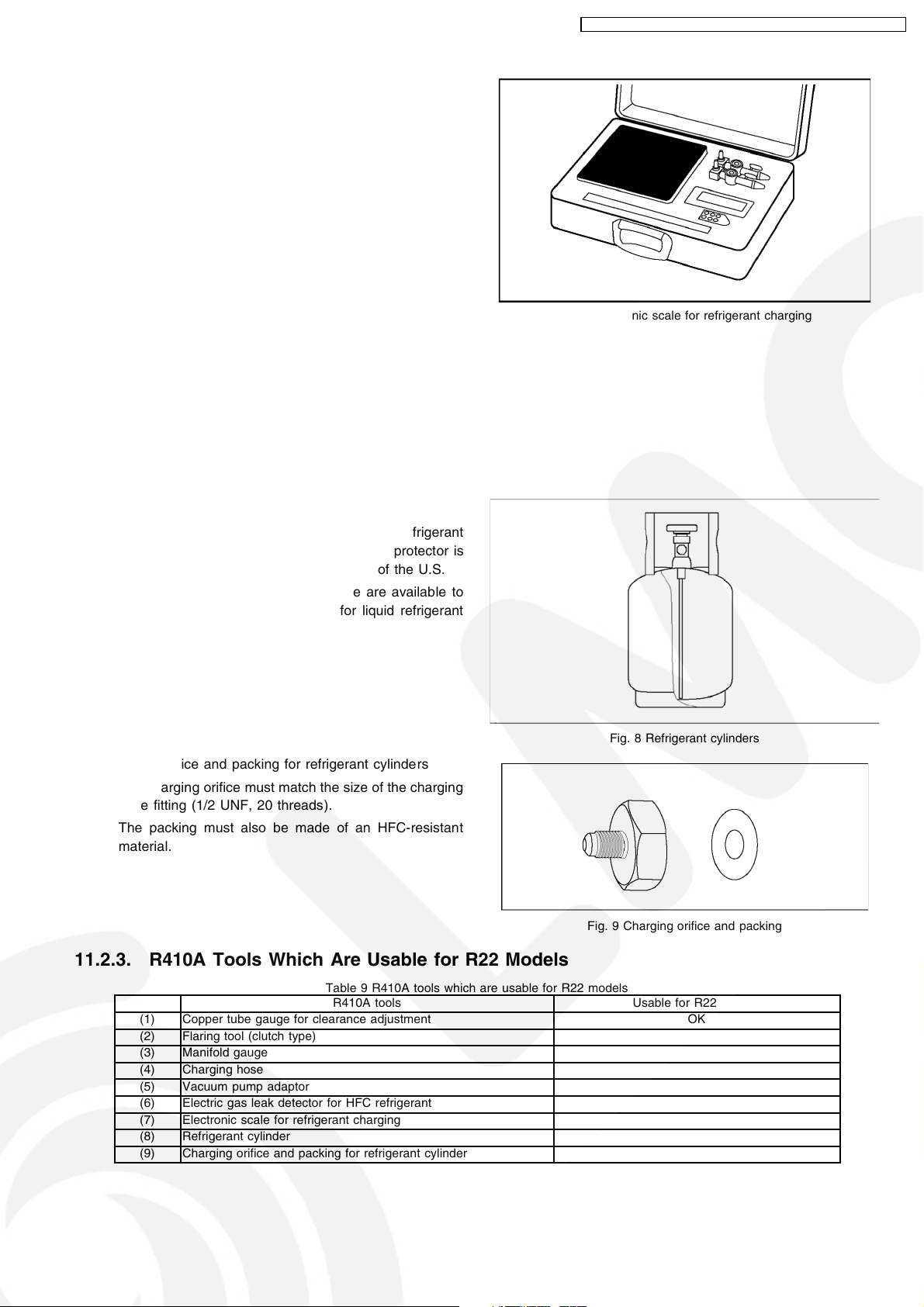
8. Electronic scale for refrigerant charging
• Because of the high pressure and fast vaporizing speed
of R410A, the refrigerant cannot be held in a liquid
phase inside the charging cylinde r when charging is
done using the charging cylinder method, causing
bubbles to form in the measurement scale glass and
making it difficult to see the reading. (Naturally, the
conventional R22 charging cylinde r cannot be used
because of the differences in the pressure resistance,
scale gradation, connecting port size, etc.)
• The electronic scale has been strengthened by using a
structure in which the weight detector for the refrigerant
cylinder is held by four supports. It is also equipped with
two connection ports, one for R22 (7/16 UNF, 20
threads) and one for R410A (1/2 UNF, 20 threads), so
it can also be used for conventional refrigerant charging.
• There are two types of electronic scales, one for 10-kg
cylinders and one for 20-kg cylinders. (The 10-kg
cylinder is recommended.)
Refrigerant charging is done manually by opening and
closing the valve.
CS-V7DKE CU-V7DKE / CS-V9DKE CU-V9DKE / CS-V12DKE CU-V12DK E
Fig. 7 Electronic scale for refrigerant charging
9. Refrigerant cylinders
• The R410A cylinde rs are labeled with the refrigerant
name, and the coating color of the cylinder protector is
pink, which is the color stipulated by ARI of the U.S.
• Cylinders equipped with a siphon tube are available to
allow the cylinder to stand upright for liquid refrigerant
charging.
10. Charging orifice and packing for refrigerant cylinders
• The charging orifice must match the size of the charging
hose fitting (1/2 UNF, 20 threads).
• The packing must also be made of an HFC-resistant
material.
Fig. 8 Refrigerant cylinders
Fig. 9 Charging orifice and packing
11.2.3. R410A Tools Which Are Usable for R22 Models
Table 9 R410A tools which are usable for R22 models
R410A tools Usable for R22 models
(1) Copper tube gauge for clearance adjustment OK
(2) Flaring tool (clutch type) OK
(3) Manifold gauge NG
(4) Charging hose NG
(5) Vacuum pump adaptor OK
(6) Electric gas leak detector for HFC refrigerant NG
(7) Electronic scale for refrigerant charging OK
(8) Refrigerant cylinder NG
(9) Charging orifice and packing for refrigerant cylinder NG
49
Page 50

CS-V7DKE CU-V7DKE / CS-V9DKE CU-V9DKE / CS-V12DKE CU-V12DK E
11.3. Refrigerant Piping Work
11.3.1. Piping Materials
It is recommended that you use copper and copper alloy jointless pipes with a maximum oil adherence of 40 mg/10m. Do not use
pipes that are crushed, deformed, or discolored (especially the inside surface). If these inferior pipes are used, impurities may clog
the expansion valves or capillaries.
Because the pressure of ACs using R410A is higher than those using R22, it is essential that you select materials that are
appropriate for these standards.
The thickness of the copper tubing used for R410A is shown in Table 10. Please be aware that tubing with a thickness of only 0.7
mm is also available on the market, but this should never be used.
Soft pipe Thickness (mm)
Nominal diameter Outside diameter (mm) R410A (Reference) R22
1/4 6.35 0.80 0.80
3/8 9.52 0.80 0.80
1/2 12.7 0.80 0.80
11.3.2. Processing and Connecting Piping Materials
When working with refrigerant piping, the following points must
be carefully observed: no moisture od dust must be allowed to
enter the piping, and there must be no refrigerant leaks.
1. Procedure and precautions for flaring work
a. Cut the pipe
Use a pipe cutter, and cut slowly so the pipe will not be
deformed.
b. Remove burrs and clean shavings from the cut surface
If the shape of the pipe end is poor after removing burrs,
or if shavings adhere to the flared area, it may lead to
refrigerant leaks.
To prevent this, turn the cut surface downward and
remove burrs, then clean the surface, carefully.
c. Insert the flare nut (be sure to use the same nut that is
used on the AC unit)
d. Flaring
Check the clamp bar and the cleanliness of the copper
pipe.
Be sure to use the clamp bar to do the flaring with
accuracy. Use either an R410A flaring tool, or a
conventional flaring tool. flaring tools come in different
sizes, so be sure to check the size before using. When
using a conventional flaring tool, use the copper pipe
gauge for clearance adjustment, etc., to ensure the
correct A dimension (see Fig. 10)
Table 10 Copper tube thickness (mm)
Fig. 10 Flaring dimensions
Fig. 11 Relation between the flare nut structure and flaring tool end
50
Page 51
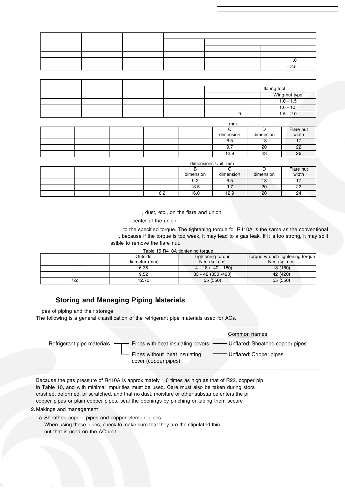
CS-V7DKE CU-V7DKE / CS-V9DKE CU-V9DKE / CS-V12DKE CU-V12DK E
Nominal
diameter
1/4 6.35 0.8 0 - 0.5 1.0 - 1.5 1.5 - 2.0
3/8 9.52 0.8 0 - 0.5 1.0 - 1.5 1.5 - 2.0
1/2 12.70 0.8 0 - 0.5 1.0 - 1.5 2.0 - 2.5
Nominal
diameter
1/4 6.35 0.8 0 - 0.5 0.5 - 1.0 1.0 - 1.5
3/8 9.52 0.8 0 - 0.5 0.5 - 1.0 1.0 - 1.5
1/2 12.70 0.8 0 - 0.5 0.5 - 1.0 1.5 - 2.0
Nominal
diameter
1/4 6.35 0.8 9.1 9.2 6.5 13 17
3/8 9.52 0.8 13.2 13.5 9.7 20 22
1/2 12.70 0.8 16.6 16.0 12.9 23 26
Nominal
diameter
1/4 6.35 0.8 9.0 9.2 6.5 13 17
3/8 9.52 0.8 13.0 13.5 9.7 20 22
1/2 12.70 0.8 16.2 16.0 12.9 20 24
Outside
diameter
(mm)
Outside
diameter
(mm)
Outside
diameter (mm)
Outside
diameter (mm)
Table 13 R410A flare and flare nut dimensions Unit: mm
Wall thickness
(mm)
Table 14 R22 flare and flare nut dimensions Unit: mm
Wall thickness
(mm)
Table 11 R410A flaring dimensions
Wall thickness
(mm)
Table 12 R22 flaring dimensions
Wall thickness
(mm)
A +0, -0.4 B
A +0, -0.4 B
R410A flaring
tool, clutch type
R410A flaring
tool, clutch type
dimension
dimension
A (mm)
Conventional flaring tool
Clutch type Wing-nut type
A (mm)
Conventional flaring tool
Clutch type Wing-nut type
C
dimension
C
dimension
D
dimension
D
dimension
Flare nut
width
Flare nut
width
2. Procedure and precautions for flare connection
a. Check to make sure there is no scratches, dust, etc., on the flare and union.
b. Align the flared surface with the axial center of the union.
c. Use a torque wrench, and tighten to the specified torque. The tightening torque for R410A is the same as the conventional
torque value for R22. Be careful, because if the torque is too weak, it may lead to a gas leak. If it is too strong, it may split
the flare nut or make it impossible to remove the flare nut.
Nominal
diameter
1/4 6.35 14 - 18 (140 - 180) 18 (180)
3/8 9.52 33 - 42 (330 -420) 42 (420)
1/2 12.70 55 (550) 55 (550)
Table 15 R410A tightening torque
Outside
diameter (mm)
Tightening torque
N.m (kgf.cm)
Torque wrench tightening torque
N.m (kgf.cm)
11.3.3. Storing and Managing Piping Materials
1. Types of piping and their storage
The following is a general classification of the refrigerant pipe materials used for ACs.
Because the gas pressure of R410A is approximately 1.6 times as high as that of R22, copper pipes with the thickness shown
in Table 10, and with minimal impurities must be used. Care must also be taken during storage to ensure that pipes are not
crushed, deformed, or scratched, and that no dust, moisture or other substance enters the pipe interior. When storing sheathed
copper pipes or plain copper pipes, seal the openings by pinching or taping them securely.
2. Makings and management
a. Sheathed copper pipes and copper-element pipes
When using these pipes, check to make sure that they are the stipulated thickness. For flare nuts, be sure to used the same
nut that is used on the AC unit.
51
Page 52

CS-V7DKE CU-V7DKE / CS-V9DKE CU-V9DKE / CS-V12DKE CU-V12DK E
b. Copper pipes
Use only copper pipes with the thickness given in table 10, and with minimal impurities. Because the surface of the pipe is
exposed, you should take special care, and also take measures such as marking the pipes to make sure they are easily
distinguished from other piping materials, to prevent mistaken use.
3. Precautions during refrigerant piping work
Take the following precautions on-site when connecting pipes. (Keep in mind that the need to control the entry of moisture and
dust is even more important that in conventional piping).
a. Keep the open ends of all pipes sealed until connection with AC equipment is complete.
b. Take special care when doing piping work on rainy days. The entering of moisture will degrade the refrigerating machine oil,
and lead to malfunctions in the equipment.
c. Complete all pipe connections in as short a time as possible. If the pipe must be left standing for a long time after removing
the seal, it must be thoroughly purged with nitrogen, or dried with a vacuum pump.
11.4. Installation, Transferring, Servicing
11.4.1. Inspecting Gas Leaks with a Vacuum Pump for New Installations (Using New
Refrigerant Piping)
1. From the viewpoint of protecting the global environment, please do not release refrigerant into the atmosphere.
a. Connect the projecting side (pin-pushing side) of the charging hose for the manifold gauge to the service port of the 3-way
valve. (1)
b. Fully open the handle Lo of the manifold gauge and run the vacuum pump. (2) (If the needle of the low-pressure gauge
instantly reaches vacuum, re-check step a).)
c. Continue the vacuum process for at least 15 minutes, then check to make sure the low-pressure gauge has reached -0.1
MPa (-76 cmHg). Once the vacuum process has finished, fully close the handle Lo of the manifold gauge and stop the
vacuum pump operation, then remove the charging hose that is connected to the vacuum pump adaptor. (Leave the unit in
that conditio n for 1-2 minutes, and make sure that the needle of the manifold gauge does not return.) (2) and (3)
d. Turn the valve stem of the 2-way valve 90° counter-clockwise to open it, then, after 10 seconds, close it and inspect for a
gas leak (4)
e. Remove the charging hose from the 3-way valve service port, then open both the 2-way valve and 3-way valve. (1) (4) (Turn
the valve stem in the counter-clockwise direction until it gently makes contact. Do not turn it forcefully).
f. Tighten the service port cap with a torque wrench (18 N.m (1.8 kgf.m)). (5) Then tighten the 2-way valve and 3-way valve
caps with a torque wrench (42 N.m (4.2 kgf.m)) or (55 N.m (5.5 kgf.m)). (6)
g. After attaching each of the caps, inspect for a gas leak around the cap area. (5) (6)
Precautions
• Be sure to read the instructions for the vacuum pump,
vacuum pump adaptor and manifold gauge prior to use,
and follow the instructions carefully.
• Make sure that the vacuum pump is filled with oil up to
the designated line on the oil gauge.
• The gas pressure back flow prevention valve on the
charging hose is generally open during use. When you
are removing the charging hose from the service port, it
will come off more easily if you close this valve.
Fig. 12 Vacuum pump air purging configuration
52
Page 53
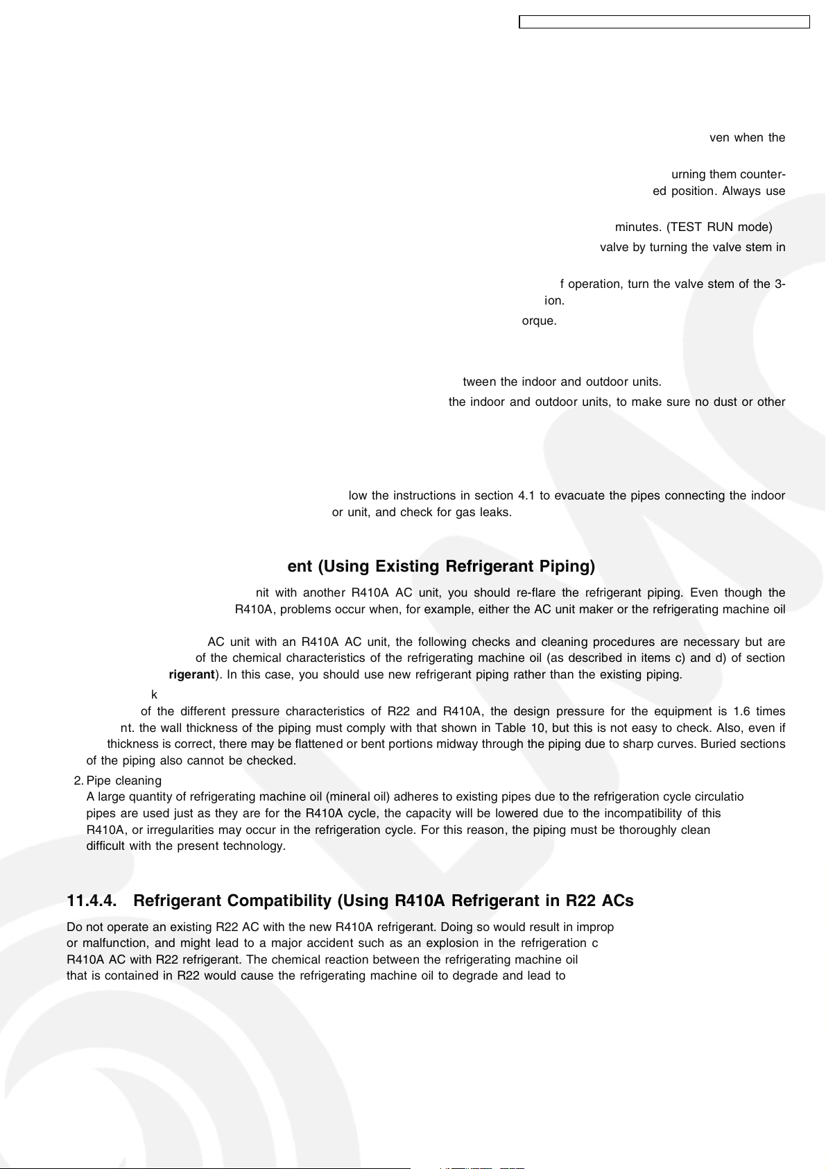
CS-V7DKE CU-V7DKE / CS-V9DKE CU-V9DKE / CS-V12DKE CU-V12DK E
11.4.2. Transferring (Using New Refrigerant Piping)
1. Removing the unit
a. Collecting the refrigerant into the outdoor unit by pumping down
The refrigerant can be collected into the outdoor unit (pumping down) by pressing the TEST RUN button, even when the
temperature of the room is low.
• Check to make sure that the valve stems of the 2-way valve and 3-way valve have been opened by turning them counter-
clockwise. (Remove the valve stem caps and check to see that the valve stems are fully opened position. Always use
a hex wrench (with 4-mm opposing sides) to operate the valve stems.)
• Press the TEST RUN button on the indoor unit, and allow preliminary operation for 5-6 minutes. (TEST RUN mode)
• After stopping the operation, let the unit sit for about 3 minutes, then close the 2-way valve by turning the valve stem in
the clockwise direction.
• Press the TEST RUN button on the indoor unit again, and after 2-3 minutes of operation, turn the valve stem of the 3-
way valve quickly in the clockwise direction to close it, then stop the operation.
• Tighten the caps of the 2-way valve and 3-way valve to the stipulated torque.
• Remove the connection pipes (liquid side and gas side).
b. Removing the indoor and outdoor units.
• Disconnect the pipes and connecting electric cables from between the indoor and outdoor units.
• Put capped flare nuts onto all of the pipe connections of the indoor and outdoor units, to make sure no dust or other
foreign matter enters.
• Remove the indoor and outdoor units.
2. Installing the unit
Install the unit using new refrigerant piping. Follow the instructions in section 4.1 to evacuate the pipes connecting the indoor
and outdoor units, and the pipes of the indoor unit, and check for gas leaks.
11.4.3. AC Units Replacement (Using Existing Refrigerant Piping)
When replacing an R410A AC unit with another R410A AC unit, you should re-flare the refrigerant piping. Even though the
replacement AC unit uses the R410A, problems occur when, for example, either the AC unit maker or the refrigerating machine oil
is differen t.
When replacing an R22 AC unit with an R410A AC unit, the following checks and cleaning procedures are necessary but are
difficult to do because of the chemical characteristics of the refrigerating machine oil (as described in items c) and d) of section
About R410A Refrigerant
1. Piping check
Because of the different pressure characteristics of R22 and R410A, the design pressure for the equipment is 1.6 times
different. the wall thickness of the piping must comply with that shown in Table 10, but this is not easy to check. Also, even if
the thickness is correct, there may be flattened or bent portions midway through the piping due to sharp curves. Buried sections
of the piping also cannot be checked.
2. Pipe cleaning
A large quantity of refrigerating machine oil (mineral oil) adheres to existing pipes due to the refrigeration cycle circulation. If the
pipes are used just as they are for the R410A cycle, the capacity will be lowered due to the incompatibility of this oil with the
R410A, or irregularities may occur in the refrigeration cycle. For this reason, the piping must be thoroughly cleaned , but this is
difficult with the present technology.
). In this case, you should use new refrigerant piping rather than the existing piping.
11.4.4. Refrigerant Compatibility (Using R410A Refrigerant in R22 ACs and Vice Versa)
Do not operate an existing R22 AC with the new R410A refrigerant. Doing so would result in improper functioning of the equipment
or malfunction, and might lead to a major accident such as an explosion in the refrigeration cycle. Similarly, do not operate an
R410A AC with R22 refrigerant. The chemical reaction between the refrigerating machine oil used in R410A ACs and the chlorine
that is contained in R22 would cause the refrigerating machine oil to degrade and lead to malfunction.
53
Page 54

CS-V7DKE CU-V7DKE / CS-V9DKE CU-V9DKE / CS-V12DKE CU-V12DK E
11.4.5. Recharging Refrigerant During Servicing
When recharging is necessary, insert the specified amount of new refrigerant in accordance with the followin g procedure.
1. Connect the charging hose to the service port of the outdoor unit.
2. Connect the charging hose to the vacuum pump adaptor. At this time, fully open the 2-way valve and 3-way valve.
3. Fully open the handle Lo of the manifold gauge, turn on the power of the vacuum pump and continue the vacuum process for
at least one hour.
4. Confirm that the low pressure gauge shows a reading of -0.1 Mpa (-76 cmHg), then fully close the handle Lo, and turn off the
vacuum pump. Wait for 1-2 minutes, then check to make sure that the needle of the Low pressure gauge has not returned. See
Fig. 13 for the remaining steps of this procedure.
5. Set the refrigerant cylinder onto the electronic scale, then connect the hose the cylinder and to the connection port for the
electronic scale. (1)(2)
Precaution:
Be sure to set up the cylinder for liquid charging. If you use a cylinder equipped with a siphon tube, you can charge the liquid
without having to turn the cylinder around
6. Remove the charging hose of the manifold gauge from the vacuum pump adaptor, and connect it to the connection port of the
electronic scale. (2)(3)
7. Open the valve of the refrigerant cylinder, then open the charging valve slightly and close it. Next, press the check valve of the
manifold gauge and purge the air. (2)(4) (Watch the liquid refrigerant closely at this point.)
8. After adjusting the electronic scale to zero, open the charging valve, then open the valve Lo of the manifold gauge and charge
with the liquid refrigerant. (2)(5) (Be sure to read the operating instructions for the electronic scale.)
9. If you cannot charge the stipulated amount, operate the unit in the cooling mode while charging a little of the liquid at a time
(about 150 g/time as a guideline). If the charging amount is insufficient from one operation, wait about one minute, then use the
same procedure to do the liquid charging again.
Precaution:
Never use the gas side to allow a larger amount of liquid refrigerant to be charged while operating the unit.
10. Close the charging valve, and after charging the liquid refrigerant inside the charging hose, fully close the valve Lo of the
manifold gauge, and stop the operation of the unit. (2)(5)
11. Quickly remove the charging hose from the service port. (6) If you stop midway through, the refrigerant that is in the cycle will
be discharged.
12. After putting on the caps for the service port and operating valve, inspect around the caps for a gas leak. (6)(7)
Fig. 13 Re-charging refrigerant
54
Page 55

CS-V7DKE CU-V7DKE / CS-V9DKE CU-V9DKE / CS-V12DKE CU-V12DK E
11.4.6. Brazing
As brazing requires sophisticated techniques and experiences, it must be performed by a qualified person.
In order to prevent the oxide film from occurring in the pipe interior during brazing, it is effective to proceed with brazing while letting
dry nitrogen gas (N
<Brazing Method for Preventing Oxidation>
1. Attach a reducing valve to the nitrogen gas cylinder.
2. Apply a seal onto the clearance between the piping and inserted pipe for the nitrogen gas in order to prevent the nitrogen gas
from flowing backward.
3. When the nitrogen gas is flowing, be sure to keep the piping end open.
4. Adjust the flow rate of nitrogen gas so that it is lower than 0.05 m
5. After taking the steps above, keep the nitrogen gas flowing until the piping cools down to a certain extent (i.e. temperature at
which pipes are touchable with finger).
6. Completely remove the flux after brazing.
) flow.
2
3
/h, or 0.02 MPa (0.2 kgf/cm2) by means of the reducing valve.
Fig. 14 Prevention of Oxidation during Brazing
Cautions during brazing
1. General Cautions
a. The brazing strength should be high as required.
b. After operation, airtightness should be kept under pressurized condition.
c. During brazing do not allow component materials to become damaged due to overheating.
d. The refrigerant pipe work should not become blocked with scale or flux.
e. The brazed part should not restrict the flow in the refrigerant circuit.
f. No corrosion should occur from the brazed part.
2. Prevention of Overheating
Due to heating, the interior and exterior surfaces of treated metal may oxidize. Especially, when the interior of the refrigerant
circuit oxidizes due to overheating, scale occurs and stays in the circuit as dust, thus exerting a fatally adverse effect. So,
make brazing at adequate brazing temperature and with minimum of heating area.
3. Overheating Protection
In order to prevent components near the brazed part from overheating damage or quality deterioration due to flame or heat,
take adequate steps for protection such as (1) by shielding with a metal plate, (2) by using a wet cloth, and (3) by means
of heat absorbent.
4. Movement during Brazing
Eliminate all vibration during brazing to protect brazed joints from cracking and breakage.
5. Oxidation Preventative
In order to improve the brazing efficiency, various types of antioxidant are available on the market. However, the
constituents of these are widely varied, and some are anticipated to corrode the piping materials, or adversely affect HFC
refrigerant, lubricating oil, etc. Exercise care when using an oxidation preventive.
11.4.7. Servicing Tips
The drier must also be replaced whenever replacing the refrigerant cycle parts. Replacing the refrigerant cycle parts first
before replacing the drier. The drier is supplied in a vacuum pack. Perform brazing immediately after opening the vacuum
pack, and then start the vacuum within two hours. In addition, the drier also needs to be replaced when the refrigerant has
leaked completely. (Applicable for drier models only)
55
Page 56

CS-V7DKE CU-V7DKE / CS-V9DKE CU-V9DKE / CS-V12DKE CU-V12DK E
12 Servicing Information
12.1. Distinction Of Lead Free (PbF) Printed Circuit Board
• Printed circuit boards (manufactured) using lead free solder will have a PbF stamp on the Printed Circuit board.
CAUTION
• Pb free solder has a higher melting point than standard solder; typically the melting point is 50 - 70°F(30-40°C) higher.
Please use a high temperature solder iron and set it to 700 ± 20°F (370 ± 10°C).
• Pb free solder will tend to splash when heated too high (about 1100°F/600°C).
• If you must use Pb solder, please completely remove all of the Pb free solder on the pin or solder area before applyin g Pb
solder. If this is not practical, be sure to heat the Pb free solder until it melts, before applying Pb solder.
12.2. Indoor Electronic Controllers Removal Procedures
• Electronic controller and Display Complete unit can be seen
by following the below removal procedures.
Fig. 1
− Remove the 2 caps and 2 screws at the bottom of the
Front Grille. (Fig. 1)
Fig. 2
− Remove the Front Grille Complete. (Fig. 2)
Fig. 3
− Release the taps on top and on the right side of metal
plate cover. (Fig. 3)
− Then remove the metal plate cover. (Fig. 3)
− Remove the indicator complete screw, and then remove
the indicator complete. (Fig. 3)
56
Page 57

CS-V7DKE CU-V7DKE / CS-V9DKE CU-V9DKE / CS-V12DKE CU-V12DK E
Fig. 4
−
To remove the electronic controller.
−
Release CN-FM connectors. (Fig. 4)
−
Release CN-Sonic connector. (Fig. 4)
−
Release CN-FB connector. (Fig. 4)
−
Release CN-ION connector. (Fig. 4)
−
Release CN-TH connector. (Fig. 4)
−
Release CN-STM connector. (Fig. 4)
−
Release CN-REC/DISP connector. (Fig. 4)
−
Press the hook to the right then take out the PCB. (Fig.
5)
−
Release Ry-Pwr connector (black and brown) and Ac-
Wht connector from the PCB. (Fig. 5)
Fig. 5
12.3. Indoor Fan Motor And Cross Flow Fan Removal Procedures
•
Remove Control Board Cover
Fig. 6
−
Remove the screw on the left of the unit. (Fig. 6)
−
Pull the hook to the left and lift up the evaporator.
(Fig. 6)
−
Pull down the Discharge Grille Complete. (Fig. 6)
57
Fig. 7
Fig. 8
−
Remove indoor pipe sensor and air intake sensor from
the evaporator. (Fig. 7)
−
Remove the earth wire from the evaporator. (Fig. 7)
Page 58

CS-V7DKE CU-V7DKE / CS-V9DKE CU-V9DKE / CS-V12DKE CU-V12DK E
− Release the generator complete wire (green and red).
(Fig. 8)
− Remove 2 screws on the right and 1 screw at the left
side of the control board. (Fig. 7)
− Press down the hook on the left side of control board.
(Fig. 7)
− Then pull out the Control Board Complete from the unit.
(Fig. 7)
Fig. 10
− Push up the evaporator and remove cross flow fan by
pulling both cross flow fan and fan motor. (Fig. 10)
Fig. 9
− Remove the cross flow fan bushing from the chassis.
(Fig. 9)
− Loosen the fan boss screw at the cross flow fan. (Fig. 9)
12.4. Remote Control Reset
• When the batteries are inserted for the first time or the
batteries are replaced, you may notice the indications at
remote control’s display screen blink continuously and not
functionable. If this condition happens, try to reset the
remote control by pushing the reset terminal with a pointing
device.
• You may also do the reset to erase the setting at remote
control and restore back the default setting.
58
Page 59
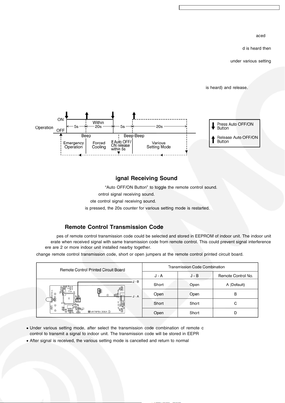
CS-V7DKE CU-V7DKE / CS-V9DKE CU-V9DKE / CS-V12DKE CU-V12DK E
12.5. Auto OFF/ON Button
• The “Auto OFF/ON Button” (behind the front grille) is used to operate the air conditioner if remote control is misplaced or
mulfunctioning.
• Forced cooling operation is possible by pressing the “Auto OFF/ON Button” for more than 5s where “beep” sound is heard then
release the button.
• User able to select remote control transmission code and toggle remote control signal receiving sound under various setting
mode.
• To enter various setting mode:
− Press the “Auto OFF/ON Button” continuously for 5s (“beep” sound is heard) and release.
− Within 20s, press the “Auto OFF/ON Button” continuously for 5s again (2 “beep” sound is heard) and release.
− Various setting mode has limit up to 20s. Then return to normal operation.
12.5.1. Toggle Remote Control Signal Receiving Sound
• Under various setting mode, press the “Auto OFF/ON Button” to toggle the remote control sound.
− Short “beep”: Turn ON remote control signal receiving sound.
− Long “beep”: Turn OFF remote control signal receiving sound.
• After “Auto OFF/ON Button” is pressed, the 20s counter for various setting mode is restarted.
12.5.2. Select Remote Control Transmission Code
• There are 4 types of remote control transmission code could be selected and stored in EEPROM of indoor unit. The indoor unit
will only operate when received signal with same transmission code from remote control. This could prevent signal interference
when there are 2 or more indoor unit installed nearby together.
• To change remote control transmission code, short or open jumpers at the remote control printed circuit board.
• Under various setting mode, after select the transmission code combination of remote control, press any button of remote
control to transmit a signal to indoor unit. The transmission code will be stored in EEPROM.
• After signal is received, the various setting mode is cancelled and return to normal operation.
59
Page 60
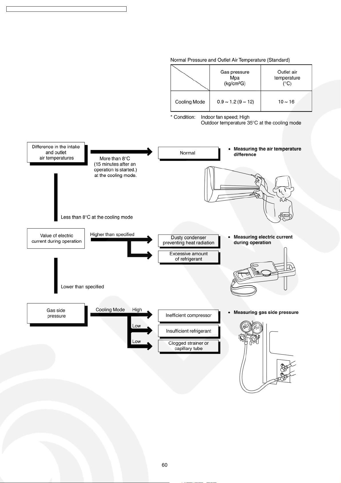
CS-V7DKE CU-V7DKE / CS-V9DKE CU-V9DKE / CS-V12DKE CU-V12DK E
13 Troubleshooting Guide
13.1. Refrigeration Cycle System
In order to diagnose malfunctions, make sure that there are no
electrical problems before inspecting the refrigeration cycle.
Such problems include insufficient insulation, problem with the
power source, malfunction of a compressor and a fan.
The normal outlet air temperature and pressure of the
refrigeration cycle depends on various conditions, the standard
values for them are shown in the table to the right.
60
Page 61
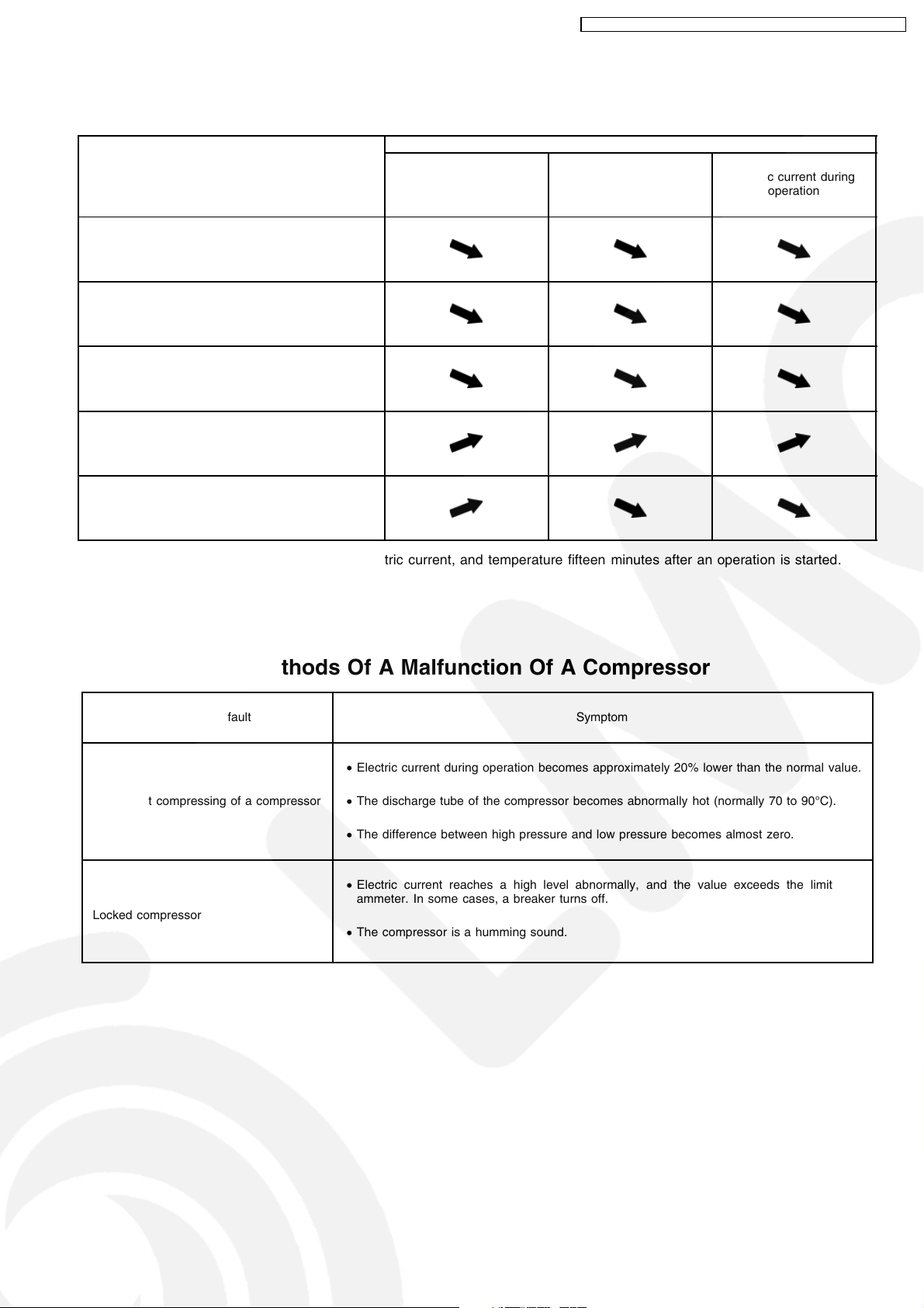
CS-V7DKE CU-V7DKE / CS-V9DKE CU-V9DKE / CS-V12DKE CU-V12DK E
13.2. Relationship Between The Condition Of The Air Conditioner And
Pressure And Electric Current
Cooling Mode
Condition of the air
conditoner Low Pressure High Pressure Electric current during
Insufficient refrigerant (gas leakage)
Clogged capillary tube or Strainer
Short circuit in the indoor unit
Heat radiation deficiency of the outdoor unit
operation
Inefficient compression
•
Carry out the measurements of pressure, electric current, and temperature fifteen minutes after an operation is started.
13.3. Diagnosis Methods Of A Malfunction Of A Compressor
Nature of fault Symptom
•
Electric current during operation becomes approximately 20% lower than the normal value.
Insufficient compressing of a compressor
Locked compressor
•
The discharge tube of the compressor becomes abnormally hot (normally 70 to 90°C).
•
The difference between high pressure and low pressure becomes almost zero.
•
Electric current reaches a high level abnormally, and the value exceeds the limit of an
ammeter. In some cases, a breaker turns off.
•
The compressor is a humming sound.
61
Page 62

CS-V7DKE CU-V7DKE / CS-V9DKE CU-V9DKE / CS-V12DKE CU-V12DK E
14 Technical Data
14.1. Thermostat Characteristics
14.1.1. CS-V7DKE CS-V9DKE CS-V12DKE
14.2. Sensible Capacity Chart
14.2.1.
14.2.2.
14.2.3.
●
CS-V7DKE
230V Outdoor Temp. (°C)
Indoor wet
bulb temp.
17.0°C 2.38 1.80 0.68 2.22 1.73 0.73 2.07 1.66 0.78 1.88 1.58 0.84
19.0°C 2.40 0.74
19.5°C 2.61 1.89 0.69 2.44 1.82 0.74 2.27 1.75 0.79 2.07 1.66 0.86
22.0°C 2.85 1.96 0.70 2.66 1.88 0.76 2.48 1.82 0.81 2.25 1.73 0.87
●
CS-V9DKE
230V Outdoor Temp. (°C)
Indoor wet
bulb temp.
17.0°C 2.98 2.26 0.86 2.78 2.16 0.93 2.59 2.08 0.99 2.35 1.98 1.07
19.0°C 3.00 0.94
19.5°C 3.27 2.36 0.88 3.05 2.27 0.94 2.84 2.18 1.01 2.58 2.08 1.09
22.0°C 3.56 2.45 0.89 3.33 2.36 0.96 3.10 2.27 1.03 2.81 2.17 1.11
●
CS-V12DKE
230V Outdoor Temp. (°C)
Indoor wet
bulb temp.
17.0°C 3.65 2.77 1.04 3.41 2.65 1.12 3.17 2.55 1.20 2.89 2.42 1.30
19.0°C 3.68 1.14
19.5°C 4.01 2.90 1.06 3.75 2.78 1.14 3.48 2.68 1.22 3.17 2.55 1.32
22.0°C 4.37 3.01 1.08 4.08 2.89 1.17 3.80 2.79 1.25 3.45 2.66 1.34
TC SHC IP TC SHC IP TC SHC IP TC SHC IP
TC SHC IP TC SHC IP TC SHC IP TC SHC IP
TC SHC IP TC SHC IP TC SHC IP TC SHC IP
30 35 40 46
30 35 40 46
30 35 40 46
TC - Total Cooling Capacity (kW) Indoor 27°C/19°C
SHC - Sensible Heat Capacity (kW) Outdoor 35°C/24°C
IP - Input Power (kW)
62
Page 63
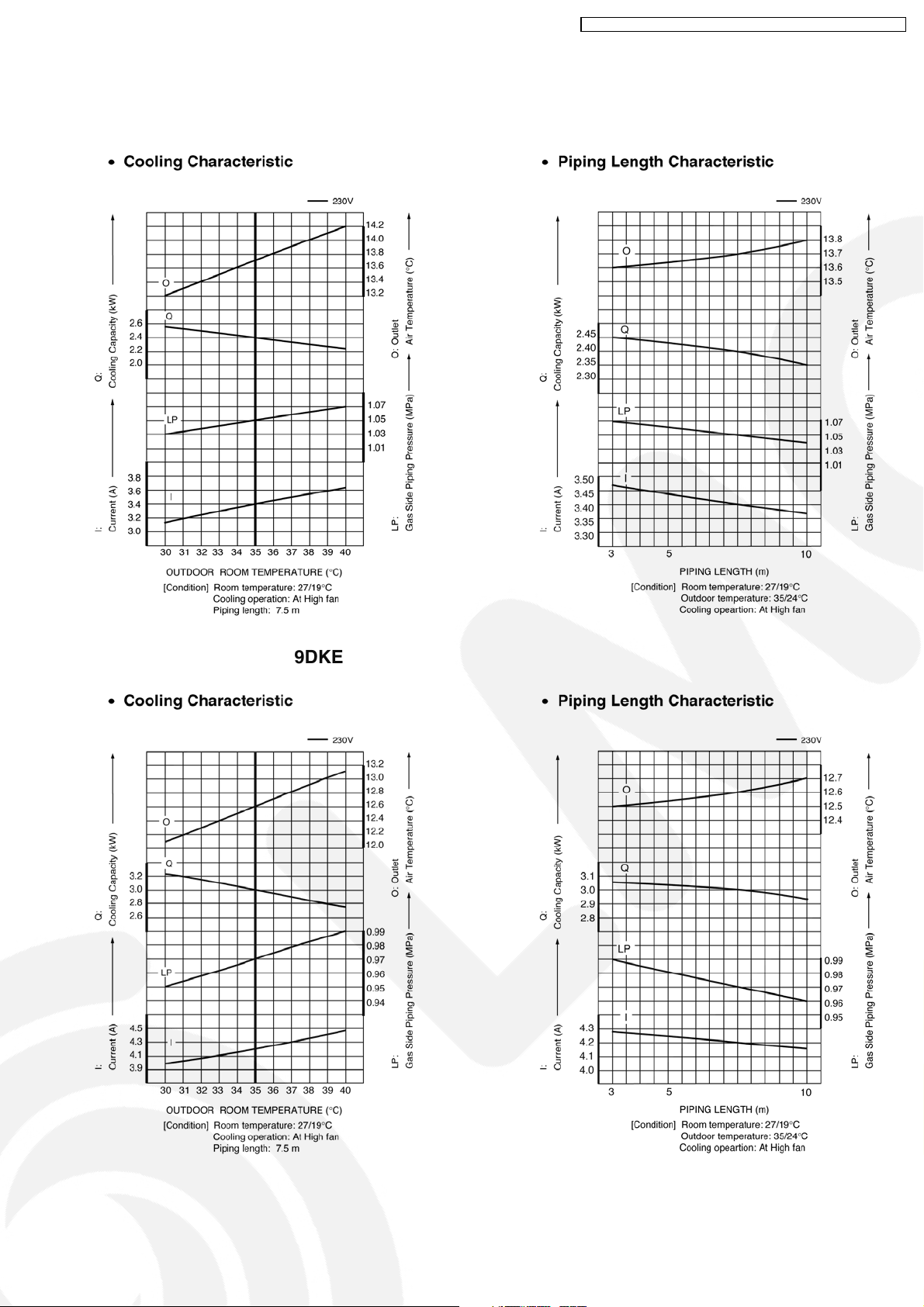
14.3. Operation Characteristics
14.3.1. CS-V7DKE CU-V7DKE
CS-V7DKE CU-V7DKE / CS-V9DKE CU-V9DKE / CS-V12DKE CU-V12DK E
14.3.2. CS-V9DKE CU-V9DKE
63
Page 64

CS-V7DKE CU-V7DKE / CS-V9DKE CU-V9DKE / CS-V12DKE CU-V12DK E
14.3.3. CS-V12DKE CU-V12DKE
64
Page 65
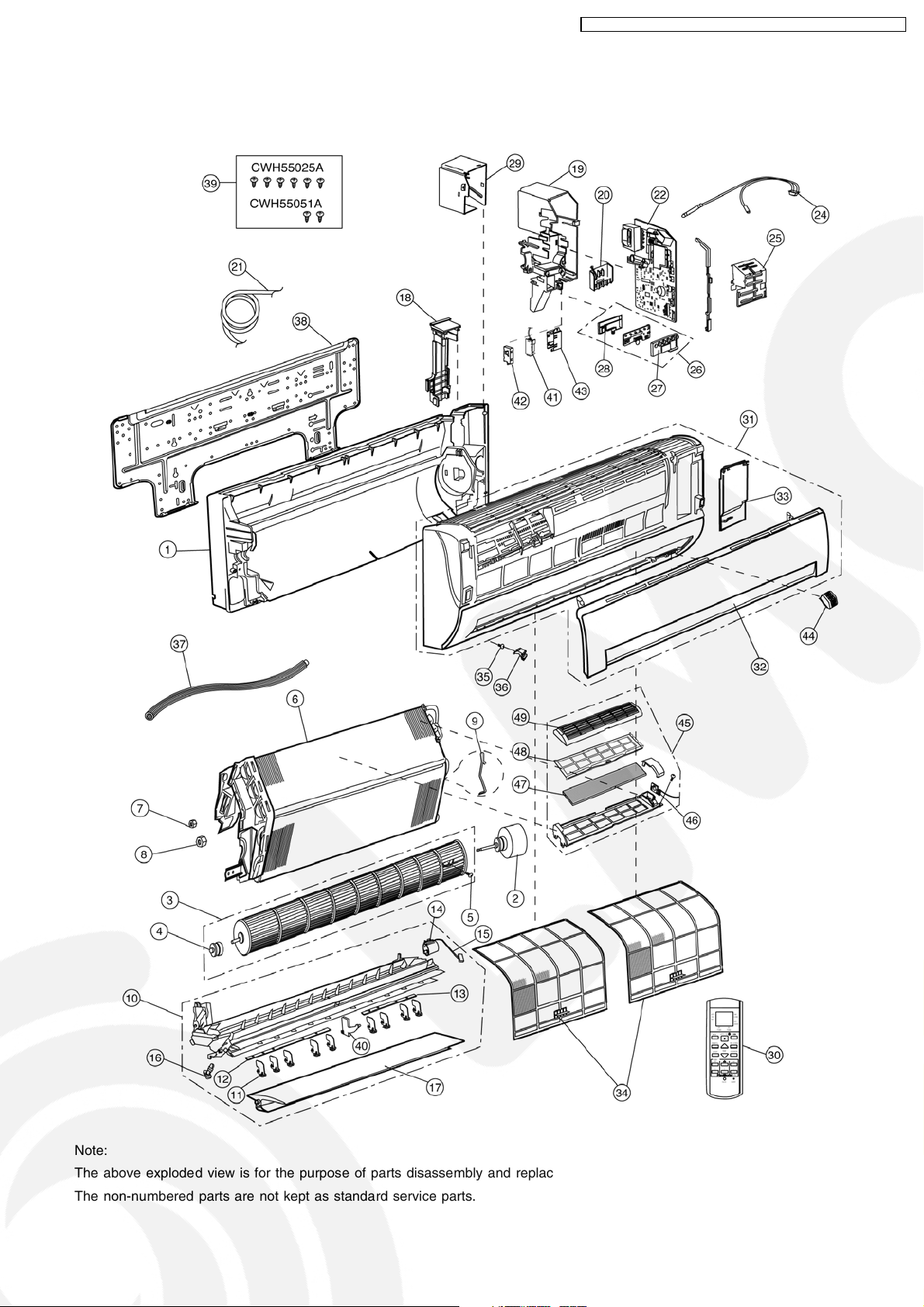
15 Exploded View (Indoor Unit)
15.1. CS-V7DKE CS-V9DKE CS-V12DKE
CS-V7DKE CU-V7DKE / CS-V9DKE CU-V9DKE / CS-V12DKE CU-V12DK E
Note:
The above exploded view is for the purpose of parts disassembly and replacement.
The non-numbered parts are not kept as standard service parts.
65
Page 66
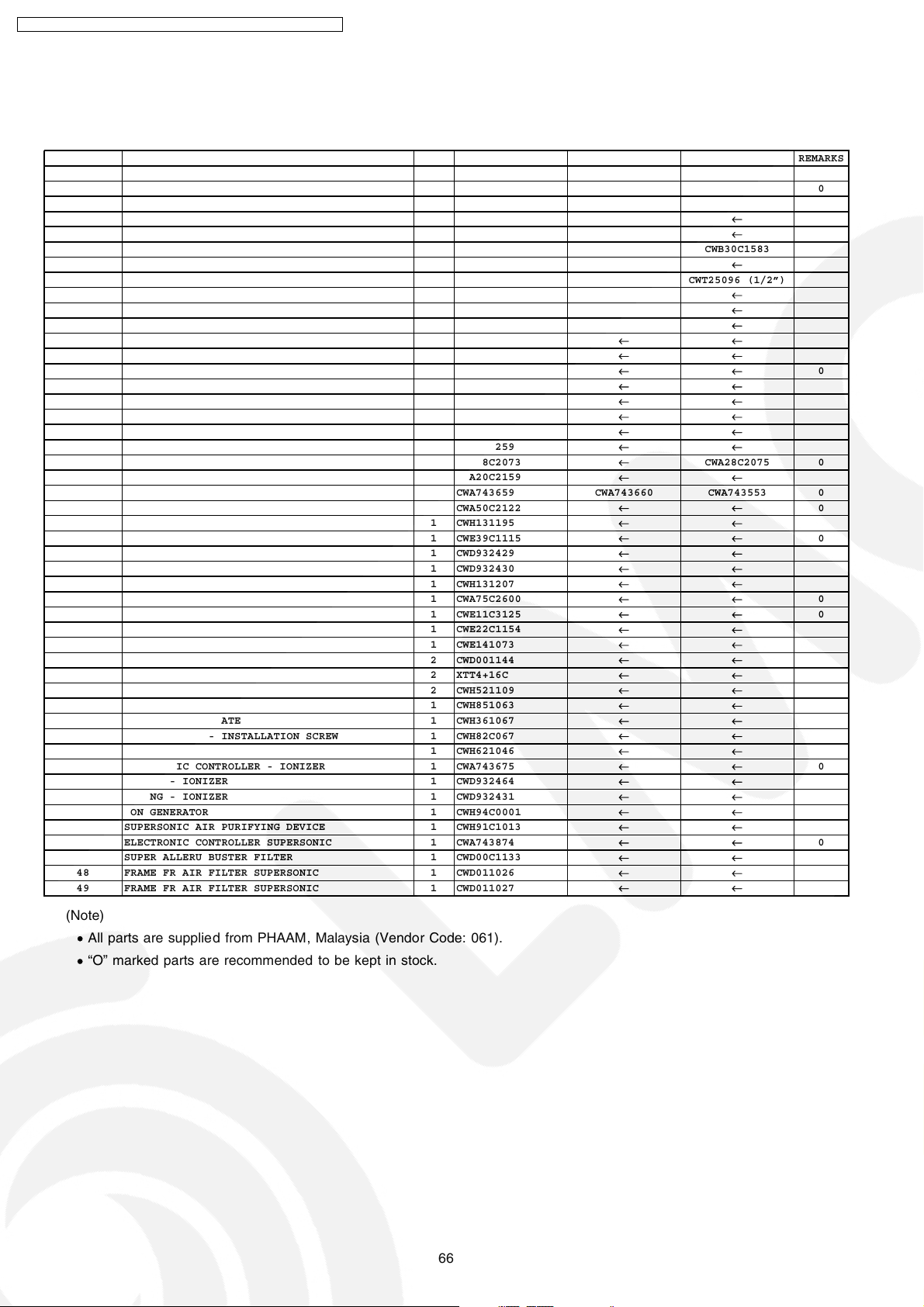
CS-V7DKE CU-V7DKE / CS-V9DKE CU-V9DKE / CS-V12DKE CU-V12DK E
16 Replacement Parts List (Indoor Unit)
16.1. CS-V7DKE CS-V9DKE CS-V12DKE
REF. NO. PART NAME & DESCRIPTION QTY. CS-V7DKE CS-V9DKE CS-V12DKE REMARKS
1 CHASSY COMPLETE 1 CWD50C1377
2 FAN MOTOR 1 CWA921181
3 CROSS FLOW FAN COMPLETE 1 CWH02C1031
4 BEARING ASS’Y 1 CWH64K007
5 SCREW - CROSS FLOW FAN 1 CWH4580304
6 EVAPORATOR 1 CWB30C1599
7 FLARE NUT 1 CWT25086(1/4”)
8 FLARE NUT 1 CWT25087 (3/8”)
9 HOLDER SENSOR 1 CWH32143
10 DISCHARGE GRILLE COMPLETE 1 CWE20C2366
11 VERTICAL VANE 9 CWE241150
12 CONNECTING BAR 1 CWE261066
13 CONNECTING BAR 1 CWE261070
14 AIR SWING MOTOR 1 CWA98260
15 LEAD WIRE - AIR SWING MOTOR 1 CWA67C3977
16 CAP - DRAIN TRAY 1 CWH521096
17 HORIZONTAL VANE 1 CWE241173
18 BACK COVER CHASSIS 1 CWD932454
19 CONTROL BOARD CASING 1 CWH102259
20 TERMINAL BOARD COMPLETE 1 CWA28C2073
21 POWER SUPPLY CORD 1 CWA20C2159
22 ELECTRONIC CONTROLLER - MAIN 1 CWA743659 CWA743660 CWA743553 0
24 SENSOR COMPLETE 1 CWA50C2122
25 CONTROL BOARD FRONT COVER 1 CWH131195
26 INDICATOR COMPLETE 1 CWE39C1115
27 INDICATOR HOLDER 1 CWD932429
28 INDICATOR HOLDER 1 CWD932430
29 CONTROL BOARD TOP COVER 1 CWH131207
30 REMOTE CONTROL COMPLETE 1 CWA75C2600
31 FRONT GRILLE COMPLETE 1 CWE11C3125
32 INTAKE GRILLE 1 CWE22C1154
33 GRILLE DOOR 1 CWE141073
34 AIR FILTER 2 CWD001144
35 SCREW - FRONT GRILLE 2 XTT4+16C
36 CAP - FRONT GRILLE 2 CWH521109
37 DRAIN HOSE 1 CWH851063
38 INSTALLATION PLATE 1 CWH361067
39 BAG COMPLETE - INSTALLATION SCREW 1 CWH82C067
40 FULCRUM 1 CWH621046
41 ELECTRONIC CONTROLLER - IONIZER 1 CWA743675
42 CASING - IONIZER 1 CWD932464
43 CASING - IONIZER 1 CWD932431
44 ION GENERATOR 1 CWH94C0001
45 SUPERSONIC AIR PURIFYING DEVICE 1 CWH91C1013
46 ELECTRONIC CONTROLLER SUPERSONIC 1 CWA743874
47 SUPER ALLERU BUSTER FILTER 1 CWD00C1133
48 FRAME FR AIR FILTER SUPERSONIC 1 CWD011026
49 FRAME FR AIR FILTER SUPERSONIC 1 CWD011027
← ←
← ←
← ←
← ←
← ←
←
← ←
←
← ←
← ←
← ←
← ←
← ←
← ←
← ←
← ←
← ←
← ←
← ←
←
← ←
← ←
← ←
← ←
← ←
← ←
← ←
← ←
← ←
← ←
← ←
← ←
← ←
← ←
← ←
← ←
← ←
← ←
← ←
← ←
← ←
← ←
← ←
← ←
← ←
← ←
← ←
CWB30C1583
CWT25096 (1/2”)
CWA28C2075 0
0
0
0
0
0
0
0
0
(Note)
All parts are supplied from PHAAM, Malaysia (Vendor Code: 061).
•
“O” marked parts are recommended to be kept in stock.
•
66
Page 67

17 Exploded View (Outdoor Unit)
17.1. CU-V7DKE
CS-V7DKE CU-V7DKE / CS-V9DKE CU-V9DKE / CS-V12DKE CU-V12DK E
Note:
The above exploded view is for the purpose of parts disassembly and replacement.
The non-numbered parts are not kept as standard service parts.
67
Page 68
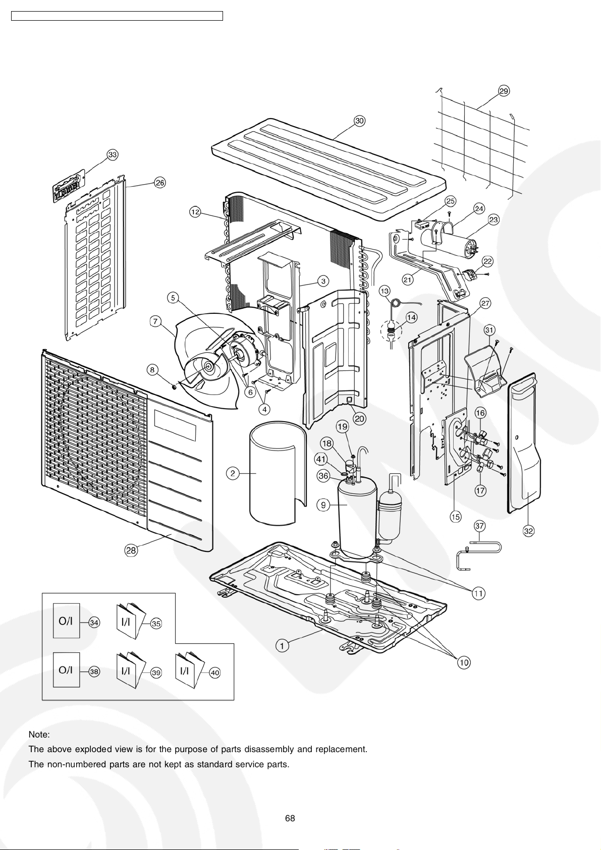
CS-V7DKE CU-V7DKE / CS-V9DKE CU-V9DKE / CS-V12DKE CU-V12DK E
17.2. CU-V9DKE CU-V12DKE
Note:
The above exploded view is for the purpose of parts disassembly and replacement.
The non-numbered parts are not kept as standard service parts.
68
Page 69

CS-V7DKE CU-V7DKE / CS-V9DKE CU-V9DKE / CS-V12DKE CU-V12DK E
18 Replacement Parts List (Outdoor Unit)
18.1. CU-V7DKE
REF. NO. PART NAME & DESCRIPTION QTY. CU-V7DKE REMARKS
1 CHASSY ASS’Y 1 CWD50K2107
2 SOUND PROOF MATERIAL 1 CWG302292
3 FAN MOTOR BRACKET 1 CWD541074
4 SCREW - FAN MOTOR BRACKET 2 CWH551060
5 FAN MOTOR 1 CWA951392 0
6 SCREW - FAN MOTOR MOUNT 3 CWH55406
7 PROPELLER FAN ASS’Y 1 CWH03K1020
8 NUT - PROPELLER FAN 1 CWH56053
9 COMPRESSOR 1 5RS084DAB21 0
10 ANTI - VIBRATION BUSHING 3 CWH50077
11 NUT - COMPRESSOR MOUNT 3 CWH56000
12 CONDENSER 1 CWB32C1495
13 CAPILLARY TUBE ASS’Y 1 CWB15K1145
14 STRAINER 1 CWB11025
15 HOLDER COUPLING ASS’Y 1 CWH351047
16 2-WAY VALVE (LIQUID) 1 CWB021233 0
17 3-WAY VALVE (GAS) 1 CWB011275 0
18 TERMINAL COVER 1 CWH171011
19 NUT - TERMINAL COVER 1 CWH7080300
20 SOUND PROOF BOARD 1 CWH151074
22 TERMINAL BOARD ASS’Y 1 CWA28K1064
23 CAPACITOR - COMPRESSOR 1 CWA312074
24 HOLDER CAPACITOR 1 CWH301038
25 CAPACITOR - FAN MOTOR 1 DS441125BPQD
26 CABINET SIDE PLATE (L) 1 CWE041110A
27 CABINET SIDE PLATE (R) 1 CWE04C1042
28 CABINET FRONT PLATE 1 CWE06K1052
29 WIRE NET 1 CWD041057A
30 CABINET TOP PLATE 1 CWE031041A
32 CONTROL BOARD COVER 1 CWH131193
34 OPERATION INSTRUCTIONS (ENG., ESP., ITA., NED., POR.,
GRE., BUL.)
35 INSTALLATION INSTRUCTIONS (ENG., FRA., ESP. & DEU.) 1 CWF612663
36 OVERLOAD PROTECTOR 1 CWA121066 0
37 HOLDER O.L.P. 1 CWH7041200
38 CHECK VALVE COMPLETE 1 CWB03C1024
39 OPERATION INSTRUCTIONS (FRA., DEU., SWE., NOR.) 1 CWF564473
40 INSTALLATION INSTRUCTIONS (ITA., NED., POR. & GRE.) 1 CWF612664
41 INSTALLATION INSTRUCTIONS (BUL.) 1 CWF612679
(20µF, 400VAC)
(2.0µF, 440VAC)
1 CWF564472
0
0
(Note)
• All parts are supplied from PHAAM, Malaysia (Vendor Code: 061).
• “O” marked parts are recommended to be kept in stock.
69
Page 70
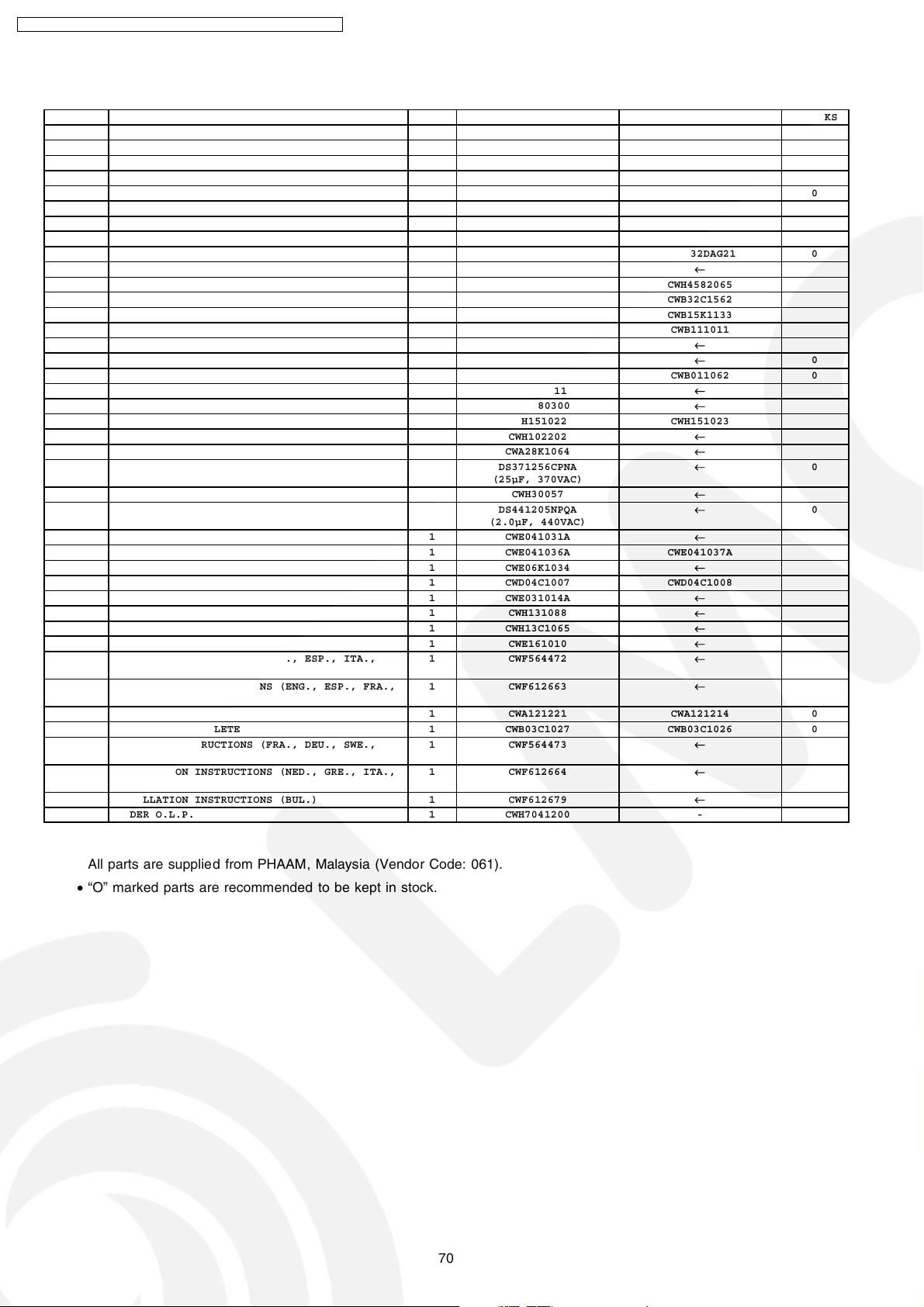
CS-V7DKE CU-V7DKE / CS-V9DKE CU-V9DKE / CS-V12DKE CU-V12DK E
18.2. CU-V9DKE CU-V12DKE
REF. NO. PART NAME & DESCRIPTION QTY. CU-V9DKE CU-V12DKE REMARKS
1 CHASSY ASS’Y 1 CWD50K2071
2 SOUND PROOF MATERIAL 1 CWG302088
3 FAN MOTOR BRACKET 1 CWD541030
4 SCREW - FAN MOTOR BRACKET 2 CWH551059
5 FAN MOTOR 1 CWA951114 CWA951116 0
6 SCREW - FAN MOTOR MOUNT 3 CWH55406
7 PROPELLER FAN ASS’Y 1 CWH03K1006
8 NUT - PROPELLER FAN 1 CWH56053
9 COMPRESSOR 1 5PS112DAG21 5PS132DAG21 0
10 ANTI - VIBRATION BUSHING 3 CWH50077
11 NUT - COMPRESSOR MOUNT 3 CWH56000 CWH4582065
12 CONDENSER 1 CWB32C1561 CWB32C1562
13 CAPILLARY TUBE ASS’Y 1 CWB15K1138 CWB15K1133
14 STRAINER 1 CWB11025 CWB111011
15 HOLDER COUPLING ASS’Y 1 CWH351023
16 2-WAY VALVE (LIQUID) 1 CWB021058
17 3-WAY VALVE (GAS) 1 CWB011063 CWB011062 0
18 TERMINAL COVER 1 CWH171011
19 NUT - TERMINAL COVER 1 CWH7080300
20 SOUND PROOF BOARD 1 CWH151022 CWH151023
21 CONTROL BOARD CASING 1 CWH102202
22 TERMINAL BOARD ASS’Y 1 CWA28K1064
23 CAPACITOR - COMPRESSOR 1 DS371256CPNA
24 HOLDER CAPACITOR 1 CWH30057
25 CAPACITOR - FAN MOTOR 1 DS441205NPQA
26 CABINET SIDE PLATE (L) 1 CWE041031A
27 CABINET SIDE PLATE (R) 1 CWE041036A CWE041037A
28 CABINET FRONT PLATE 1 CWE06K1034
29 WIRE NET 1 CWD04C1007 CWD04C1008
30 CABINET TOP PLATE 1 CWE031014A
31 PLATE - C. B. COVER 1 CWH131088
32 CONTROL BOARD COVER 1 CWH13C1065
33 HANDLE 1 CWE161010
34 OPERATION INSTRUCTIONS (ENG., ESP., ITA.,
NED., POR., GRE., BUL.)
35 INSTALLATION INSTRUCTIONS (ENG., ESP., FRA.,
DEU.)
36 OVERLOAD PROTECTOR 1 CWA121221 CWA121214 0
37 CHECK VALVE COMPLETE 1 CWB03C1027 CWB03C1026 0
38 OPERATION INSTRUCTIONS (FRA., DEU., SWE.,
NOR.)
39 INSTALLATION INSTRUCTIONS (NED., GRE., ITA.,
POR.)
40 INSTALLATION INSTRUCTIONS (BUL.) 1 CWF612679
41 HOLDER O.L.P. 1 CWH7041200 -
1 CWF564472
1 CWF612663
1 CWF564473
1 CWF612664
(25µF, 370VAC)
(2.0µF, 440VAC)
←
←
←
←
←
←
←
←
←
←
←
←
←
←
←
←
←
←
←
←
←
←
←
←
←
←
←
←
0
0
0
(Note)
All parts are supplied from PHAAM, Malaysia (Vendor Code: 061).
•
“O” marked parts are recommended to be kept in stock.
•
70
Page 71

19 Electronic Circuit Diagram
1
2
3
4
C22
0.01µ
R58
10k
Auto
SW
R59 1k
DISPLAY COMPLETE
9
SUPERSONIC COMPLETE
CN-DISP
CN-DISP
8
7
6
5
4
3
2
1
10
2
3
4
5
6
7
8
9
10
1
TIMER/AIR SW(ORG)
POWER(GRN)
QUIET(ORG)
POWERFUL(ORG)
SUPERSONIC(BLU)
C401
47µ
6.3V
BZ01
BZ
e
c
b
Q01
C143XKTX
R55
1k
R12
1k
C02
0.01µ
R88
5.1k
ELECTRONIC CONTROL UNIT
IC401
3
1
2
+
CN-HA
C23
0.01µ
R60
10k
C26 0.01µ
C25 0.01µ
C24 0.01µ
D404
D403
D401
D402
ION(GRN)
D405
D406
R401 47Ω
R07
10k
R56
1k
C01
0.01µ
R31
1k
R78
10k
C29
0.1µ
3
2
1
3
2
1
R601
1k
R603
1M
X601
IC601
R602
5.1k
C601
0.1µ
CN-SONIC
CN-SONIC
1
2
R11
1k
JP5
SW01
R68
100Ω
R13 220Ω
R14 220Ω
R15
180Ω
R27 220Ω
R73
3.3kΩ
R17
220Ω
C27
0.01µ
C28
0.01µ
C35
0.01µ
e
c
b
Q09
19.1. Indoor Unit & Outdoor Unit
SCHEMATIC DIAGRAM 1/4
CS-V7DKE CU-V7DKE / CS-V9DKE CU-V9DKE / CS-V12DKE CU-V12DK E
71
Page 72
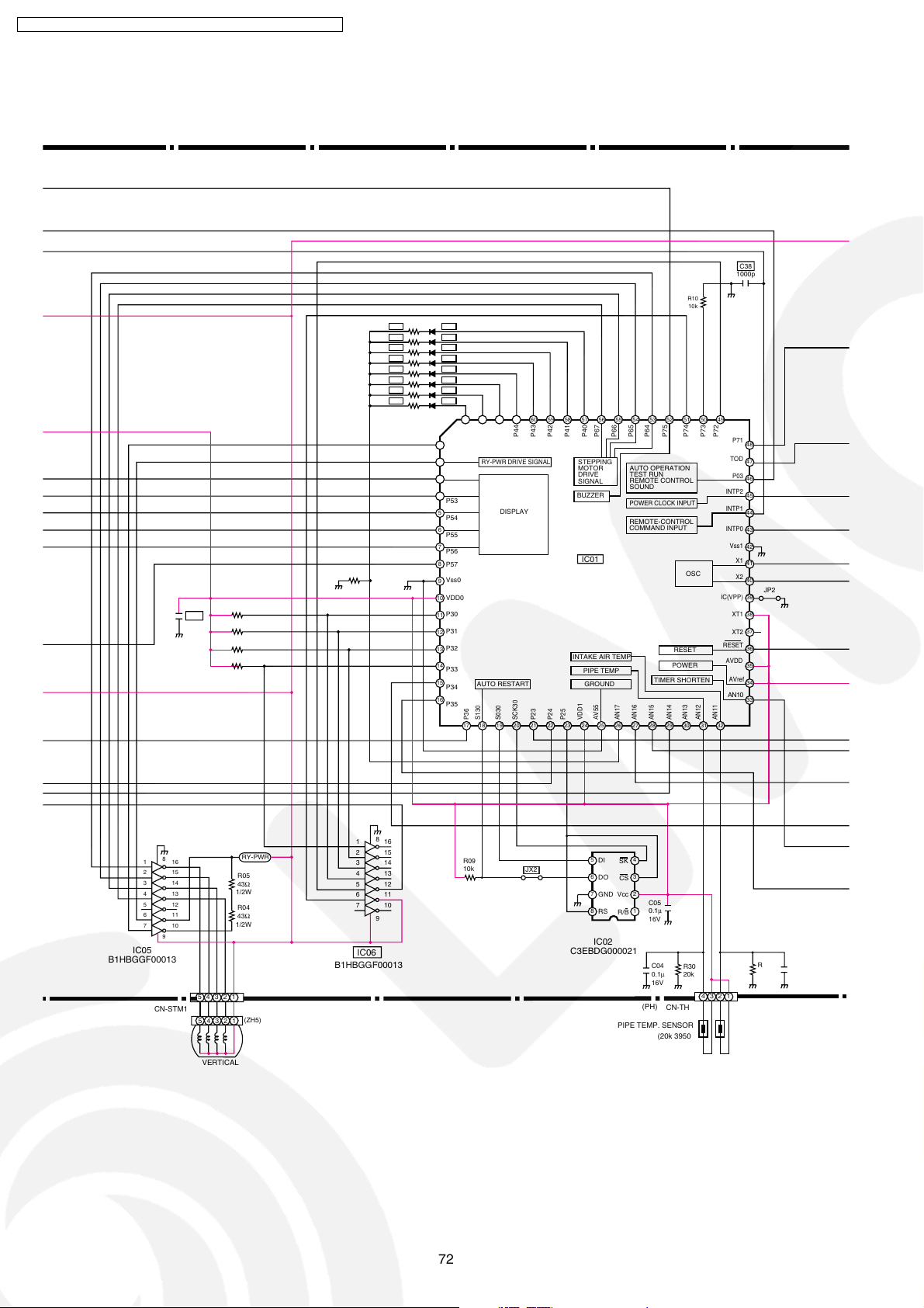
CS-V7DKE CU-V7DKE / CS-V9DKE CU-V9DKE / CS-V12DKE CU-V12DK E
SCHEMATIC DIAGRAM 2/4
R75 1k
C39
R76 1k
R74 1k
R77 1k
R06 24k
C38
1000p
R10
10k
R18
R19
R20
R21
R22
R23
R24
R25
D12
D11
D10
D09
D08
D07
D06
D05
64 63 62 61 60 59 58 57 56 55 54 53 52 51 50 49
1
P50
2
P51
3
P52
4
P53
5
P54
6
P55
7
P56
8
P57
Vss0
9
10
VDD0
P30
11
P31
12
P32
13
14
P33
15
P34
16
P35
P47
P45
P46
RY-PWR DRIVE SIGNAL
DISPLAY
AUTO RESTART
S030
S130
P36
17
18
P44
SCK30
P43
P23
P41
P42
STEPPING
MOTOR
DRIVE
SIGNAL
BUZZER
INTAKE AIR TEMP
P25
P24
P67
P40
IC01
PIPE TEMP
GROUND
AV55
VDD1
P64
P65
P66
AUTO OPERATION
TEST RUN
REMOTE CONTROL
SOUND
POWER CLOCK INPUT
REMOTE-CONTROL
COMMAND INPUT
TIMER SHORTEN
AN15
AN16
AN17
2625242322212019
P75
RESET
POWER
AN14
30292827
OSC
AN13
P72
P73
P74
P71
48
TOD
47
P03
46
INTP2
45
INTP1
44
INTP0
43
Vss1
42
X1
41
X2
40
JP2
IC(VPP)
39
XT1
38
37
XT2
RESET
36
AVDD
35
AVref
34
AN10
33
AN11
AN12
31
32
8
1
2
3
4
5
6
7
9
IC05
B1HBGGF00013
CN-STM1
8
1
16
2
16
15
14
13
12
11
10
RY-PWR
R05
43Ω
1/2W
R04
43Ω
1/2W
B1HBGGF00013
12345
(ZH5)
12345
3
4
5
6
7
IC06
15
14
13
12
11
10
R09
10k
JX2
9
5
DI
SK
6
DO
CS
Vcc
GND
8
RS
R/B
IC02
C3EBDG000021
PIPE TEMP. SENSOR
4
3
27
C05
1
0.1µ
16V
C04
R30
0.1µ
20k
16V
(PH) (RED)
CN-TH
3
1
4
2
C08
R33
0.1µ
15k
16V
AIR TEMP. SENSOR
(15k 3950)(20k 3950)
VERTICAL
72
Page 73
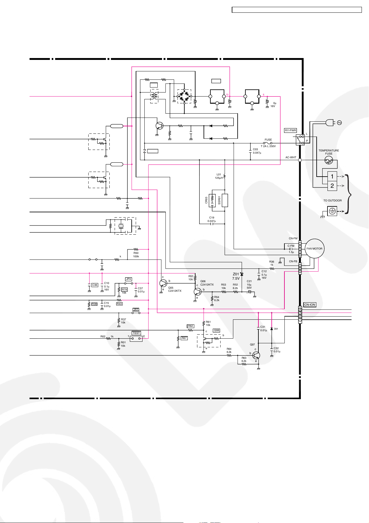
SCHEMATIC DIAGRAM 3/4
CS-V7DKE CU-V7DKE / CS-V9DKE CU-V9DKE / CS-V12DKE CU-V12DK E
Q02
C143XKTX
b
4.7k
Q03
C143XKTX
b
4.7k
JP3
C36
R38
c
10k
e
c
10k
e
R32
150k
4.096 MHz
(47pF X 2)
C18
0.1µ
16V
C10
0.1µ
16V
C15
0.01µ
R02 1k
SSR02
SSR01
R41
R49 1k
1k
R43
R44
C16
1k
0.01µ
X01
R50
100k
JP4
C37
R79
0.01µ
10k
JX1
R37
10k
TEST
12
R01
10k
R66 R48
T01
5
8
2
13
c
e
ZNR01
c
e
b
b
Q05
C2412KTX
R03 1.3k
R29
1.6k
R67
DB01
~
~
R62
IC04
REGULATOR
+
C17
3300µ
35V
C07
0.1µ
16V
OO
I
G
D16
R57 12k
D15
R47 12k
L01
125µH
C14
470µ
25V
IC03
REGULATOR
5V12V
I
G
C03
0.047µ
C11
100µ
16V
FUSE
T 2A L 250V
RY-PWR
AC-WHT
L
P
TEMPERATURE
FUSE
1
2
CR03
SSR01
C19
0.047µ
CN-FM
1
C-FM
2
3
4
1.5µ
5
D01
C32
0.01µ
CN-FB
1
2
3
4
3
2
1
CN-ION
R36
1k
C12
0.1µ
16V
C21
10µ
50V
+
C31
0.01µ
Q07
c
b
e
R54
6.2k
Z01
7.5V
R53
R52
10k
6.2k
b
R64
6.2k
R63
6.2k
R51
10k
Q06
C2412KTX
c
b
e
R61
10k
Q08
c
e
TO OUTDOOR
FAN MOTOR
73
Page 74
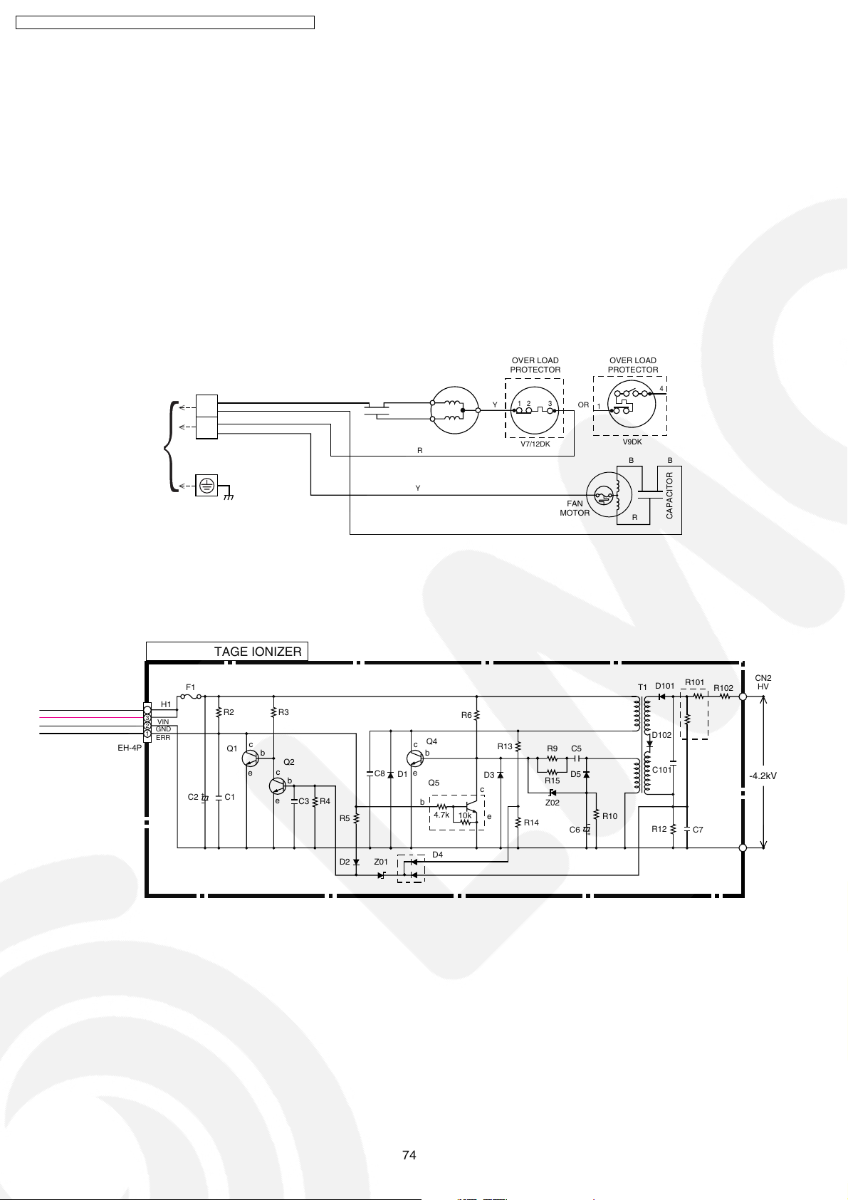
CS-V7DKE CU-V7DKE / CS-V9DKE CU-V9DKE / CS-V12DKE CU-V12DK E
SCHEMATIC DIAGRAM 4/4
1
2
TO INDOOR
HIGH VOLTAGE IONIZER
F1
CH1
4
3
VIN
2
GND
1
ERR
EH-4P
C2 C1
OVER LOAD
D3
c
e
PROTECTOR
Y
R13
1
23
V7/12DK
R14
MOTOR
R9
R15
Z02
CAPACITOR
R2
Q1
R3
c
b
Q2
c
e
b
e
C3 R4
C8
R5
BB
R
GR
Y
c
e
D1
COMPRESSOR
R6
Q4
b
Q5
b
4.7k
10k
FAN
C5
D5
C6
OR
OVER LOAD
PROTECTOR
1
V9DK
R10
4
BB
CAPACITOR
R
R102
CN2
HV
R101
D101
T1
D102
C101
R12
C7
-4.2kV
D2
Z01
D4
CN3
GND
74
Page 75
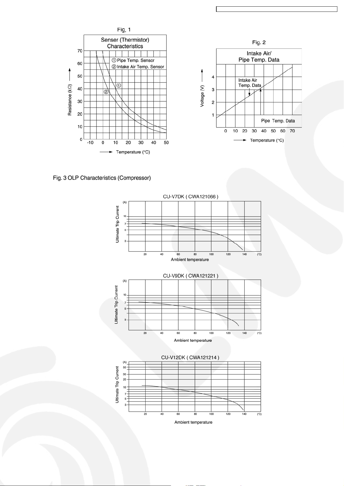
CS-V7DKE CU-V7DKE / CS-V9DKE CU-V9DKE / CS-V12DKE CU-V12DK E
75
Page 76

CS-V7DKE CU-V7DKE / CS-V9DKE CU-V9DKE / CS-V12DKE CU-V12DK E
How to use electronic circuit diagram
TIMER TABLE
Test Mode
Name Time (When test point Remarks
Short-circuited)
Real Timer 1hr. 1 min.
10 min. 10 sec.
1 min. 1 sec.
Time Delay Safety Control 2 min. 58 sec. 0 sec.
Forced Operation 60 sec. 0 sec.
Time Save Control 7 min. 4.2 sec.
Anti-Freezing 4 min. 0 sec.
Auto Mode Judgement 20 sec. 0 sec.
Soft Dry OFF 6 min. 36 sec.
ON 10 min. 60 sec. Soft Dry: 10 min. operation
Cooling 40 sec. 4 sec.
Deodorizing Control
Soft Dry 40 sec. 4 sec.
Comp. Reverse Rotation Detection 5 min. 30 sec. Comp. ON 5 min. and above
Comp./ Fan Motor Delay Timer 1.6 sec. 0 sec.
Powerful Mode Operation 15 min. 15 sec.
Random Auto Restart Control 0 ~ 62 sec. 0 ~ 6.2 sec.
70 sec. 7 sec.
20 sec. 2 sec.
180 sec. 18 sec.
360 sec. 36 sec.
2 min. 0 sec.
76
Page 77
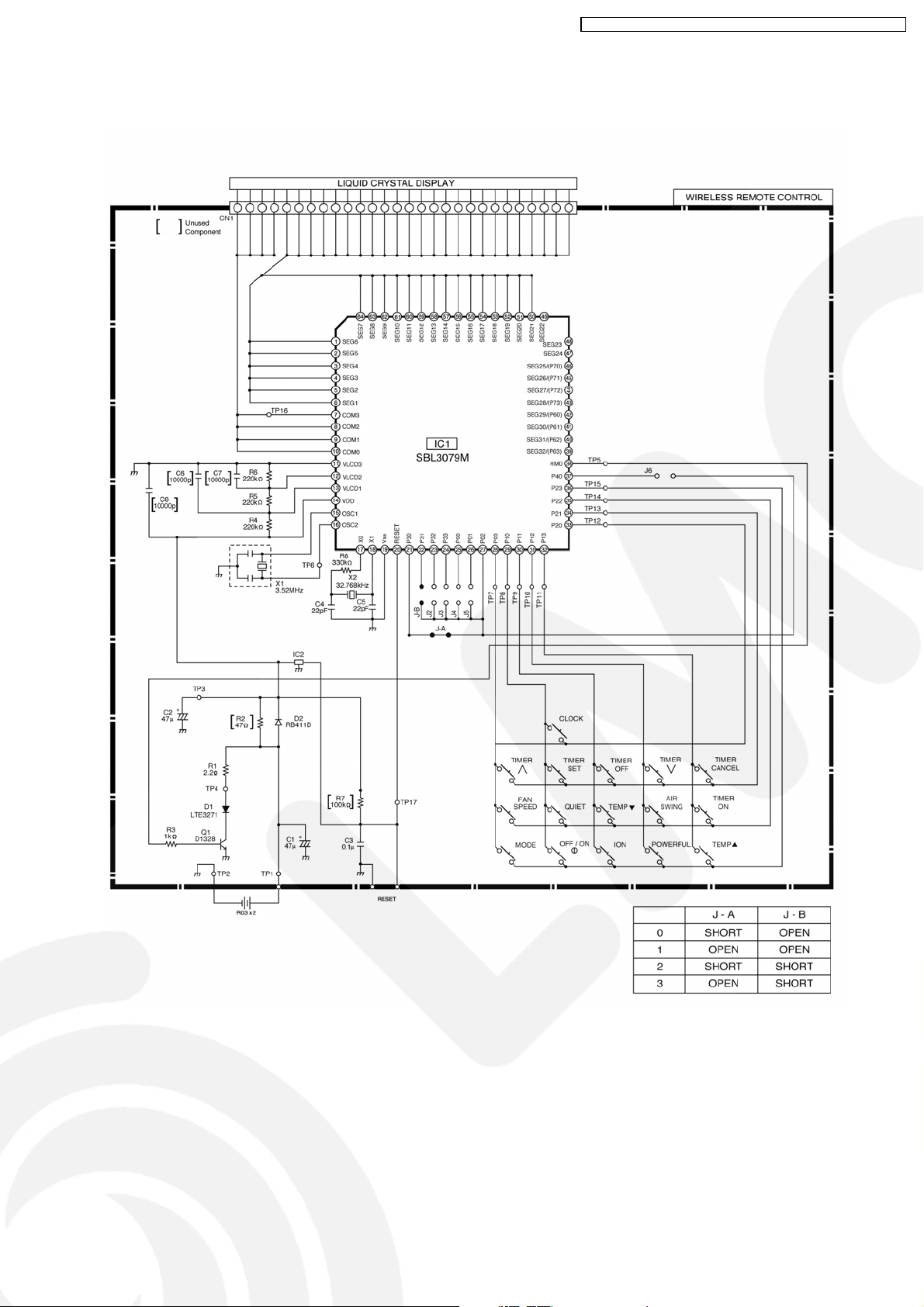
19.2. Remote Control
CS-V7DKE CU-V7DKE / CS-V9DKE CU-V9DKE / CS-V12DKE CU-V12DK E
77
Page 78
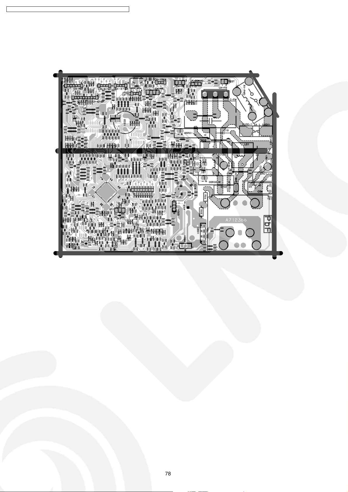
CS-V7DKE CU-V7DKE / CS-V9DKE CU-V9DKE / CS-V12DKE CU-V12DK E
19.3. Print Pattern
Indoor Unit Printed Circuit Board
BOTTOM VIEW
78
Page 79

TOP VIEW
CS-V7DKE CU-V7DKE / CS-V9DKE CU-V9DKE / CS-V12DKE CU-V12DK E
79
Page 80
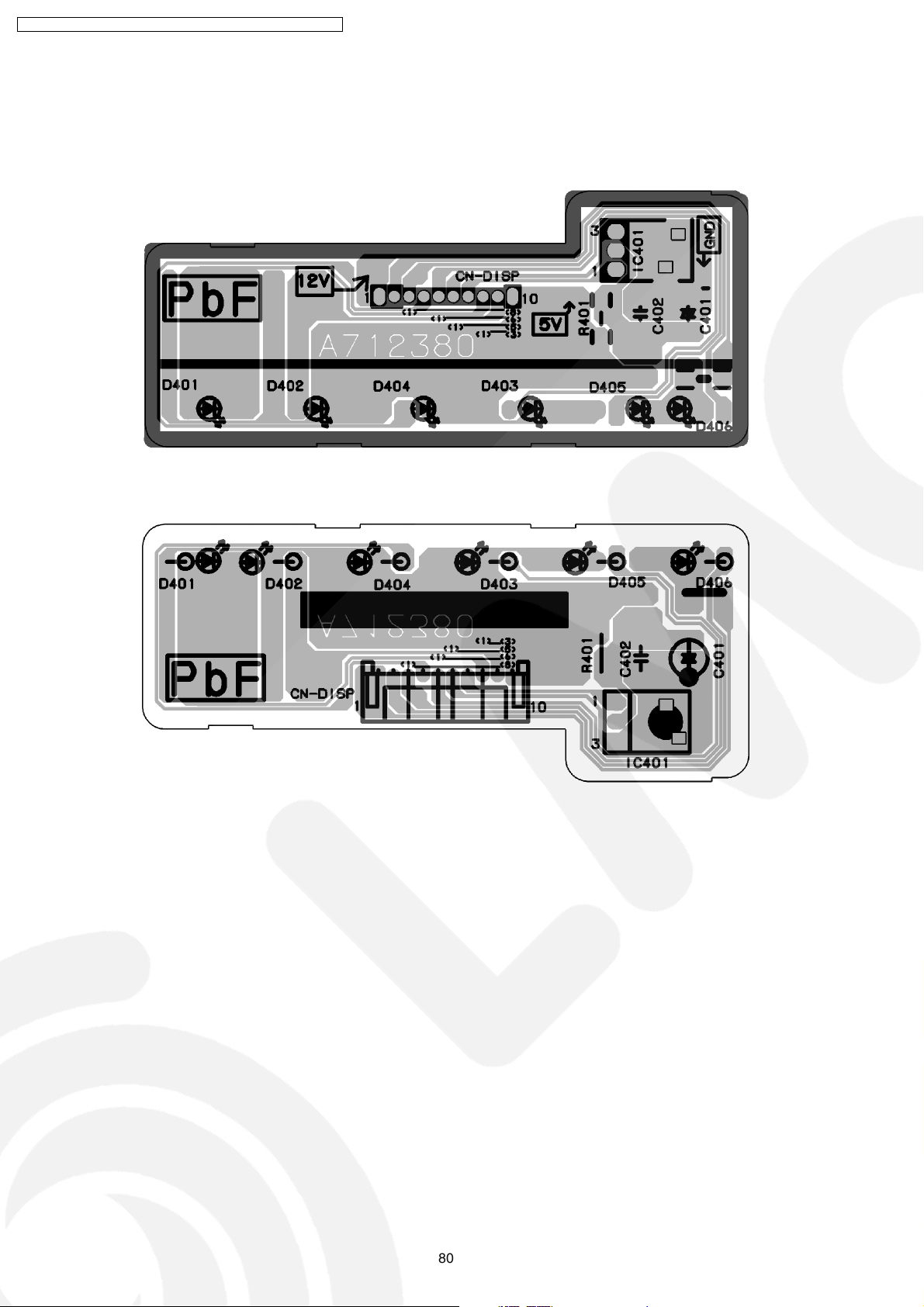
CS-V7DKE CU-V7DKE / CS-V9DKE CU-V9DKE / CS-V12DKE CU-V12DK E
19.4. Print Pattern
Indicator & Receiver Printed Circuit Board
BOTTOM VIEW
TOP VIEW
80
[PHAAM] Printed in Malaysia
 Loading...