

Panasonic CS-ME7DKDG, CS-ME7DKEG, CS-E9DKDW, CS-E9DKEW, CS-E12DKDW Service Manual
...
© 2006 Matsushita Electric Industrial Co., Ltd. All
rights reserved. Unauthorized copying and
distribution is a violation of law.
INDOOR UNIT
CS-ME7DKEG CS-ME10DD3EW
CS-ME10DTEG CS-E15DB4EW
CS-ME7DKDG CS-E9DKDW
CS-E9DKEW CS-E12DKDW
CS-E12DKEW CS-E15DKDW
CS-E15DKEW CS-E18DKDW
CS-E18DKEW CS-E15DTEW
CS-E18DTEW CS-E15DD3EW
CS-E18DD3EW CS-E18DB4EW
OUTDOOR UNIT
CU-3E18EBE
Multi Air Conditioner
Order No. RAC0602011C2
1 Safety Precautions 3
2 Features
5
2.1. Wall Type
6
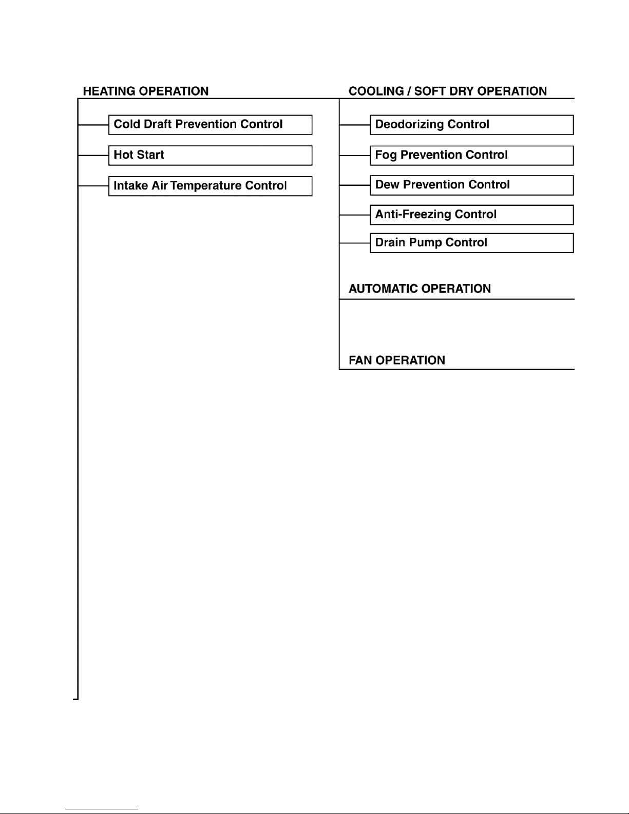
2.2. Duct Type
9
2.3. Ceiling Floor Type
12
2.4. Mini-Cassette Type
14
3 Product Specifications
16
3.1. Wall Type
16
3.2. Duct Type
17
3.3. Ceiling Floor Type
18
3.4. Mini-Cassette Type
19
3.5. Outdoor unit: CU-3E18EBE
20
4 Dimensions
21
4.1. Wall Type
21
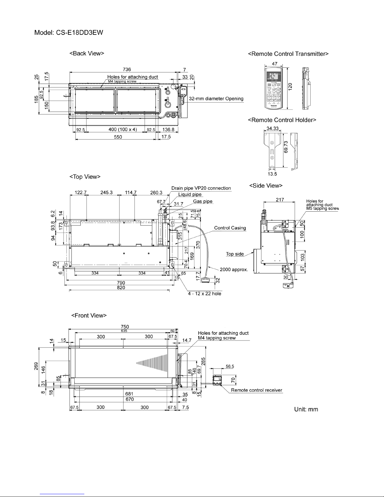
4.2. Duct Type
23
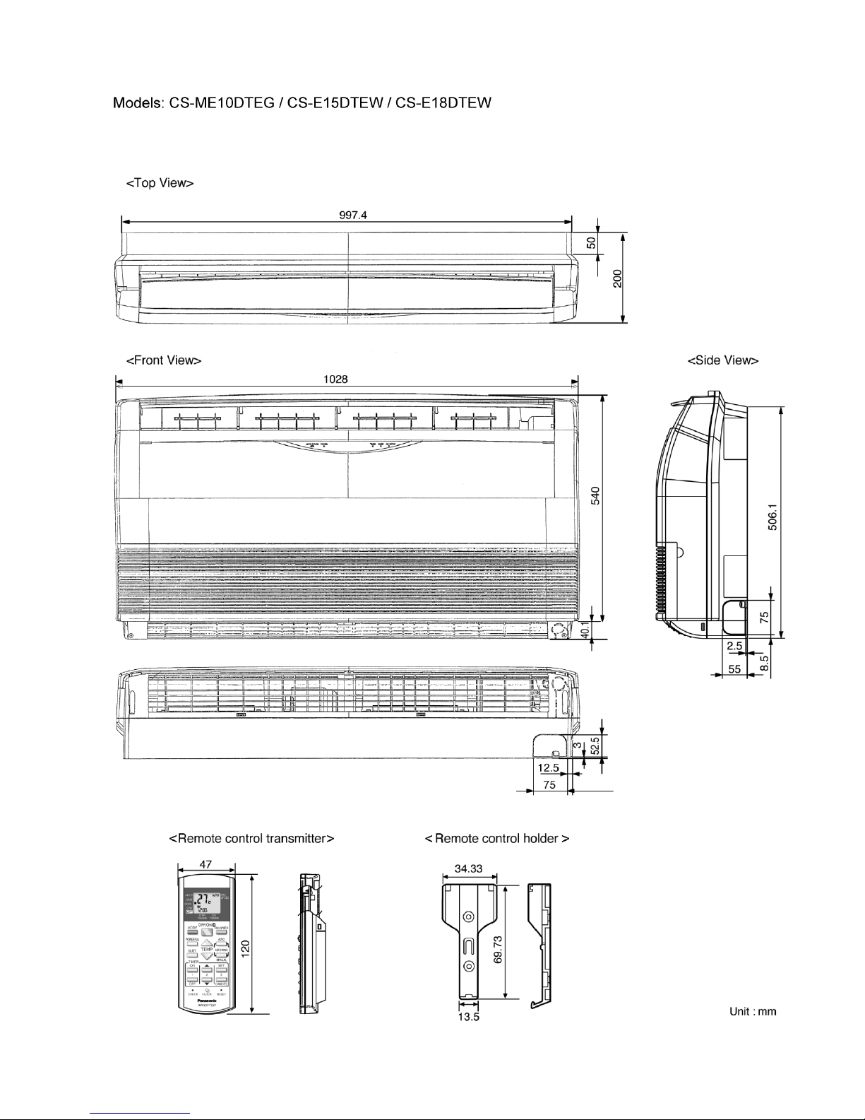
4.3. Ceiling Floor Type
25
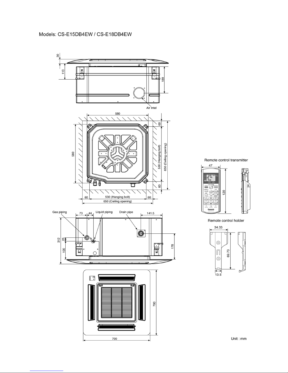
4.4. Mini-Cassette Type
26
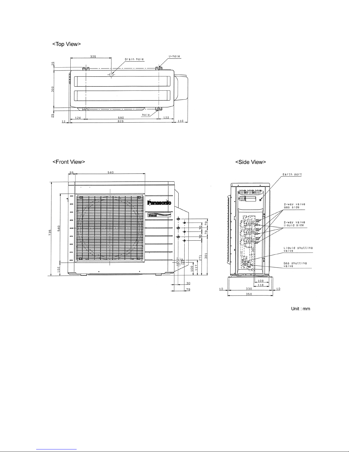
4.5. Outdoor Unit
27
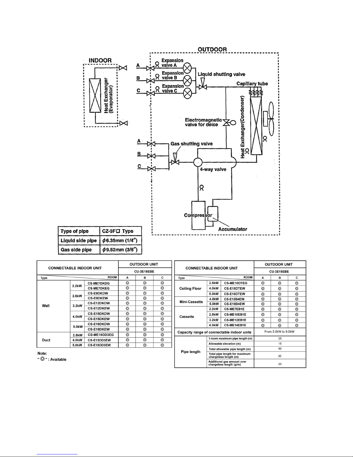
5 Refrigeration Cycle Diagram
28
6 Wiring Diagram
29
6.1. Wall Type
29
6.2. Duct Type
30
6.3. Ceiling Floor Type
31
6.4. Mini-Cassette Type
32
6.5. Outdoor Unit
33
7 Electronic Circuit Diagram
34
8 Operation Details
36
8.1. Wall Type
36
8.2. Duct Type
53
8.3. Ceiling Floor Type
59
8.4. Mini-Cassette Type
73
8.5. Outdoor Unit Operation
87
8.6. Forced Cooling Operation Control
88
8.7. Wiring Error Check Control
89
8.8. Outdoor Unit - Check Point
90
9 Self Diagnosis Display
91
9.1. Breakdown Self Diagnosis Function (Three Digits
Alphanumeric Code)
91
9.2. Error Code
92
10 Installation Information
96
11 Installation Instructions
97
12 Disassem bly of Parts
108
12.1. Wall Type
108
12.2. Duct Type
110
12.3. Ceiling Floor Type
112
12.4. Mini-Cassette Type
113
12.5. Outdoor Unit
115
13 Technical Data
117
13.1. Operation Characteristics
117
14 Exploded View and Replacement Parts List
119
14.1. Wall Type
119
14.2. Duct Type
125
14.3. Ceiling Floor Type
127
14.4. Mini-Cassette Type
129
14.5. Outdoor Unit
134
CONTENTS
Page Page
2
1 Safety Precautions
• Read the following “SAFETY PRECAUTIONS” carefully before perform any servicing.
• Electrical work must be installed or serviced by a licensed electrician. Be sure to use the correct rating of the power plug and
main circuit for the model installed.
• The caution items stated here must be followed because these important contents are related to safety. The meaning of each
indication used is as below.
Incorrect installation or servicing due to ignoring of the instruction will cause harm or damage, and the seriousness is classified
by the following indications.
This indication shows the possibility of causing death or serious injury.
This indication shows the possibility of causing injury or damage to properties.
The items to be followed are classified by the symbols:
This symbol denotes item that is PROHIBITED from doing.
• Carry out test running to confirm that no abnormality occurs after the servicing. Then, explain to user the operation, care and
maintenance as stated in instructions. Please remind the customer to keep the operating instructions for future reference.
1. Engage dealer or specialist for installation and servicing. If installation or servicing done by the user is defective, it will cause water leakage,
electrical shock or fire.
2. Install according to this installation instructions strictly. If installation is defective, it will cause water leakage, electrical shock or fire.
3. Use the attached accessories parts and specified parts for installation and servicing. Otherwise, it will cause the set to fall, water leakage,
fire or electrical shock.
4. Install at a strong and firm location which is able to withstand the set´s weight. If the strength is not enough or installation is not properly
done, the set will drop and cause injury.
5. For electrical work, follow the local national wiring standard, regulation and the installation instruction. An independent circuit and single
outlet must be used. If electrical circuit capacity is not enough or defect found in electrical work, it will cause electrical shock or fire.
6. Use the specified cable and connect tightly for indoor/outdoor connection. Connect tightly and clamp the cable so that no external force will
be acted on the terminal. If connection or fixing is not perfect, it will cause heat-up or fire at the connection.
7. Wire routing must be properly arranged so that control board cover is fixed properly. If control board cover is not fixed perfectly, it will cause
heat-up at connection point of terminal, fire or electrical shock.
8. When connecting the piping, do not allow air or any substances other than the specified refrigerant to enter the
refrigeration cycle. Otherwise, this may lower the capacity, cause abnormally high pressure in the refrigeration cycle, and
possibly result in explosion and injury.
9. Thickness of copper pipes used must be more than 0.8 mm. Never use copper pipes thinner than 0.8 mm.
10. It is desirable that the amount of residual oil is less than 40 mg/10 m.
11. Do not modify the length of the power supply cord or use of the extension cord, and do not share the single outlet with
other electrical appliances. Otherwise, it will cause fire or electrical shock.
1. The equipment must be earthed. It may cause electrical shock if grounding is not perfect.
2. Do not install the unit at place where leakage of flammable gas may occur. In case gas leaks and accumulates at
surrounding of the unit, it may cause fire.
3. Carry out drainage piping as mentioned in installation instructions. If drainage is not perfect, water may enter the room and damage the
furniture.
3
4. Pb free solder has a higher melting point than standard solder; typically the melting point is 50 - 70°F (30 - 40°C) higher. Please use a high
temperature soldering iron. In case of the soldering iron with temperature control, please set it to 700 20°F (370 10°C).
Pb free solder will tend to splash when heated too high (about 1100°F/600°C).
1. Selection of the installation location. Select an installation location which is rigid and strong enough to support or hold the unit, and select
a location for easy maintenance.
2. Power supply connection to the conditioner. Connect the power supply cord of the air conditioner to the mains using one of the following
methods. Power supply point shall be the place where there is ease for access for the power disconnection in case of emergency.
In some countries, permanent connection of this room air conditioner to the power supply is prohibited.
1. Power supply connection to the receptacle using a power plug. Use an approved power plug with earth pin for the connection to the
socket.
2. Power supply connection to a circuit breaker for the permanent connection. Use an approved circuit breaker for the permanent
connection. It must be a double pole switch with a minimum 3.5 mm contact gap.
3. Do not release refrigerant during piping work for installation, servicing reinstallation and during repairing a refrigeration parts. Take care of
the liquid refrigerant, it may cause frostbite.
4. Installation work. It may need two people to carry out the installation work.
5. Do not install this appliance in a laundry room or other location where water may drip from the ceiling, etc.
4
• Serviceability
− Self diagnosis
− T est Run at both Cooling and Heating rated frequency
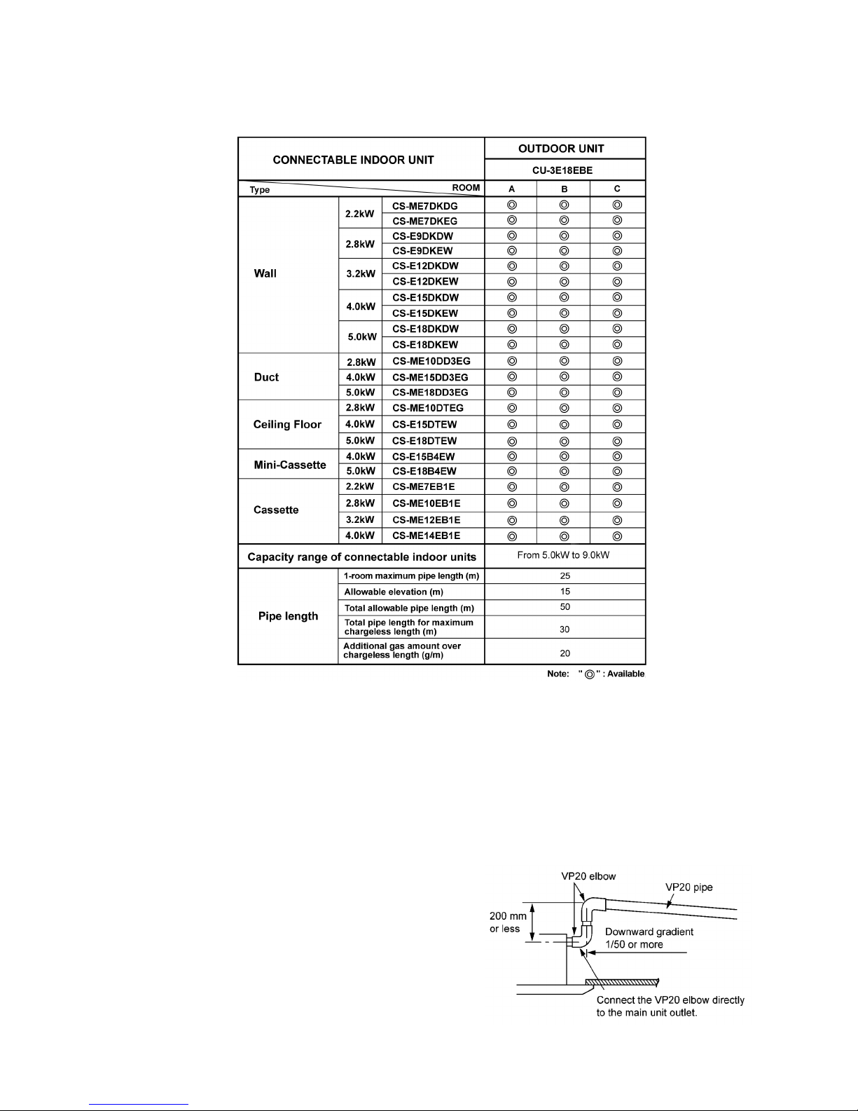
• Built-in drain pump (Cassette and Duct type)
− A drain pump is built in.
The pipe can rise to 200 mm above the drain outlet.
2 Features
• Product
− A single OUTDOOR unit enable air conditioning of up to three separate rooms for CU-3E18EBE.
Remarks for CU-3E18EBE:
1. At least two indoor units must be connected.
2. The total nominal cooling capacity of indoor units that will be connected to outdoor unit must be within connectable
capacity range of indoor unit. (shown in the above table.)
Example: The below indoor units combination is possible to connect CU-3E18EBE.
(Total nominal capacity of indoor units is 5.0 kW and 9.0 kW)
1) Two CS-ME7DKEG only. (Total nominal cooling capacity is 4.4 kW.)
2) Three CS-E12DKEW only. (Total nominal cooling capacity is 9.6 kW.)
5
2.1. Wall Type
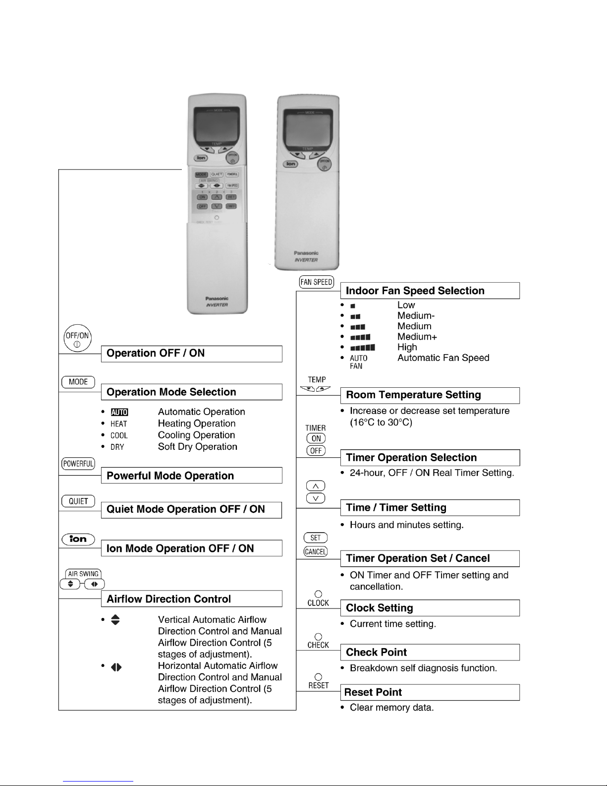
2.1.1. Remote Control
6
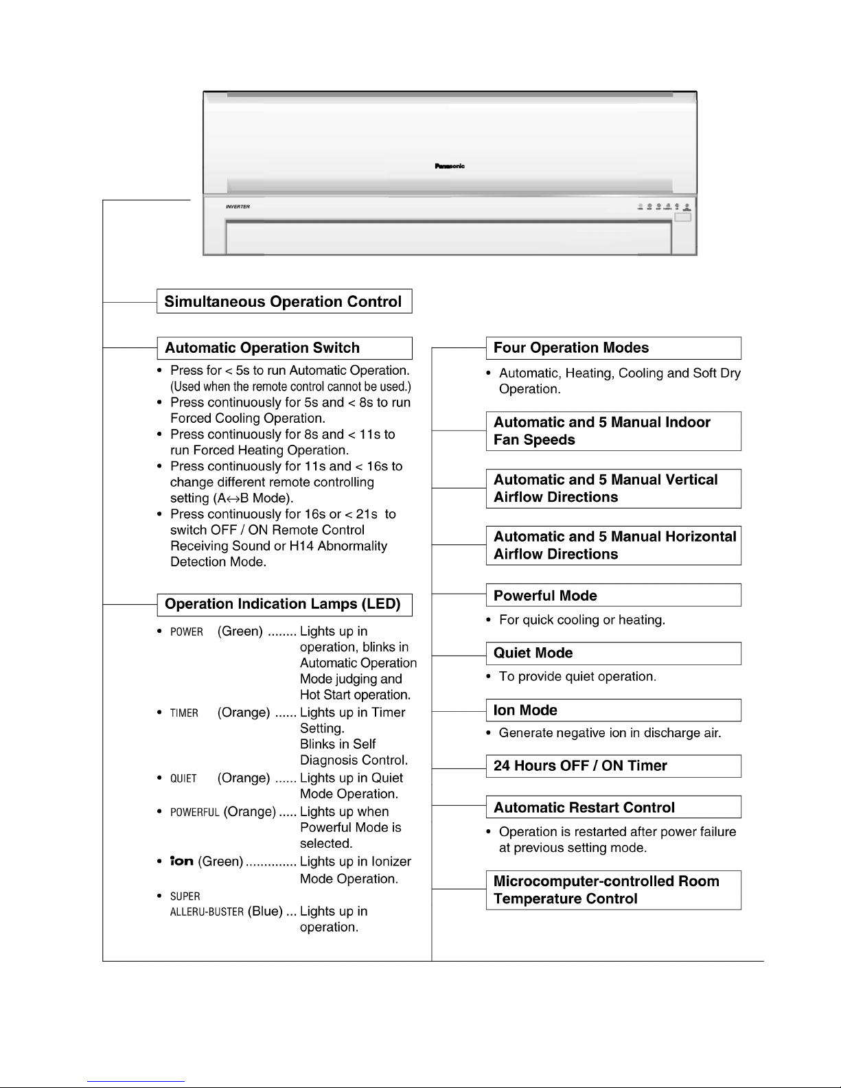
2.1.2. Indoor Unit
7
8

2.2. Duct Type
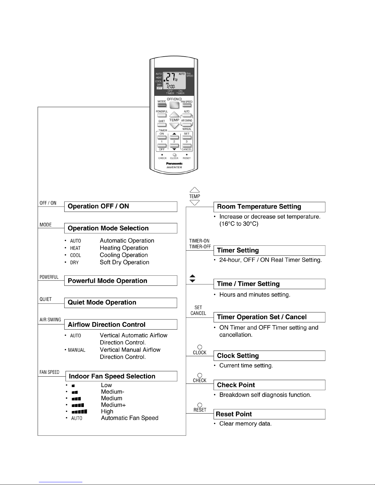
2.2.1. Remote Control
9
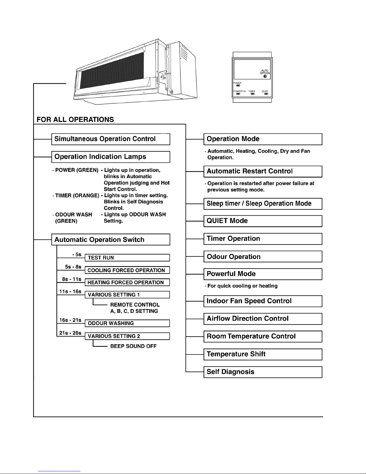
2.2.2. Indoor Unit
10
11
2.3. Ceiling Floor Type
2.3.1. Remote Control
12
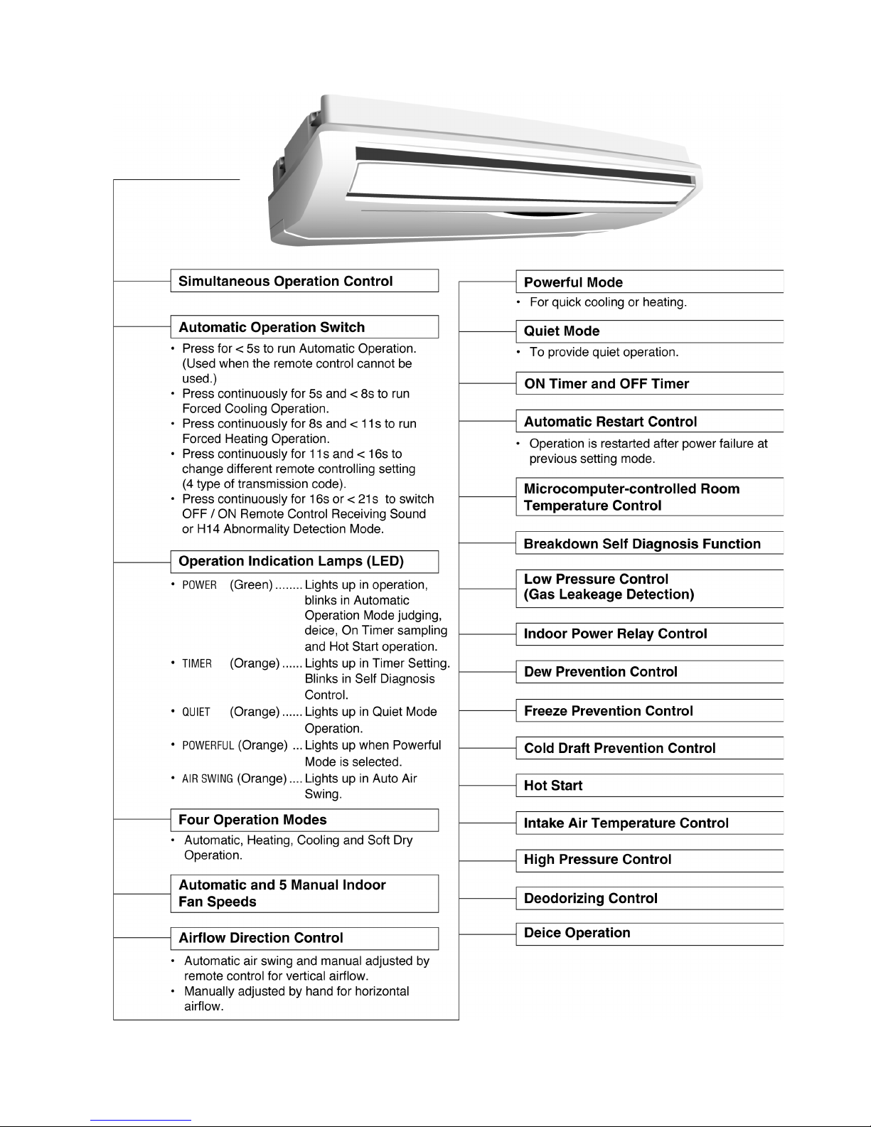
2.3.2. Indoor Unit
13

2.4. Mini-Cassette Type
2.4.1. Remote Control
14
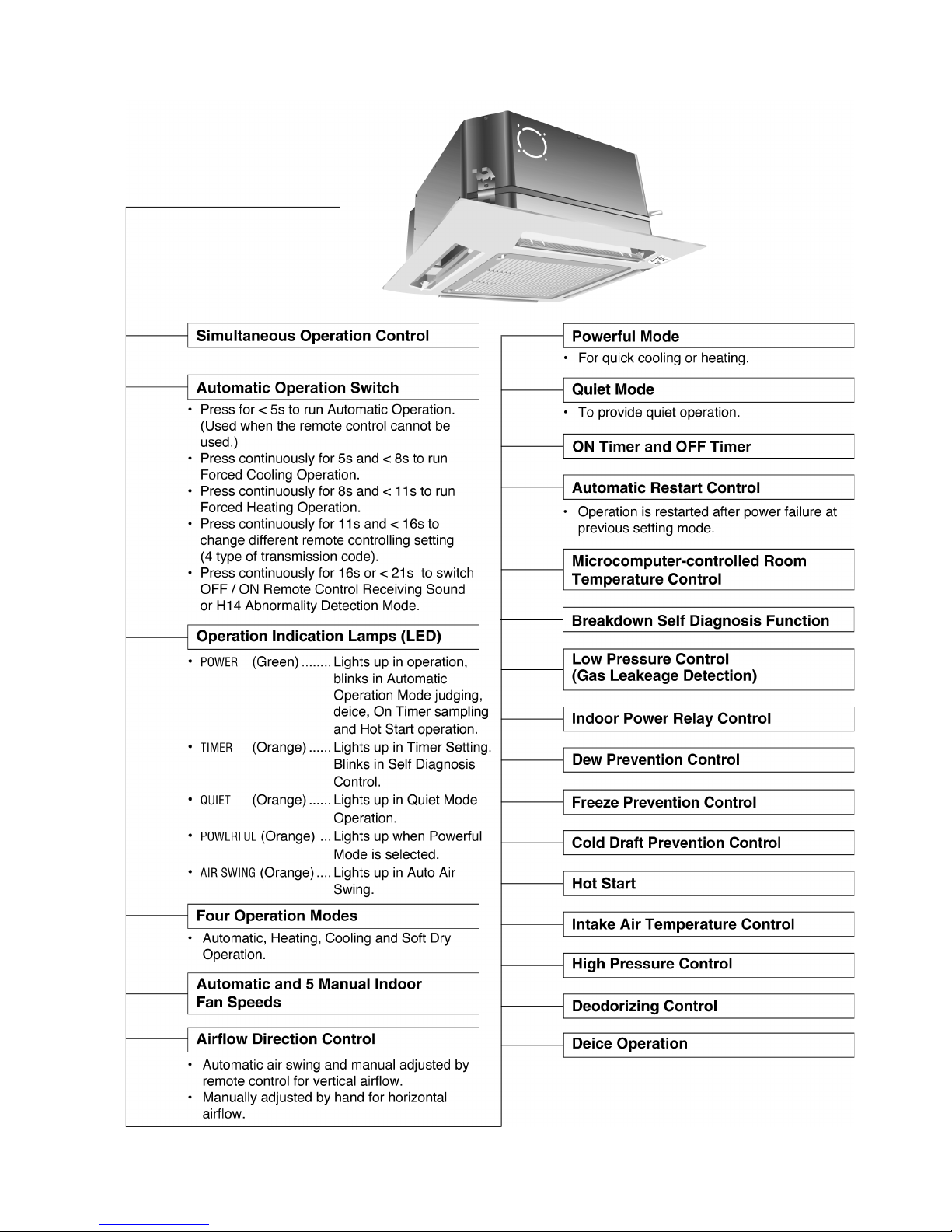
2.4.2. Indoor Unit
15
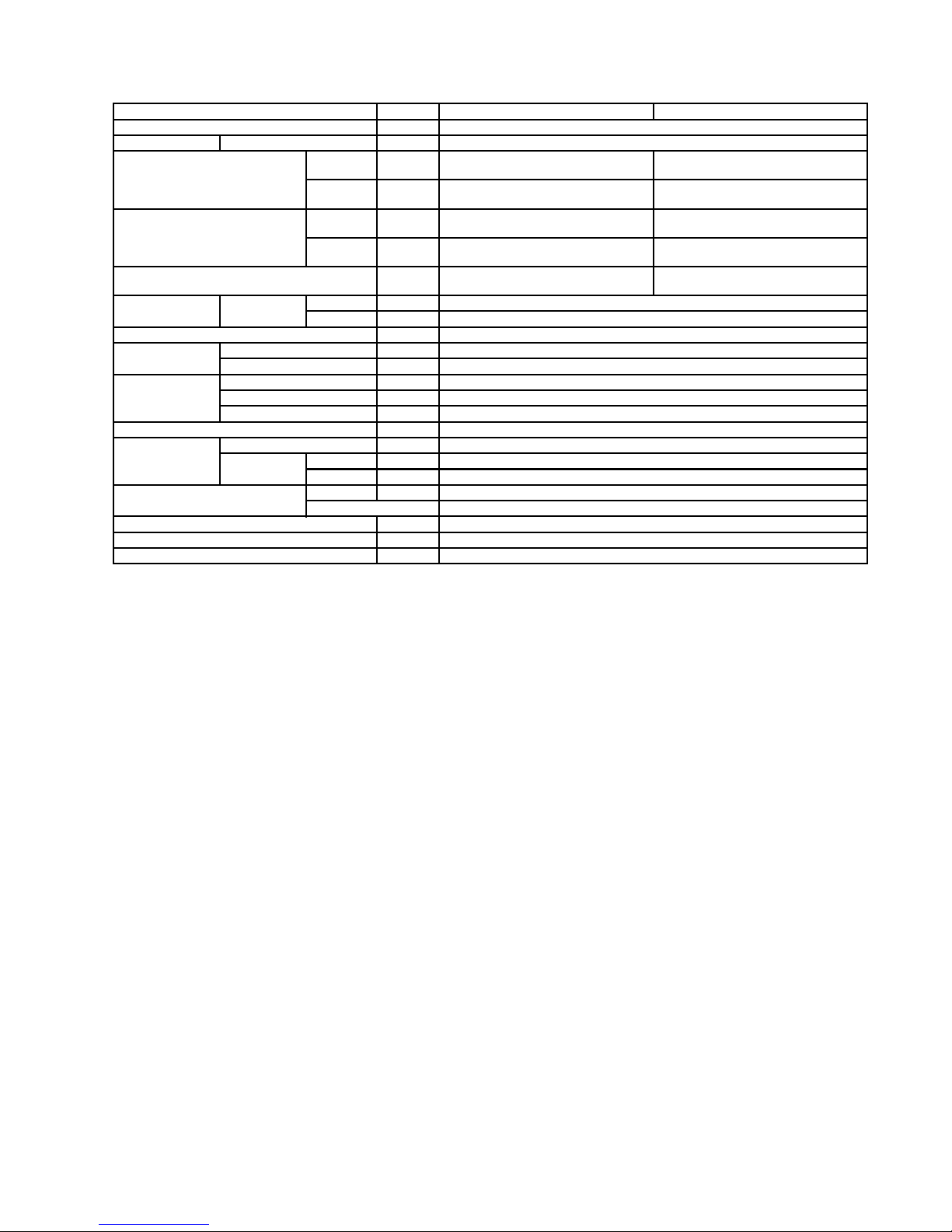
3 Product Specifications
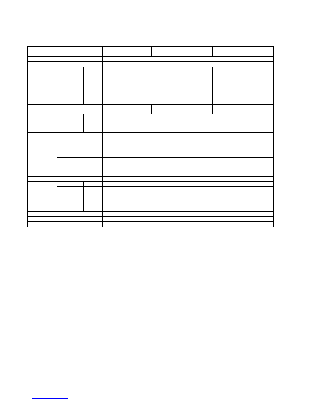
3.1. Wall Type
Model Unit CS-ME7DKEG CS-E9DKEW CS-E12DKEW CS-E15DKEW CS-E18DKEW
CS-ME7DKDG CS-E9DKDW CS-E12DKDW CS-E15DKDW CS-E18DKDW
Item Wall Type
Power Source Outdoor power Single 230V 50Hz
Air Volume Cooling m3/min
(cfm)
High: 9.6
(340)
High: 10.7
(380)
High: 11.0
(390)
High: 13.9
(490)
Heating m3/min
(cfm)
High: 10.0
(350)
High: 11.2
(400)
High: 11.8
(420)
High: 15.2
(540)
Noise Level Cooling
(Power)
dB(A)
(dB)
High: 40 (53)
Low: 29
High: 44 (57)
Low: 32
High: 44 (57)
Low: 32
High: 46 (59)
Low: 33
Heating
(Power)
dB(A)
(dB)
High: 40 (53)
Low: 29
High: 44 (57)
Low: 32
High: 44 (57)
Low: 33
High: 46 (59)
Low: 35
Moisture Removal L/h
(Pint/h)
1.3
(2.8)
1.6
(3.4)
1.8
(3.8)
2.3
(4.8)
2.8
(5.9)
Refrigeration
Piping
Connection Liquid mm
(inch)
6.35 (1/4”)
Gas mm
(inch)
9.52 (3/8”) 12.7 (1/2”)
Type of Indoor / Outdoor connecting cable mm 4 × 1.5 mm2flexible cord, type designation 245 IEC 57 (H05RN-F)
Drain
Hose
Inner diameter mm 16
Length m 0.65
Dimensions Height mm
(inch)
280 (11 - 1/32) 275 (10 - 13/16)
Width mm
(inch)
799 (31 - 15/32) 998 (39 - 9/32)
Depth mm
(inch)
183 (7 - 7/32) 230 (9 - 1/16)
Net Weight lb (kg) 20 (9.0) 24 (11.0)
Air Circulation Type Cross-flow Fan
Motor Type Transistor (8-poles)
Output W 30
Heat Exchanger Plate fin configuration, forced draft
Row /
Stage
2/15
Thermostat Electronic Control
Protection Device Electronic Control
Air Filter P.P. Honeycomb
•
Specifications are subject to change without notice for further improvement.
16
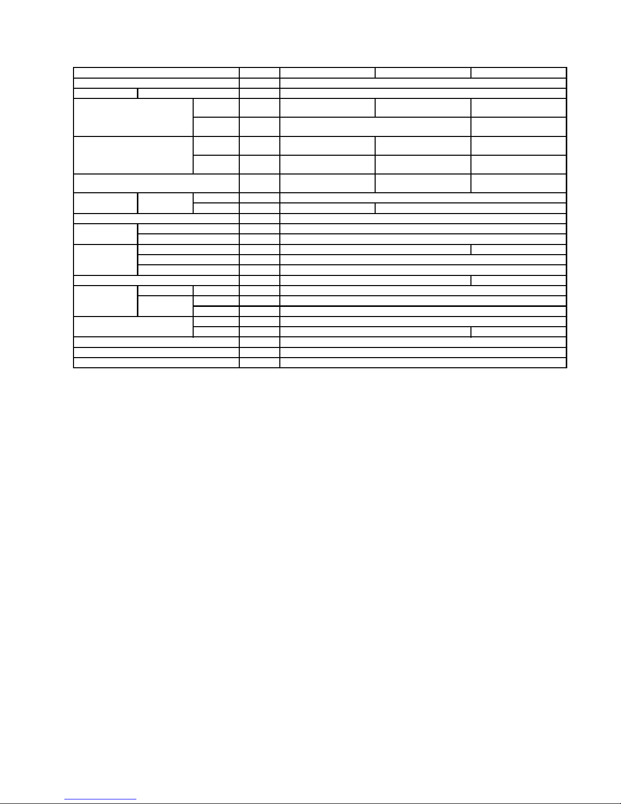
3.2. Duct Type
Model Unit CS-ME10DD3EG CS-E15DD3EW CS-E18DD3EW
Item Duct Type
Power Source Outdoor power Single 230V 50Hz
Air Volume Cooling m3/min
(cfm)
High: 7.0
(250)
High: 7.8
(280)
High: 10.3
(360)
Heating m3/min
(cfm)
High: 8.9
(310)
High: 12.6
(440)
Noise Level Cooling
(Power)
dB(A)
(dB)
High: 31 (47)
Low: 27
High: 33 (49)
Low: 27
High: 41 (57)
Low: 30
Heating
(Power)
dB(A)
(dB)
High: 35 (51)
Low: 27
High: 35 (51)
Low: 28
High: 41 (57)
Low: 32
Moisture Removal L/h
(Pint/h)
1.6
(3.4)
2.3
(4.9)
2.8
(5.9)
Refrigeration
Piping
Connection Liquid mm (inch) 6.35 (1/4”)
Gas mm (inch) 9.52 (3/8”) 12.7 (1/2”)
Type of Indoor / Outdoor connecting cable mm 4 × 1.5 mm2flexible cord, type designation 245 IEC 57 (H05RN-F)
Drain
Hose
Inner diameter mm VP20
Length m 0.255
Dimensions Height mm (inch) 235 (9 - 1/4) 285 (11 - 7/32)
Width mm (inch) 750 (29 - 17/32)
Depth mm (inch) 370 (14 - 9/16)
Net Weight lb (kg) 17 (37) 18 (40)
Air Circulation Type Sirocco Fan
Motor Type Transistor 8-poles
Output W 30
Heat Exchanger Plate fin configuration, forced draft
Row / Stage 2/8 3/12
Thermostat Electronic Control
Protection Device Electronic Control
Air Filter —
•
Specifications are subject to change without notice for further improvement.
17
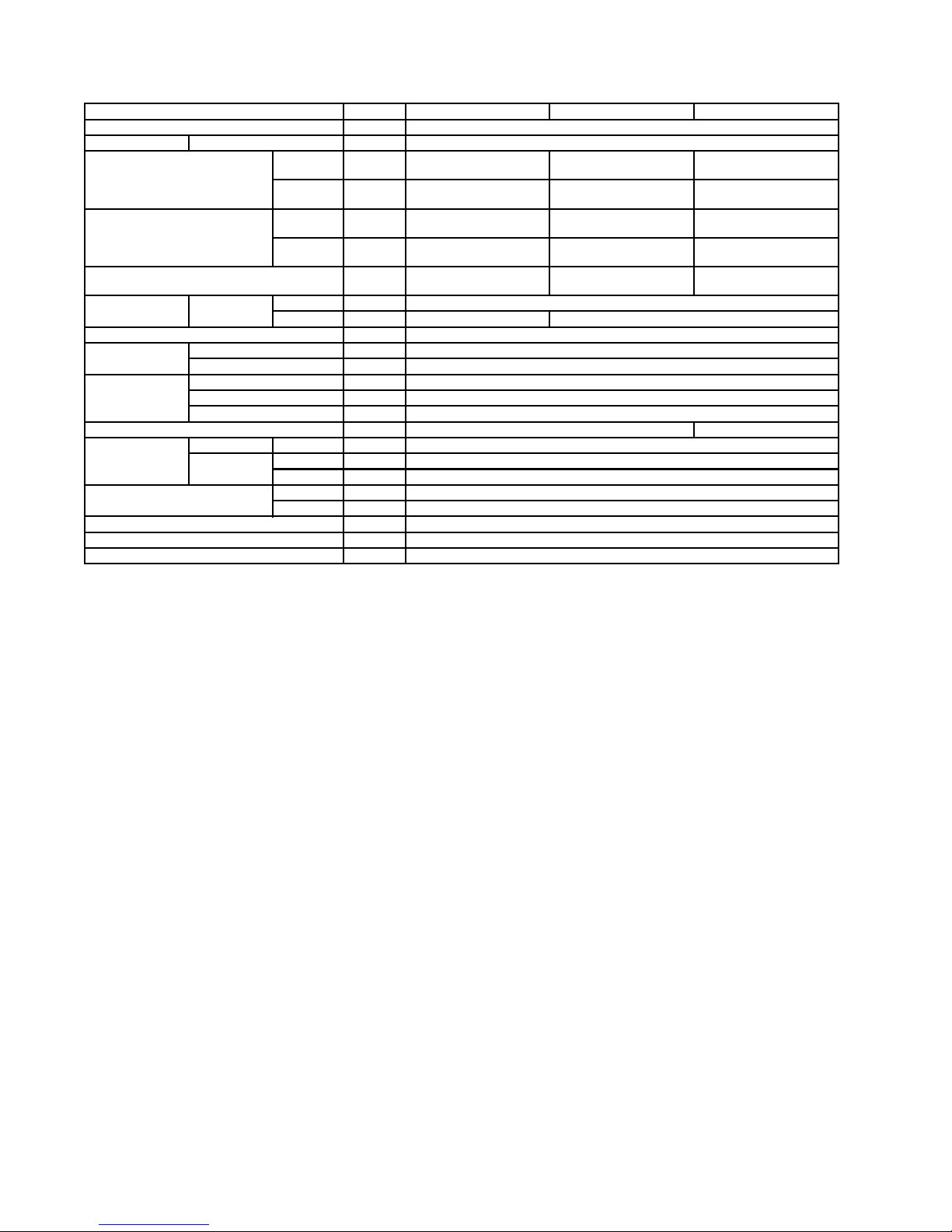
3.3. Ceiling Floor Type
Model Unit CS-ME10DTEG CS-E15DTEW CS-E18DTEW
Item Ceiling Floor Type
Power Source Outdoor power Single 230V 50Hz
Air Volume Cooling m3/min
(cfm)
High: 9.3
(330)
High: 11.7
(410)
High: 12.1
(430)
Heating m3/min
(cfm)
High: 9.3
(330)
High: 12.0
(420)
High: 12.5
(440)
Noise Level Cooling
(Power)
dB(A)
(dB)
High: 39 (52)
Low: 31
High: 45 (58)
Low: 37
High: 46 (59)
Low: 39
Heating
(Power)
dB(A)
(dB)
High: 40 (53)
Low: 31
High: 45 (58)
Low: 33
High: 47 (60)
Low: 35
Moisture Removal L/h
(Pint/h)
1.6
(3.3)
2.3
(4.9)
2.8
(5.9)
Refrigeration
Piping
Connection Liquid mm (inch) 6.35 (1/4”)
Gas mm (inch) 9.52 (3/8”) 12.7 (1/2”)
Type of Indoor / Outdoor connecting cable mm 4 × 1.5 mm2flexible cord, type designation 245 IEC 57 (H05RN-F)
Drain
Hose
Inner diameter mm 16
Length m 0.65
Dimensions Height mm (inch) 540 (21 - 9/32)
Width mm (inch) 1028 (40 - 1/2)
Depth mm (inch) 200 (7 - 7/8)
Net Weight lb (kg) 17 (37) 18 (40)
Air Circulation Type Backward Fan
Motor Type Transistor 8-poles
Rate Output W 51
Heat Exchanger Plate fin configuration, forced draft
Row / Stage 2/12
Thermostat Electronic Control
Protection Device Electronic Control
Air Filter P.P. Honeycomb
•
Specifications are subject to change without notice for further improvement.
18
3.4. Mini-Cassette Type
Model Unit CS-E15DB4EW CS-E18DB4EW
Item Mini-Cassette Type
Power Source Outdoor power Single 230V / 240V, 50Hz
Air Volume Cooling m3/min
(cfm)
High: 10.5
(370)
High: 11.0
(390)
Heating m3/min
(cfm)
High: 10.8
(380)
High: 11.5
(405)
Noise Level Cooling
(Power)
dB(A)
(dB)
High: 34 (47)
Low: 26
High: 36 (49)
Low: 28
Heating
(Power)
dB(A)
(dB)
High: 35 (48)
Low: 28
High: 37 (50)
Low: 29
Moisture Removal L/h
(Pint/h)
2.3
(4.9)
2.8
(5.9)
Refrigeration
Piping
Connection Liquid mm (inch) 6.35 (1/4”)
Gas mm (inch) 12.7 (1/2”)
Type of Indoor / Outdoor connecting cable mm 4 × 1.5 mm2flexible cord, type designation 245 IEC 57 (H05RN-F)
Drain
Hose
Inner diameter mm 30
Length m 0.193
Dimensions Height mm (inch) 260 (10 - 1/4)
Width mm (inch) 575 (22 - 5/8)
Depth mm (inch) 575 (22 - 5/8)
Net Weight lb (kg) 18 (40)
Air Circulation Type Backward Fan
Motor Type Transistor (8-poles)
Rate Output W 40
Heat Exchanger Plate fin configuration, forced draft
Row / Stage 2/10
Thermostat Electronic Control
Protection Device Electronic Control
Air Filter P.P. Honeycomb
•
Specifications are subject to change without notice for further improvement.
19
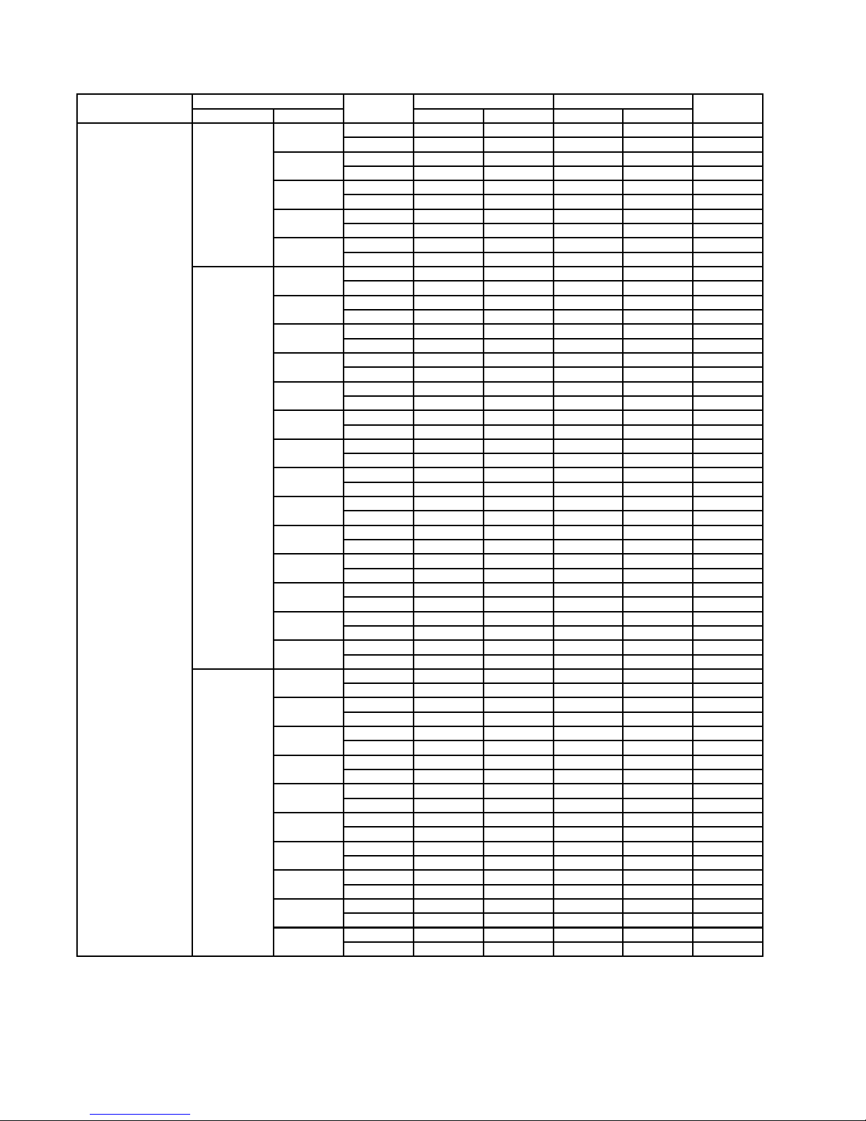
3.5. Outdoor unit: CU-3E18EBE
Outdoor Unit Indoor unit combination Operation
mode
Capacity (kW) Power input (kW) Current (A)
Operation Class (kW) Rating mini - max Rating mini - max
CU-3E18EBE One-room
Operation
2.2 Cooling 2.20 1.8 - 2.9 0.50 0.34 - 0.81 2.5
Heating 3.20 1.2 - 4.1 0.74 0.30 - 1.23 3.7
2.8 Cooling 2.80 1.8 - 2.9 0.70 0.34 - 0.81 3.3
Heating 4.00 1.2 - 4.3 1.05 0.30 - 1.23 5.0
3.2 Cooling 3.20 1.8 - 3.8 0.80 0.34 - 1.36 3.7
Heating 4.50 1.2 - 5.8 1.23 0.30 - 2.10 5.8
4.0 Cooling 4.00 1.8 - 4.3 1.24 0.34 - 1.99 5.6
Heating 5.60 1.2 - 6.8 1.72 0.30 - 2.93 7.7
5.0 Cooling 5.00 1.9 - 5.7 1.55 0.34 - 2.13 6.8
Heating 6.80 1.2 - 6.9 2.10 0.30 - 2.52 9.2
Two-room
Operation
2.2 + 2.2 Cooling 4.40 1.9 - 6.2 1.11 0.35 - 2.10 4.9
Heating 5.80 1.4 - 7.0 1.45 0.31 - 2.55 6.4
2.2 + 2.8 Cooling 5.00 1.9 - 6.2 1.41 0.35 - 2.10 6.2
Heating 6.40 1.4 - 7.0 1.72 0.31 - 2.55 7.6
2.2 + 3.2 Cooling 5.20 1.9 - 6.3 1.49 0.35 - 2.11 6.6
Heating 6.80 1.4 - 7.3 1.84 0.31 - 2.52 8.2
2.2 + 4.0 Cooling 5.20 1.9 - 6.4 1.45 0.35 - 2.11 6.4
Heating 6.80 1.4 - 7.3 1.80 0.31 - 2.51 7.9
2.2 + 5.0 Cooling 5.20 1.9 - 6.8 1.29 0.36 - 2.15 5.7
Heating 6.80 1.4 - 8.0 1.52 0.31 - 2.20 6.7
2.8 + 2.8 Cooling 5.20 1.9 - 6.2 1.54 0.35 - 2.10 6.8
Heating 6.80 1.4 - 7.0 1.93 0.31 - 2.55 8.5
2.8 + 3.2 Cooling 5.20 1.9 - 6.3 1.48 0.35 - 2.11 6.5
Heating 6.80 1.4 - 7.3 1.84 0.31 - 2.52 8.1
2.8 + 4.0 Cooling 5.20 1.9 - 6.4 1.44 0.35 - 2.11 6.4
Heating 6.80 1.4 - 7.3 1.80 0.31 - 2.51 8.0
2.8 + 5.0 Cooling 5.20 1.9 - 6.8 1.29 0.36 - 2.15 5.7
Heating 6.80 1.4 - 8.0 1.52 0.31 - 2.20 6.7
3.2 + 3.2 Cooling 5.20 1.9 - 6.4 1.45 0.35 - 2.12 6.4
Heating 6.80 1.4 - 7.5 1.75 0.31 - 2.49 7.7
3.2 + 4.0 Cooling 5.20 1.9 - 6.5 1.41 0.35 - 2.12 6.3
Heating 6.80 1.4 - 7.5 1.75 0.31 - 2.47 7.8
3.2 + 5.0 Cooling 5.20 1.9 - 6.9 1.25 0.36 - 2.15 5.5
Heating 6.80 1.4 - 8.0 1.50 0.31 - 2.18 6.6
4.0 + 4.0 Cooling 5.20 1.9 - 6.5 1.41 0.35 - 2.12 6.2
Heating 6.80 1.4 - 7.6 1.71 0.31 - 2.47 7.5
4.0 + 5.0 Cooling 5.20 1.9 - 6.9 1.25 0.36 - 2.16 5.5
Heating 6.80 1.4 - 8.0 1.50 0.31 - 2.17 6.6
Three-room
Operation
2.2 + 2.2 +
2.2
Cooling 5.20 1.9 - 7.2 1.24 0.36 - 2.17 5.4
Heating 6.78 1.5 - 8.1 1.53 0.32 - 2.12 6.7
2.2 + 2.2 +
2.8
Cooling 5.20 1.9 - 7.2 1.24 0.36 - 2.17 5.4
Heating 6.80 1.5 - 8.1 1.53 0.32 - 2.12 6.7
2.2 + 2.2 +
3.2
Cooling 5.20 1.9 - 7.2 1.23 0.36 - 2.18 5.4
Heating 6.80 1.4 - 8.3 1.49 0.32 - 2.11 6.5
2.2 + 2.2 +
4.0
Cooling 5.20 1.8 - 7.3 1.23 0.36 - 2.18 5.4
Heating 6.80 1.6 - 8.3 1.46 0.32 - 2.11 6.4
2.2 + 2.8 +
2.8
Cooling 5.20 1.9 - 7.2 1.24 0.36 - 2.17 5.4
Heating 6.80 1.5 - 8.1 1.53 0.32 - 2.12 6.7
2.2 + 2.8 +
3.2
Cooling 5.20 1.9 - 7.2 1.23 0.36 - 2.18 5.4
Heating 6.80 1.4 - 8.3 1.49 0.32 - 2.11 6.5
2.2 + 2.8 +
4.0
Cooling 5.20 1.8 - 7.3 1.22 0.36 - 2.18 5.4
Heating 6.80 1.6 - 8.3 1.42 0.32 - 2.11 6.5
2.2 + 3.2 +
3.2
Cooling 5.20 1.8 - 7.3 1.22 0.36 - 2.18 5.4
Heating 6.80 1.6 - 8.3 1.43 0.32 - 2.10 6.3
2.8 + 2.8 +
2.8
Cooling 5.19 1.9 - 7.2 1.24 0.36 - 2.17 5.4
Heating 6.80 1.5 - 8.1 1.53 0.32 - 2.12 6.7
2.8 + 2.8 +
3.2
Cooling 5.20 1.9 - 7.2 1.23 0.36 - 2.18 5.4
Heating 6.80 1.4 - 8.3 1.49 0.32 - 2.11 6.5
20
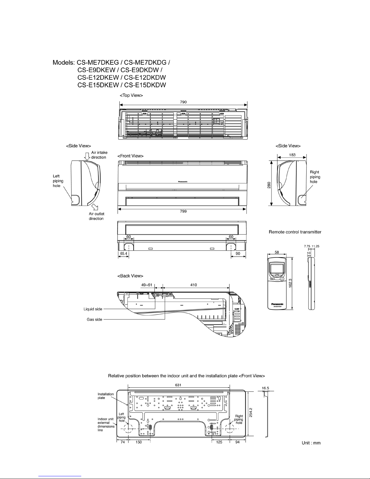
4 Dimensions
4.1. Wall Type
21

22
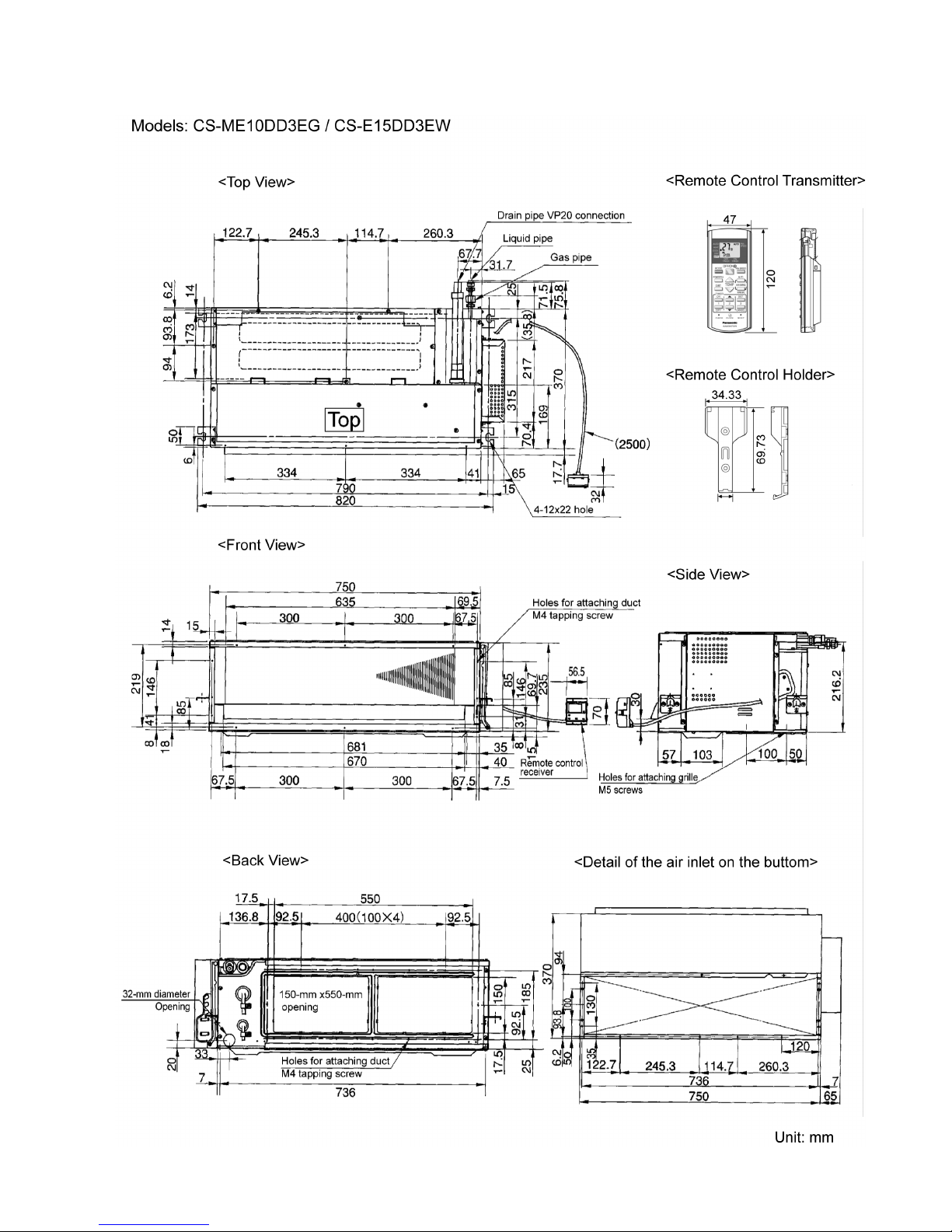
4.2. Duct Type
23
24
4.3. Ceiling Floor Type
25
4.4. Mini-Cassette Type
26
4.5. Outdoor Unit
27
5 Refrigeration Cycle Diagram
28
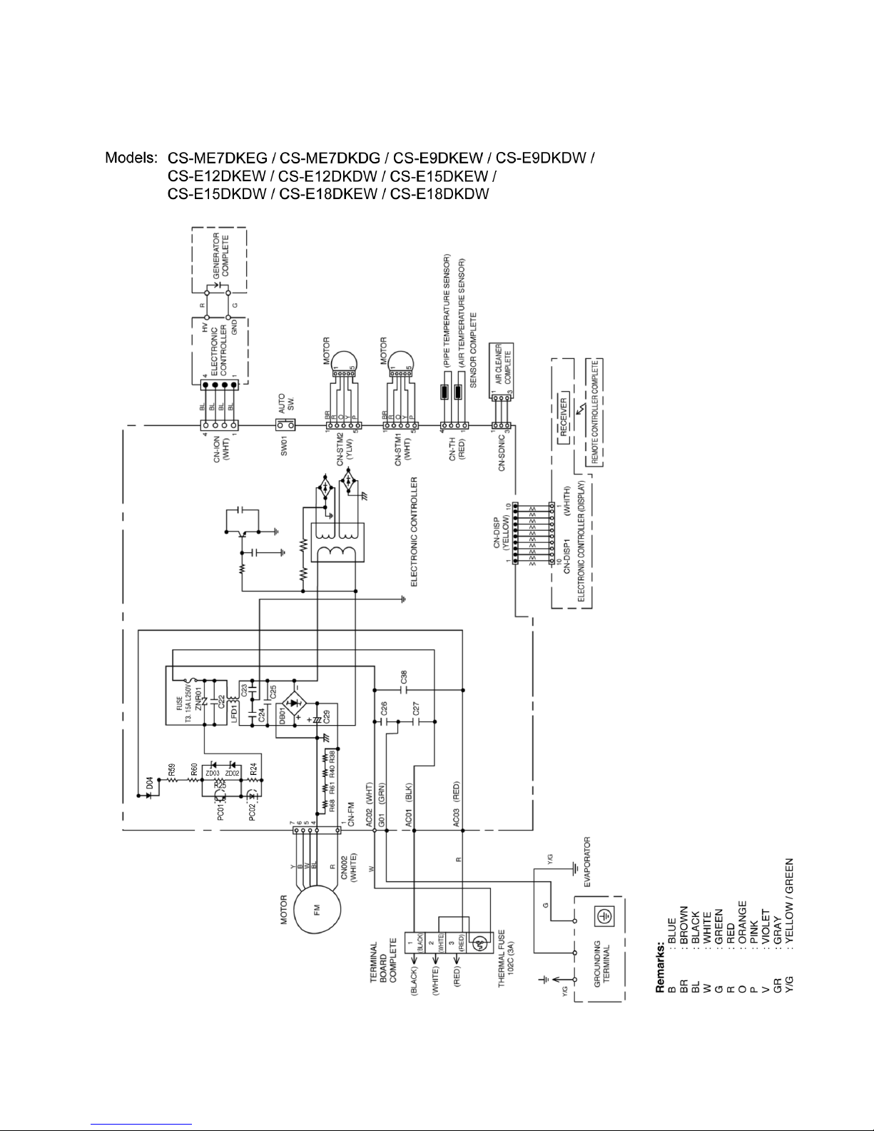
6 Wiring Diagram
6.1. Wall Type
29
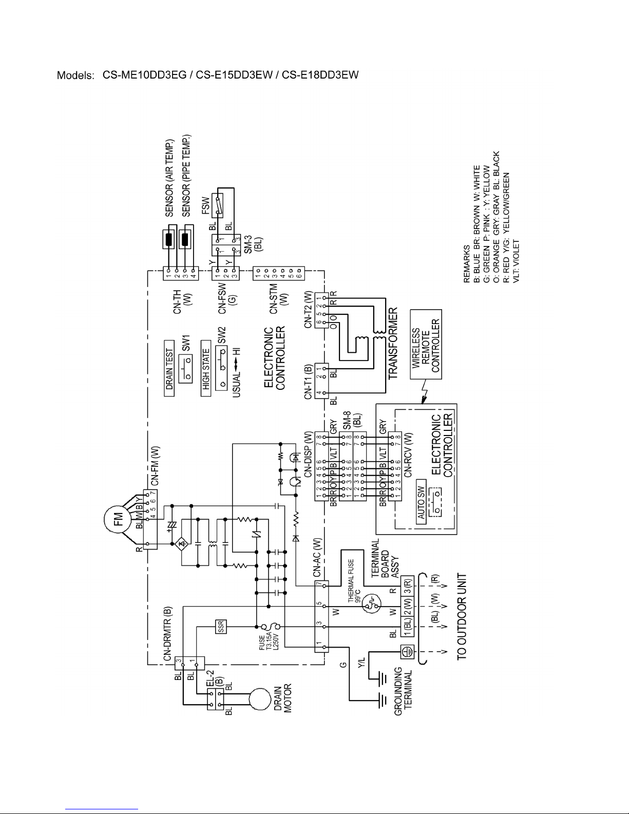
6.2. Duct Type
30
 Loading...