

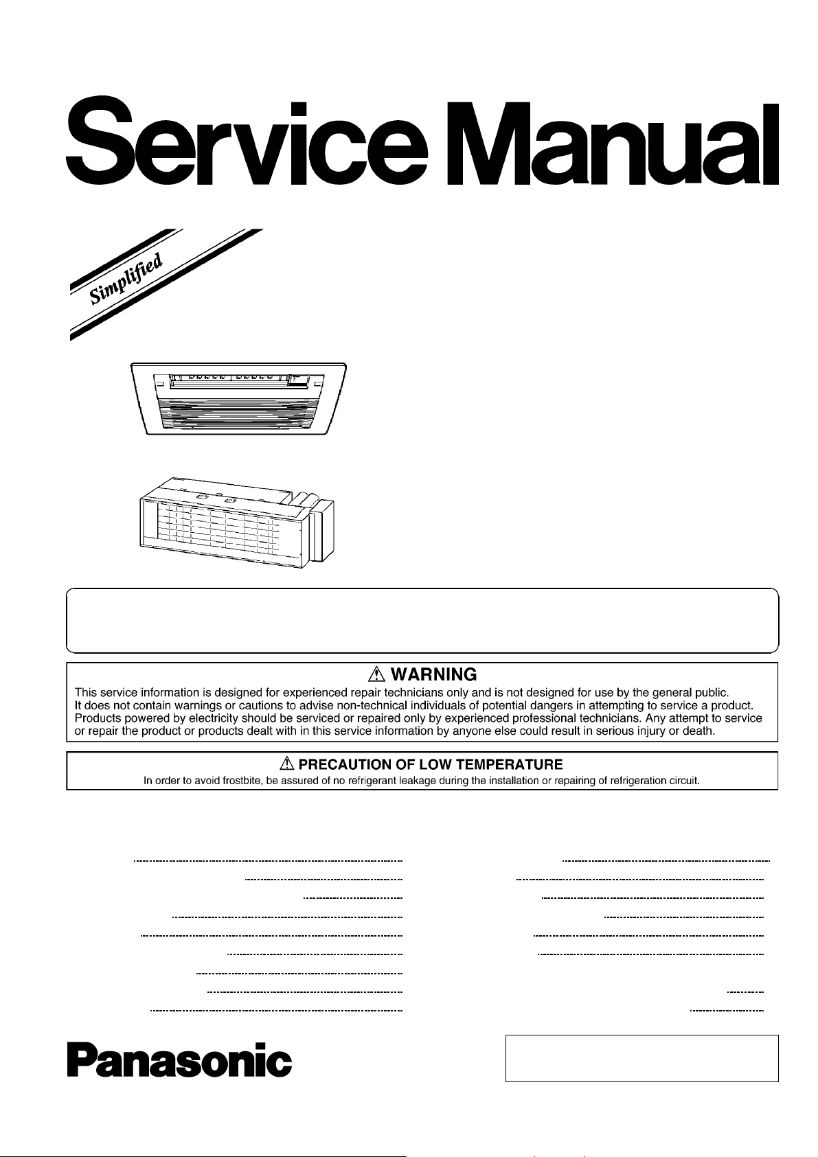
Multi Air Conditioner
CS-ME7CB1P
CS-ME10CB1P
CS-ME12CB1P
CS-ME14CB1P
CS-ME10CD3P
CS-ME14CD3P
ORDER NO. RAC0312001A8
Please file and use this manual together with the service manual for Model No. CS-ME7CKPG, CSME10CKPG, CS-ME12CKPG, CS-ME14CKPG, CS-ME18CKPG, CU-2E15CBPG, CU-2E18CBPG, CU3E23CBPG, CU-4E27CBPG, Order No. RAC0209005C2.
CONTENTS
Page Page
1 Features 3
2 About Lead Free Solder (PbF)
2.1. DISTINCTION OF PbF P.C. BOARD
2.2. CAUTION
3 Functions
3.1. REMOTE CONTROL
3.2. INDOOR UNIT
4 Product Specifications
5 Dimensions
3
3
3
4
4
5
7
8
5.1. Cassette Type 8
5.2. Grille
5.3. Duct Type
6 Refrigeration Cycle Diagram
7 Block Diagram
8 Wiring Diagram
8.1. Cassette Type (CS-
ME7CB1P/ME10CB1P/ME12CB1P/M E14CB1P)
8.2. Duct Type (CS-ME10CD3P/ME14CD3P)
10
11
12
13
14
14
15
© 2003 Matsushita Electric Industrial Co., Ltd. All
rights reserved. Unauthorized copying and
distribution is a violation of law.

CS-ME7CB1P / CS-ME 10CB1P / CS-ME12CB1 P / CS-ME14CB1 P / CS-ME10CD3P / CS-ME14CD3P
9 Operation Details (Functions & Protection) 16
9.1. Simultaneous Operation Control
9.2. Airflow Direction Control (Cassette Type only)
9.3. Indoor Fan Control
9.4. Drain Pump Control
9.5. Auto Restart Control
9.6. Other Indoor Unit Operation Functions
10 Installation Instructions
10.1. Cassette Type
10.2. Duct Type
11 Operating Instructions
12 Disassembly of Parts
16
17
18
20
21
22
30
30
35
41
53
12.1. Cassette Type (Indoor Unit: CS-
ME7CB1P/ME10CB1P/ME12CB1P/M E14CB1P)
12.2. Duct Type (Indoor Unit: CS-ME10CD3P/ME14CD3P)
13 Technical Data
13.1. OPERATION CHARACTERISTICS
14 Electronic Circuit Diagram
14.1. REMOTE CONTROL
14.2. Cassette Type
14.3. Duct Type
15 Exploded View & Replacement Parts List
15.1. CS-ME7CB1P/ME10CB1P/ME12CB1 P/ME14CB1P
15.2. CS-ME10CD3P/ME14CD3P
53
57
59
59
63
63
64
65
66
66
68
2
CS-ME7CB1P / CS-ME 10CB1P / CS-ME12CB1 P / CS-ME14CB1 P / CS-ME10CD3P / CS-ME14CD3P
1 Features
· Product
−
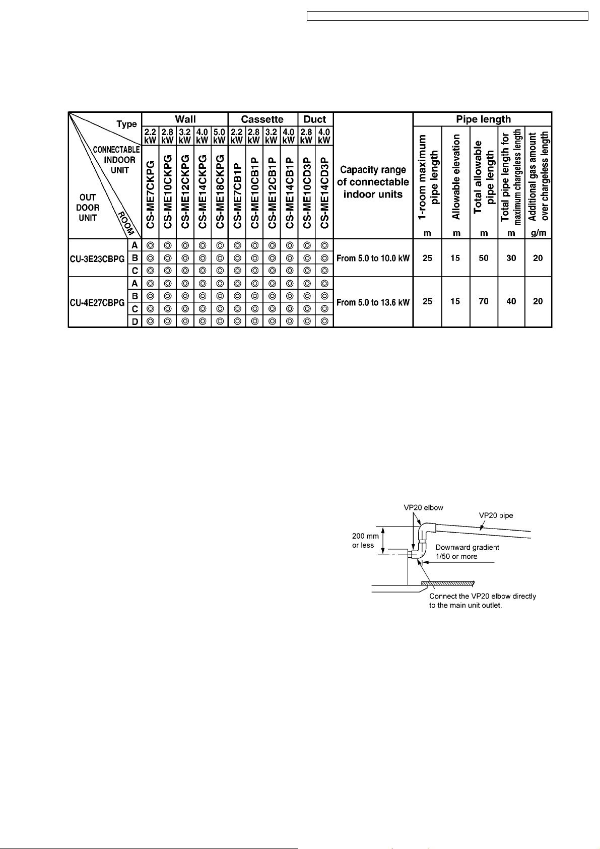
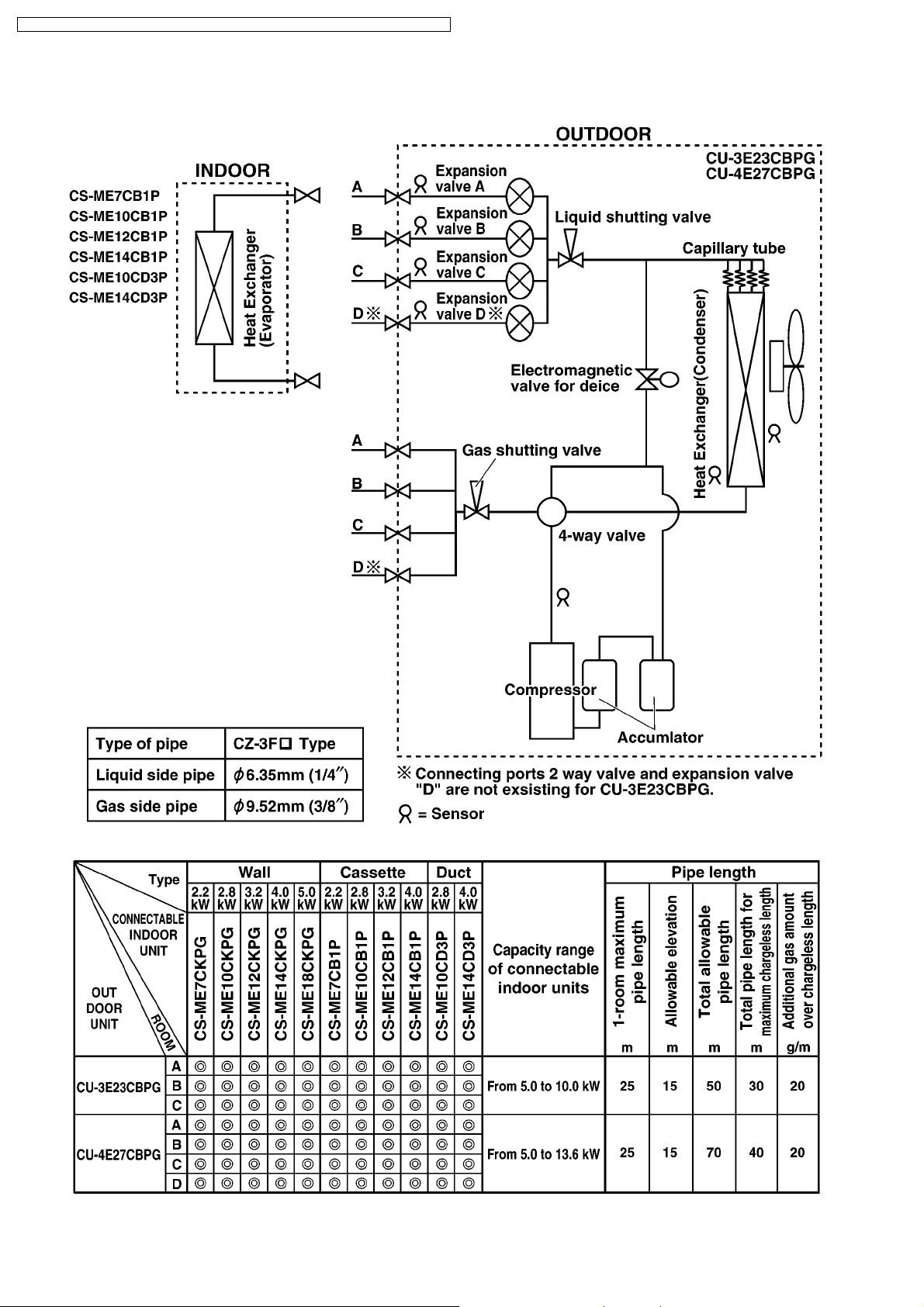
− A single OUTDOOR unit enables air conditioning of up to four separate rooms
− −
Remarks:
1. At least two indoor units must be connected.
2. The total nominal cooling capacity of indoor units that will be connected to outdoor unit must be within connectable
capacity range of outdoor unit. (Shown in the above table)
Example: The below indoor units combination is not possible to connect CU-3E23CBPG. (Total nominal capacity
of indoor unit is between 5.0kW and 10.0kW)
1) Two CS-ME7CB1P only. (Total nominal cooling capacity is 4.4kW)
2) Three CS-ME14CB1P only. (Total nominal cooling capacity is 12.0kW )
−
− Inverter controlled for High energy efficiency and optimal comfort
− −
−
− New refrigerant R410A is used for protecting ozone layer
− −
−
− Lead - free P.C. Board
− −
· Serviceability
−
− Self diagnosis
− −
−
− Test Run at both Cooling and Heating rated frequency
− −
· Built-in drain pump (Cassette and Duct type)
−
− A drain pump is built in.
− −
The pipe can rise to 200 mm above the drain outlet.
2 About Lead Free Solder (PbF)
2.1. DISTINCTION OF PbF P.C. BOARD
P.C. Boards (manufactured) using lead free solder will have a PbF stamp on the P.C. Board.
2.2. CAUTION
· Pb free solder has a higher melting point than standard solder; Typically the melting point is 50 - 70 °F (30 - 40 °C) higher.
Please use a high temperature solder iron and set it to 700 ± 20 °F (370 ± 10 °C).
· Pb free solder will tend to splash when heated too high (about 1100 °F/ 600 °C).
If you must use Pb solder, please completely remove all of the Pb free solder on the pins or solder area before applying Pb
solder. If this is not practical, be sure to heat the Pb free solder until it melts, before applying Pb solder.
3
CS-ME7CB1P / CS-ME 10CB1P / CS-ME12CB1 P / CS-ME14CB1 P / CS-ME10CD3P / CS-ME14CD3P
3 Functions
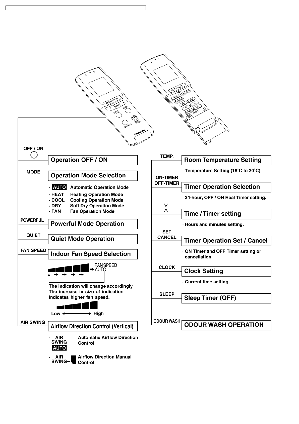
3.1. REMOTE CONTROL
4
3.2. INDOOR UNIT
CS-ME7CB1P / CS-ME 10CB1P / CS-ME12CB1 P / CS-ME14CB1 P / CS-ME10CD3P / CS-ME14CD3P
5
CS-ME7CB1P / CS-ME 10CB1P / CS-ME12CB1 P / CS-ME14CB1 P / CS-ME10CD3P / CS-ME14CD3P
6
4 Product Specifications
CS-ME7CB1P / CS-ME 10CB1P / CS-ME12CB1 P / CS-ME14CB1 P / CS-ME10CD3P / CS-ME14CD3P
Item Cassette Type Duct Type
Power Source Outdoor power (single 230V 50Hz)
Air Volume Cooling m3/min. 9.1 9.6 9.5 7.0 7.8
Noise Level Cooling
Moisture Removal L/h 1.3 1.6 1.8 2.3 1.6 2.3
Refrigeration
piping
Type of Indoor/Outdoor connecting
cable
Drain opening mm VP20
Dimensions mm Height 185 x Width 770 x Depth 360 Height 235 x Width 750
Net Weight kg 9.8 10.5 16.5
Fan Type Cross-flow fan Sirocco fan
Heat exchanger Plate fin forced-draft
Adjustments Switches Wireless remote control
Air filter PP honeycomb -
Connection Liquid mm 6.35 (1/4") Flare to the main unit
Type of pipe CZ-3F
Motor Type DC brushless motor (EHOCM24A4P25) DC brushless motor
Model CS-ME7CB1P CS-ME10CB1P CS-ME12CB1P CS-ME14CB1P CS-ME10CD3P CS-ME14CD3P
Heating m3/min. 9.8 10.2 9.8 8.7
(Power)
Heating
(Power)
Gas mm 9.52 (3/8") Flare to the main unit
Output W 4P 25W 40V A98258 8P 30W 280-340V A981071
Timer Timer with ON and OFF times programmable
Temperature Electronic thermostat
dB(A)
(dB)
dB(A)
(dB)
mm 4 x 1.5 mm2flexible cord, type designation 245 IEC 57 (H05RN-F)
Hi:40(53)
Lo:32(45)
Hi:42(55)
Lo:32(45)
Hi:41(54)
Lo:32(45)
Hi:43(56)
Lo:32(45)
Hi:43(56)
Lo:32(45)
Hi:44(57)
Lo:34(47)
Hi:43(56)
Lo:32(45)
Hi:47(60)
Lo:32(45)
x Depth 370
(ARW31V8P30AC)
Hi:45(58)
Lo:32(45)
Hi:47(60)
Lo:35(48)
Remarks:
The specifications are differ from wall type indoor units when 2.8kW Duct type is connected to CU-2E15CBPG and CU2E18CBPG.
Indoor unit
Combination
Cooling 22 + 28 CU-2E15CBPG 1.39 0.25 - 1.73 6.50
Heating 1.36 0.21 - 1.67 6.05
Cooling 22 + 28 CU-2E18CBPG 1.39 0.25 - 1.73 6.50
Heating 1.36 0.21 - 1.67 6.05
Cooling 28 + 28 (*) 1.56 0.25 - 1.73 7.25
Heating 1.47 0.21 - 1.74 6.50
Cooling 28 + 32 1.67 0.25 - 1.80 7.80
Heating 1.39 0.21 - 1.72 6.15
(*) The combination 2.8kW Duct type X 2 and 2.8kW Duct type + 2.8kW Wall type are same value.
Outdoor unit Power Input (kW) Current (A)
min. - max
* Specifications are subject to change without notice for further improvement.
7
CS-ME7CB1P / CS-ME 10CB1P / CS-ME12CB1 P / CS-ME14CB1 P / CS-ME10CD3P / CS-ME14CD3P9CS-ME7CB1P / CS-ME 10CB1P / CS-ME12CB1 P / CS-ME14CB1 P / CS-ME10CD3P / CS-ME14CD3P
5 Dimensions
5.1. Cassette Type
8
CS-ME7CB1P / CS-ME 10CB1P / CS-ME12CB1 P / CS-ME14CB1 P / CS-ME10CD3P / CS-ME14CD3P
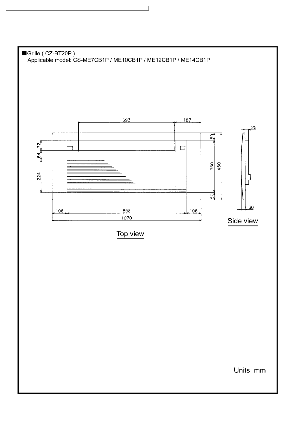
5.2. Grille
10
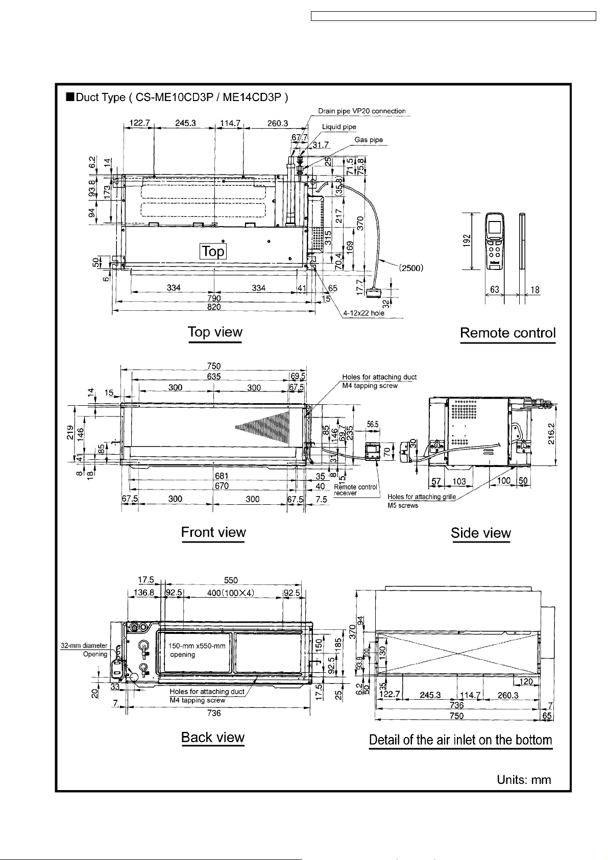
5.3. Duct Type
CS-ME7CB1P / CS-ME 10CB1P / CS-ME12CB1 P / CS-ME14CB1 P / CS-ME10CD3P / CS-ME14CD3P
11
CS-ME7CB1P / CS-ME 10CB1P / CS-ME12CB1 P / CS-ME14CB1 P / CS-ME10CD3P / CS-ME14CD3P
6 Refrigeration Cycle Diagram
12
CS-ME7CB1P / CS-ME 10CB1P / CS-ME12CB1 P / CS-ME14CB1 P / CS-ME10CD3P / CS-ME14CD3P
7 Block Diagram
CS-ME7CB1P/ME10CB1P/ME12CB1P/ME14CB1P/ME10CD3P/ME14CD3P
13
CS-ME7CB1P / CS-ME 10CB1P / CS-ME12CB1 P / CS-ME14CB1 P / CS-ME10CD3P / CS-ME14CD3P
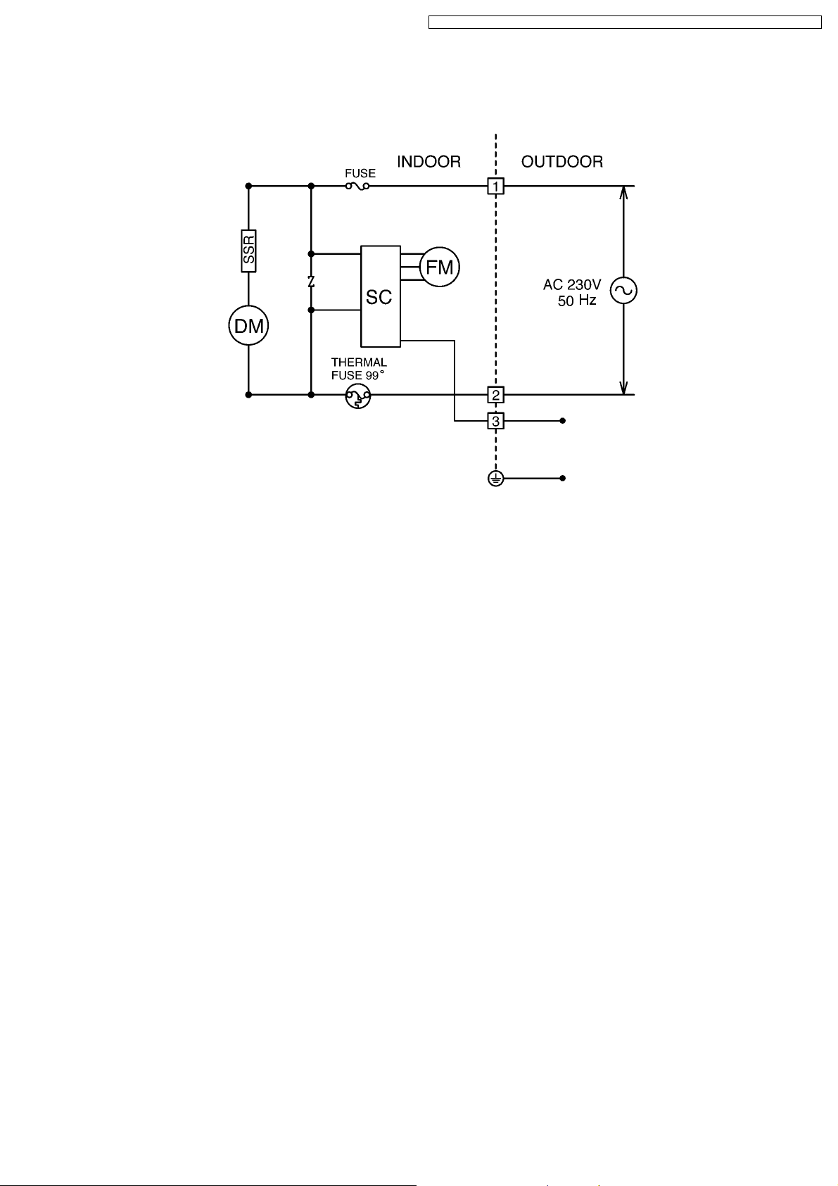
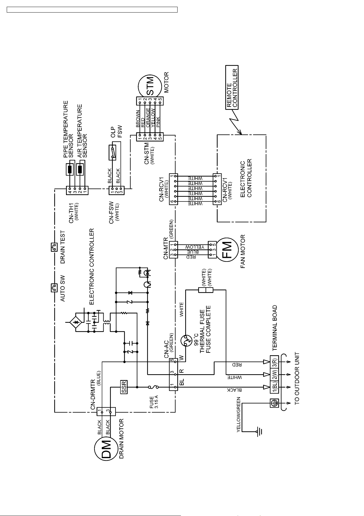
8 Wiring Diagram
8.1. Cassette Type (CS-ME7CB1P/ME10CB1P/ME12CB1P/ME14CB1P)
14
CS-ME7CB1P / CS-ME 10CB1P / CS-ME12CB1 P / CS-ME14CB1 P / CS-ME10CD3P / CS-ME14CD3P
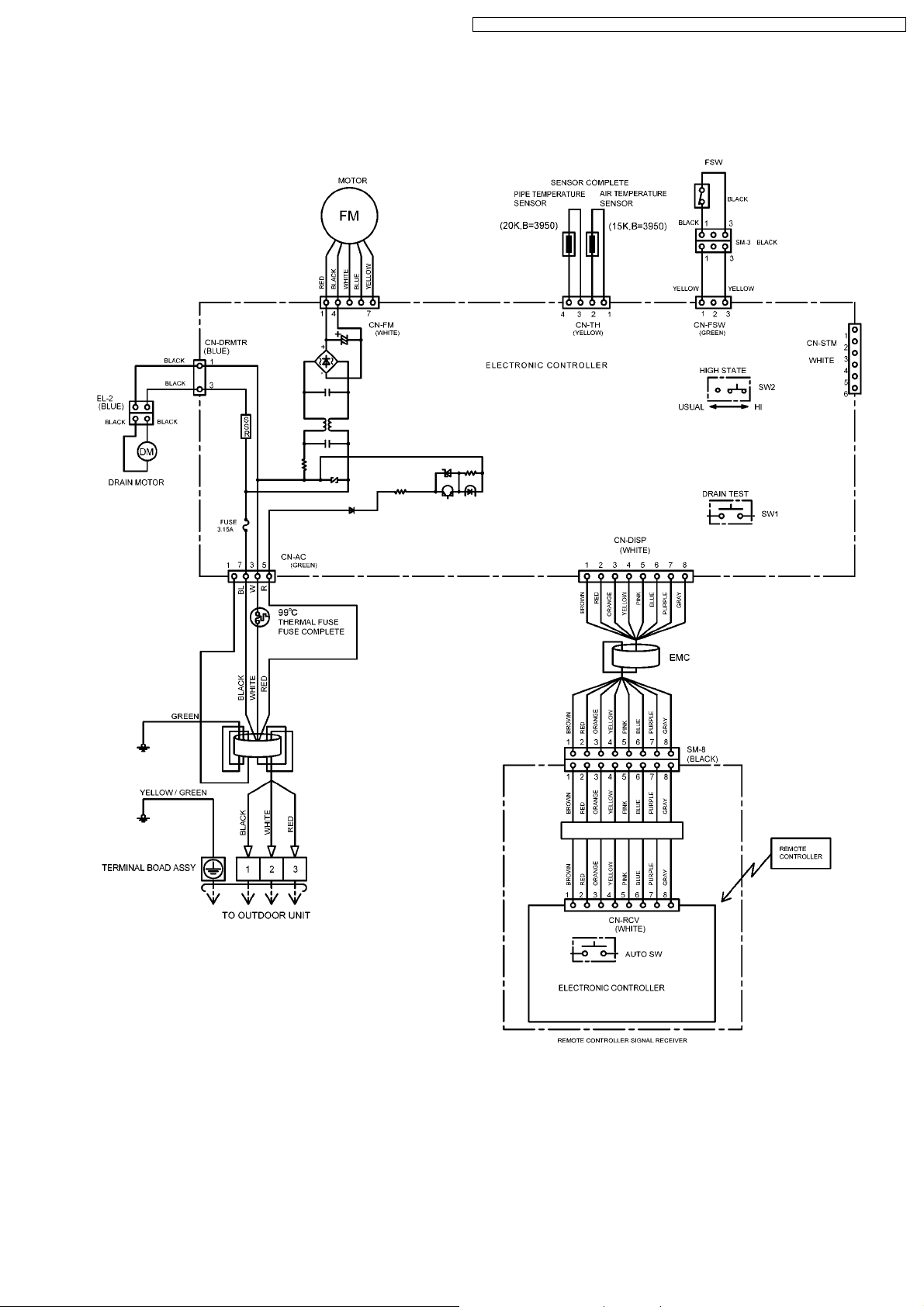
8.2. Duct Type (CS-ME10CD3P/ME14CD3P)
15
CS-ME7CB1P / CS-ME 10CB1P / CS-ME12CB1 P / CS-ME14CB1 P / CS-ME10CD3P / CS-ME14CD3P
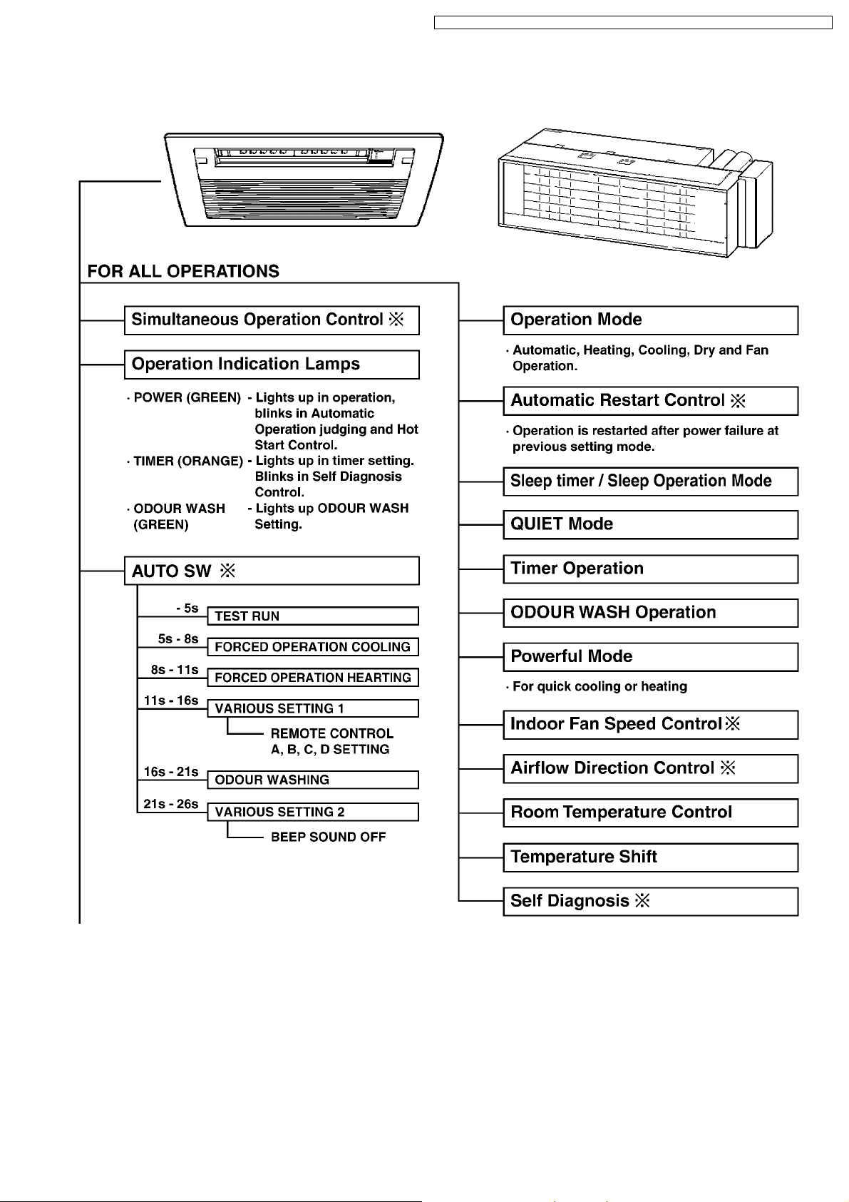
9 Operation Details (Functions & Protection)
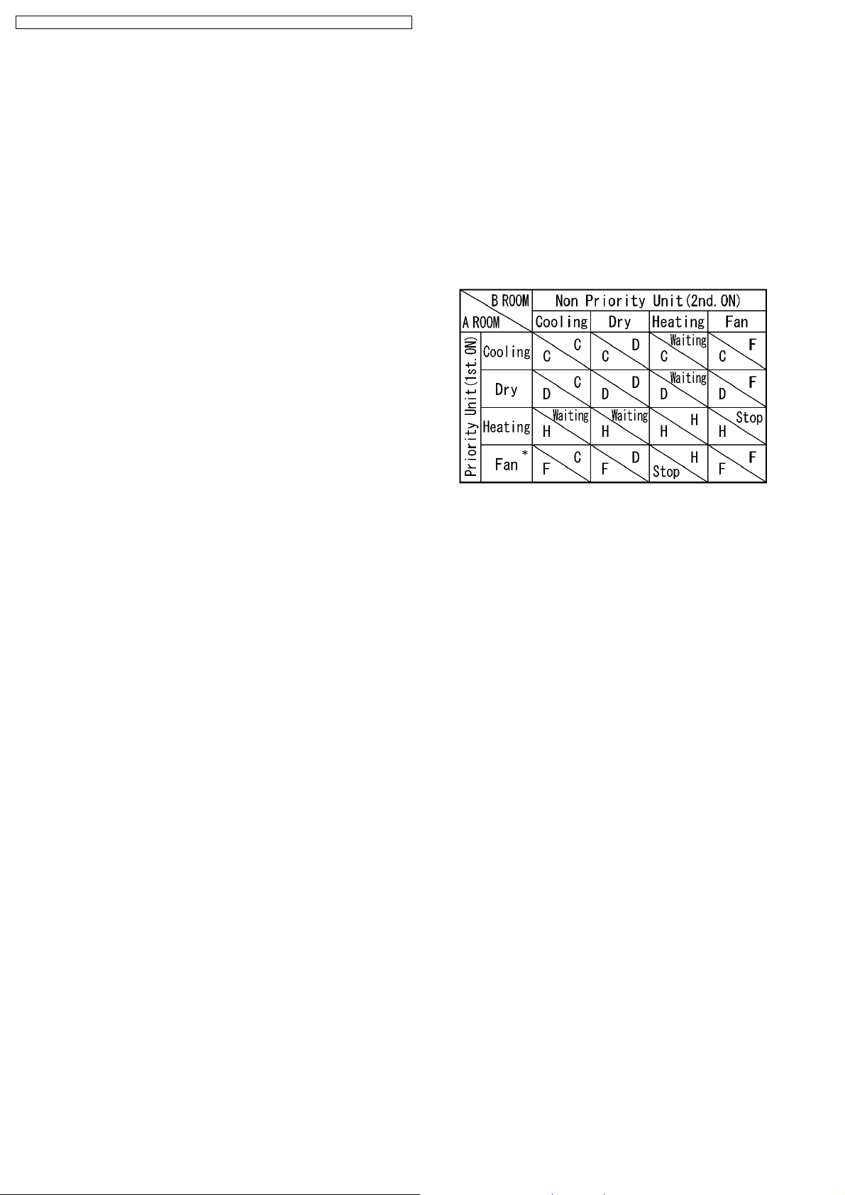
9.1. Simultaneous Operation Control
1. Operation modes which can be selected using the remote
control unit: Automatic, Cooling, Dry, Heating, Fan operation mode.
2. Types of operations modes which can be performed
simultaneously
· Cooling operation and cooling, Dry or fan operation
· Heating operation and heating operation
3. Types of operation modes which cannot be performed
simultaneously
· While a cooling operation is in progress, a heating operation
cannot be performed by an indoor unit in another room.
In the room where the operation button for cooling was pressed
first, the operation is continued. In the room where the operation
button for heating was pressed afterward, the operation lamp of
the indoor unit blinks, where the attempt is made to establish the
heating operation. Its fan is stopped, and the air does not
discharged.
· While a heating operation is in progress, a cooling operation
cannot be performed by an indoor unit in another room.
In the room where the operation button for heating was pressed
first, operation is continued. In the room where the operation
button for cooling was pressed afterward, the operation lamp of
the indoor unit blinks, where the attempt is made to establish the
cooling operation. Its fan is stopped, and the air does not
discharged.
4. Operation mode priority control
· The operation mode designated first by the indoor unit has
priority.
· If the priority indoor unit stops operation or initiates the fan
operation, the priority is transferred to other indoor units.
“Waiting” denotes the standby status in which the operation
lamp LED blinks (ON for 2.5 sec. and OFF for 0.5 sec.), and
the fan is stopped.
* In the fan mode, priority is transferred to a non-priority unit.
Note
C: Cooling operation mode
D: Dry operation mode
H: Heating operation mode
F: Fan operation mode
16
CS-ME7CB1P / CS-ME 10CB1P / CS-ME12CB1 P / CS-ME14CB1 P / CS-ME10CD3P / CS-ME14CD3P
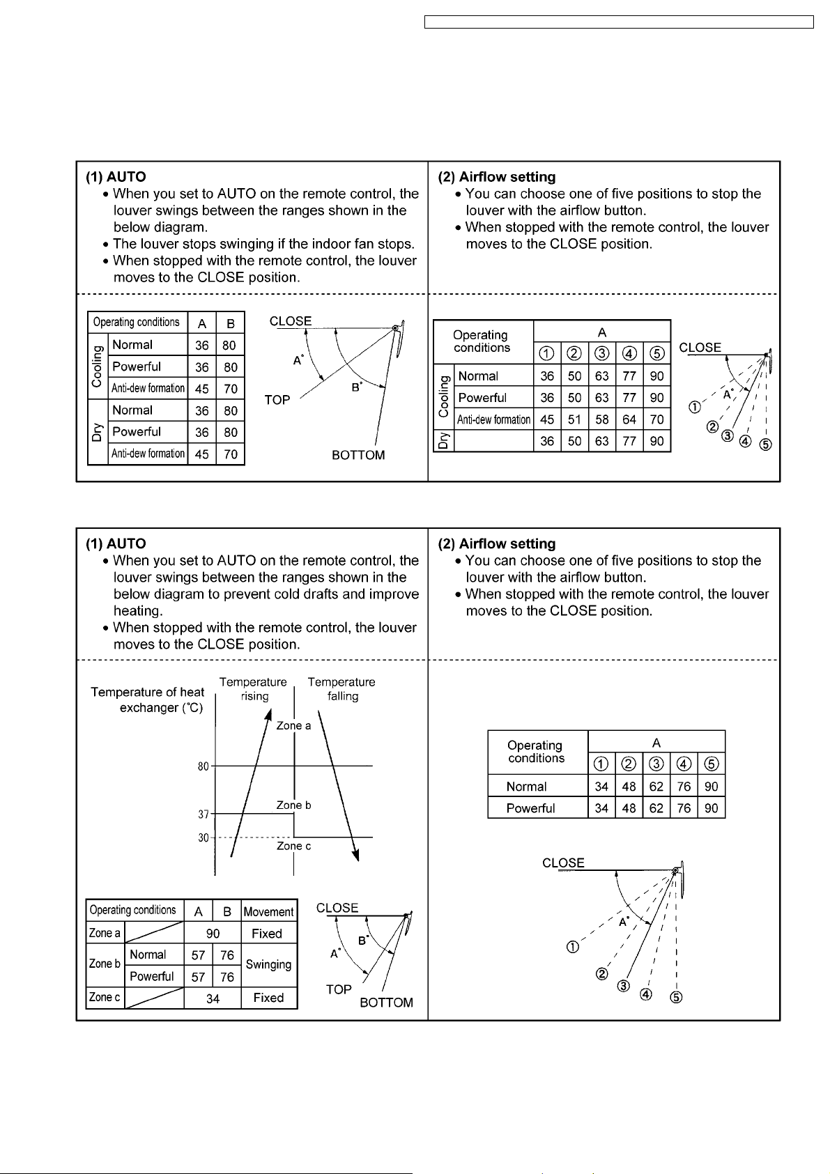
9.2. Airflow Direction Control (Cassette Type only)
The following shows how louver operation changes depending on the direction set with the AIR SWING button and other operating
conditions.
Cooling and Dry
Heating
· The louver stops at the CLOSE position when the power switch or breaker is ON.
· The louver stops at their current position when the power switch or breaker is OFF.
· Move the horizontal airflow direction control louver manually.
17
CS-ME7CB1P / CS-ME 10CB1P / CS-ME12CB1 P / CS-ME14CB1 P / CS-ME10CD3P / CS-ME14CD3P19CS-ME7CB1P / CS-ME 10CB1P / CS-ME12CB1 P / CS-ME14CB1 P / CS-ME10CD3P / CS-ME14CD3P
9.3. Indoor Fan Control
· The following shows how fan speed changes depending on the setting made with the FAN SPEED button and other operating
conditions.
· Actual fan speed may differ from that you set with remote control.
18

CS-ME7CB1P / CS-ME 10CB1P / CS-ME12CB1 P / CS-ME14CB1 P / CS-ME10CD3P / CS-ME14CD3P
9.4. Drain Pump Control
Basic operation
· The drain pump starts 50 seconds after the indoor unit starts or the thermostat comes on (i.e., 10 seconds after the fan
motor starts).
The drain pump stops 30 seconds after the indoor unit stops or the thermostat turns off.
· The drain pump repeats a cycle of on for 30 seconds then off for between 50 and 90 seconds as long as the unit is
operating. Operation while the unit is off is determined by the difference between the temperature setting and the room
temperature.
Float switch operation
· W hen the float switch turns on for 10 seconds continuously, the thermostat of the indoor unit turns off and the drain pump
operates continuously.
· W hen the float switch stays on for 150 seconds continuously, the drain pump and indoor unit stop and the timer lamp
flashes indicating an H21 error.
20
CS-ME7CB1P / CS-ME 10CB1P / CS-ME12CB1 P / CS-ME14CB1 P / CS-ME10CD3P / CS-ME14CD3P
9.5. Auto Restart Control
· if there is a power failure, operation will automatically be restarted when the power is resumed. It will start with the previous
operation mode and airflow direction. (Time Delay Safety Control is valid)
1. Control start conditions
<1> The 24-hour timer must not be set.
<2> The sleep timer must not be set.
Auto restart control is not available when timer or sleep mode is set.
2. Description of control
<1> In the case of manual operation, the operation mode, temperature setting, fan speed and airflow direction before the power
is turned off are restored.
<2> In the case of automatic operation, after the power is restored operation starts with the determination of the mode.
<3> While the air conditioner odour clear timer has been set, the setting is cancelled, and operation is transferred to the mode
before the power is turned off.
<4> While the air conditioner odour clear operation (with timer / without timer setting) are being performed, both of these
operations are completed, and operation is transferred to the operation mode prior to these operations.
Example: When the power is turned off during an outdoor unit cooling operation
21

CS-ME7CB1P / CS-ME 10CB1P / CS-ME12CB1 P / CS-ME14CB1 P / CS-ME10CD3P / CS-ME14CD3P
9.6. Other Indoor Unit Operation Functions
9.6.1. Auto button
Proceed with operation when the air conditioner is stopped.
(When the auto button is pressed during operation, the air conditioner is stopped.)
1. Emergency operation
Press the auto button and release it within 5 seconds to perform emergency operation.
Under normal condition (failure is not occurred) automatic operation is perform ed. In the event of a failure that still enables
operation to be performed, emergency operation is performed.
2. Forced cooling operation
Press the auto button about 5-8 seconds (1 beep sound) to perform the forced cooling operation.
The air conditioner does not operate for 2 minutes if the room temperature is low (intake temperature below 16 °C) so
just wait. The forced operation is performed after the 2 minutes have elapsed.
3. Forced heating operation
Press the auto button about 8-11 seconds (2 beeps sound) to perform the forced heating operation.
4. Setting modes (Remote control transmission code, current switch ing mode)
The remote control transmission code selection mode is established by pressing the AUTO button about 11-16 seconds (3
beeps sound).
22

CS-ME7CB1P / CS-ME 10CB1P / CS-ME12CB1 P / CS-ME14CB1 P / CS-ME10CD3P / CS-ME14CD3P
CHANGING THE REMOTE CONTROL TRANSMISSION CODE
· W hen installing two air conditioners in one room, each air conditioner can be synchronized to the remote control.
In order to operate separately, open the rear cover of one of the remote control and set to “B”.
Set “B” on the remote control.
This can be achieved by cutting the jumper wire of the remote control with a cutter.
Setting the air conditioner unit to “B”
1. Press the “AUTO” button for about 11 to 15 seconds. When you hear three short beeps, release the button.
Note: you will hear one beep in about 5 seconds, and then two beeps in about 8 seconds.
2. Press again the “AUTO” button within 60 seconds. Every press the “AUTO” button, you pressing the “AUTO” button,
which achieves “B” setting.
If you stop pressing the “AUTO” button midway at the short beep, this will achieve “A” setting.
3. After 60 seconds or longer of the above setting, use the “B” set remote control to confirm successful operation.
4. Set, A, B, C or D transmission code at remote control. (Fig.1)
5. Odour clear setting mode
The odour clear inhibit mode is established by pressing the AUTO button 16-21 seconds (4 beeps sound).
6. Individual setting mode
The H14 error detection selection mode is established by pressing the auto button about for 21 seconds (5 beeps sound). Now
remove the remote control unit´s battery cover, and short the “SET” terminals to establish the beep sound mute mode.
* If the auto button is pressed and 26 seconds or so are allowed to elapse, the auto button operation mode is restored.
When nothing happens for 60 seconds in the “Setting mode”, “Odour clear setting mode” or “individual setting mode”
or if a remote control code is received, the mode concerned is canceled.
23

CS-ME7CB1P / CS-ME 10CB1P / CS-ME12CB1 P / CS-ME14CB1 P / CS-ME10CD3P / CS-ME14CD3P
9.6.2. Drain Test (SW1)
When installing the unit and you want the drain pump to operate independently, press the DRAIN TEST switch to operate it for
about 5 minutes.
9.6.3. High Static Pressure Switch (High state switch SW2) (For Duct Type)
To increase the fan speed, open the control box and on the control board switch the HIGH STATE switch (SW2) to “HI”.
24

CS-ME7CB1P / CS-ME 10CB1P / CS-ME12CB1 P / CS-ME14CB1 P / CS-ME10CD3P / CS-ME14CD3P
9.6.4. Self Diagnosis display
The diagnostic displays that appear when trouble has occurred can be checked using the remote control unit.
When trouble occurs, operation is stopped automatically, and the timer lamp blinks. The diagnosis time has been reduced by
warning the user by means of the blinking of the timer lamp.
· When trouble occurs, operation is stopped automatically , and the timer
lamp blinks.
· The timer lamp will go off if the power is turned off, but it will start
blinking again if the air conditioner is operated with the trouble left
unremedied.
· No diagnostic displays will appear when the unit is operated after the
trouble has been remedied. However, the last diagnostic symbol is
stored in the IC´s memory. (This symbol can be cleared.)
· When the air conditioner protection operation is triggered because the
air conditioner is being operated under overload conditions, its heat
radiation is being interfered with or anti-freezing operation is initiated or
because its supply voltage has dropped or its power has been turned
off and then back on during operation, for instance, no diagnostic
displays will appear. However, F99 and other such information are
stored in the IC´s memory: this is normal and not indicative of
malfunctioning.
· The diagnostic displays appear automatically when trouble
occurs.
1. Operation is stopped automatically.
2. The timer lamp of the display unit on the indoor unit blinks.
3. The timer lamp goes off when the power is turned off.
· To display the trouble (or protection operation) status stored in
the memory
1. Turn on the power.
2. Open the remote control unit´s door, and press the timer setting
“UP-ARROW” button for 5 seconds.
3. Press the “UP-ARROW” button slowly and repeatedly until 4 beeps
are heard continuously from the indoor unit.
4. The 3-digit alphanumeric display on the remote control unit
indicates the trouble which has occurred.
* If the 3-digit alphanumeric display on the remote control unit
and the nature of the trouble match, the operation lamp
(green) will light.
· To clear the trouble (or protection operation) status stored in the
memory after remedial action has been taken
1. Set forced cooling operation by pressing Auto button 5 to 8
seconds.
2. Remove the battery cover from remote control.
3. The air conditioner can then be forcibly reset by shorting the
RESET terminals toward the main unit. (one short receiving beep)
The procedure is applied to all of Cassette, Duct and Wall type models.
· Concerning emergency operation (which can be performed in
some of the trouble conditions)
1. Using the remote control unit, select COOL or HEAT, and press
the operation OFF/ON button. (4 receiving beeps are heard, and
the timer lamp blinks.)
2. The air conditioner can now be used temporarily until its trouble is
remedied.
25

CS-ME7CB1P / CS-ME 10CB1P / CS-ME12CB1 P / CS-ME14CB1P / CS-ME10CD3P / CS- ME14CD3P
9.6.4.1. Error Cord
Symbol Diagnosis Diagnosis method
H11 Indoor/Outdoor
abnormal
communication
H12 Indoor unit capacity
unmatched
H14 Intake air temp.
sensor
H16 Outdoor Current
Transformer
H19 Indoor fan motor
mechanism lock
H21 Indoor float switch
abnormality
H23 Indoor heat
exchanger temp.
sensor
H27 Outdoor air temp.
sensor
H28 Outdoor heat
exchanger temp.
sensor 1
This trouble display appears when indoor/outdo or unit communication fails to be established after 30 or more
seconds.
<Diagnosis checkpoint>
1. Measure the voltages of the indoor/outdo or unit communication cables, and check whether the voltage is
being supplied properly to the outdoor unit or whether it is being returned from the outdoor unit to the
indoor units.
This trouble display appears when wrong in the total connection capacity and wrong connection in each
capacity.
The trouble is determined within 2 minutes after the power is turned on.
<Diagnosis checkpoint>
1. Check the total capacity of the units connected and check that the models are compatible for connection.
This trouble display appears when the intake air temperature has exceeded above 46 °C continuously for 2
minutes or dropped below -54 °C continuously for 5 seconds during operation.
<Diagnosis checkpoint>
1. This trouble display appears when a temperature which is impossibly high or low from a normal standpoint
has been detected.
Check the sensor, and if open-circuiting (more than 500 kΩ) or short-circuiting (less than 6.5 kΩ) is not
found, defective contact of the connector is to blame.
When the total current has dropped below the set current level continuously for 20 seconds during operation
beyond the set capacity, operation is stopped. Three minutes later, operation is started up again, and when the
trouble occurs on 4 successive occasions, the trouble display appears (the timer lamp blinks).
<Diagnosis checkpoint>
1. Check the refrigerating cycle: Gas may be leaking (the amount of refrigerant is extremely low).
2. Check the control P.C. Board: Check for a broken wire (open circuit) in the current transformer. (If an open
circuit is found, replace the control P.C. Board.)
In the case of a scroll compressor (DC motor), H16 is detected only when the regular compressor is
operating.
· High-voltage PWM: When a state in which the fan motor speed is not synchronized with the control signal
has been detected on 7 successive occasions:
· Low-voltage PAM: When the fan lock detection signal has been detected on 7 successive occasions or it
has been detected continuously for 25 seconds or when a state in which the fan motor speed is not
synchronized with the control signal has been detected on 7 successive occasions:
The trouble display appears (the timer lamp blinks).
<Diagnosis checkpoint>
1. Check the nature of the fan lockup trouble.
2. Check for disconnections of the fan motor connectors and for defects in contact, in the fan motor and in
the control P.C. Board.
Error appears when the float switch is open for 150 seconds.
<Diagnosis checkpoint>
1. Drain blockage
2. Check the conductivity of float switch.
3. Check that the resistance of the drain motor is about 200 Ω
This trouble display appears when a temperature of under approximately -40 °C or above approximately 80 °C
has been detected by the heat exchanger temperature sensor continuously for 5 seconds.
(This trouble is not detected during de-icing.)
<Diagnosis checkpoint>
1. This trouble display appears when a temperature which is impossibly high or low from a normal standpoint
has been detected.
Check the sensor, and if open-circuiting (more than 500 kΩ) or short-circuiting (less than 2.5 kΩ) is not
found, defective contact of the connector or a defective control P.C. Board is to blame.
This trouble display appears when a temperature of under approximately -40 °C or above approximately 150
°C has been detected by the outside air temperature sensor for 2 to 5 seconds. (This trouble is not detected
during de-icing.)
<Diagnosis checkpoint>
1. This trouble display appears when a temperature which is impossibly high or low from a normal standpoint
has been detected.
Check the sensor, and if open-circuiting (more than 500 kΩ or short-circuiting (less than 0.5 kΩ) is not
found, defective contact of the connector or a defective control P.C. Board is to blame.
This trouble display appears when a temperature of under approximately -60 °C or above approximately 110
°C has been detected by the heat exchanger temperature sensor for 2 to 5 seconds. (This trouble is not
detected during de-icing.)
<Diagnosis checkpoint>
1. This trouble display appears when a temperature which is impossibly high or low from a normal standpoint
has been detected.
Check the sensor, and if open-circuiting (more than 500 kΩ) or short-circuiting (less than 0.5 kΩ) is not
found, defective contact of the connector or a defective control P.C. Board is to blame.
26

CS-ME7CB1P / CS-ME 10CB1P / CS-ME12CB1 P / CS-ME14CB1P / CS-ME10CD3P / CS- ME14CD3P
Symbol Diagnosis Diagnosis method
H30 Outdoor discharge
pipe temp. sensor
Disconnected discharge sensor
· When the condensation temperature is higher than the discharge temperature + (plus) 6 °C, a sensor
disconnection is detected, operation stops, and the trouble display appears (the timer lamp blinks).
<Diagnosis checkpoint>
1. This trouble display appears when a temperature which is impossibly high or low from a normal standpoint
has been detected.
Check the sensor, and if open-circuiting (more than 500 kΩ) or short-circuiting (less than 0.5 kΩ) is not
found, defective contact of the connector or a defective control P.C. Board is to blame.
H32 Outdoor heat
exchanger temp.
sensor 2
(discharge pipe
temp.)
This trouble display appears when a temperature of under approximately -60 °C or over approximately 110 °C
has been detected continuously for 2 to 5 seconds by the outlet temperature sensor of the heat exchanger.
<Diagnosis checkpoint>
1. This trouble display appears when a temperature which is impossibly high or low from a normal standpoint
has been detected.
Check the sensor, and if open-circuiting (more than 500 kΩ) or short-circuiting (less than 0.5 kΩ) is not
found, defective contact of the connector or a defective control P.C. Board is to blame.
H34 Outdoor heat sink
temp. sensor
This trouble display appears when a temperature of under -43 °C or above 80 °C has been detected by the
outdoor unit radiator fin sensor continuously for 2 seconds.
<Diagnosis checkpoint>
1. This trouble display appears when a temperature which is impossibly high or low from a normal standpoint
has been detected.
Check the sensor, and if open-circuiting (more than 500 kΩ) or short-circuiting (less than 0.5 kΩ) is not
found, defective contact of the connector or a defective control P.C. Board is to blame.
H35 Drainage or drain
pump abnormality
This error appears if the float switch is open three times for ten seconds or more during a twenty-minute
period.
<Diagnosis checkpoint>
1. Drain blockage
2. Check the conductivity of float switch.
3. Check that the resistance of the drain motor is about 200 Ω
H36 Outdoor gas pipe
temp. sensor
This trouble display appears when a temperature of under approximately -45 °C or above approximately 149
°C has been detected by the outdoor unit gas side pipe temperature sensor continuously for 2 to 5 seconds.
<Diagnosis checkpoint>
1. This trouble display appears when a temperature which is impossibly high or low from a normal standpoint
has been detected.
Check the sensor, and if open-circuiting (more than 500 kΩ) or short-circuiting (less than 0.5 kΩ) is not
found, defective contact of the connector or a defective control P.C. Board is to blame.
H37 Outdoor liquid pipe
temp. sensor
This trouble display appears when a temperature of under -45 °C or above 149 °C has been detected by the
outdoor unit liquid side pipe temperature sensor continuously for 2 seconds.
<Diagnosis checkpoint>
1. This trouble display appears when a temperature which is impossibly high or low from a normal standpoint
has been detected.
Check the sensor, and if open-circuiting (more than 500 kΩ) or short-circuiting (less than 0.5 kΩ) is not
found, defective contact of the connector or a defective control P.C. Board is to blame.
H39 Abnormal indoor
operating unit or
standby units
H41 Abnormal wiring or
piping connection
This display appears in rooms other than one in which indoor freezing trouble has occurred when the pipes
have been connected incorrectly, when an outdoor expansion valve is defective or when an expansion valve
connector has become disconnected .
CU-2E only
This display appears when this kind of trouble is detected 3 minutes after a forced cooling operation was
conducted for one room during the initial operation after the power was turned on. It appears when:
· The indoor unit pipe temperature in a room without the capacity supply available at an outside air
temperature above 5 °C has dropped by more than 20 °C to 5 °C or lower 3 minutes after the compressor
started up.
· The outdoor unit gas pipe temperature in a room without the capacity supply available has dropped by
more than 5 °C to 5 °C or lower 3 minutes after the compressor started up.
H97 Outdoor fan motor
mechanism lock
When the fan motor speed detected when its maximum output is demanded is below 30 rpm continuously for
15 seconds, the fan motor stops for 3 minutes and then restarted.
When this happens on 16 occasions (the trouble display is cleared when the value is normal for 5 minutes),
the H97 diagnostic symbol is stored in the memory, and the fan motor stops.
<Diagnosis checkpoint>
1. Check the nature of the fan lockup trouble.
2. Check for disconnections of the fan motor connectors and for defects in contact, in the fan motor and in
the control P.C. Board.
H98 Indoor high pressure
protection
The restriction on the compressor frequency is started when the temperature of the indoor unit heat exchanger
source is between 50 °C and 52 °C, the compressor stops at a temperature from 62 °C to 65 °C, it is restarted
3 minutes later at below 62 °C to 65 °C, and the restriction on the compressor frequency is released at a
temperature between 48 °C and 50 °C. (No trouble display appears.)
<Diagnosis checkpoint>
1. Check the indoor unit heat exchanger temperature sensor (check for changes in its characteristics and
check its resistance): Symptoms include no hot start when operation is started, a failure of the thermostat
to turn on (no outdoor unit operation). And frequent repetition of stopping and startup.
2. Check also for short circuits indoors and clogging of the air filters.
27
CS-ME7CB1P / CS-ME 10CB1P / CS-ME12CB1 P / CS-ME14CB1P / CS-ME10CD3P / CS- ME14CD3P
Symbol Diagnosis Diagnosis method
H99 Indoor operating unit
freezing
The restriction on the compressor frequency is started when the indoor unit heat exchanger temperature is
between 8 °C and 12 °C. Operation stops if a temperature below 0 °C continues for 6 minutes. Three minutes
later, operation is started up at a temperature from 3 °C to 8 °C. The restriction on the compressor frequency
is released at a temperature between 13 °C and 14 °C.
<Diagnosis checkpoint>
1. A cooling or dry mode operation conducted at a low outside air temperature is mainly to blame:
this is not indicative of any malfunctioning.
If the outside air temperature rises during automatic operation in the winter months, the dry mode
operation is selected. The H99 diagnostic display also appears at such a time.
2. Check the refrigerating cycle: Gas may be leaking (the amount of refrigerant is low) or a pipe may be
broken, etc.
3. Check also for short circuits indoors and clogging of the air filters.
F11 4-way valve switching
failure
When a difference of 0 °C to 5 °C has been detected between the outdoor unit heat exchanger temperature
and liquid side pipe temperature on 5 occasions, the trouble display appears.
<Diagnosis checkpoint>
1. Check the 4-way valve coil: Check that no power is supplied to the coil during cooling and dry mode
operations, and that power is supplied during heating operations. Inspect the coil for broken wires (open
circuits).
2. If the coil is trouble-free, the switching action of the 4-way valve may be defective.
F17 Indoor standby units
freezing
When the difference of an intake temperature (room temperature sensor) and the indoor unit heat exchanger
temperature (piping sensor) is higher than 10 °C or an indoor unit heat exchanger temperature of below -1 °C
has been detected continuously for 5 minutes, operation stops. Three minutes later, it is started up, and the
trouble display appears when this has occurred on 3 consecutive occasions.
<Diagnosis checkpoint>
1. Check the refrigerating cycle: Expansion valve leakage
2. Check the indoor unit pipe temperature sensor (check for changes in its characteristics and check its
resistance).
F90 PFC circuit protection When a DC voltage over 393V to 424V has been detected on 16 occasions, this trouble display appears.
<Diagnosis checkpoint>
1. To check whether the shutting valve has been left close by mistake, operation is performed for one to
several minutes after the compressor has started up, F93 is stored in the memory as the symptom, and
operation stops.
2. Check the inverter circuit (for open circuits) in the control P.C. Board: Check the IPM base current (6
locations) within 3 minutes after the power has been turned back on. As the symptom, F93 is stored in the
memory 30 seconds after the compressor has started up, and operation stops. The trouble display
appears after 4 restarts.
3. Check for broken wires (open circuits) in the compressor winding: Approximately 1 ohm under normal
conditions for each phase (same symptom as in 2.)
4. Check the power supply voltage has been fluctuating or not.
F91 Refrigeration cycle
abnormality
When the compressor frequency is above 55 Hz and the current drops below the prescribed level continuously
for 7 minutes, operation stops, and it is restarted 3 minutes later.
When the compressor discharge temperature has exceeded the setting and the expansion valve has remained
fully open for 80 seconds, operation stops, and it is restarted 3 minutes later.
When the stopping described above has occurred on 4 occasions, operation stops, and the trouble display
appears.
<Diagnosis checkpoint>
1. Check the refrigerating cycle: Gas may be leaking (more than one-half of the volume of the gas has gone).
The diagnostic displays resulting from a gas leak generally change in the following sequence depending
on the extent of the gas leak: H99 → F97 → F91 → H16.
The range of this trouble (F91) is limited. (Compressor protection at the start of the season)
F93 Compressor
abnormal revolution
When a state in which the rotation of the compressor is not synchronized with the control signal has been
detected on 8 successive occasions, operation stops, and the trouble display appears.
<Diagnosis checkpoint>
1. To check whether the shutting valve has been left close by mistake, operation is performed for one to
several minutes after the compressor has started up, F93 is stored in the memory as the symptom, and
operation stops.
2. Check the inverter circuit (for open circuits) in the control P.C. Board: Check the IPM base current (6
locations) within 3 minutes after the power has been turned back on. As the symptom, F93 is stored in the
memory 30 seconds after the compressor has started up, and operation stops. The trouble display
appears after 4 restarts.
3. Check for broken wires (open circuits) in the compressor winding: Approximately 1 ohm under normal
conditions for each phase (same symptom as in 2.)
F95 Outdoor high
pressure protection
CU-2E only
When the temperature of the outdoor unit heat exchanger temperature sensor exceeds 62 °C, the F95
diagnostic symbol is stored in the memory, and operation stops. 13 minutes later, operation is restarted at a
temperature below 48 °C. This trouble display appears when this happens on 4 occasions in a 20-minute
period.
<Diagnosis checkpoint>
1. Check the outdoor unit heat exchanger temperature sensor (check for changes in its characteristics and
check its resistance).
2. Check whether something is interfering with the dissipation of the heat outdoors.
28

CS-ME7CB1P / CS-ME 10CB1P / CS-ME12CB1 P / CS-ME14CB1P / CS-ME10CD3P / CS- ME14CD3P
Symbol Diagnosis Diagnosis method
F96 IPM (Power transistor
module) or
compressor
overheating
When this trouble is detected from the electrical parts radiation fin temperature sensor and OLP output during
operation, operation stops, and it is restarted 3 minutes later. If the trouble occurs on 4 occasions, operation
stops, and the trouble display appears.
<Diagnosis checkpoint>
1. Something may be interfering with the dissipation of the heat outdoors or the outdoor unit fan may be
defective. (The outdoor unit fan is not running.)
2. Defective IPM (outdoor unit control P.C. Board)
3. Gas leaks. Shutting valve is not opened.
F97 Compressor high
discharge
temperature
This trouble display appears and operation stops when this happens on 6 occasions (it is cleared when the
operation is normal for 20 minutes).
<Diagnosis checkpoint>
1. Check the refrigerating cycle: Gas may be leaking (the amount of refrigerant is low). The stopping of the
outdoor unit from time to time is a symptom of this trouble.
2. When operation steps with this trouble display appearing, check the compressor temperature sensor
(check for changes in its characteristics and check its resistance).
3. Something may be interfering with the dissipation of the heat outdoors or the outdoor unit fan may be
defective. (The fan will not run because of an open circuit.)
(The protection function may be activated by an overload, and the F97 trouble display will remain stored
in the memory.)
F98 Total running current
protection
When the total current exceeds the setting (17A to 20A), frequency control is started, and if it then exceeds the
setting, operation stops, and the trouble display appears.
<Diagnosis checkpoint>
1. Check the AC voltage at the outdoor unit terminal board during operation: The voltage drop must be within
5% of the voltage when operation has stopped (± 110% of rated voltage even during operation). If the
voltage drop exceeds 5% or if the voltage changes suddenly, inspect whether the power supply cord and
indoor/outdoor unit connection cables are too long or too small in diameter, etc.
2. Check whether something is interfering with the dissipation of the heat outdoors (during cooling
operations): Normally, the capacity is limited by the current so that the outdoor unit don’t stop, and the
diagnostic display does not appear.
F99 DC peak detection When “Output current trouble”, which occurs when the prescribed current level is exceeded, has occurred on
16 consecutive occasions, operation stops, and the trouble display appears.
<Diagnosis checkpoint>
1. Check whether the compressor is defective (locked up or shorted winding). Check the outdoor unit control
P.C. Board.
29

10 Installation Instructions
10.1. Cassette Type
Installation Instructions
CS-ME7C B1P / CS-ME10CB1 P / CS-ME 12CB1P / CS-ME14CB1 P / CS-ME 10CD3P / CS-ME14 CD3P
30
Required tools for Installation Works
1. Philips screw driver
2. Level gauge
3. Electric drill, hole core drill
(ø70 mm)
4. Hexagonal wrench (4 mm)
5. Spanner
6. Pipe cutter
7. Reamer
8. Knife
9. Gas leak detector
10. Measuring tape
11. Thermometer
12. Megameter
13. Multimeter
SAFETY PRECAUTIONS
• Read the following “SAFETY PRECAUTIONS” carefully before installation.
• Electrical work must be installed by a licensed electrician. Be sure to use the correct rating of the power plug and main
circuit for the model to be installed.
• The caution items stated here must be followed because these important contents are related to safety. The meaning of
each indication used is as below. Incorrect installation due to ignoring of the instruction will cause harm or damage, and the
seriousness is classified by the following indications.
WARNING
CAUTION
The items to be followed are classified by the symbols:
• Carry out test running to confirm that no abnormality occurs after the installation. Then, explain to user the operation,
care and maintenance as stated in instructions. Please remind the customer to keep the operating instructions for future
reference.
This indication shows the possibility of causing death or serious injury.
This indication shows the possibility of causing injury or damage to properties only.
Symbol with background white denotes item that is PROHIBITED from doing.
14. Torque wrench
18 N•m (1.8 kgf.m)
42 N•m (4.2 kgf.m)
15. Vacuum pump
16. Gauge manifold
WARNING
1) Engage dealer or specialist for installation. If installation done by the user is defective, it will cause water leakage,
electrical shock or fire.
2) Install according to this installation instruction strictly. If installation is defective, it will cause water leakage, electrical
shock or fire.
3) Use the attached accessories parts and specified parts for installation. Otherwise, it will cause the set to fall, water leakage,
fire or electrical shock.
4) Install at a strong and firm location which is able to withstand the set's weight. If the strength is not enough or
installation is not properly done, the set will drop and cause injury.
5) For electrical work, follow the local national wiring standard, regulation and this installation instruction. An independent
circuit and single outlet must be used. If electrical circuit capacity is not enough or defect found in electrical work, it will
cause electrical shock or fire.
6) Use the specified cable (1.5 mm
7) Wire routing must be properly arranged so that control board cover is fixed properly. If control board cover is not fixed
8) When carrying out piping connection, take care not to let air substances other than the specified
8) Otherwise, it will cause lower capacity, abnormal high pressure in the refrigeration cycle, explosion and
9) When connecting the piping, do not allow air or any substances other than the specified refrigerant
10) Do not modify the length of the power supply cord or use of the extension cord, and do not share the
externa
so that no
connection.
perfectly, it will cause heat-up at connection point of terminal, fire or electrical shock.
refrigerant go into refrigeration cycle.
injury.
(R410A) to enter the refrigeration cycle. Otherwise, this may lower the capacity, cause abnormally high
pressure in the refrigeration cycle, and possibly result in explosion and injury.
single outlet with other electrical appliances. Otherwise, it will cause fire or electrical shock.
l force will be acted on the terminal. If connection or fixing is not perfect, it will cause heat-up or fire at the
2
) and connect tightly for indoor/outdoor connection. Connect tightly and clamp the cable
CAUTION
1) This equipment must be earthed. It may cause electrical shock if grounding is not perfect.
2) Do not install the unit at place where leakage of flammable gas may occur. In case gas leaks and
accumulates at surrounding of the unit, it may cause fire.
3)
Carry out drainage piping as mentioned in installation instructions. If drainage is not perfect, water may enter the room and
damage the furniture.
ATTENTION
1) Selection of the installation location.
1) Select a installation location which is rigid and strong enough to support or hold the unit, and select a location for easy
maintenance.
2) Do not release refrigerant.
3) Do not release refrigerant during piping work for installation, reinstallation and during repairing a refrigeration parts. Take
care of the liquid refrigerant, it may cause frostbite.
3) Installation work.
4) It may need two people to carry out the installation work.
4) Do not install this appliance in a laundry room or other location where water may drip from the ceiling, etc.

31
Indoor Unit Accessory Parts
No. No. No.
Accessory part Accessory part Accessory part
Piping insulation
1
Band
2
Remote control
3
Selecting the Installation Location
1
Determine the location with the agreement of the customer.
Indoor unit
The location should be strong enough to support the main unit without vibration.
There should not be any heat or steam sources nearby.
Drainage should be easy. Avoid locating the drain port close to ditches
(domestic wastewater).
Avoid locations above entrances and exits.
Ensure the distances indicated by the marks in the illustration.
Ensure sufficient space for installation and servicing.
The ceiling surface (lower surface) should be level.
Locate the indoor unit at least 1 m or more away from a TV, radio, wireless
equipment, antenna cables and fluorescent lights, and 2 m or more away
from a telephone.
Note that if the air conditioning unit is installed near an electronically lit
fluorescent light (inverter, rapid start type, etc.), it may not receive the
remote control signals.
Qty. Qty. Qty.
Battery
2
4
4
5
1
6
Remote control holder
Remote control holder
fixing screw
2
1
2
Drain joint
7
Pattern
8
Pattern fixing screw
9
Indoor Unit Installation Diagram
30 cm or
more
Wall
Indoor unit
20 cm
or more
Discharge vent
Ceiling
Required Materials
Part name Part number
CZ-BT20P
Decorative grille
(white)
1
1
4
19 cm or
more
Intake
Decorative grille
30 cm or
more
Other Items to be Prepared (Locally Purchased )
Product name Remarks
Rigid PVC pipe
Adhesive
Insulation
Indoor/outdoor
connecting cable
Hanging bolt related parts
VP20 (outer diameter ø26) ; also sockets, elbows and other
parts as necessary
PVC adhesive
For refrigerant piping insulation
(foamed polyethylene with a thickness of 8 mm or more)
For drain piping insulation
(foamed polyethylene with a thickness of 10 mm or more)
2
4×1.5 mm
flexible cord, type designation 245 IEC 57 (H05RN-F)
(See "Connecting the Indoor/Outdoor Connecting Cable".)
Hanging bolts (M10) (4) and nuts (12), Flat washers (8)
Remote control mounting location
Signals may not be transmitted and received correctly when
the remote control is operated while in the holder. Take the
remote control in your hand to operate the unit.
Mount the holder in a location that is not subject to the
effects of heat (direct sunlight and stoves, etc.).
Attaching the remote control holder to the wall
Remote control holder
Remote control
holder
5
fixing screws
6
Remote
control
3
CS-ME7C B1P / CS-ME10CB1 P / CS-ME 12CB1P / CS-ME14CB1 P / CS-ME 10CD3P / CS-ME14 CD3P
Selecting the Piping
2 3
• Prepare the piping set shown in the table
below or equivalent products for the
refrigerant piping.
Liquid side
Gas side
* See the Outdoor Unit Installation
Instructions.
ø 6.35 (1/4") t 0.8
ø 9.52 (3/8") t 0.8
To Drill a Hole in the Wall and
Install a Sleeve of Piping
1. Insert the piping sleeve to the hole.
2. Fix the bushing to the sleeve.
3. Cut the sleeve until it extrudes
about 15 mm from the wall.
CAUTION
When the wall is hollow,
please be sure to use the
sleeve for tube ass'y to
prevent dangers caused by
mice biting the connecting
cable.
4. Finish by sealing the sleeve with
putty or caulking compound at the
final stage.
Sleeve for
tube ass'y
ø70 through
hole
Indoor
Wall
Putty or caulking
compound
Outdoor
15 mm
Approx.
5 - 7 mm
Bushing for
tube ass'y

CS-ME7C B1P / CS-ME10CB1 P / CS-ME 12CB1P / CS-ME14CB1 P / CS-ME 10CD3P / CS-ME14 CD3P
32
Installation Dimensions
4
415
505
1010
Drain pan
1070 Grille
860
770 Main unit
Control box position
Grille center
830
Hanging bolt
Ceiling opening
Airflow direction
control vanes
Intake side
Squeeze bottle
Connecting cable
Insertion position
60
72
67
40
240 Hanging bolt
60
11
30
415
90
505
30
36.5770
Installation Dimensions (Unit: mm)
Decorative grille
dimensions
40
Ceiling opening
dimensions
Hanging bolt pitch
dimensions
Grille
Main unit
dimensions
460
Ceiling opening
360 Main unit
Ceiling depth
390
dimension
30
145
70
100
30
55
135
1070 × 460
1010 × 390
830 × 240
H185 × W770 × D360
190 or more
Drain connection port
(connect to VP20)
168
95
Refrigerant piping
(gas side) 3/8"
Refrigerant piping
(liquid side) 1/4"
or more
185
190
Connecting and Insulating the Refrigerant Piping
Tighten the refrigerant piping using the torque
shown in the table to the right.
Cover the piping joint with piping insulation 1 and
tie the insulation firmly using two bands 2 on both
sides. Be sure to adhere the insulation closely so
that there is no gap between the main unit and the
piping insulation.
When the relative humidity inside the ceiling
(indoors) is thought to exceed 80% such as in a
new building during the rainy season or a new
reinforced concrete structure, moisture may
“DRAIN TEST”
switch
“AUTO” switch
condense on the outer surface of the piping
insulation. In this case be sure to add further
insulation to the refrigerant piping.
Half-union
(Auxiliary pipe)
Male side
Wrench
(17 mm and 12 mm end
wrench or adjustable spanner)
• Select the unit position and airflow direction so that the
cool and warm air spreads throughout the whole room.
• Secure the hanging bolts (M10, locally purchased) firmly
in the manners shown below in a location that is
capable of supporting the unit weight.
• When the ceiling materials insufficient strength, it may
be necessary to make an opening in the ceiling and add
a framework or other reinforcing structure to maintain
the levelness of the ceiling and prevent ceiling vibration.
Consult a construction or interior contractor for details.
Wooden structure
(Unit: mm)
Reinforcing materials
(60 to 90 mm square)
Hanging
bolt M10
Connecting the Drain Piping
67
Lay the drain piping so as to ensure drainage.
Use a locally purchased VP20 rigid PVC pipe (outer diameter ø26) for the
drain piping, and connect it to the drain port of the indoor unit using the
drain joint 7 . Coat both sides with a PVC adhesive and adhere them firmly.
Drain piping located indoors should always be insulated by wrapping with locally
purchased insulation (foamed polyethylene with a thickness of 10 mm or more).
The drain piping should have a downward gradient (1/50 or more), and should be
secured using pipe hanging equipment to avoid creating hills or traps partway.
Drain joint 7
Should some obstacle prevent the drain piping from being extended
smoothly, the drain piping can be raised outside the main unit as
shown in the illustration below.
80
Approx.
Ceiling surface
Insulation (thickness
10 mm or more)
Downward gradient
1/50 or more
Roof beam
CAUTION
Absolutely do not install and
extend the drain piping from the
main unit drain water outlet
horizontally or upward or raise it
20cm or more. Doing so may
result in poor drainage or cause
of drain motor failure.
Reinforced concrete
(Unit: mm)
Hanging
bolt M10
20 cm
or less
80
Approx.
Rise
No insulation
VP20 elbow
Downward gradient
1/50 or more
7 cm
or less
Connect the VP20 elbow directly
to the main unit outlet.
Insert hole-in
anchor, etc.
Ceiling surface
Hill
VP20 pipe
230
190
200
230
Tra p
Upward
gradient
or level
75
175
115
125
185
75
Discharge vent
(lower surface)
15
30
90
30
Check the drainage Check after connecting the power supply.
Pour approximately 300 to 400 cc of water into the drain pan of the main unit.
(Pour the water from a squeeze bottle or other vessel as shown in the illustration
below.)
Press the “DRAIN TEST” switch located on the control box to start the drain
motor, and check that the water drains normally.
(The drain motor operates for approximately 5 minutes and then stops automatically.)
Installing the Indoor Unit
5
Attach the nuts and washers to the
hanging bolts, then lift up and hook
the main unit onto the hanging
fixtures.
Adjust the lower surface of the
indoor unit relative to the ceiling
surface as shown in the illustration
below.
Check the levelness using a level or
a vinyl hose filled partially with
water before tightening the nuts.
0 2mm
Flare nut
(Connection pipe)
Female side
Torque wrench
for flare nuts
Ceiling surface
Main
unit
Adhere closely
Hanging bolt (M10)
(Locally Purchased)
Flat washer
(Locally Purchased)
Hexagonal nut (M10)
(Locally Purchased)
CAUTION
Note that if the main unit
is not level or if the
height relative to the
ceiling surface is not
appropriate, water may
leak or condense around
the discharge vent.
0 2mm
CAUTION
Hold the half-union with a
wrench, and do not rotate
the male side.
Pipe diameter
Liquid side
ø6.35 (1/4")
Gas side
ø9.52 (3/8")
Bands 2
Piping
insulation
Tightening
torque
18N • m
(1.8 kgf • m)
42N • m
(4.2 kgf • m)
(locally purchased)
1
8 mm or more
Insulation
Thickness:

Connecting the Indoor/Outdoor Connecting Cable
8
• Remove the control box cover and insert the cable into the main unit
through the cable holder located on the side.
• Check the colors of the wires on the terminal board, and secure
them with screws.
• Secure the outer sheath of the connecting cable with the cord clamp.
• Reattach the control box cover in its original position.
• Connecting cable between indoor unit and outdoor unit shall be
approved polychloroprene sheathed 4 × 1.5 mm
designation 245 IEC 57(H05RN-F) or heavier cord.
• Ensure the color of wires of outdoor unit and the terminal Nos.
are the same to the indoor’s respectively.
• Earth lead wire shall be longer than the other lead wires as
shown in the figure for the electrical safety in case of the slipping
out of the cord from the anchorage.
2
flexible cord, type
33
Indoor/outdoor
connection terminals
Earth wire
Cord clamp
Indoor/outdoor
connecting cable
Control box cover
Attaching the Decorative grille
9
• Lift up the decorative grille from directly below to match it with the main
unit, and tentatively secure it in place.
• Open the intake grille and the screw caps, and secure the decorative
grille using the lock screws (4).
Decorative
grille
temporary
hooks
Air conditioning
unit
Screw cap
Control box cover
lock screw
Air conditioning
unit
Screw cap
Intake grille
Lock screw (4)
(supplied with the decorative grille)
Decorative
grille
temporary
hooks
Decorative
grille
Insert
Cable holder
Indoor/outdoor
connecting cable
Terminals on the indoor unit
Color of wires
Terminals on the outdoor unit
• Secure the cable onto the control board with the holder (clamper).
• Connect the indoor/outdoor connecting cable using the
prescribed cable, and secure it firmly so that external force from
the cable is not transmitted to the terminal connectors.
Opening the Intake Grille
Press the three locations shown
below and open the grille.
Opening the Screw Caps
Press the edge (outside) of the
screw cap to open it.
Press
Decorative grille
Screw cap
1 2 3
1 2 3
• When finishing the ceiling after the air conditioner has been installed, use the pattern
8 to indicate the ceiling opening dimensions as shown below. (The protection sheet
of the pattern is used to prevent the air conditioner discharge vent from becoming
dirty, so wrap it around the discharge vent as shown in the illustration.)
Fold back the protection sheet
and affix using double-sided
adhesive tape
Using the Pattern 8
Air conditioning unit
Discharge vent
Pattern 8
Pattern attachment
hole (small hole)
Pattern fixing screw
9 (4)
CS-ME7C B1P / CS-ME10CB1 P / CS-ME 12CB1P / CS-ME14CB1 P / CS-ME 10CD3P / CS-ME14 CD3P

CS-ME7C B1P / CS-ME10CB1 P / CS-ME 12CB1P / CS-ME14CB1 P / CS-ME 10CD3P / CS-ME14 CD3P
34
AUTO SWITCH OPERATION
The below operations will be performed by pressing the “AUTO” switch.
1. AUTO OPERATION MODE
1. The Auto operation will be activated
immediately once the
2. TEST RUN OPERATION (FOR PUMP
DOWN/SERVICING PURPOSE)
The Test Run operation will be activated if
the
“AUTO” switch is pressed continuously for
more than 5 sec. to below 8 sec..
1. A short beep sound will occur at the fifth sec.,
in order to identify the starting of Test Run
operation.
“AUTO” switch is pressed.
“DRAIN TEST”
switch
“AUTO” switch
Changing the remote control transmission code
• When installing two air conditioners in one room, each air conditioner can be
synchronized to the remote control.
In order to operate separately, open the rear cover of one of the remote control and set
to “B”.
Set “B” on the remote control.
This can be achieved by cutting
the jumper wire of the remote
control with a cutter.
Setting the air conditioner unit to “B”
1. Press the “AUTO” switch for about 11 to 15 seconds. When you hear three short beeps,
release the switch.
1. Note: you will hear one short beep in about 5 seconds, and then two short beeps in about
8 seconds.
2. Press again the “AUTO” switch within 60 seconds. Every press the “AUTO” switch, you
will hear a short beep. When you hear eventually a long beep, stop pressing the
“AUTO” switch , which achieves “B” setting.
1. If you stop pressing the “AUTO” switch midway at the short beep, this will achieve
“A” setting.
3. After 60 seconds or longer of the above setting, use the “B” set remote control to confirm
successful operation.
Remote control
OPEN
Jumper wire
Side view of jumper
Give two cuts.
The disconnected jumper
wire is “B” setting.
CHECK ITEMS
Is there any gas leakage at
flare nut connections?
Has the heat insulation been carried
out at flare nut connection?
Is the connecting cable being fixed
to terminal board firmly?
Is the connecting cable being
clamped firmly?
Is the drainage ok?
(Refer to “Check the drainage”
section)
Is the earth wire connection
properly done?
Is the power supply voltage
complied with rated value?
Is there any abnormal sound?
Is the cooling / heating operation
normal?
Is the thermostat operation
normal?
Is the remote control’s LCD
operation normal?
MATSUSHITA ELECTRIC INDUSTRIAL CO., LTD.
Web Site : http://www.panasonic.co.jp/global/
ENGLISH
F612424
PRINTED IN JAPAN

10.2. Duct Type
Installation Instructions
35
Required tools for Installation Works
1. Philips screw driver
2. Level gauge
3. Electric drill, hole core drill
(ø70 mm)
4. Hexagonal wrench (4 mm)
5. Spanner
6. Pipe cutter
7. Reamer
8. Knife
9. Gas leak detector
10. Measuring tape
11. Thermometer
12. Megameter
13. Multimeter
SAFETY PRECAUTIONS
• Read the following “SAFETY PRECAUTIONS” carefully before installation.
• Electrical work must be installed by a licensed electrician. Be sure to use the correct rating of the power plug and main
circuit for the model to be installed.
• The caution items stated here must be followed because these important contents are related to safety. The meaning of
each indication used is as below. Incorrect installation due to ignoring of the instruction will cause harm or damage, and the
seriousness is classified by the following indications.
WARNING
CAUTION
The items to be followed are classified by the symbols:
• Carry out test running to confirm that no abnormality occurs after the installation. Then, explain to user the operation,
care and maintenance as stated in instructions. Please remind the customer to keep the operating instructions for future
reference.
This indication shows the possibility of causing death or serious injury.
This indication shows the possibility of causing injury or damage to properties only.
Symbol with background white denotes item that is PROHIBITED from doing.
14. Torque wrench
18 N•m (1.8 kgf.m)
42 N•m (4.2 kgf.m)
15. Vacuum pump
16. Gauge manifold
WARNING
1) Engage dealer or specialist for installation. If installation done by the user is defective, it will cause water leakage,
electrical shock or fire.
2) Install according to this installation instruction strictly. If installation is defective, it will cause water leakage, electrical
shock or fire.
3) Use the attached accessories parts and specified parts for installation. Otherwise, it will cause the set to fall, water leakage,
fire or electrical shock.
4) Install at a strong and firm location which is able to withstand the set's weight. If the strength is not enough or
installation is not properly done, the set will drop and cause injury.
5) For electrical work, follow the local national wiring standard, regulation and this installation instruction. An independent
circuit and single outlet must be used. If electrical circuit capacity is not enough or defect found in electrical work, it will
cause electrical shock or fire.
6) Use the specified cable (1.5 mm
7) Wire routing must be properly arranged so that control board cover is fixed properly. If control board cover is not fixed
8) When carrying out piping connection, take care not to let air substances other than the specified
8) Otherwise, it will cause lower capacity, abnormal high pressure in the refrigeration cycle, explosion and
9) When connecting the piping, do not allow air or any substances other than the specified refrigerant
10) Do not modify the length of the power supply cord or use of the extension cord, and do not share the
externa
so that no
connection.
perfectly, it will cause heat-up at connection point of terminal, fire or electrical shock.
refrigerant go into refrigeration cycle.
injury.
(R410A) to enter the refrigeration cycle. Otherwise, this may lower the capacity, cause abnormally high
pressure in the refrigeration cycle, and possibly result in explosion and injury.
single outlet with other electrical appliances. Otherwise, it will cause fire or electrical shock.
l force will be acted on the terminal. If connection or fixing is not perfect, it will cause heat-up or fire at the
2
) and connect tightly for indoor/outdoor connection. Connect tightly and clamp the cable
CAUTION
1) This equipment must be earthed. It may cause electrical shock if grounding is not perfect.
2) Do not install the unit at place where leakage of flammable gas may occur. In case gas leaks and
accumulates at surrounding of the unit, it may cause fire.
3)
Carry out drainage piping as mentioned in installation instructions. If drainage is not perfect, water may enter the room and
damage the furniture.
ATTENTION
1) Selection of the installation location.
1) Select a installation location which is rigid and strong enough to support or hold the unit, and select a location for easy
maintenance.
2) Do not release refrigerant.
3) Do not release refrigerant during piping work for installation, reinstallation and during repairing a refrigeration parts. Take
care of the liquid refrigerant, it may cause frostbite.
3) Installation work.
4) It may need two people to carry out the installation work.
4) Do not install this appliance in a laundry room or other location where water may drip from the ceiling, etc.
CS-ME7C B1P / CS-ME10CB1 P / CS-ME 12CB1P / CS-ME14CB1 P / CS-ME 10CD3P / CS-ME14 CD3P

36
Indoor Unit Accessory Parts
No. No.
Accessory part Accessory part
Piping
insulation
1
Band
2
Remote control
3
Battery
4
Remote control holder
5
Remote control holder
fixing screw
6
Required Materials
• Read the catalog and other technical materials and prepare the required materials.
Qty. Qty.
Drain hose insulation
7
1
Receiver
2
8
Receiver cover
9
1
Receiver mount
10
2
Clamp
11
1
Clamp mounting screw
2
12
Other Items to be Prepared (Locally Purchased)
Product name Remarks
Rigid PVC pipe
Adhesive
Insulation
Indoor/outdoor connecting cable
Hanging bolt related parts
VP20 (outer diameter ø26); also sockets,
elbows and other parts as necessary
PVC adhesive
For refrigerant piping insulation (foamed
polyethylene with a thickness of 8 mm or more)
For drain piping insulation (foamed polyethylene
with a thickness of 10 mm or more)
4 × 1.5 mm2 flexible cord, type designation
245 IEC 57 (H05RN-F)
Hanging bolts (M10) (4) and nuts (12), Flat
washers (8) (when hanging the indoor unit)
CS-ME7C B1P / CS-ME10CB1 P / CS-ME 12CB1P / CS-ME14CB1 P / CS-ME 10CD3P / CS-ME14 CD3P
Selecting the Installation Location
1
1
1
1
2
2
1
Take into consideration the following contents when creating the blueprint.
Indoor unit installation location
The location should be strong enough to support the main unit
without vibration.
There should not be any heat or steam sources nearby.
Drainage should be easy. Avoid locating the drain port close to
ditches (domestic wastewater).
Avoid locations above entrances and exits.
Do not block the intake and discharge.
Select the location so that the cool and warm air spreads
throughout the entire room.
Locate the indoor unit at least 1 m or more away from a TV, radio,
wireless equipment, antenna cables and fluorescent lights, and 2
m or more away from a telephone.
Note that if the air conditioning unit is installed near an
electronically lit fluorescent light (inverter, rapid start type, etc.),
it may not receive the remote control signals.
Selecting the Piping
2
• Prepare the piping set shown in the table
below or equivalent products for the
refrigerant piping.
Liquid side
Gas side
* See the Outdoor Unit Installation
Instructions.
ø 6.35 (1/4") t 0.8
ø 9.52 (3/8") t 0.8
To Drill a Hole in the Wall and
3
Install a Sleeve of Piping
1. Insert the piping sleeve to the hole.
2. Fix the bushing to the sleeve.
3. Cut the sleeve until it extrudes
about 15 mm from the wall.
CAUTION
When the wall is hollow,
please be sure to use the
sleeve for tube ass'y to
prevent dangers caused by
mice biting the connecting
cable.
4. Finish by sealing the sleeve with
putty or caulking compound at the
final stage.
Remote control mounting location
Signals may not be transmitted and received correctly when
the remote control is operated while in the holder. Take the
remote control in your hand to operate the unit.
Mount the holder in a location that is not subject to the
effects of heat (direct sunlight and stoves, etc.).
Attaching the remote control holder to the wall
Remote control holder
Remote control
holder
5
fixing screws
Indoor
Sleeve for
tube ass'y
ø70 through
hole
6
Wall
Remote
control
Outdoor
15 mm
Approx.
5 - 7 mm
Bushing for
tube ass'y
Putty or caulking
compound
3

Installing the Indoor Unit (Installation embedded in the ceiling)
4
37
• Always provide sufficient entry and exit space to allow installation work, inspection and unit
replacement.
• Waterproof the rear surface of the ceiling below the unit in consideration of water droplets
forming and dropping.
CAUTION
When cooling operation is performed for an extended period under the following conditions,
water droplets may form and drop. Attach locally purchased insulation (foamed polyethylene
with a thickness of 5 mm or more) to the outside of the indoor unit before installation within
the ceiling for improving the heat insulation.
• Locations with a dew point inside the ceiling of 23 C or more
• Kitchens and other locations that produce large amounts of heat and steam
• Locations where the inside of the ceiling serves as an outside air intake passage
• When installing within a ceiling, select the unit position and the airflow direction so that
the cool air and warm air spread throughout the whole room.
• Do not place objects that might obstruct the air flow within 1 m below the intake grille.
Ceiling Opening and Hanging Bolt Locations
• The relative positions of the ceiling opening and the hanging bolts are shown in the illustration
to the right. When making an inspection opening below the unit, make a 960 mm × 480 mm
opening in the ceiling surface. Also, lead the drain piping, refrigerant piping and indoor/outdoor
connecting cable up to the respective piping and cable connection positions.
• Secure the hanging bolts (M10, Locally Purchased) firmly in a manners capable of supporting
the unit weight.
• Consult your construction or interior contractor for details on finishing the ceiling opening.
Preparing to Install the Indoor Unit
• Fit the drain hose insulation 7 around
the drain hose as shown in the right
figure.
• Attach the discharge chamber.
(10 screws)
• Cut out the intake cut-out portions in the
unit rear panel using cutter or other tools
to make openings.
• Remove the two screws at the rear edge
of the unit top panel, and attach the
intake chamber. (8 screws)
Discharge
chamber
To the
receiver
Drain hose
insulation
7
Intake cut-out
portion
Intake
chamber
(View from below and behind the unit)
Installation Diagram
This diagram shows the unit together
with the purchased components.
Hanging bolt 315
Installation parts you
should purchase
Top view (from above the ceiling)
Front view
300 or more
Installing an Intake and Discharge Duct Type
Allowable
Discharge
side duct
Intake side
duct
177
287.5
Hanging bolt 790
321
Intake chamber for
oval flexible duct
Indoor unit
Top
Discharge chamber for
oval flexible duct
331
310176
Hanging bolt 790
750
331
65
199
370
Hanging bolt 315
30
duct length
5 m or less including
the intake side
1 m or less
(This shows an installation example.)
Intake chamber for
Ø150 flexible duct
65
330 or more
(12)
300 or more
150
65
Duct bends
90 or less
in one location
45 or less
in one location
Discharge chamber for
Ø150 flexible duct
CS-ME7C B1P / CS-ME10CB1 P / CS-ME 12CB1P / CS-ME14CB1 P / CS-ME 10CD3P / CS-ME14 CD3P
Right view
180
Waterproofing
30
235
275
193
44
114
59

38
Securing the Hanging Bolts
Reinforced concrete
(Unit: mm)
Hanging
bolt M10
Approx.
Switching the high state switch
(SW2)
• To increase the air volume, open the
control box and on the control board
switch the high state switch (SW2) to
“HI”.
• See the diagram for “Connecting the
Indoor/ Outdoor Connecting Cable”.
114
Insert hole-in
anchor, etc.
Ceiling surface
Wooden or other structure
(Unit: mm)
(Hanging bolt pitch)
Hanging
bolt M10
Installation in the Ceiling
• Attach the nuts and washers to the hanging bolts, then
lift up and hook the main unit onto the hanging fixtures.
• Check that the unit is level using a level or a vinyl hose
filled partially with water.
990
Hanging bolt
114
Approx.
40
t =2
30
C channel
Hanging fixture
Reinforcing materials
(60 to 90 mm square)
Roof beam
Ceiling surface
Hanging bolt (M10)
(Locally Purchased)
Flat washer
(Locally Purchased)
Hexagonal nut (M10)
(Locally Purchased)
Mounting the Receiver
• Select a ceiling or wall position that does not block reception for the mounting location. Note that
the receiver cord is 2.0 m.
• First hook the clamps 11 onto the receiver mount 10 as shown in the figure below, then
partially tighten the mounting screws 12 .
• Fit the receiver 8 into the receiver mount 10 so that the locking hooks are firmly engaged.
• Fit the above mounts into the ceiling or wall opening, and tighten the screws 12 until the clamps
11 firmly clasp the ceiling or wall materials.
• Attach the receiver cover 9 so that the hooks on the inside are firmly hooked onto the receiver
mount 10 .
• Lead the receiver cord and connect it to the control box.
Mounting Section View
Clamp 11
50mm
or more
Receiver
cover 9
Ceiling or wall
(thickness 7 to 12 mm)
Receiver 8
Receiver
mount 10
Clamp mounting
Ceiling or
wall opening
Receiver
Clamp
Receiver
mount
screw
8
11
10
12
103
0
+5
+5
0
65
Locking hook
Mounting hole
in the case
using wood screw
(Locally Purchased)
CS-ME7C B1P / CS-ME10CB1 P / CS-ME 12CB1P / CS-ME14CB1 P / CS-ME 10CD3P / CS-ME14 CD3P
Level
Receiver cover
9
Removal groove

39
Connecting the Drain Piping
56
• Lay the drain piping so as to ensure drainage.
• Use a locally purchased VP20 general rigid PVC pipe (outer
diameter ø26) for the drain piping, and firmly connect the
indoor unit and the drain piping using PVC adhesive to
ensure that there is no leakage.
• Drain piping located indoors should always be insulated by
wrapping with locally purchased insulation (foamed polyethylene
with a thickness of 10 mm or more).
• The drain piping should have a downward gradient (1/50 or more),
and should be secured using pipe hanging equipment to avoid
creating hills or traps partway.
Insulation (thickness
10 mm or more)
Downward gradient
1/50 or more
• Should some obstacle prevent the drain piping from being
extended smoothly, the drain piping can be raised outside the
main unit as shown in the illustration below.
CAUTION
Absolutely do not install and extend the drain piping from the
main unit drain water outlet horizontally or upward or raise it
20cm or more. Doing so may result in poor drainage or
cause of drain motor failure.
VP20 elbow
20 cm
or less
7 cm
or less
Downward gradient
1/50 or more
Rise
No insulation
VP20 pipe
Connect the VP20 elbow directly
to the main unit outlet.
Upward
gradient
or level
Hill
Tra p
Connecting and Insulating
the Refrigerant Piping
• Align the center of the half-union and the connection pipe and
tighten the flare nut by hand, then tighten with a torque wrench.
Pipe diameter
Liquid side ø6.35 (1/4")
Gas side ø9.52 (3/8")
Half-union
(Auxiliary pipe)
Male side
below.
Wrench
Piping insulation 1
Piping insulation 1
Band 2
Band 2
(17 mm and 12 mm end
wrench or adjustable spanner)
• After the piping is connected, insulate as shown in the illustration
Wrap firmly with vinyl tape,
leaving no gaps.
Unit side
Unit side
Tightening torque
18N • m (1.8 kgf • m)
42N • m (4.2 kgf • m)
Flare nut
(Connection pipe)
Female side
Torque wrench for flare nuts
Wrap firmly with vinyl tape,
leaving no gaps.
Connecting the Indoor/Outdoor
7
Connecting Cable
• Remove the control box cover and lead the connecting cable into the control box.
• Check the colors of the wires on the terminal board, and secure them with screws.
• Secure the outer sheath of the connecting cable with the cord clamp.
• Reattach the control box cover in its original position.
CAUTION
When connecting the
connecting cable, provide
approximately 40 cm of extra
length near the unit to facilitate
servicing of electrical parts.
• Connecting cable between indoor unit and outdoor unit shall be approved
polychloroprene sheathed 4 × 1.5 mm
57(H05RN-F) or heavier cord.
• Ensure the color of wires of outdoor unit and the terminal Nos. are the same to the
indoor’s respectively.
• Earth lead wire shall be longer than the other lead wires as shown in the figure for
the electrical safety in case of the slipping out of the cord from the anchorage.
Terminals on the indoor unit
Color of wires
Terminals on the outdoor unit
• Secure the cable onto the control board with the holder (clamper).
High state switch (SW2)
Indoor/outdoor
connection terminals
2
flexible cord, type designation 245 IEC
1 2 3
1 2 3
Earth wire
“DRAIN TEST” switch
Indoor/outdoor
connecting cable
Cord clamp
CS-ME7C B1P / CS-ME10CB1 P / CS-ME 12CB1P / CS-ME14CB1 P / CS-ME 10CD3P / CS-ME14 CD3P
Check the Drainage
Check after connecting the power supply.
• Pour approximately 600 cc of water into the drain pan of the main
unit using a squeeze bottle, etc.
• Press the drain test run switch located on the control board of the
control box to start the drain motor, and check that the water
drains normally. (The drain motor operates for approximately 5
minutes and then stops automatically.) (See the diagram for
“Connecting the Indoor/Outdoor Connecting Cable”.)
Heat
exchanger
Drain pan
Squeeze bottle
Approximately
600 cc of water

CS-ME7C B1P / CS-ME10CB1 P / CS-ME 12CB1P / CS-ME14CB1 P / CS-ME 10CD3P / CS-ME14 CD3P
40
AUTO SWITCH OPERATION
The below operations will be performed by pressing the “AUTO” switch.
1. AUTO OPERATION MODE
1. The Auto operation will be activated
immediately once the
2. TEST RUN OPERATION (FOR PUMP
DOWN/SERVICING PURPOSE)
The Test Run operation will be activated if
the
“AUTO” switch is pressed continuously for
more than 5 sec. to below 8 sec..
1. A short beep sound will occur at the fifth sec.,
in order to identify the starting of Test Run
operation.
“AUTO” switch is pressed.
POWER TIMER
“AUTO” switch
AUTO
OFF/ON
ODOUR
WASH
Changing the remote control transmission code
• When installing two air conditioners in one room, each air conditioner can be
synchronized to the remote control.
In order to operate separately, open the rear cover of one of the remote control and set
to “B”.
Set “B” on the remote control.
This can be achieved by cutting
the jumper wire of the remote
control with a cutter.
Setting the air conditioner unit to “B”
1. Press the “AUTO” switch for about 11 to 15 seconds. When you hear three short beeps
release the switch.
1. Note: you will hear one short beep in about 5 seconds, and then two short beeps in
about 8 seconds.
2. Press again the “AUTO” switch within 60 seconds. Every press the “AUTO” switch, you
will hear a short beep. When you hear eventually a long beep, stop pressing the
“AUTO” switch , which achieves “B” setting.
1. If you stop pressing the “AUTO” switch midway at the short beep, this will achieve
“A” setting.
3. After 60 seconds or longer of the above setting, use the “B” set remote control to confirm
successful operation.
Remote control
OPEN
Jumper wire
The disconnected jumper
wire is “B” setting.
Side view of jumper
Give two cuts.
CHECK ITEMS
Is there any gas leakage at
flare nut connections?
Has the heat insulation been carried
out at flare nut connection?
Is the connecting cable being
fixed to terminal board firmly?
Is the connecting cable being
clamped firmly?
Is the drainage ok?
(Refer to “Check the drainage”
section)
Is the earth wire connection
properly done?
Is the power supply voltage
complied with rated value?
Is there any abnormal sound?
Is the cooling / heating operation
normal?
Is the thermostat operation
normal?
Is the remote control’s LCD
operation normal?
MATSUSHITA ELECTRIC INDUSTRIAL CO., LTD.
Web Site : http://www.panasonic.co.jp/global/
ENGLISH
F612425
PRINTED IN JAPAN

11 Operating Instructions
Contents
SAFETY PRECAUTION
BEFORE OPERATION
● Selection of easy operating modes
(Automatic operation / Heating / Cooling / Dry /
Air circulation operation)
POINTS TO NOTE
● Names of parts and preparations
(Indoor unit)
● Fan speed / Air Swing Adjustment
Cassette Type
Duct Type
CS-ME7CB1P / CS-ME 10CB1P / CS-ME12CB1 P / CS-ME14CB1P / CS-ME10CD3P / CS- ME14CD3P
HELPFUL INFORMATION
● Care and maintenance
Cassette Type
● Troubleshooting (Self diagnosis)
● Helpful Information
NOTE
For details about the following items, carefully read the operating
instructions attached at the outdoor unit for model CS-ME7CKPG.
SAFETY PRECAUTION
● Installation precautions
● Operation precautions
POINTS TO NOTE
● Names of parts and preparations
(Outdoor unit / Remote control)
● Operational setup
CONVENIENCE OPERATIONS
● Powerful operations / Quiet operations
● Timer setting / Sleep Timer Mode
● Odour wash mode
HELPFUL INFORMATION
● Inspections and maintenance
● Troubleshooting (Except for “Self diagnosis”)
41
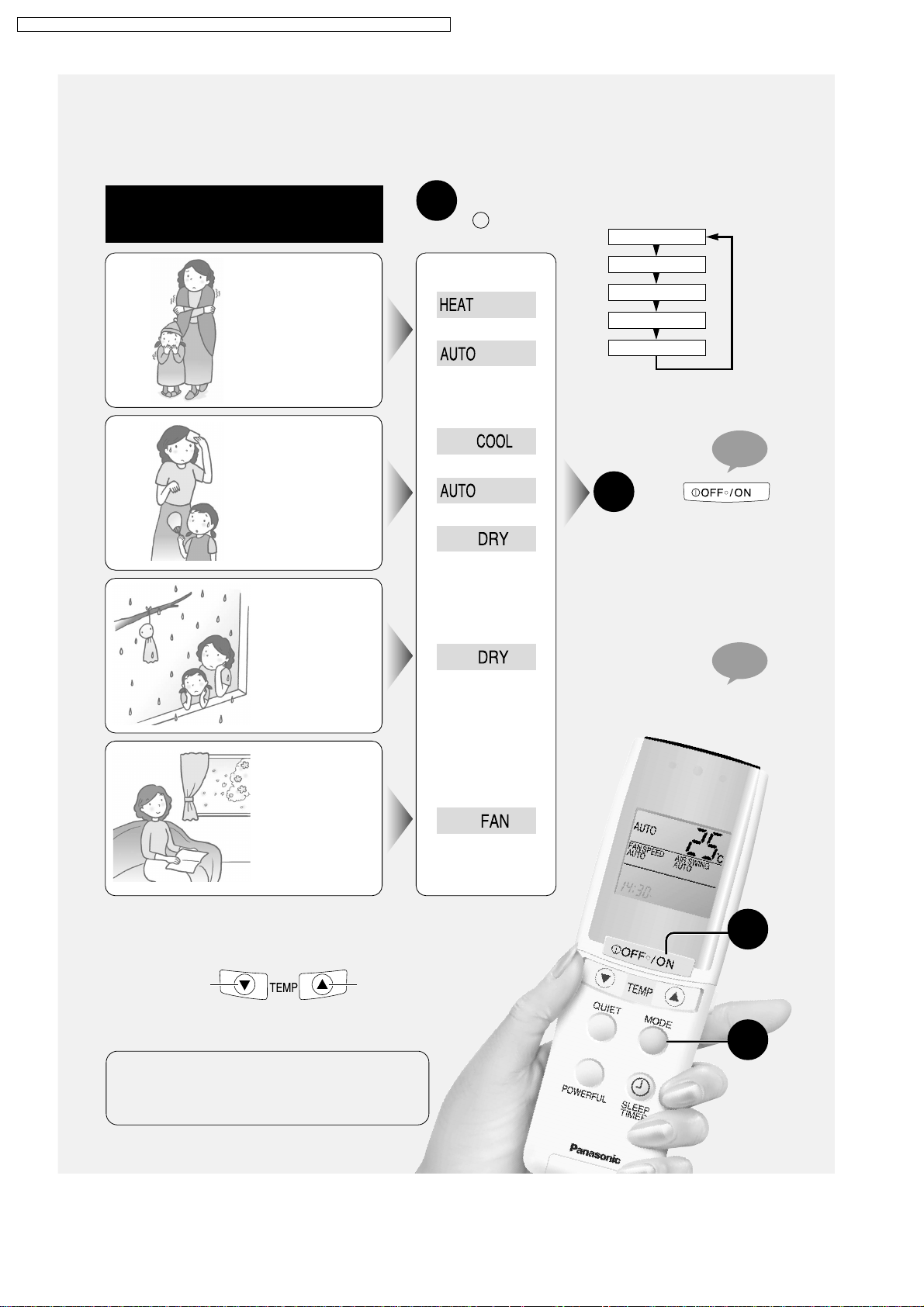
Convenience Operation
Convenience Operation
CS-ME7CB1P / CS-ME 10CB1P / CS-ME12CB1 P / CS-ME14CB1P / CS-ME10CD3P / CS- ME14CD3P
Convenience Operation
Convenience Operation
Automatic operation •
Heating • Cooling • Dry •
Air circulation operation
WHEN
IT IS
COLD
WHEN
IT IS
HOT
WHEN
After connecting the
power supply, press
1
MODE
button to select
operating mode
Display in the
remote control
Or
Or
Or
● Continuously pressing the
button, operation changes
in this order:
AUTO
HEAT
COOL
DRY
FAN
“BEEP”
Press
2
button
● The operation light on the indoor
unit will light up.
● During Auto operation / Heating
operating mode, the operation
light will light up.
● During Heating / Cooling / Dry
operating mode, you may not
get an instant air flow.
IT IS
HUMID
WHEN
HEATING /
COOLING /
DRY ARE NOT
REQUIRED
Please also refer to “Fan speed / Air swing Adjustment” chapters.
■ SETTING TEMPERATURE
INCREASEDECREASE
● Setting range: 16 ~ 30°C
● Each press on the button will change by 1°C. Continuously
pressing the button will speed up the changes.
RECOMMENDED TEMPERA TURE
Select suitable temperature will save electricity consumption.
Heating : 20 ~ 22°C
Cooling : 26 ~ 28°C
Dry : 22 ~ 26°C
■ TO STOP
OPERATION
Press one more time.
“BEEP”
2
1
42

CS-ME7CB1P / CS-ME 10CB1P / CS-ME12CB1 P / CS-ME14CB1P / CS-ME10CD3P / CS- ME14CD3P
Names of Parts and Preparations
Indoor unit
Vertical air flow
direction louvre
Intake grille
Air outlet vent
Air intake vent
Model number
Horizontal air flow
direction louvre
Indication panel
“POWER” indication lamp (green)
“TIMER” indication lamp (orange)
POWER
TIMER
ODOUR WASH
“ODOUR WASH” indication lamp (green)
Remote control signal receiver
Long or short “beep” when signal received.
Auto Restart Control
●
If there is a power failure, operation will be automatically restarted under the previous operation mode and air
flow direction when power is resumed. (When the operation is not stopped by remote control.)
●
If you do not want the unit to restart automatically when power is resumed, switch off the main power supply.
●
Auto Restart Control is not available when Timer or Sleep mode is set or the dry mode timer is cancelled.
43

CS-ME7CB1P / CS-ME 10CB1P / CS-ME12CB1 P / CS-ME14CB1P / CS-ME10CD3P / CS- ME14CD3P
Cassette Type
■ When the intake grille is open
To open
Press in the 3 places shown.
PushPushPush
AUTO
OFF/ON
DRAIN TEST
AUTO OPERATION BUTTON
When not using the remote control.
Continuously pressing the button for
about 5 seconds, a “Beep” sound will
be heard. Force control for cooling
operations is selected. It is not
( )
recommended under normal
circumstances.
To close
Press in the 3 places shown.
PushPushPush
Air filter ( one each for right side and left side)
DRAIN TEST button
Used only when installing.
(Not used normally.)
Release lever
44

CS-ME7CB1P / CS-ME 10CB1P / CS-ME12CB1 P / CS-ME14CB1P / CS-ME10CD3P / CS- ME14CD3P
Names of Parts and Preparations
Duct Type
Indoor unit
* Air intake vent
* Air outlet vent
Receiver unit
* Not supplied by manufacturer.
■ Receiver unit
Remote control signal receiver
Long or short “beep” when signal
received.
“POWER” indication lamp (green)
“TIMER” indication lamp (orange)
“ODOUR WASH” indication lamp
(green)
Auto Restart Control
●
If there is a power failure, operation will be automatically restarted under the previous operation mode and air
flow direction when power is resumed. (When the operation is not stopped by remote control.)
●
If you do not want the unit to restart automatically when power is resumed, switch off the main power supply.
●
Auto Restart Control is not available when Timer or Sleep mode is set or the dry mode timer is cancelled.
POWER TIMER
AUTO
OFF/ON
ODOUR
WASH
AUTO OPERATION BUTTON
When not using the remote control.
Continuously pressing the button for
about 5 seconds, a “Beep” sound will
be heard. Force control for cooling
operations is selected. It is not
( )
recommended under normal
circumstances.
45

CS-ME7CB1P / CS-ME 10CB1P / CS-ME12CB1 P / CS-ME14CB1P / CS-ME10CD3P / CS- ME14CD3P
F an Speed / Air Swing Adjustment
Changing the fan speed
Press
● You may select from 5 stages of fan speed apart from the
auto fan speed.
● Continuously pressing:
The indication will change accordingly.
The increase in size of indication indicates higher fan speed.
Low High
● During DRY mode, should the room temperature is higher
than the remote control set temperature, the fan speed will
be running to that set by the remote control. Whenever the
room temperature approaches the set temperature level,
the fan speed will be running in the Low fan speed
regardless of the indication.
■ AUTOMATIC FAN SPEED
HEATING:
Fan speed will be running in the Low fan speed when the
air temperature is low. Fan speed will be running in the
High fan speed when the air temperature is high.
COOLING / DRY:
During COOLING mode, adjust the fan speed to create
cool air flow.
The air flow will be delayed for 40 seconds during the start
of operations under the COOLING / DRY modes.
Furthermore, sometimes there may be air flow cut off
during operation. Read the instructions for the wall-mounted
type (CS-ME7CKPG). (Page 22)
Changing the vertical air flow directions
Press
● You may select from 5 stages of air flow direction apart
from the auto air swing.
● Continuously pressing:
The indication will change accordingly
(The indications are just air flow direction guidelines, which
may differ with the actual indoor unit louvre positions and
angles)
NOTE
● You cannot change the air flow direction on the duct type.
46

CS-ME7CB1P / CS-ME 10CB1P / CS-ME12CB1 P / CS-ME14CB1P / CS-ME10CD3P / CS- ME14CD3P
F an Speed / Air Swing Adjustment
Vertical air flow direction
■ Setting automatic air flow directions
HEATING
During starting of operations and other circumstances when the
air temperature is low, the air flow blows horizontally.
When temperature is high, air flow is blown down, then it starts
swinging.
COOLING • DRY • AIR CIRCULATION
Automatically it sets to swing up and swing down.
● Adjust the vertical air flow directions by only using the remote
control. (To prevent mistakes, condensation and damage)
● At the end of operation, the louvres will automatically close up
the air flow outlet vents.
● The louvres will automatically adjust its air flow angles to
prevent condensation (during COOLING / DRY) and cold air
blowing out (during HEATING).
● The louvres adjustment range during HEA TING and COOLING
/ DRY may not be the same.
Louvres adjustment angles
You can adjust the
louvres in 5 steps
within these ranges.
Approximately
50 degrees
NOTE
● You cannot change the air flow direction on the duct type.
Horizontal air flow direction
● Manually grip and move the horizontal air flow louvres.
● The blower fan of the indoor unit is operating at a high speed, hence, be careful not to insert your fingers into
the portion behind the louvres.
NOTE
● You cannot change the air flow direction on the duct type.
47

CS-ME7CB1P / CS-ME 10CB1P / CS-ME12CB1 P / CS-ME14CB1P / CS-ME10CD3P / CS- ME14CD3P
Care and maintenance
Cassette T ype
Caution
■ Ensure that the operation is stopped,
power supply is off before you do the air
conditioner cleaning.
The internal high speed fan may cause injuries.
Cleaning the air filter
Press in the 3 places
shown to open the
1
intake grille.
PushPushPush
2
(about once every one and a half months)
Remove the air filter
■ Ensure that you are on firm footing
before attempting to repair or service
the air conditioner.
The unit in operation may cause injuries.
Suck up the dust and dirt
by a vacuum cleaner
3
Installing the air
filter
4
Insert the tabs into the slots and
push up.
Grasp the tab and pull down.
Press in the 3 places
shown to close the
5
intake grille.
For stubborn dirt and grime, apply mild
kitchen detergent (neutral type) and rinse
with water. Leave it to dry in the sun.
(Avoid drying them near the stove or
electric dryer)
NOTE
● If the filters are being used over an extended
period of time without timely servicing, their
performance may decrease and foul odour may
build up.
● The maintenance period may be used as a
criterion. However, if operating conditions cause
build up of odours, you need to service it as soon
as possible.
PushPushPush
ITEMS SOLD SEPARATELY
PART NAME PART NUMBER
Air filter CWD00228
48

CS-ME7CB1P / CS-ME 10CB1P / CS-ME12CB1 P / CS-ME14CB1P / CS-ME10CD3P / CS- ME14CD3P
Care and maintenance
Cleaning the intake grille
Release lever
Left hinge
String
(stops the grille from falling)
Raise the intake grille (Keep hold of the intake grille when detaching it.)
1
(Must be removed from unit before washing)
Center hinge
Intake grille
Right hinge
Cassette Type
PushPushPush
Press in the 3 places shown to open
the intake grille.
Wash and dry the intake grille
2
Cleanse with a soft cloth and sponge.
Then, wipe dry the excess moisture and leave the panel to dry in the shade.
● Avoid pressing hard on the surface and avoid the use of a hard brush. (To prevent injuries)
● Apply some mild kitchen detergent (neutral type) to wash off stubborn dirt and grime.
● Avoid drying the panel in direct sunlight or over a stove.
(May cause color fading and structural distortions)
To fix the intake grille
3
Right hinge
Fit the grille to the hinge on the right of
the main unit.
Release lever
Hold onto the intake grille and slide the
release lever to release the hinge.
Release lever
3
Slide and hold the release lever in
place, then fit the grille into place and
release the lever.
1
2
Release the string from the intake grille.
Attach the string to the grille, then press
in the 3 places (shown in the first
illustration in step 1 ) to close the intake
grille.
49

POWER
TIMER
ODOUR WASH
CS-ME7CB1P / CS-ME 10CB1P / CS-ME12CB1 P / CS-ME14CB1P / CS-ME10CD3P / CS- ME14CD3P
Tr oubleshooting
The following symptoms are not faults. Please continue to use it without fear.
Is it faulty? No, it is okay
● Sound of flowing water:
There is noise.
For details about items not covered here, read the operating instructions attached at the outdoor uint for model
CS-ME7CKPG.
Is it okay? Consult your dealer
• Caused by the flow of refrigerant gas through the air conditioner system.
• Caused by the flow of condensated water by drain pump.
Self diagnosis
■ The TIMER lamp blinks
Cassette Type Duct Type
POWER
TIMER
ODOUR WASH
■ How to self diagnosis
Press for 5 seconds
1
● 3 alphanumeric digits will appear on the remote control display.
When the indoor unit gives off a continuous
2
“Beep, Beep, Beep, Beep” sound, slowly and
repeatedly press
● Inform your dealer on the displayed 3 alphanumeric digits.
DISPLAYED ALPHANUMERIC DIGITS
The H and F (followed by 2 numerals)
H
F
When H33, H36 and H37 are displayed, you must not
operate until repairs have been done.
represent different sets of abnormalities.
H36 : Heating • Air circulation
H37 : Cooling • Dry • Air circulation
Receiver unit
POWER TIMER
AUTO
OFF/ON
ODOUR
WASH
Notify them of all abnormalities.
You can self diagnose using the remote
control. Follow the instructions below. After
confirmation, stop all operations and switch
off the power supply.
“Beep, Beep,
Beep, Beep”
Press for 5 seconds, u sing the remote control select and
operate the Heating • Cooling • Dry • Air circulation modes . (There will
be “Beep, Beep, Beep, Beep” sound to confirm the command is
received).
50

CS-ME7CB1P / CS-ME 10CB1P / CS-ME12CB1 P / CS-ME14CB1P / CS-ME10CD3P / CS- ME14CD3P
Helpful Information
Helpful Information
■ When the remote control is not available and the batteries are out.
It is still possible for emergency operations. In this case, the unit will operate on the default temperature of 25°C.
Adjustment to the default temperature is not allowed.
Switch on the power supply
1
Press the auto operation button.
2
■ To stop operation, press the button once more.
Cassette Type Duct Type
Auto operation button
AUTO
OFF/ON
ODOUR
WASH
AUTO
OFF/ON
Auto operation
button
POWER TIMER
■ When there is a power failure
● During operation:
All operations stopped. When power supply is restored, run operations all over again.
● During preset timer mode:
The timer mode is cancelled. (The indoor unit TIMER lamp will be off) When power supply is restored, reset TIMER
once again.
■ When there is thunder in the vicinity:
To avoid lightning strikes, stop all operations and switch off the power supply. (To protect the air conditioner)
■ After you have used wax:
Be sure the furniture wax is fully dried before starting the air conditioner.
■ Placing things around the indoor unit:
Allow a lot of spacing if you wish to place things around the indoor unit.
If tall furniture are placed near the unit, it may hinder the air flow which will reduce the efficiency of the unit.
■ When the unit is not operated for an extended period of time:
Operate the AIR CIRCULATION
mode for 2 to 3 hours
(To dry the interior sections of the
indoor unit)
Stop the operations
and switch off the
power supply.
Remove all batteries from the
remote control.
(To prevent electrolyte leakage)
51

CS-ME7CB1P / CS-ME 10CB1P / CS-ME12CB1 P / CS-ME14CB1P / CS-ME10CD3P / CS- ME14CD3P
Safety Precaution
WARNING
1) This appliance must be earthed.
2) If the supply cord is damaged or needed to be replaced, it must be replaced by authorized
service agent or a similarly qualified person in order to avoid a hazard.
3) Remove power plug or disconnect from the main power supply before servicing this
appliance.
4) Do not repair by yourself.
In case of malfunction of this appliance, do not repair by yourself.
Contact to the sales dealer or service dealer for a repair.
5) Do not use in an explosive atmosphere.
Do not use this appliance in a potentially explosive atmosphere.
6) Turn off the power (Isolation from main power supply).
Pull off the power plug from the receptacle, or switch off the breaker, or switch off power
disconnecting mean to isolate the equipment from the main power supply in case of an
emergency.
* Airborne noise.
A-weighted sound pressure level of this appliance is less than 70dB (A) under the JIS
C 9612 test conditions.
Maximum cooling operation 1 m from the unit
■ Notes
• If the unit is not going to be used for an extended period of time, turn off the main Power
supply. If it is left at the ON position, approximately 14 W of electricity will be used even if
the indoor unit has been turned off with the remote control.
• If operation is stopped, then restart immediately , the unit will resume operation only after 3
minutes.
Use under the following conditions
DBT:Dry Bulb Temp
WBT:Wet Bulb Temp
Maximum Temperature
Minimum Temperature
Indoor
DBT WBT
32 23
16 11
Cooling
Outdoor Indoor
DBT WBT
43 26
16 11
DBT WBT WBT
30 –
2 –
(Unit in °C)
Heating
Outdoor
DBT
24 18
-5 -6
52

CS-ME7CB1P / CS-ME 10CB1P / CS-ME12CB1 P / CS-ME14CB1P / CS-ME10CD3P / CS- ME14CD3P
12 Disassembly of Parts
12.1. Cassette Type (Indoor Unit: CSME7CB1P/ME10CB1P/ME12CB1P/ME14CB1P)
12.1.1. Detaching the fan motor and cross flow fan
1) Open the air inlet section of the front grille.
2) Unscrew the 4 screws on the front grille, then disengage the
catches with a screwdriver and detach the front grille.
3) Loosen the screw on the cover and detach the cover.
4) Unscrew the 2 screws on the control section cover.
5) Detach the connectors going from the control board to the drain
pump and from the receiver and display sections.
6) Unscrew the screw and disengage the 2 catches on the air
outlet grille, then take out the drain pan plug to drain off excess
water.
7) Unscrew the 4 screws and disengage the 5 catches on the
drain pan.
53

CS-ME7CB1P / CS-ME 10CB1P / CS-ME12CB1 P / CS-ME14CB1P / CS-ME10CD3P / CS- ME14CD3P
12.1.2. Detaching the drain pump
8) Detach the air guide and unscrew the screw on the heat
exchanger.
9) Detach the float switch and unscrew the 3 screws and
disengage the 2 catches on the fan motor holder.
10) Loosen the screw fixing the shaft between the cross flow fan
and the fan motor and detach the fan motor.
11) Remove the cross flow fan.
8) Unscrew the screw on the drain pump holder and detach it.
9) Detach the drain hose from the drain pump and remove the
drain pump.
54

12.1.3. Detaching the control board
CS-ME7CB1P / CS-ME 10CB1P / CS-ME12CB1 P / CS-ME14CB1P / CS-ME10CD3P / CS- ME14CD3P
1) Open the air inlet section of the front grille.
2) Unscrew the 4 screws on the front grille, then disengage the
catches with a screwdriver and detach the front grille.
3) Loosen the screw on the cover and detach the cover.
4) Unscrew the 2 screws on the control section cover and detach
all connectors.
5) Disengage the catch on the control board and remove it.
55

CS-ME7CB1P / CS-ME 10CB1P / CS-ME12CB1 P / CS-ME14CB1P / CS-ME10CD3P / CS- ME14CD3P
12.1.4. Detaching the louver motor
3) Loosen the screw on the cover and detach the cover.
4) Unscrew the 2 screws on the control section cover and detach
the connector for the louver motor.
5) Unscrew the screw and disengage the 2 catches on the air
outlet grille.
6) Unscrew the 2 screws on the louver motor on the back of the air
outlet grille and remove the louver motor.
56

CS-ME7CB1P / CS-ME 10CB1P / CS-ME12CB1 P / CS-ME14CB1P / CS-ME10CD3P / CS- ME14CD3P
12.2. Duct Type (Indoor Unit: CS-ME10CD3P/ME14CD3P)
12.2.1. Detaching the upper and inner casing
1) Unscrew the 4 screws on the upper and inner casing and
detach them.
12.2.2. Detaching the control board
1) First detach the upper and inner casing (12.2.1.).
2) Unscrew the 2 screws on the slide guide.
3) Pull the board down following the slide guide.
4) Lift the control board up from the bottom, disengage the catch
holding the board and open it.
57

CS-ME7CB1P / CS-ME 10CB1P / CS-ME12CB1 P / CS-ME14CB1P / CS-ME10CD3P / CS- ME14CD3P
12.2.3. Detaching the fan
1) First detach the upper and inner casing (12.2.1.).
2) Disengage the 4 catches (2 each on the left and right) on the
air guide.
3) Use a 2.5 mm hexagonal wrench to loosen the bolt
connecting the fan motor and fan, detach the shaft connecting
the fan motor and fan, loosen the screw holding the fan and
detach the fan.
12.2.4. Detaching the fan motor and drain motor
1) First detach the upper and inner casing (12.2.1.) and the fan
2) Unscrew the 4 screws holding the fan motor and detach it.
1) First detach the upper and inner casing (12.2.1.) and the fan
2) From the fan motor side, undo the 2 hexagon bolts and detach
Fan motor
(12.2.3.).
Drain motor
(12.2.3.).
the drain motor.
58

13 Technical Data
13.1. OPERATION CHARACTERISTICS
CS-ME7CB1P / CS-ME 10CB1P / CS-ME12CB1 P / CS-ME14CB1P / CS-ME10CD3P / CS- ME14CD3P
59

CS-ME7CB1P / CS-ME 10CB1P / CS-ME12CB1 P / CS-ME14CB1P / CS-ME10CD3P / CS- ME14CD3P61CS-ME7CB1P / CS-ME 10CB1P / CS-ME12CB1 P / CS-ME14CB1P / CS-ME10CD3P / CS- ME14CD3P
60


CS-ME7CB1P / CS-ME 10CB1P / CS-ME12CB1 P / CS-ME14CB1P / CS-ME10CD3P / CS- ME14CD3P
62

14 Electronic Circuit Diagram
14.1. REMOTE CONTROL
H
SEG14
P33
SW2
SEG15
SEG16
P00
P01
J30J2
SEG15
SEG16
SEG17
SEG18
SEG19
SEG20
SEG21
SEG22
SEG23
SEG24
SEG25
SEG26
SEG27
SEG28
SEG29
SEG30
SEG31
SEG32
SEG17
SEG18
SEG19
SEG20
SEG21
P02
P03
P10
P11
P12
13 14 15 16
9 10 11 12
G
F
SEG10
COM0
COM1
COM2
COM3
SEG9
SEG8
SEG7
SEG6
SEG5
SEG4
SEG3
SEG2
SEG1
COM3
COM2
COM1
COM0
Liquid
Crystal
Display
E
SEG7
SEG8
SEG9
SEG11
SEG10
SEG12
SS
V
RES
P30
SEG13
IC1
SBL3036M
P31
P32
0
SEG6
1
SEG5
2
SEG4
3
SEG3
4
SEG2
D
R4
100K
R5
C
B
100K
R6
100K
X1
(3.52MHz)
EF0EC3524M4W
X2
(32.768kHz)
C002RX
R3
330K
5
SEG1
6
COM3
7
COM2
8
COM1
9
10
COM0
11
VLCD3
12
VLCD2
13
VLCD1
14
DD
V
15
OSC1
OSC2
16
XO
XI
17 18 19 20 21 22 23 24 25 26 27 28 29 30 31 32
J-A J-B
CS-ME7CB1P / CS-ME 10CB1P / CS-ME12CB1 P / CS-ME14CB1P / CS-ME10CD3P / CS- ME14CD3P
Remote Control
Transmission Code Change
Setting
ON: Connected
OFF: Disconnected
J-A J-B
AON
B
OFF
C
ON
D
OFF
ON
ON
OFF
OFF
Remarks
At product delivery
Remote Control Key
49505152535455565758596061626364
SEG23
SEG24
SEG25
SEG26
SEG27
SEG28
SEG29
SEG30
SEG31
SEG32
SEG22
RMO
P40
P23
P22
P21
P20
P13
Key No.
SW2 OFF
(Door is opened) (Door is closed)
1 OFF / ON
FAN SPEED
2
AIR SWING
3
ODOUR WASH
4
5
ON (Timer)
6
OFF (Timer)
7
48
47
46
45
44
43
42
41
40
39
38
37
36
35
34
33
8
9
10
11
12
13
14
15
16
(Timer)
(Timer)
CANCEL (Timer)
SET (Timer)
CLOCK
SET
R7
47
C2
4V
100
R1
2.2
D1
SID303
C1
4V
100
SW2 ON
OFF / ON
TEMP
TEMP
QUIET
MODE
POWERFUL
SLEEP TIMER
SET
BATTERY
R2
5 6 7 8
C5
0.1
RESET
terminal
1
2 3 4
1K
Q1
2SD1328STX
A
123456
63

14.2. Cassette Type
CS-ME7C B1P / CS-ME10CB1 P / CS-ME 12CB1P / CS-ME14CB1 P / CS-ME 10CD3P / CS-ME14 CD3P
64
ELECTRONIC CIRCUIT DIAGRAM
H
VH5-3
FUSE 3.15A
CN-AC
231
Terminal
Board Ass'y
DM
UPC2800AGR
IN+8
7
INCD
6
GND
5 4
1
3
5
VH3-2
CN-DRMTR
1
3
V
CC1
OUT
V
CC2
fo
C46
250VAC
2200P
SSR-DR
K6G1ABC00001
RECEIVER
CW
1
2
2
1
3
3
Thermal Fuse
G
To Outdoor Unit
DRAIN MOTOR
F
IC101 A52R2-AGR
RECEIVER
PH302C
(SHIELD CASE)
5V
LED201
E
D
C
120
115
110
105
100
95
90
85
)
B
80
75
70
65
60
55
50
RESISTANCE (k
45
40
35
30
25
20
15
10
5
0
A
-100 102030405060
1 Indoor intake air temp
2 Indoor pipe temp
Power
Odour Wash
Timer
Timer Table
Function
24 hours OFF/ON timer
Cooling FC max
Hot start forced completion
Hot start forced completion after deice
Auto mode judgment sampling time
Sleep mode timer shift
Thermo off timer
Deice completion timer(Indication) 5 min. 0
Powerful mode operation time count
Anti-dew formation control
Anti-freezing control
Drain pump forced ON timer 05 min.
Drain pump delayed OFF after operation OFF
Sensor Characteristics
2
1
TEMP ( )
A54LNK3151B3
Indoor
STEPPING MOTOR
1 hour 1 min.
30 min. 3 sec.
180 min.
30 sec.
60 min.
120 min.
180 min.
300 min.
420 min.
30 min.
20 min.
D1
RA15-06V3
R1
13K 1/2W
R3
13K 1/2W
A742574
5V
AUTO
SW2
EVQQKH08Q
PH6
CN-RCV1
6
5
4
3
2
1
Time Test mode
7 min. 0
3 min. 18 sec.
18 sec.
0
6 sec.
12 sec.
18 sec.
30 sec.
42 sec.
18 sec.3 min.
0
0
0
6 min.
30 sec. 3 sec.
Drain Test
SW1
EVQQKH08Q
Float SW
CS-ME7CB1P,CS-ME10CB1P,CS-ME12CB1P,CS-ME14CB1P
R85
22K
1/2W
R86
22K
1/2W
R87
22K
1/2W
R88
22K
1/2W
Q3
DTA143XK
2
RST
8
CS
3
BUSY
1
7
R32
150K
R33
100K
C22
50V
2.2
(NHG)
R481KR50
IC5
A52A2003GR2
SSR-DR
BZ
C12
450V
68
C5
50V
33
(FZ)
R20
R22
R21
R24 5.1KR23 10K
C10
3300P
(MB)
C27
0.01
1K
10
11
12
13
1413
16
T1 ETXAC073X3B
C
B
D
A
G
E
F
5V
R17
10K
R29
C24
10K
50V
10
(NHG)
12V
9
7
6
5
4
215
8
R18
5.1K
C7
0.022
360
430
360
L4,5
5V
A43BL18AG121
L4 L5
C25
0.01
L6
A43BL18AG121
ZNR1
ERZVEAV511
R2
13K 1/2W
R4
13K 1/2W
5
4
3
2
1
R5
100K
1/4W
R6
100K
1/4W
CN-RCV1
9
8
7
6
5
4
3
2
1
XH-3
CN-FSW
3
2
1
XH-5
CN-STM
5
4
3
2
1
ZD1
A54D36EB1TB
ZD2
A54D36EB1TB
PH-6
TH1
ERF7TJ100 10 7W
C1
250VAC
0.22
R7
R8
510K
510K
1/4W
1/4W
D2
RA15-06V3
R10
1.21K
1%
5V
R44
1K
R9
3.9K
D3
A541SS355T
PC2
TLP421 (GR)
5V
R45
1K
LF1
G0B353D00002
3 2
1 4
PC3
TLP421 (BL)
C11
16V
0.1
(KB)
R43
10K
R46
10K
12V
JP2
DB1
PC1
PS2501 (KC)
32
5V
R80
5.6K
R13
47K
C20
0.01
C4
250VAC
0.1
R15
100
R14
10K
Q1
2SC2412K
5V
C21
0.01
B0EBNR000008
C8
1000P
(MB)
R28
10K
IC3
C0EBH0000160
R81
22K
1/2W
R82
22K
1/2W
R83
22K
1/2W
R84
22K
1/2W
5V
R16
10K
C6
0.1
(KB)
IC2
C3EBFG000019
R27
10K
6
5
X1
A454M00G56A0
(47PX2) 4MHz
OGI
D9
RA15-06V3
Q2
DTC143XK
SCK4
D0
DI
5V
C2
250VAC
1000P
C3
250VAC
1000P
1 4
14
R11
680
R12
20.0K
1%
32
5V
R47
R42
1K
C28
0.01
C29
1000P
1K
12V
5V
BZ
R55 1K
IC1
IC7
12V
T001
1
8
3
6
9
1
R76
10K
C38
50V
10
(NHG)
R60
10K
5
6
C34
1000P
(MB)
D6 D7 D8
7
2
4
5
C41
0.01
R72
5.90K
1%
5V
R61
22.1K
1%
R63
220
C33
R62
50V
11.0K
1
1%
(NHG)
D6-8
A541SS355T
4
5 6
12
14
11
13
3
18 21097
R26
1K
R25
10K
R30
10K
R31
10K
C26
0.01
76
80
P1277P1378P1479P15
T021
T062
RXD
3
4
TXD
SI
5
6
S0
SCK
7
8
RESET
V
DD9
10
X2
X1
11
VSS
12
IC(VPP)
13
P90
14
P91
15
16
P92
P93
17
P94
18
P95
19
P40
20
P41
P4222P4323P4424P4525P4626P4727P5028P5129P5230P5331P5432VSS33P5534P5635P5736P6037P6138P6239P63
21
74
75
P11
P10
70
71
72
73
VSS
P05
P07
INTP5
IC1
A52D4956G123
67
68
69
P02
P04
INTP2
R34
1K
R35
10K
65
P0066P01
JP3 JP4
63
64
AVSS
AVREF
(TEST) (5V)
61
ANI5
ANI662ANI7
ANI4
ANI3
ANI2
ANI1
ANI0
AVDD
VDD
VSS
P37
P36
P35
P34
P33
P32
T01
P30
P67
P66
P65
P64
40
58
6
R37
374
1%
60
59
58
57
56
55
54
53
52
51
50
49
48
47
46
45
44
43
42
41
7
4
5V
R36
143
1%
C31
10V
1
(ZF)
5V
3
2
R73
1K
R74
1K
R71
15.0K
1%
5V
C23
10V
1
(ZF)
R59
10K
D4
A541SS355T
7
R56 5.1K
R57 5.1K
R58 5.1K
C13
25V
820
(FC)
C17
630V
1000P
C18
50V
390
(FC)
R77
1K
C39
50V
10
(NHG)
5V
R64
25.5K
1%
C35
1000P
(MB)
1
IC4
C0BBBZ00006
5V
8
4
C14
0.01
L1
EXCML32A680U
R65
18.2K
1%
PH4
5V
CN-TH1
2
3
5V
C37
50V
1
(NHG)
S13050NA
OGI
L2
EXCML32A680U
ELECTRONIC
CONTROLLER
1
2
3
4
C32
C36
50V
1000P
10
(MB)
(NHG)
D5
A541SS355T
L3
A43BL18AG121
C15
10V
100
(NHG)
AIR TEMP SENSOR
PIPE TEMP SENSOR
5V
R66
49.9K
1%
R67
5.49K
1%
R69
5.11K
1%
R70
5.11K
1%
5V
C19
50V
390
(FC)
R78
19.6K
1%
R68
0.33
2WS
2%
(15K ,3950)
(20K ,3950)
C16
10V
100
(NHG)
5V
Sensor
Circuit
LogicLogic Logic
1921
13141112910 22
Drive
Circuit
RA
RA
RA
Drive
Circuit
835
5V
JP1
R38 1K
R39
10K
IC6
C1FB00000004
18
16
C44
15
1000P
R79
C45
(MB)
1M
1000P
(MB)
17
C42
C43
1000P
1000P
(MB)
(MB)
27
XH3
CN-MTR
23
1
4
6
20
Microprocessor: A52D4956G123
Pin No. Port No. Description
1
TO2
Buzzer Drive
2
TO6
Data Reception
3
RXD
Data Transmission
4
TXD
5
SI
6
SO
7
SCK
Reset Signal
8
RESET
+5V
9
Vdd
4MHz Oscillation
10
X2
4MHz Oscillation
11
X1
GND
12
Vss
GND
13
IC(VPP)
Data
14
P90
15
P91
16
P92
17
P93
18
P94
19
P95
20
P40
21
P41
22
P42
23
P43
24
P44
25
P45
26
P46
27
P47
Fan Motor Drive
28
P50
Fan Motor Drive
29
P51
Fan Motor Drive
30
P52
Fan Motor Drive
31
P53
Fan Motor Drive
32
P54
GND
33
Vss
Fan Motor Drive
34
P55
Fan Speed Detection
35
P56
36
P57
Stepping Motor Drive
37
P60
Stepping Motor Drive
38
P61
Stepping Motor Drive
39
P62
Stepping Motor Drive
40
P63
41
P64
SSR-DR Drive
42
P65
Drain Test
43
P66
44
Float Switch
P67
45
P30
46
Fan Speed Control
TD1
47
P32
48
P33
49
P34
50
P35
51
P36
52
P37
53
GND
Vss
54
Vdd
55
+5V
AVDD
56
Fan Speed Control
ANI0
57
ANI1
58
ANI2
59
ANI3
60
ANI4
Pipe Temperature
61
ANI5
Intake Air Temperature
62
ANI6
63
ANI7
64
AVSS
65
AVREF
Power
66
P00
67
P01
Test
68
P02
Clock Pulse
69
INTP2
Fan Speed Control
70
P04
Auto Switch
71
P05
72
INTP5
Remote Control Signal
73
P07
74
Vss
GND
75
P10
76
P11
77
P12
78
P13
Display Odour Wash
79
P14
Display Power
Display Timer
80
P15
(W)
1
5
(V)
2
3
FM
(U)
3
1
FAN MOTOR
123456789101112

14.3. Duct Type
65
ELECTRONIC CIRCUIT DIAGRAM
H
VH7-4
CN-AC
7
Thermal Fuse
G
Terminal
2 31
Board Ass'y
To Outdoor Unit
IC201 UPC2800AGR
RECEIVER
PH302C
(SHIELD CASE)
DM
UPC2800AGR
IN+8
7
INCD
6
5 4
GND
DRAIN MOTOR
F
E
Odour Wash
DISPLAY
CWA742576
D
Timer Table
Function
24 hours OFF/ON timer
Cooling FC max
Hot start forced completion
Hot start forced completion after deice
Auto mode judgment sampling time
Sleep mode timer shift
C
Thermo off timer
Deice completion timer(Indication) 5min. 0
Powerful mode operation time count
Anti-dew formation control
Anti-freezing control
Drain pump forced ON timer 05 min.
Drain pump delayed OFF after operation OFF
5
3
1
VH3-2
CN-DRMTR
3
1
CC1
V
OUT
CC2
V
fo
AUTO
Power
Timer
1
2
3
Indoor
C33
250VAC
2200P
(ME)
SSR-DR
K6G1ABC00001
SW201
LED204
LED202
LED203
FUSE
3.15A
2
1
3
Time Test mode
1 hour 1 min.
30 min. 3 sec.
7 min. 0
3 min. 18 sec.
180 min.
30 sec.
60 min.
120 min.
180 min.
300 min.
420 min.
30 min.
20 min.
6 min.
30 sec. 3 sec.
B
A
C41
250VAC
4700P
(ME)
C39
250VAC
2200P
(ME)
D1
RA15-06V3
C42
250VAC
2200P
(ME)
C40
250VAC
4700P
(ME)
CS-ME10CD3P,CS-ME14CD3P
LF1
R70
ERF10TK6R8 6.8
TH1
ERF10TK6R8 6.8
R7
510K
1/4W
D2
RA15-06V3
ZD1
A54D36EB1TB
ZD2
A54D36EB1TB
XH8
5V
G0B273E00005
C1
250VAC
1
(ECQU)
R9
3.9K
R8
510K
D3
1/4W
A541SS355T
PC2
TLP421 (GR)
14
3 2
1 4
R10
1.21K
1%
32
PC3
TLP421 (BL)
5V
C34
0.1
(KB)
R32
C22
10K
3300P
(MB)
5V
R65
R54
1K
10K
R66
1K
R55
10K
12V
R1
6.8K
2WS
XH8
CN-RCV
18 sec.
0
6 sec.
12 sec.
18 sec.
30 sec.
42 sec.
18 sec.3 min.
0
0
0
DRAIN TEST
SW1
K0H1BA000305
FLOAT SW
ZNR1
ERZVEAV511
1
2
3
4
5
6
7
8
R5
100K
1/4W
R6
100K
1/4W
R2
6.2K
2WS
CN-DISP
1
2
3
4
5
6
7
8
XH3
CN-FSW
1
2
3
PH6
CN-STM
1
2
3
4
5
6
ETXMJ251X1C
DB1
PC1
PS2501 (KC)
32
5V
R69
5.6K
R13
47K
C2
250VAC
0.22
(ECQU)
R15
100
R14
10K
Q1
2SC2412K
C23
1000P
(MB)
C18
10V
1
5V
C19
0.01
5V
R34 1K
B0EBNR000008
R46
10K
IC4
C0EBH0000160
BZ
BZ
C13
0.1
(KB)
IC3
C3EBFG000019
R45
10K
6
5
X1
A454M00G56A0
(47PX2) 4MHZ
OGI
12V
5V
R16
10K
SCK4
D0
DI
5V
C27
50V
2.2
IC5
A52A2003GR2
Q2
DTC143XK
2
RST
CS
BUSY
7
R48
100K
SSR-DR
C4
250VAC
4700P
(MF)
C3
250VAC
4700P
(MF)
1 4
R11
680
R12
20.0K
R33
5.1K
R22
1K
C15
0.01
C35
1000P
(MB)
R49
150K
C5
450V
68
(EET)
Q3
DTA143XK
8
3
1
C20
0.01
R24
R26
R25
R47
10K
10
11
12
13
1413
16
15V
C6
25V
120
(FC)
5V
R17
10K
360
430
360
C26
50V
10
12V
9
7
6
5
4
215
8
T1
C
D4
SC201-4T
B
R19
6.8K
1/4W
A
R002R003
D
E
8
7 6
FA13842N
R001
D001
C002
R18
5.1K
C14
0.022
C17
0.01
5V
C21
0.01
3
4
5
6
7
8
10
11
12
13
14
15
16
17
18
19
20
1 254
C012
C001 R021
C003
R31
1K
R29
10K
R30
1K
R50
10K
73
74
75
76
80
P11
VSS
P10
P1277P1378P1479P15
T021
T062
RXD
TXD
SI
S0
SCK
RESET
DD9
V
X2
X1
VSS
IC(VPP)
P90
P91
P92
P93
P94
P95
P40
IC1
A52D4956G123
P41
P4222P4323P4424P4525P4626P4727P5028P5129P5230P5331P5432VSS33P5534P5635P5736P6037P6138P6239P63
21
5V
R012
D002
Q002
R011
R009
R020
R005
R015
Q003
3
R006
R018 C011
R008
R010
D003
C004
Q001
R004
R007
R019
67
68
69
70
71
72
P02
P05
P04
P07
INTP2
INTP5
C006
C007
R017 R016 ZD001
C005
R59
1K
R58
10K
R23
10K
61
63
64
65
ANI5
P0066P01
ANI662ANI7
AVSS
ANI4
60
AVREF
ANI3
59
ANI2
58
ANI1
57
ANI0
56
AVDD
55
VDD
54
VSS
53
P37
52
P36
51
P35
50
P34
49
P33
48
P32
47
T01
46
P30
45
P67
44
P66
43
P65
42
P64
41
40
R52
10K
R53
10K
P2
C009
R014
D004
R013
C010
B2
(TEST) (5V)
JP2 JP1
5V
C28
10V
1
5V
C29
10V
1
5V
R57
10K
S3
T001
2
C7
D101
P1
S4
4
S1
D102
S2
5
B1
R20
25V
100K
470
(FC)
L2
J0JHC0000040
C9
R21
25V
560K
470
(FC)
5V
R67
1K
C36
R51
0.01
10K
R60
143
1%
R61
374
1%
R62
15.0K
1%
R68
5.6K
C37
R27
0.01
10K
C31
R63
C30
50V
5.90K
50V
10
10
1%
5V
1 4
R38
Q6
1K
DTC143XK
5V
PC5
TLP521
(GB)
3 2
R43
5V
1 4
1K
R44
20K
Q5
DTA143XK
32
PC6
TLP521
(GB)
R42
1K
C25
1000P
(MB)
L1
J0JHC0000040
SW2
K0D112A00064
High State
ON: High
OFF: Normal
R37
4.3K
32
14
R41
4.75K
1%
PC4
TLP521
(GB)
R40
5.11K
1%
L3
J0JHC0000040
R36
10K
R35
7.5K
12V
C8
0.01
IC2
SI3050NAF
OGI
C10
0.01
120
115
110
105
100
95
90
85
)
80
75
70
65
60
55
50
RESISTANCE (k
45
40
35
30
25
20
5V
15
10
5
0
-100 102030405060
1 Indoor intake air temp
2 Indoor pipe temp
5V
XH4
5V
CN-TH
15V
Q4
2SB1188
R39
10K
C24
ZD3
50V
RD6.8M-T1B
10
ELECTRONIC
CONTROLLER
5V
C12
C11
100
0.01
Sensor Characteristics
2
1
TEMP ( )
1
AIR TEMP SENSOR
2
3
4
PIPE TEMP SENSOR
(15K ,3950)
(20K ,3950)
IC1
Pin No. Port No. Description
1
2
3
4
5
6
7
8
9
10
11
12
13
14
15
16
17
18
19
20
21
22
23
24
25
26
27
28
29
30
31
32
33
34
35
36
37
38
39
40
41
42
43
44
45
46
47
48
49
50
51
52
53
54
55
56
57
58
59
60
61
62
63
64
65
66
67
68
69
70
71
72
73
74
75
76
77
78
79
80
XH7-5
CN-FM
1
4
5
6
7
Microprocessor: A52D4956G123
TO2
TO6
Buzzer Drive
RXD
Data Reception
TXD
Data Transmission
SI
SO
SCK
Reset Signal
RESET
Vdd
+5V
X2
4MHz Oscillation
X1
4MHz Oscillation
Vss
GND
IC(VPP)
GND
P90
Data
P91
P92
P93
P94
P95
P40
P41
P42
P43
P44
P45
P46
P47
P50
P51
P52
P53
P54
Vss
GND
P55
P56
P57
P60
P61
P62
P63
P64
P65
SSR-DR Drive
P66
Drain Test
P67
Float Switch
P30
TD1
Fan Speed Control
P32
Fan Motor ON/OFF 15V
P33
P34
P35
P36
P37
Vss
GND
Vdd
AVDD
+5V
ANI0
ANI1
ANI2
ANI3
ANI4
Pipe Temperature
ANI5
Intake Air Temperature
ANI6
ANI7
Installation Position Switch
AVSS
AVREF
Power
P00
P01
Test
P02
Clock Pulse
INTP2
Fan Speed Detection
P04
Auto Switch
P05
High Static Pressure Switch
INTP5
Remote Control Signal
P07
Vss
GND
P10
P11
P12
P13
Display Odour Wash
P14
Display Power
Display Timer
P15
FM
FAN MOTOR
CS-ME7C B1P / CS-ME10CB1 P / CS-ME 12CB1P / CS-ME14CB1 P / CS-ME 10CD3P / CS-ME14 CD3P
123456789101112

CS-ME7CB1P / CS-ME 10CB1P / CS-ME12CB1 P / CS-ME14CB1P / CS-ME10CD3P / CS- ME14CD3P
15 Exploded View & Replacement Parts List
15.1. CS-ME7CB1P/ME10CB1P/ME12CB1P/ME14CB1P
15.1.1. Exploded View
Note:
The above exploded view is for the purpose of parts disassembly and replacement.
The non-numbered parts are not kept as standard service parts.
66

CS-ME7CB1P / CS-ME10CB1P / CS-ME12CB1P / CS-ME14CB1P / CS-ME10CD3P / CS-ME14CD3P
15.1.2. Replacement Parts List
<Model: CS-ME7CB1P / CS-ME10CB1P / CS-ME12CB1P / CS-ME14CB1P>
Ref.
No.
1 FLOAT SWITCH 1 CWA12326 ←←←← ←←←← ←←←←
2 THERMAL FUSE 1 CWA16C1031 ←←←← ←←←← ←←←←
3 TERMINAL BOARD COMPLETE 1 CWA28K1045 ←←←← ←←←← ←←←←
4 SENSOR COMPLETE 1 CWA50C2100
5 TERMINAL PLATE FOR EARTH 1 CWA64C1005 ←←←← ←←←← ←←←←
6 LEAD WIRE COMPLETE (FM) 1 CWA67C1641 ←←←← ←←←← ←←←←
7 LEAD WIRE COMPLETE (AS) 1 CWA67C1643 ←←←← ←←←← ←←←←
8 PC BOARD (MAIN) 1 CWA73C1458 CWA73C1459 CWA73C1460 CWA73C1461
9 PC BOARD (RECEIVER) 1 CWA742574 ←←←← ←←←← ←←←←
10 REMOTE CONTROL 1 CWA75C2311 ←←←← ←←←← ←←←←
11 AIR SWING MOTOR 1 CWA98168
12 FAN MOTOR 1 CWA98258 ←←←← ←←←← ←←←←
13 EVAPORATOR 1 CWB302119
14 DRAIN PUMP 1 CWB532010 ←←←← ←←←← ←←←←
16 DRAIN CAP 1 CWB82018
17 CHASSIS COMPLETE 1 CWD50C260 ←←←← ←←←← ←←←←
18 FAN MOTOR BRACKET 1 CWD54232 ←←←← ←←←← ←←←←
19 PARTICULAR PLATE 1 CWD66238 ←←←← ←←←← ←←←←
20 PARTICULAR PIECE-1 1 CWD76223
21 PARTICULAR PIECE-2 1 CWD76225 ←←←← ←←←← ←←←←
22 PARTICULAR PIECE-3 4 CWD91197 ←←←← ←←←← ←←←←
23 DRAIN PUMP BRACKET 1 CWD93938 ←←←← ←←←← ←←←←
24 DISCHARGE GRILE COMPLETE 1 CWE20C2232 ←←←← ←←←← ←←←←
25 LOUVER 1 CWE24423 ←←←← ←←←← ←←←←
26 VERTICAL LOUVER 1 CWE24C101 ←←←← ←←←← ←←←←
27 DECORATION PANEL 1 CWE35243 ←←←← ←←←← ←←←←
28 INDICATION PLATE 1 CWE39280 ←←←← ←←←← ←←←←
31 INSULATION SHEET 2 CWG10467 ←←←← ←←←← ←←←←
34 CROSS-FLOW FAN COMPLETE 1 CWH02K117X ←←←← ←←←← ←←←←
35 CONTROL BOARD BOX 1 CWH10931 ←←←← ←←←← ←←←←
36 CONTROL COVER-1 1 CWH131172 ←←←← ←←←← ←←←←
37 CONTROL COVER-2 1 CWH13424 ←←←← ←←←← ←←←←
38 CONTROL COVER-3 1 CWH13426 ←←←← ←←←← ←←←←
40 HOLDER SENSOR 1 CWH32137 ←←←← ←←←← ←←←←
43 DRAIN TRAY 1 CWH40C1022 ←←←← ←←←← ←←←←
44 BELT 3 CWH4605004 ←←←← ←←←← ←←←←
45 GUTTER 1 CWH481002X ←←←← ←←←← ←←←←
46 BUSHING FOR DRAIN PUMP-1 1 CWH50196 ←←←← ←←←← ←←←←
47 BUSHING FOR DRAIN PUMP-2 1 CWH50197 ←←←← ←←←← ←←←←
48 BUSHING 1 CWH50198 ←←←← ←←←← CWH501030
49 CAP (1/4) 1 CWH52061 ←←←← ←←←← ←←←←
50 CAP (3/8) 1 CWH52062 ←←←← ←←←← ←←←←
51 CAP 1 CWH52160 ←←←← ←←←← ←←←←
52 FLUCRUM 1 CWH64C017 ←←←← ←←←← ←←←←
54 DRAIN PIPE 1 CWH85266 ←←←← ←←←← ←←←←
55 DRAIN HOSE COMPLETE 1 CWH85C038 ←←←← ←←←← ←←←←
56 TUBE ASSY (3/8) 1 CWT022528 ←←←← ←←←← CWT022529
57 TUBE ASSY (1/4) 1 CWT022530 ←←←← ←←←← CWT022531
58 FLARE NUT (1/4) 1 CWT25086 ←←←← ←←←← ←←←←
59 FLARE NUT (3/8) 1 CWT25087 ←←←← ←←←← ←←←←
62 JOINT FOR DRAIN PIPE 1 CWT29116 ←←←← ←←←← ←←←←
63 ZNR 1 ERZVEAV511 ←←←← ←←←← ←←←←
64 FUSE (250V 3A) 1 K5D312BB0002 ←←←← ←←←← ←←←←
65 OPERATING INSTRUCTIONS 1 CWF563997 ←←←← ←←←← ←←←←
66 INSTALLATION INSTRUCTIONS 1 CWF612424 ←←←← ←←←← ←←←←
Part Name & Description Q´ty Part No. Remarks
CS-ME7CB1P CS-ME10CB1P CS-ME12CB1P CS-ME14CB1P
←←←← ←←←← ←←←←
←←←← ←←←← ←←←←
←←←← ←←←←
←←←← ←←←← ←←←←
←←←← ←←←← ←←←←
CWB30C1171
llll
llll
llll
llll
llll
llll
llll
llll
llll
llll
(Note)
· "l" marked parts are recommended to be kept in stock.
· All parts are supplied from ACD, JAPAN (VENDER CODE : 00025800).
67

CS-ME7CB1P / CS-ME 10CB1P / CS-ME12CB1 P / CS-ME14CB1P / CS-ME10CD3P / CS- ME14CD3P
15.2. CS-ME10CD3P/ME14CD3P
15.2.1. Exploded View
Note:
The above exploded view is for the purpose of parts disassembly and replacement.
The non-numbered parts are not kept as standard service parts.
68

CS-ME7CB1P / CS-ME10CB1P / CS-ME12CB1P / CS-ME14CB1P / CS-ME10CD3P / CS-ME14CD3P
15.2.2. Replacement Parts List
<Model: CS-ME10CD3P / CS-ME14CD3P>
Ref. No. Part Name & Description Q´ty Part No. Remarks
1 FLOAT SWITCH 1 CWA12161 ←←←←
2 THERMAL FUSE 1 CWA16C1030 ←←←←
3 TERMINAL BOARD COMPLETE 1 CWA28K188 ←←←←
6 SENSOR COMPLETE 1 CWA50C2116
9 REMOTE CONTROL (RECEIVER) 1 CWA75C2337 ←←←←
10 REMOTE CONTROL 1 CWA75C2311 ←←←←
11 FAN MOTOR 1 CWA981071 ←←←←
12 EVAPORATOR 1 CWB302123 ←←←←
13 DRAIN PUMP 1 CWB53C1010 ←←←←
14 PARTICULAR PLATE-1 1 CWD11024X ←←←←
15 AIR GUIDER-1 2 CWD32091
16 AIR GUIDER-2 2 CWD32092 ←←←←
17 BOTTOM PLATE 1 CWD52259
18 BULKHEAD 1 CWD53063 ←←←←
19 BRACKET FAN MOTOR 1 CWD541036
20 PARTICULAR PLATE-2 1 CWD74100 ←←←←
22 HOLDER LEAD WIRE-1 1 CWD77003 ←←←←
23 PARTICULAR PLATE-3 1 CWD90K080 ←←←←
24 PARTICULAR PLATE-4 1 CWD90616
25 PARTICULAR PLATE-5 1 CWD90618 ←←←←
26 PARTICULAR PLATE-6 1 CWD90766 ←←←←
27 CABINET BACK PLATE 1 CWE02079 ←←←←
28 CABINET TOP PLATE-1 1 CWE03034 ←←←←
29 CABINET TOP PLATE-2 2 CWE03035 ←←←←
30 CABINET SIDE PLATE-1 1 CWE04071 ←←←←
31 CABINET SIDE PLATE-2 1 CWE04072 ←←←←
42 INSULATION SHEET-1 1 CWG07165 ←←←←
43 INSULATION SHEET-2 1 CWG07166 ←←←←
44 INSULATION SHEET-3 1 CWG07167 ←←←←
45 CROSS-FLOW FAN COMPLETE 1 CWH01C005 ←←←←
47 CONTROL BOARD BOX 1 CWH10527 ←←←←
48 CONTROL COVER 1 CWH131144 ←←←←
49 HOLDER LEAD WIRE-2 2 CWH31062 ←←←←
50 HOLDER LEAD WIRE-3 2 CWH31030 ←←←←
51 HOLDER LEAD WIRE-4 2 CWH31044 ←←←←
53 DRAIN TRAY 1 CWH40C061 ←←←←
54 BELT 1 CWH4605008 ←←←←
55 BUSHING-1 2 CWH4610440 ←←←←
56 CAP-1 1 CWH52061 ←←←←
59 BUSHING-2 1 CWH50147 ←←←←
60 BUSHING-3 1 CWH50146 ←←←←
61 BUSHING-4 1 CWH51134 ←←←←
62 CAP-2 1 CWH52062 ←←←←
64 FULCRUM 1 CWH64C015 ←←←←
65 GUIDER-1 1 CWH69024 ←←←←
66 GUIDER-2 1 CWH69025 ←←←←
67 FLARE NUT (1/4) 1 CWT25086 ←←←←
68 DRAIN HOSE 1 CWH85C008 ←←←←
70 TUBE ASSY 1 CWT01C2422 ←←←←
71 FLARE NUT (3/8) 1 CWT25087 ←←←←
81 COVER FOR RECEIVER 1 CWD66132B ←←←←
82 RECEIVER PIECE-1 1 CWD90650 ←←←←
83 PARTICULAR PIECE-1 2 CWD93435 ←←←←
85 PARTICULAR PIECE-2 2 CWD93436 ←←←←
86 CABINET BOTTMO PLATE 1 CWE05012 ←←←←
87 HOLDER SENSOR-2 1 CWH32137 ←←←←
88 PC BOARD (MAIN) 1 CWA73C1462 CWA73C1463
90 FUSE (250V 3A) 1 K5D312BB0002 ←←←←
91 ZNR 1 ERZVEAV511 ←←←←
92 OPERATING INSTRUCTIONS 1 CWF563997 ←←←←
93 INSTALLATION INSTRUCTIONS 1 CWF612425 ←←←←
CS-ME10CD3P CS-ME14CD3P
←←←←
←←←←
←←←←
←←←←
←←←←
llll
llll
llll
llll
llll
llll
llll
llll
llll
(Note)
· "l" marked parts are recommended to be kept in stock.
· All parts are supplied from ACD, JAPAN (VENDER CODE : 00025800).
69
Printed in Japan
 Loading...