

Panasonic cs-ks12nb41 installation

INSTALLATION INSTRUCTIONSAPPENDIX B
CS-KS12NB41 & CZ-18BT1U + CU-KS12NK1A
CS-KS18NB4UW & CZ-18BT1U + CU-KS18NKU
CS-KS18NB4UW & CZ-18BT1U + CU-KS18NKUA
(852-6-4190-574-00-1)
A-2

INSTALLATION INSTRUCTIONS
Split System Air Conditioner
This air conditioner uses the refrigerant R410A.
NOTE
External diameter of service port R410A: 5/16"
Model Combinations
Combine indoor and outdoor units only as listed
below.
Model No.
Indoor Unit Outdoor Unit
CS-KS12NB41 CU-KS12NK1A
Power Source:
60 Hz, single-phase, 115 V
CS-KS18NB4UW CU-KS18NKU
CU-KS18NKUA
Power Source:
60 Hz, single-phase, 230/208 V
Ceiling Panel
CZ-18BT1U
Contents
Page
IMPORTANT!
Please Read Before Starting .................................. 2
1. GENERAL .......................................................... 4
1-1. Tools Required for Installation (not supplied)
1-2. Accessories Supplied with Unit
1-3. Optional Copper Tubing Kit
1-4. Type of Copper Tube and Insulation Material
1-5. Additional Materials Required for Installation
2. INSTALLATION SITE SELECTION ................... 5
2-1. Indoor Unit
2-2. Outdoor Unit
2-3. Baffle Plate for the Outdoor Unit
3. HOW TO INSTALL THE INDOOR UNIT ........... 12
3-1. Preparation for Suspending
3-2. Suspending the Indoor Unit
3-3. Placing the Unit Inside the Ceiling
3-4. Installing the Drain Piping
3-5. Checking the Drainage
3-6. How to Install the Ceiling Panel
3-7. Wiring Instructions
3-8. Recommended Wire Length and Diameter
3-9. Wiring Instructions for Inter-unit Connections
4. HOW TO INSTALL THE OUTDOOR UNIT ....... 20
4-1. Wiring Instructions for the Outdoor Unit
5. REFRIGERANT TUBING .................................. 21
5-1. Use of the Flaring Method
5-2. Flaring Procedure with a Flare Tool
5-3. Caution before Connecting Tubes Tightly
5-4. Connecting Tubing between Indoor and
Outdoor Units
5-5. Insulation of Refrigerant Tubing
5-6. Taping the Tubes
5-7. Finishing the Installation
6. AIR PURGING................................................... 23
Air Purging with a Vacuum Pump (for Test Run)
Basic Functions of the Service Valves
Pump Down
Service Valve Connections
7. REMOTE CONTROLLER INSTALLATION
POSITION ......................................................... 27
7-1. Mounting on a Wall
8. ADDRESS SWITCH .......................................... 28
8-1. Address Setting of the Remote Controller
85264190574001 2011
CV6233187785
IMPORTANT!
Please Read Before Starting
This air conditioning system meets strict safety and operating
standards. As the installer or service person, it is an important
part of your job to install or service the system so it operates
safely and efficiently.
When Transporting
Be careful when picking up and moving the indoor and outdoor units. Get a partner to help, and bend your knees when
lifting to reduce strain on your back. Sharp edges or thin aluminum fins on the air conditioner can cut your fingers.
When Installing…
For safe installation and trouble-free operation, you
must:
Carefully read this instruction booklet before beginning.
Follow each installation or repair step exactly as shown.
Observe all local, state, and national electrical codes.
Pay close attention to all warning and caution notices
given in this manual.
This symbol refers to a hazard
WARNING
CAUTION
or unsafe practice which can
result in severe personal injury
or death.
This symbol refers to a hazard
or unsafe practice which can
result in personal injury or product or property damage.
If Necessary, Get Help
These instructions are all you need for most installation
sites and maintenance conditions. If you require help for a
special problem, contact our sales/service outlet or your
certified dealer for additional instructions.
In Case of Improper Installation
The manufacturer shall in no way be responsible for improper installation or maintenance service, including failure to
follow the instructions in this document.
SPECIAL PRECAUTIONS
Select an installation location which is rigid and strong
enough to support or hold the unit, and select a location for
easy maintenance.
…In a Ceiling or Wall
Make sure the ceiling/wall is strong enough to hold the
unit’s weight. It may be necessary to construct a strong
wood or metal frame to provide added support.
…In a Room
Properly insulate any tubing run inside a room to prevent
“sweating” that can cause dripping and water damage to
walls and floors.
Keep the fire alarm and the air
CAUTION
…In Moist or Uneven Locations
Use a raised concrete pad or concrete blocks to provide a
solid, level foundation for the outdoor unit. This prevents
water damage and abnormal vibration.
…In an Area with High Winds
Securely anchor the outdoor unit down with bolts and a
metal frame. Provide a suitable air baffle.
…In a Snowy Area (for Heat Pump-type Systems)
Install the outdoor unit on a raised platform that is higher
than drifting snow. Provide snow vents.
outlet at least 1.5 m away from
the unit.
WARNING
'RQRWVXSSO\SRZHUWRWKHXQLWXQWLODOOZLULQJDQGWXELQJ
are completed or reconnected and checked.
+LJKO\GDQJHURXVHOHFWULFDOYROWDJHVDUHXVHGLQWKLV
system. Carefully refer to the wiring diagram and these
instructions when wiring. Improper connections and
inadequate grounding can cause accidental injury or
death.
*URXQGWKHXQLW following local electrical codes.
&RQQHFWDOOZLULQJWLJKWO\/RRVHZLULQJPD\FDXVHRYHU
heating at connection points and a possible fire hazard.
7RSUHYHQWSRVVLEOHKD]DUGVIURPLQVXODWLRQIDLOXUH
the unit must be grounded.
When Wiring
ELECTRICAL SHOCK CAN CAUSE SEVERE
PERSONAL INJURY OR DEATH. ONLY A
QUALIFIED, EXPERIENCED ELECTRICIAN
SHOULD ATTEMPT TO WIRE THIS SYSTEM.
When Connecting Refrigerant Tubing
:KHQSHUIRUPLQJpiping work
do not mix air except for specified refrigerant (R410A) in
refrigeration cycle. It causes
capacity down, and risk of
explosion and injury due to
high tension inside the refrige-
WARNING
9HQWLODWHWKHURRPZHOOLQWKHHYHQWWKDWUHIULJHUDQW
gas leaks during the installation. Be careful not to allow
contact of the refrigerant gas with a flame as this will
cause the generation of poisonous gas.
2
rant cycle.
5HIULJHUDQWJDVOHDNDJHPD\
cause fire.
'RQRWDGGRUUHSODFHUHIULJHUDQW
other than specified type.
It may cause product damage,
burst and injury etc.

8VHWKHIODUHPHWKRGIRUFRQQHFWLQJWXELQJ
$SSO\UHIULJHUDQWOXEULFDQWWRWKHPDWFKLQJVXUIDFHVRI
the flare and union tubes before connecting them,
then tighten the nut with a torque wrench for a leakfree connection.
&KHFNFDUHIXOO\IRUOHDNVEHIRUHVWDUWLQJWKHWHVWUXQ
'RQRWOHDNUHIULJHUDQWZKLOHSLSLQJZRUNIRUDQLQVWDOODWLRQ
or re-installation, and while repairing refrigeration parts.
Handle liquid refrigerant carefully as it may cause frostbite.
When Servicing
7XUQWKHSRZHU2)) DWWKHPDLQSRZHUER[PDLQV
before opening the unit to check or repair electrical
parts and wiring.
.HHS\RXUILQJHUVDQGFORWKLQJDZD\IURPDQ\PRYLQJ
parts.
&OHDQXSWKHVLWHDIWHU\RXILQLVKUHPHPEHULQJWRFKHFN
that no metal scraps or bits of wiring have been left inside
the unit being serviced.
Others
CAUTION
9HQWLODWHDQ\HQFORVHGDUHDVZKHQLQVWDOOLQJRUWHVWLQJ
the refrigeration system. Escaped refrigerant gas, on
contact with fire or heat, can produce dangerously
toxic gas.
&RQILUPXSRQFRPSOHWLQJLQVWDOODWLRQWKDWQRUHIULJHUDQW
gas is leaking. If escaped gas comes in contact with a
stove, gas water heater, electric room heater or other heat
source, it can produce dangerously toxic gas.
'RQRWWRXFKWKHDLULQOHWRUWKHVKDUSDOXPLQXP
fins of the outdoor unit. You may get injured.
'RQRWVLWRUVWHSRQWKHXQLW\RXPD\IDOOGRZQ
accidentally.
'RQRWVWLFNDQ\REMHFWLQWRWKH)$1&$6(
You may be injured and the unit may be damaged.
NOTE
The illustrations are based on the typical appearance of
a standard model. Consequently, the shape may differ
from that of the air conditioner that you are installing.
3

1. General
This booklet briefly outlines where and how to install the air conditioning system. Please read over the entire set of instructions for the indoor and outdoor units and make sure all accessory parts listed are with the system before beginning.
1-1. Tools Required for Installation (not supplied)
1. Standard screwdriver
2. Phillips head screwdriver
3. Knife or wire stripper
4. Tape measure
5. Carpenter’s level
1-2. Accessories Supplied with Unit
Table 1
Parts PartsFigure RemarksQ’ty Figure
Washer
Flare
insulation
Insulation tape
Vinyl tie
Drain hose
insulation
Remote
controller
Remote control
holder
AAA alkaline
battery
Full-scale
installation
diagram
1/8"(T3)
3/16"(T5)
3/32"(T2)
13/32"(T10)
set
6. Sabre saw or key hole saw
7. Hacksaw
8. Core bits
9. Hammer
10. Drill
For temporarily
suspending indoor
8
unit from ceiling
For wide /
2
narrow tube
connection
For wide /
narrow tube /
2
flare nut connection
For flare / drain
insulating
8
connection
For drain tube
1
connection
1
1
2
Printed on
1
container box
Truss head screw
Drain hose
Hose band
Tapping screw
Cushion rubber
Truss head screw
Special screw
11. Tube cutter
12. Tube flaring tool
13. Torque wrench
14. Adjustable wrench
15. Reamer (for deburring)
3/16 13/32"
(5 10mm)
5-1/2"(L140)
Truss-head Phillips
5/32 5/8"
(4 16mm)
5/32 15/32"
(4 12mm)
3/16 1-9/16"
(5 40mm)
Use M10 or 3/8" for suspension bolts.
Suspension bolts and nuts (locally purchased)
For full-scale
installation
4
diagram
For unit & PVC
1
tube connection
For drain hose
2
connection
2
Packed in the
4
outdoor unit
4
Packed in the
ceiling panel
4
RemarksQ’ty
1-3. Optional Copper Tubing Kit
Copper tubing for connecting the outdoor unit to the indoor unit is available in kits which contain the narrow and wide
tubing, fittings and insulation. Consult your nearest sales outlet or air conditioning workshop.
1-4. Type of Copper Tube and Insulation Material
If you wish to purchase these materials separately from a local source, you will need:
1. Deoxidized annealed copper tube for refrigerant tubing as detailed in Table 2.
Cut each tube to the appropriate lengths 1' to 1'4" (30 cm to 40 cm) to dampen vibration between units.
2. Foamed polyethylene insulation for the specified copper tubes as required to precise length of tubing. Wall thickness
of the insulation should be not less than 5/16" (8 mm).
3. Use insulated copper wire for field wiring. Wire size varies with the total length of wiring. Refer to 3-7. Wiring
Instructions for details.
CAUTION
Table 2
Model
CS-KS12NB41 1/4" (6.35 mm) 0.0314" (0.8 mm) 3/8" (9.52 mm) 0.0314" (0.8 mm)
CS-KS18NB4UW 1/4" (6.35 mm) 0.0314" (0.8 mm) 1/2" (12.70 mm) 0.0314" (0.8 mm)
Outer Dia. Thickness Outer Dia. Thickness
Narrow Tube Wide Tube
4
Check local electrical codes
and regulations before
obtaining wire. Also, check
any specified instructions or
limitations.

1-5. Additional Materials Required for Installation
1. Refrigeration (armored) tape
2. Insulated staples or clamps for connecting wire
(See local codes)
3. Putty
4. Refrigeration lubricant
5. Clamps or saddles to secure refrigerant tubing
2. Installation Site Selection
2-1. Indoor Unit
WARNING
To prevent abnormal heat generation and the possibility of fire, do
not place obstacles, enclosures
and grilles in front of or surrounding the air conditioner in a way
that may block air flow.
AVOID:
direct sunlight.
nearby heat sources that may affect performance of the unit.
areas where leakage of flammable gas may be expected.
places where large amounts of oil mist exist.
DO:
select an appropriate position from which every corner of
the room can be uniformly cooled.
select a location that will hold the weight of the unit.
select a location where tubing and drain hose have the
shortest run to the outside.
3.3 ft.
(1m)
3.3 ft.
(1m)
Fig. 1
3.3 ft.
(1m)
3.3 ft.
(1m)
3.3 ft.
(1m)
Indoor unit
allow room for operation and maintenance as well as unre-
stricted air flow around the unit. (Fig. 1)
install the unit within the maximum elevation difference (H)
above or below the outdoor unit and within a total tubing length
Outdoor unit
Tubing length (L)
Elevation difference (H)
Fig. 2
(L) from the outdoor unit as detailed in Table 3 and Fig. 2.
install the indoor unit more than 3.3' (1 m) away from any
antenna or power lines or connecting wires used for television,
radio, telephone, security system, or intercom. Electrical noise
from any of these sources may affect operation.
CAUTION
Air delivery will be degraded if the distance
from the floor to the ceiling is greater than
10 ft. (3 m).
Table 3
Max. Allowable Tubing Limit of Tubing Limit of Elevation Required Amount of
Model Length at Shipment Length (L) Difference (H) Additional Refrigerant
(ft.) (ft.) (ft.) (oz./ft.)*
CS-KS12NB41 25 65 23 0.16
CS-KS18NB4UW 25 100 50 0.27
* If total tubing length becomes 25 to 65 ft. (Max.) or 25 to 100 ft. (Max.), charge additional refrigerant (R410A) by 0.16 or 0.27 oz./ft.
No additional charge of compressor oil is necessary. For more detailed charging information, refer to the Technical & Service Manual.
5
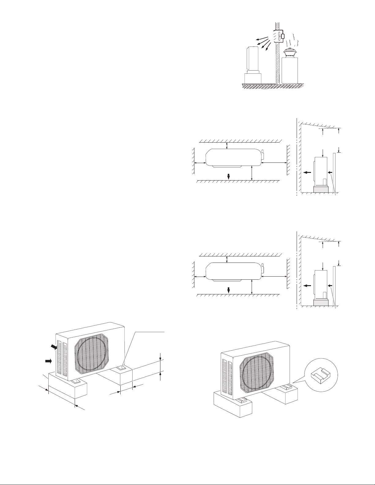
2-2. Outdoor Unit
AVOID:
heat sources, exhaust fans, etc. (Fig. 3)
damp, humid or uneven locations.
DO:
choose a place as cool as possible.
choose a place that is well ventilated.
install in a location where at least two sides are unob-
structed, so that the flow of air at the intake port or
exhaust port is not blocked, and so that sufficient
space is ensured for maintenance to be carried out
without trouble. In general the top also must be unobstructed. (Figs. 4a and 4b)
provide a solid base (level concrete pad, concrete
block, 4" 1'4" (10 40 cm) beams or equal), a minimum of 4" (10 cm) above ground level to reduce
humidity and protect the unit against possible water
damage and decreased service life. (Fig. 5a)
install cushion rubber under unit’s feet to reduce
vibration and noise. (Fig. 5b)
use lug bolts or equal to bolt down unit, reducing
vibration and noise.
install in a location where no antenna of a television
or radio exists within 10' (3 m).
NO
Hot air
Outdoor unit
Fig. 3
(CU-KS12NK1A)
Air intake Min. 2" (5 cm)
Min.
2" (5 cm)
Air discharge
(CU-KS18NKU, CU-KS18NKUA)
Air intake Min. 4" (10 cm)
Min.
2" (5 cm)
Air discharge
Valve
side
Min. 10"
(25 cm)
Min.
8" (20 cm)
Fig. 4a
Valve
side
Min. 10"
(25 cm)
Min.
1'4" (40 cm)
Exhaust fan
Heat source
Obstacle above
Ground
Obstacle above
Min.
7' (2 m)
Air discharge
Min. 2" (5 cm)
Air intake
Min.
7' (2 m)
Air discharge
Min.
7' (2 m)
Obstacle
Min.
7' (2 m)
Obstacle
Air intake
Concrete
or equal
About 1'4" (40 cm)
Anchor bolts
(4 pcs.)
Min. 4" (10 cm)
About 4" (10 cm)
Fig. 4b
Fig. 5a Fig. 5b
6
Ground
Cushion rubber
Min. 4" (10 cm)
Air intake

2-3. Baffle Plate for the Outdoor Unit
(Low Ambient Cooling models only)
Air intake baffle
NOTE
It is recommended to use baffle plates for models
CU-KS12NK1A and CU-KS18NKUA. The baffle plates
are not normally required for the other models.
When the outdoor unit is installed in a position exposed
to strong wind (such as seasonal winds with low air temperature in winter), baffle plates must be installed on the
outdoor unit. (Fig. 5c)
This unit is designed so that the fan of the outdoor unit
runs at low speed when the air conditioner is operated at
low outdoor air temperatures. When the outdoor unit is
exposed to strong wind, the system pressure drops
because of the freeze protector.
Install a pair of windbaffle plates at the front and back of
the outdoor unit if it will be subject to strong wind during
the winter. (Figs. 5c to 5k)
Wind
Back
No air intake baffle
required on
this side.
Front
Wind
Air discharge baffle
Fig. 5c
7

CU-KS12NK1A
(1) Recommended dimensions of the baffle plates
Air Intake Baffle
C
E
D
B
F
A
2- 1/4"
(2- 6.5 mm)
Fig. 5d
2- 15/64"
(2- 6 mm)
Q
P
Air Discharge Baffle
N
H
I
B
H
J
G
4- 1/4"
(4- 6.5 mm)
L
K
G
I
E
A
G
F
D
Fig. 5e
J
C
M
K
For Air Intake
Dimensions
Model
CU-KS12NK1A
(inch)
(mm) 550 20 55 440 330 10 15 9 7.5 441 10 150 20 20
ABCDEFGH I J KNPQ
21-21/32
25/32 2-5/32 17-5/16 13 25/64 19/32 23/64 19/64 17-3/8 25/64 5-29/32 25/32 25/32
For Air Discharge
Dimensions
Model
CU-KS12NK1A
(inch)
(mm) 485 510 350 150 445 20 55 370 70 85 15 35 35
ABCDEFGH I J KLM
19-3/32 20-3/32
13-25/32
5-29/32
17-17/32
25/32 2-5/32 14-9/16 2-3/4 3-11/32 19/32 1-3/8 1-3/8
Material to be used: Metal plate with corrosion protection treatment
Plate thickness: 0.0394 to 0.0472" (1.0 to 1.2 mm)
(2) Parts required (locally purchased except for screws)
Air Intake Baffle
Item Q’ty Remarks
Baffle plate 1
Screw 5/32 15/32" (4 12 mm) tapping 2 Attached to outdoor unit
Bolt 15/64 19/32 – 25/32" (M6 15 – 20 mm) 2
Nut 15/64" (M6) 2
Washer 2
Spring washer 2
Air Discharge Baffle
Item Q’ty Remarks
Baffle plate 1
Bolt 15/64 13/32 – 19/32" (M6 10 – 15 mm) 4
Nut 15/64" (M6) 4
Washer 4
Spring washer 4
8

CU-KS18NKUA
(1) Recommended dimensions of the baffle plates
Air Intake Baffle
C
E
D
F
B
G
Air Discharge Baffle
H
O
A
2- 15/64"
(2- 6 mm)
J
3- 1/4"
(3- 6.5 mm)
R
Q
Fig. 5f Fig. 5g
L
I
K
E
A
F
D
B
(4- 6.5 mm)
G
G
H
4- 1/4"
I
J
C
K
For Air Intake
Dimensions
Model
CU-KS18NKUA
(inch)
(mm) 620 20 45 565 235 235 10 20 15 587 7.5 10 150 20 20
ABCDEFGH I J KLOQR
24-13/32
25/32 1-25/32 22-1/4 9-1/4 9-1/4 25/64 25/32 19/32 23-1/8 19/64 25/64 5-29/32 25/32 25/32
For Air Discharge
Dimensions
Model
CU-KS18NKUA
(inch)
(mm) 530 560 350 150 460 35 55 440 60 85 25
ABCDEFGH I J K
20-7/8 22-1/16
13-25/32
5-29/32 18-1/8 1-3/8 2-5/32 17-5/16 2-3/8 3-11/32 31/32
Material to be used: Metal plate with corrosion protection treatment
Plate thickness: 0.0394 to 0.0472" (1.0 to 1.2 mm)
(2) Parts required (locally purchased except for screws)
Air Intake Baffle
Item Q’ty Remarks
Baffle plate 1
Screw 5/32 15/32" (4 12 mm) tapping 2 Attached to outdoor unit
Bolt 15/64 19/32 – 25/32" (M6 15 – 20 mm) 3
Nut 15/64" (M6) 3
Washer 3
Spring washer 3
Air Discharge Baffle
Item Q’ty Remarks
Baffle plate 1
Bolt 15/64 13/32 – 19/32" (M6 10 – 15 mm) 4
Nut 15/64" (M6) 4
Washer 4
Spring washer 4
9

(3) Installation procedure
CU-KS12NK1A
1. Air Intake Baffle
(1) Left side
1. Remove the front panel from the unit.
2. Remove the panel side L, and drill 2 holes of ø1/4 inch
(6.5 mm) at the prescribed position.
3. Install the windbaffle on the unit using field supply bolts
and nuts.
4. Recommended bolts to be used are 15/64" (M6 ISO
standard), and the recommended length of the bolts is
between 19/32 – 25/32 inch (15 – 20 mm).
5. Use washers and spring washers to tightly fasten the
windbaffle to the unit.
(2) Right side
1. Remove the front panel from the unit.
2. Use 2 preholes on the panel side R to install the baffle
plate.
3. Remove the panel side R from the unit by removing the
screws. These screws are used in step 4 below.
4. Put (sandwich) the windbaffle between the unit and the
panel side R, then install the windbaffle on the unit using
the above screws. Be careful not to damage the screw
holes.
2. Air Discharge Baffle
1. Remove the panels front, side L and R from the unit
and drill 4 holes of ø1/4 inch (6.5 mm) at the
prescribed positions.
2. Install the windbaffle on the unit using field supply
bolts and nuts.
3. Recommended bolts to be used are 15/64" (M6 ISO
standard), and the recommended length of the bolts
is between 13/32 – 19/32 inch (10 – 15 mm).
4. Use washers and spring washers to tightly fasten the
windbaffle to the unit.
Panel side R
Fig. 5h
Panel front
Panel side L
Panel side L
Fig. 5i
Panel side R
Panel front
NOTE
In order to prevent contact of the bolts and heat exchanger and other parts inside the unit, install the windbaffle using
bolts from inside the unit and fasten the bolts with nuts from outside the unit.
When the windbaffle is installed on the unit, the unit has higher wind resistance. In order to prevent the unit from
falling over, anchor the legs of the unit using anchor bolts (or similar method).
10

CU-KS18NKUA
1. Air Intake Baffle
(1) Left side
1. Remove the top panel from the unit.
2. Remove the panel side L, and drill 3 holes of ø1/4 inch
(6.5 mm) at the prescribed positions.
3. Install the windbaffle on the unit using field supply bolts
and nuts.
4. Recommended bolts to be used are 15/64" (M6 ISO
standard), and the recommended length of the bolts is
between 19/32 – 25/32 inch (15 – 20 mm).
5. Use washers and spring washers to tightly fasten the
windbaffle to the unit.
(2) Right side
1. Remove the top panel from the unit.
2. Use 2 preholes on the panel side R to install the baffle plate.
3. Remove the panel side R from the unit by removing the
screws. These screws are used in step 4 below.
4. Put (sandwich) the windbaffle between the unit and the
panel side R, then install the windbaffle on the unit using the
above screws. Be careful not to damage the screw holes.
Panel top
Panel front
2. Air Discharge Baffle
1. Remove the panels front, top, side L and R from the
unit and drill 4 holes of ø1/4 inch (6.5 mm) at the
prescribed positions.
2. Install the windbaffle on the unit using field supply
bolts and nuts.
3. Recommended bolts to be used are 15/64" (M6 ISO
standard), and the recommended length of the bolts
is between 13/32 – 19/32 inch (10 – 15 mm).
4. Use washers and spring washers to tightly fasten the
windbaffle to the unit.
Panel side R
Panel top
Panel side R
Panel front
Panel side L
Panel side L
Fig. 5j
Fig. 5k
NOTE
In order to prevent contact of the bolts and heat exchanger and other parts inside the unit, install the windbaffle using
bolts from inside the unit and fasten the bolts with nuts from outside the unit.
When the windbaffle is installed on the unit, the unit has higher wind resistance. In order to prevent the unit from
falling over, anchor the legs of the unit using anchor bolts (or similar method).
(4) Precautions for installation
1. Be sure not to damage painted surfaces.
2. Finish the edges of the windbaffle to avoid cuts or injury.
3. Drilling of holes must be carefully done so that no damage is caused to external or internal parts of the unit.
Particular care must be taken that drill chips do not drop into the unit.
11
3. How to Install the Indoor Unit
3-1. Preparation for Suspending
This unit uses a drain pump. Use a carpenter’s level to
check that the unit is level.
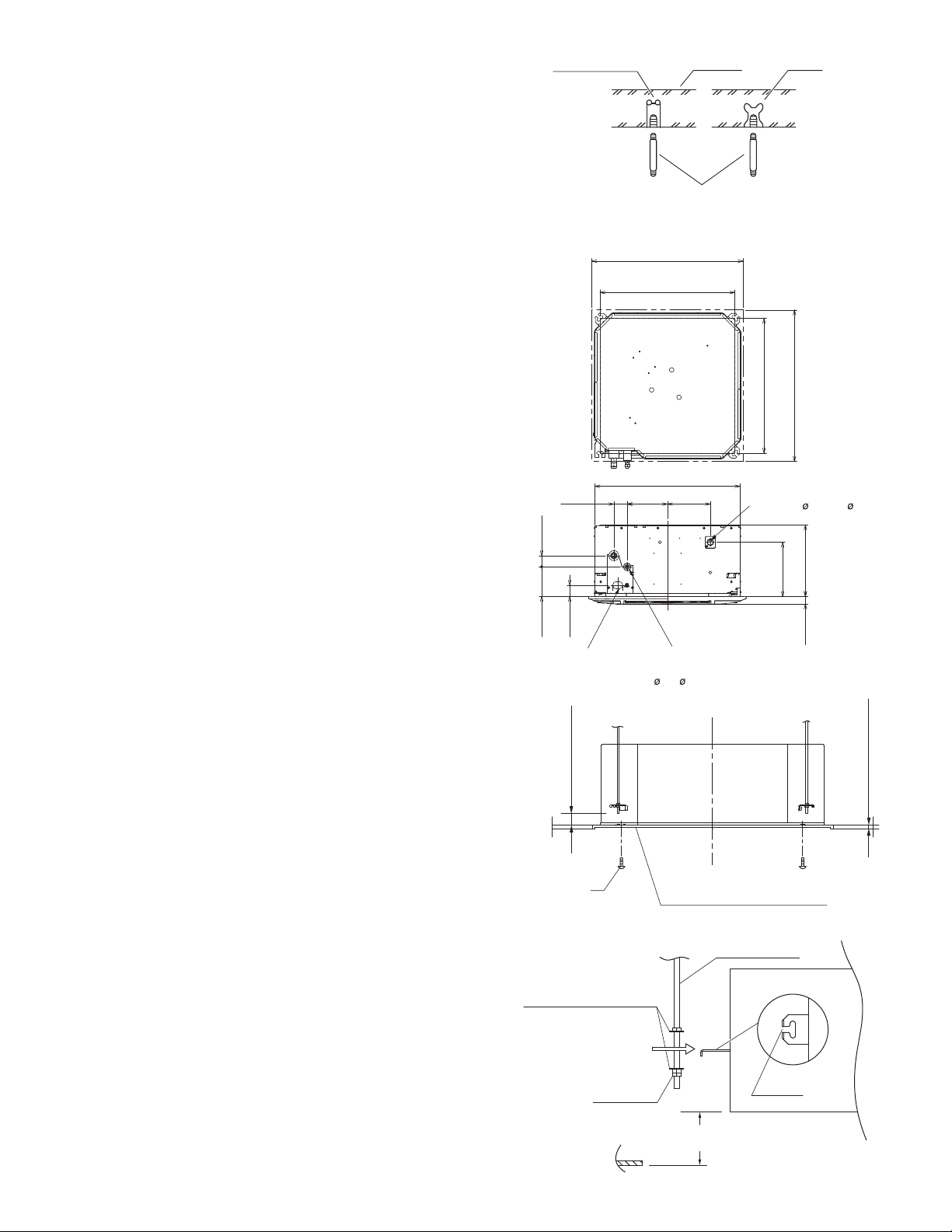
3-2. Suspending the Indoor Unit
(1) Fix the suspension bolts securely in the ceiling using
the method shown in the diagrams, by attaching
them to the ceiling support structure, or by any other
method that ensures that the unit will be securely
and safely suspended. (Fig. 6-1)
(2) Follow the diagram to make the holes in the ceiling.
Hole-in-anchor
Hole-in-plug
Ceiling opening dimensions
21-1/32"(534
Suspension bolt pitch
Concrete Insert
Suspension bolt (M10 or 3/8")
(locally purchased)
Fig. 6-1
23-5/8"(600mm)
mm
)
(3) Determine the pitch of the suspension bolts using
the supplied full-scale installation diagram. The diagram shows the relationship between the positions
of the suspension fitting, unit, and panel. (Fig. 6-2)
3-3. Placing the Unit Inside the Ceiling
(1) Be sure to remove the fan protection (4pcs) for
transportation before hanging up the indoor unit.
(2) When placing the unit inside the ceiling, determine
the pitch of the suspension bolts using the supplied
full-scale installation diagram. (Fig. 6-3)
Tubing and wiring must be laid inside the ceiling
when suspending the unit. If the ceiling is already
constructed, lay the tubing and wiring into position
for connection to the unit before placing the unit
inside the ceiling.
(3) The length of suspension bolts must be appropriate
for a distance between the bottom of the bolt and the
bottom of the unit of more than 19/32" (15 mm) as
shown in the diagram. (Fig. 6-3)
(4) Thread the 3 hexagonal nuts (locally purchased) and
2 supplied washers onto each of the 4 suspension
bolts as shown in the diagram. Use 1 nut and 1
washer for the upper side, and 2 nuts and 1 washer
for the lower side, so that the unit will not fall off the
suspension lugs. (Fig. 6-4)
(5) Adjust so that the distance between the unit and the
ceiling bottom is 1/2" (13 mm) to 23/32" (18 mm).
Tighten the nuts on the upper side and lower side of
the suspension lug. (Fig. 6-4)
)
mm
(45
1-25/32"
)
)
mm
mm
4-19/32"
(45
1-25/32"
(117
Power supply port
)
mm
Over 19/32" (15
Supplied screw
Nuts and washers
(used for upper and lower)
22-5/8"(575mm)
6-5/16"2-3/32"
6-11/16"
mm
)(160mm)(53mm)
(170
Refrigerant tubing joint
(narrow tube side)
1/4( 6.35mm) (flared)
Fig. 6-2
Full-scale installation diagram
(printed on top of container box)
Fig. 6-3
Suspension bolt
)
)
mm
mm
23-5/8"(600
21-1/32"(534
Suspension bolt pitch
Ceiling opening dimensions
Drain tube
connection port
(outer dia 1-1/32"( 26mm))
)
mm
)
mm
(215
8-15/32"
11-5/32"(283
)
mm
1-3/16"
(30
)
mm
1/2" – 23/32" (13~18
Suspension lug
12
Double nut
1/2" – 23/32"
(13~18
mm
Fig. 6-4
Notch
)
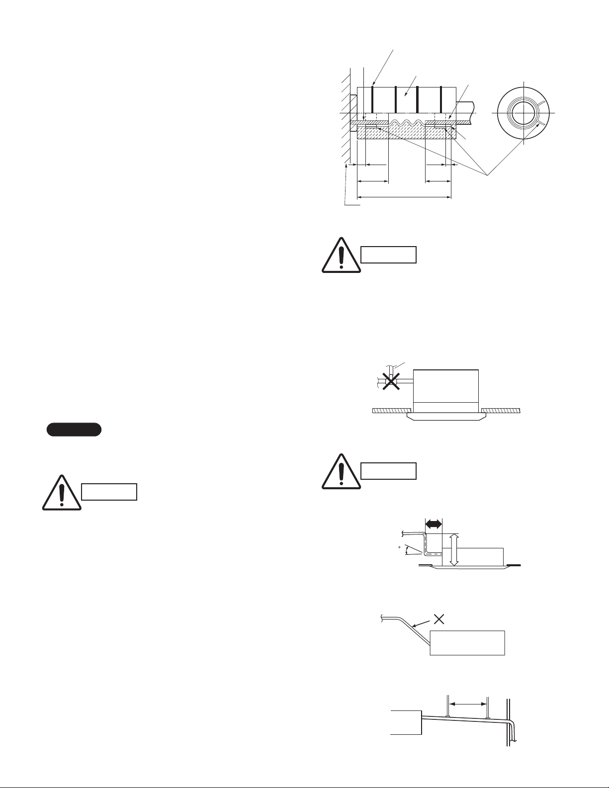
3-4. Installing the Drain Piping
(1) Prepare standard hard PVC pipe (locally purchased O.D.
1-1/32" (26 mm)) for the drain and use the supplied hose
band to prevent water leaks. (Fig. 6-5)
(2) To install the drain hose, first place 1 of the 2 hose bands
over the unit drain port and the other hose band over the
hard PVC pipe (not supplied). Then connect both ends of
the supplied drain hose. (Fig. 6-5)
(3) On the unit drain side, grasp the hose band with pliers
and insert the drain hose all the way to the base.
If other commercially available hose bands are used, the
drain hose may become pinched or wrinkled and there is
danger of water leakage. Therefore be sure to use the
supplied hose bands. When sliding the hose bands, be
careful to avoid scratching the drain hose.
Do not use adhesive when connecting the supplied drain
hose to the drain port (either on the main unit or the PVC
pipe).
Reasons: a) It may cause water to leak from the connec-
tion. Since the connection is slippery just
after the adhesive has been applied, the
pipe easily slips off.
b) The pipe cannot be removed when mainte-
nance is needed.
Twist tie
(4 vinyl ties, supplied)
3/16"
(5
mm
mm
)
Drain hose
insulation
(supplied)
)
5-1/2"(140
Drain port
15/16"
(25
Unit
CAUTION
Hard PVC pipe
(equivalent to
O.D. 1-1/32" (26mm))
(locally purchased)
3/16"
(5mm)
15/16"
(25mm)
mm
)
Drain hose
(supplied)
Hose band
(2 bands, supplied)
Position to
fasten hose
bands
Fig. 6-5
Attach so that the hose band
fastener is on the side of the
drain port.
Attach the hose bands so that
each is approximately 3/16"
(5 mm) to 15/16" (25 mm) from
the end of the supplied drain
hose.
(4) Wrap the hose with the supplied drain hose insulation
and use the 4 twist ties so that the hose is insulated with
no gaps.
Do not bend the supplied drain hose 90° or more. The
hose may slip off.
NOTE
Make sure the drain pipe has a downward gradient (1/100 or
more) and that there are no water traps.
CAUTION
In cases where it is necessary to raise the height of the
drain piping, the drain piping can be raised to a maximum
height of 2.78 ft. (850 mm) above the bottom surface of
the ceiling. Under no conditions attempt to raise it higher
than 2.78 ft. (850 mm) above the bottom surface of the
ceiling. Doing so will result in water leakage. (Fig. 6-7)
Do not use natural drainage.
Do not install the pipe with an upward gradient from the
connection port. This will cause the drain water to flow
backward and leak when the unit is not operating.
(Fig. 6-8)
Do not apply force to the piping on the unit side when
connecting the drain pipe. The pipe should not be
allowed to hang unsupported from its connection to the
unit. Fasten the pipe to a wall, frame, or other support as
close to the unit as possible. (Fig. 6-9)
Provide insulation for any pipes that are run indoors.
Air bleeder prohibited
Fig. 6-6
CAUTION
Do not install an air bleeder as
this may cause water to spray
from the drain pipe outlet.
(Fig. 6-6)
1 ft.(300mm) or less
0 - 45
* Length of supplied drain hose = 5-1/2"(140mm)
2.78 ft.(850
Fig. 6-7
Uphill slope
Fig. 6-8
Support
bracket
mm
) or less
13
Fig. 6-9
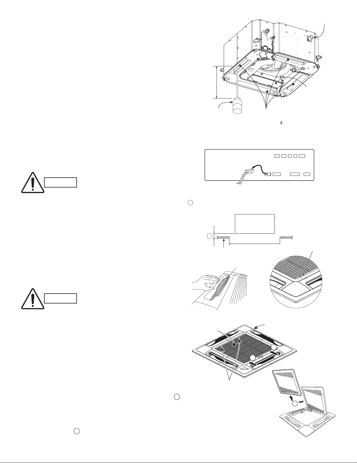
3-5. Checking the Drainage
A
After wiring and drain piping are completed, use the following procedure to check that the water will drain smoothly. For this, prepare a bucket and wiping cloth to catch and wipe up spilled water.
Be sure to do the wiring between the units before installing the
ceiling panel. (Refer to 3-9. Wiring Instructions for Inter-unit
Connections)
(1) Turn on the power. (Here, “power” refers to the power supply
from the outdoor unit.)
(2) Slowly pour approx. 16 ounces (500 ml) of water into the drain
pan to check drainage. (Fig. 6-10a)
(3) Remove the 2 screws from the control box cover, then open
the cover. Be careful not to drop the cover at this time.
(4) Disconnect the FS 3P connector (red) on the control PCB and
operate the drain pump. (Fig. 6-10b) Check the water flow
through the transparent drain pipe and see if there is any
leakage.
(5) When the check of drainage is complete, reconnect the FS
3P connector and remount the control cover.
Over 4"
(100mm)
Plastic container
for water intake
Water drain
Control box
Drain pan outlet
Water
(Approx. 16 ounces (500m ) )
Fig. 6-10a
Control box
FLAP
The drain pump will continue to
CAUTION
operate for a minimum of 6 minutes after the FS 3P connector is
reconnected.
3-6. How to Install the Ceiling Panel
Checking the unit position
(1) Check that the ceiling hole is 23-5/8" (600 mm) 23-5/8"
(600 mm) (Fig. 6-11)
(2) Confirm that the position of the indoor unit and the ceiling
as shown in the diagram. If the positions of the ceiling surface and unit do not match, air leakage, water leakage, flap
operation failure, or other problems may occur. (Fig. 6-11)
CAUTION
Never place the panel face-down. Neither hang it ver-
tically nor place it on top of a projecting object. Placing it face-down will damage the surface.
Do not touch the flap or apply force to it. (This may
cause flap malfunction.) (Fig. 6-12)
3-6-1. Before Installing the Ceiling Panel
FS
RCIND
Fig. 6-10b
must be within the range of 1/2"(13mm) to 23/32"(18mm). (Fig. 6-11)
A
If not within this range, malfunction or other trouble may occur.
Indoor unit
A
Ceiling side
Ceiling opening
dimension
Fig. 6-11
NO
Flap
Fig. 6-12 Fig. 6-13
ir-intake grille
Ceiling panel
1
1
Latch
(1) Remove the air-intake grille and air filter from the ceiling
panel.
a) Press on and slide the two latches of the air-intake grille
with your thumb in the direction shown by the arrow
to open the grille. (Figs. 6-13 and 6-14)
1
Air-intake grille hinge
Fig. 6-14
2
b) With the air-intake grille opened, remove the grille hinge
from the ceiling panel by sliding it in the direction shown
by the arrow . (Fig. 6-15)
2
Fig. 6-15
14
 Loading...