

Panasonic CU-B14DBE5, CU-J14DBE5, CS-F18DD3E5, CU-B18DBE5, CU-J18DBE5 Service Manual
...
1 SERVICE INFORMATION 3
1.1. Example of trouble at test operation
3
1.2. Caution of test operation
3
1.3. Caution during automatic address setting
3
1.4. Caution during installation
3
1.5. Operation range
3
2 FEATURES
4
2.1. Hide-away type
4
2.2. Outdoor unit
4
2.3. A brand-new control method using the latest in technology
5
3 SPECIFICATION
6
3.1. CS-F14DD3E5 CU-B14DBE5
6
3.2. CS-F18DD3E5 CU-B18DBE5
7
4 DIMENSIONS
8
© 2006 Panasonic HA Air-Conditioning (M) Sdn Bhd
(11969-T). All rights reserved. Unauthorized copying
and distribution is a violation of law.
CS-F14DD3E5 CU-B14DBE5
CS-F18DD3E5 CU-B18DBE5
4.1. CS-F14DD3E5 CS-F18DD3E5 8
4.2. CU-B14DBE5 CU-B18DBE5
9
5 REFRIGERATION CYCLE
10
5.1. CS-F14DD3E5 CU-B14DBE5 CS-F18DD3E5 CUB18DBE5
10
6 BLOCK DIAGRAM
11
6.1. CS-F14DD3E5 CS-F18DD3E5
11
6.2. CU-B14DBE5
11
6.3. CU-B18DBE5
12
7 WIRING DIAGRAM
13
7.1. CS-F14DD3E5 CS-F18DD3E5
13
7.2. CU-B14DBE5
14
7.3. CU-B18DBE5
15
8 WIRED REMOTE CONTROL OPERATING INSTRUCTIONS
16
8.1. Name and function of each part
16
Air Conditioner
CONTENTS
Page Page
ORDER NO. MAC0602013C2

8.2. Remote control - display 17
8.3. Remote control - panel
18
8.4. How to set remote control day and time
19
8.5. How to select the timer
19
8.6. Daily timer setting
20
8.7. Weekly timer setting
21
9 OPERATION DETAIL
23
9.1. Cooling operation
23
9.2. Heating operation
24
9.3. Soft dry operation
24
9.4. Auto operation
24
9.5. Fan operation
24
9.6. Normal control
25
9.7. Operation control
26
9.8. Protection control
29
9.9. Test run
31
10 INSTALLATION INSTRUCTION
32
10.1. Pipe length
32
10.2. Position of the centre gravity
33
10.3. Indoor unit installation
34
10.4. Outdoor unit installation
45
10.5. Wired remote controller installation
56
11 INSTALLATION & SERVICING AIR CONDITIONER
63
11.1. Outline
63
11.2. Tools for installing/servicing refrigerant piping
64
11.3. Refrigerant piping work
68
11.4. Installation, transferring, servicing
70
12 TROUBLE SHOOTING GUIDE
74
12.1. For standard installation
74
12.2. During twin operation
76
12.3. During group control operation
78
12.4. Test operation and self diagnosis
79
12.5. Emergency operation
82
12.6. Self-diagnosis error code table
83
13 TECHNICAL DATA
85
13.1. Sound data
85
13.2. Sound measurement point
87
13.3. Discharge and suction pressure
88
13.4. Capacity and power consumption
90
13.5. Fan performance
95
13.6. Safety device
97
13.7. Operating characteristics
98
14 REPLACEMENT PARTS
99
14.1. Indoor unit
99
14.2. Outdoor unit
101
15 PRINT PATTERN
104
15.1. Indoor unit
104
15.2. Outdoor unit
105
2
1 SERVICE INFORMATION
Notice of Address setting for NEW Duct / NEW Outdoor Unit.
The new Duct Type / New Outdoor models are possible to have address setting for twin control by automatic when main
power supply is switched on.
(Manual address setting is also possible by using Dip switch on Indoor unit P.C. board.) However,
this address setting is only
possible when made proper wiring connection and also Indoor unit should be original virgin unit
.
1.1. Example of trouble at test operation
If found out as following phenomenon at test operation on site, it may have possibility of wrong address setting.
Therefore, please ensure of the address setting.
1. LCD display of wired remote control had not illuminate although the main power supply switch is ‘on’.
2. LCD display had indicated as normal illumination when power supply switch is ‘on’, however outdoor unit cannot be operated.
(But, it is necessary to take 3 to 5 minutes for outdoor unit to start from the timing of remote control ON/OFF switch is ‘on’.)
3. P.C. board had memorized wrong setting information.
a. If main power supply is switched ‘on’ with the wrong connection.
b. When changing the connection or combination of units due to re-installation etc.
• When changing the system from twin control to normal one to one system.
• When making the replacement of units as master and slave etc.
1.2. Caution of test operation
Do not touch the remote control switch and do not change any wirings for one minute when the main power supply switch is ‘on’.
(Because the unit is having automatic address setting during the first one minute.)
1.3. Caution during automatic address setting
When main power supply switch is ‘on’, the P.C. board will automatically memorized the connecting system.
Consequently, when initial power supply is ‘on’, there will not be interchangeability of units even of the same type and same
capacity unit. Therefore unable to connect the unit to another system.
1.4. Caution during installation
To protect the compressor, after installation of new unit/pump down, be sure to select cooling mode first, and run the unit in this
mode for 5 minutes or more.
If the cooling operation is not executed first for five minutes or more, the heating operation cannot be executed.
1.5. Operation range
The applicable voltage range for each unit is given in “the following table”. The working voltage among the three phases must be
balanced within 3% deviation from each voltage at the compressor terminals. The starting voltage must be higher than 85% of the
rated voltage.
1.5.1. Power Supply
Model
CU-
Unit Main Power Applicable Voltage
Phase, Volts Hz Maximum Minimum
B14DBE5
B18DBE5
1~220 50 242 198
1~230 50 253 207
1~240 50 264 216
1.5.2. Indoor and Outdoor Temperature
Model 50Hz ... B14DBE5, B18DBE5
Operating Hz Indoor Temp. (D.B./W.B.) (°C) Outdoor Temp. (D.B./W.B.) (°C)
Maximum Minimum Maximum Minimum
Cooling 50 32/23 21/15 43/- 5/Heating 50 27/- 16/- 24/18 -10/-
3
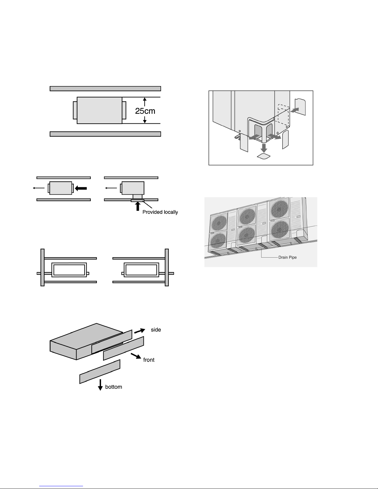
2.1. Hide-away type
2.1.1. Compact design
• The height has been reduced to 25 cm, the equipment can
be installed in limited spaces.
2.1.2. Versatile installation
• The indoor unit is designed in order that air will also enter
from below, for easier installation under different conditions.
• The equipment has two drain outlets on the right and left
side for adoption to the installation conditions in the
building.
2.1.3. Easy maintenance
• Equipped with a filter as standard. The filter can be
removed in three directions for easier maintenance.
2.2. Outdoor unit
• Long pipe design with a maximum piping length of 30m.
• Additional charging of refrigerant are not required for 20m
of pipe length.
• Flexible 4-way piping.
• Centralized drain method gather multiple outdoor units’
drain pipes into a single drain pipe to make installation
easier and also improve appearance.
• Side-by-side continuous installation is possible even for
outdoor units with different capacities.
2 FEATURES
4
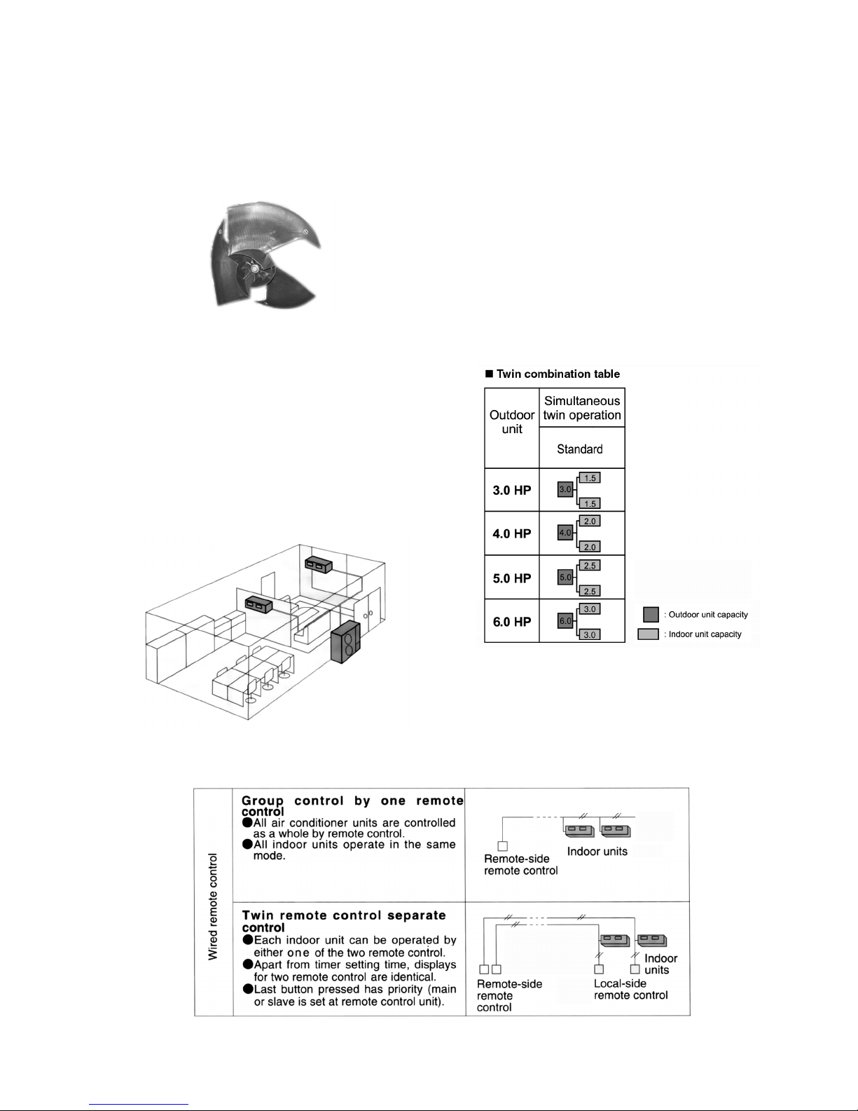
2.2.1. Quiet, efficient design
• A host of silencing technologies achieves super-quiet
operation.
• The noise-suppressing winglet fan is a result of new
research into vane design theory. The unique curved shape
suppresses the generation of vortexes, thus reduces air
flows noise.
2.3.1. Twin operation
• Simultaneous air conditioning of wide spaces and corners is
possible. Indoor units of same horsepowers and models
can even be used in combination.
• Master unit and slave-units can be set automatically in twin
systems. No address setting is necessary.
• Multiple indoor units can be operated simultaneously with a
single remote control. Note that individual operation is not
possible.
• Operating efficiency is improved and energy consumption is
reduced.
2.2.2. Low ambient cooling operation
• The unit can set for cooling even when the outdoor
temperature drops to -10°C. This is ideal for location such
as non-residential computer room (where the temperature
is not less than 21°C and humidity is not more than 45%)
that require cooling even in winter.
2.3. A brand-new control method using the latest in technology
2.3.2. Group control equipment
5
3 SPECIFICATION
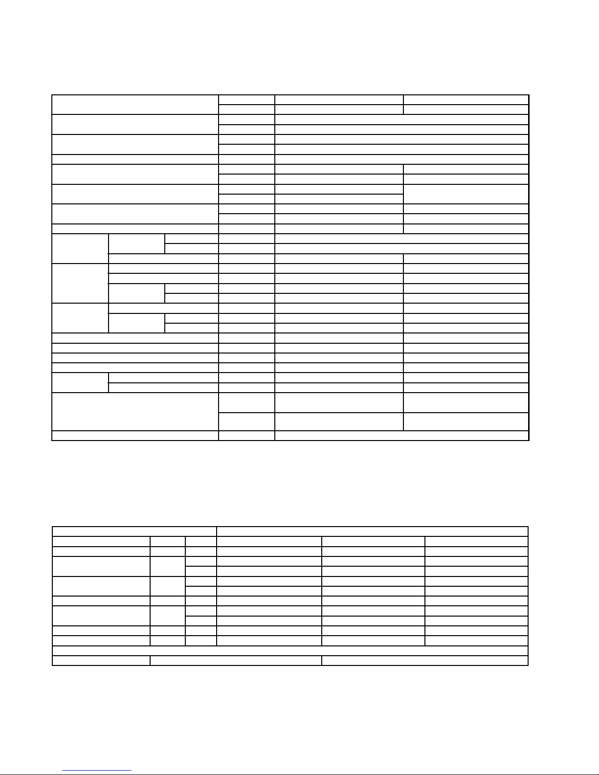
3.1. CS-F14DD3E5 CU-B14DBE5
ITEM / MODEL Indoor Unit Outdoor Unit
Main Body CS-F14DD3E5 CU-B14DBE5
Cooling Capacity kW 3.8
BTU/h 13,000
Heating Capacity kW 4.3
BTU/h 14,700
Refrigerant Charge-less m 20
Standard Air Volume for High Speed m3/min Hi 17 Hi 54
cfm Hi 600 Hi 1907
External Static Pressure Pa Hi 50 -
mmAq Hi 5.1
Outside Dimension (H x W x D) mm 250 x 880 x 650 795 x 900 x 320
inch 9-26/32 x 34-21/32 x 25-9/16 31-5/16 x 35-7/16 x 12-19/32
Net Weight kg (lbs) 34 (75) 55 (121)
Piping
Connection
Refrigerant Gas mm (inch) O.D Ø 12.7 (1/2) Flared Type
Liquid mm (inch) O.D Ø 6.36 (1/4) Flared Type
Drain mm Female screw RC1 (PT1) I.D Ø 20 x 1
Compressor Type, Number of Set - Hermetic, 1
Starting Method - Permanent Split Capacitor
Motor Type - 2-pole single phase brushless motor
Rated Output kW - 1.1
Fan Type, Number of Set Sirocco fan, 2 Mix flow fan - 1
Motor Type 4-pole single phase induction motor 6-pole single phase induction motor
Rated Output kW 0.085 0.07
Air-heat Exchanger (Row x Stage x FPI) Louvre-fin type (3 x 12 x 15) Corrugate-fin type (1 x 36 x 21)
Refrigerant Control - Exp. Valve
Refrigerant Oil (Charged) cm
3
- FV50S (670)
Refrigerant (Charged) R410A kg (oz) - 1.1 (38.8)
Running
Adjustment
Control Switch Wired Remote Control Room Temperature Thermostat -
Noise Level dB (A) Cooling : Hi 42 Lo 38 Cooling 49, Heating 50
Heating : Hi 42 Lo 38
Power level dB Cooling : Hi 58 Lo 54
Heating : Hi 58 Lo 54
Cooling 65, Heating 66
Moisture Removal L/h (Pt/h) 2.2 (4.6)
1. Cooling capacities are based on indoor temperature of 27°C D.B. (80.6°F D.B.), 19.0°C W.B. (66.2°F W.B.) and outdoor air
temperature of 35°C D.B. (95°F D.B.), 24°C W.B. (75.2°F W.B.)
2. Heating capacities are based on indoor temperature 20°C D.B. (68°F D.B.) and outdoor air temperature of 7°C D.B. (44.6°F
D.B.), 6°C W.B. (42.8°F W.B.)
ELECTRICAL DATA (50 Hz)
ITEM / MODEL Condition by ISO5151
Volts V 220 230 240
Phase Single Single Single
Power Consumption kW Cool 1.32 1.35 1.38
Heat 1.18 1.21 1.24
Running Current A Cool 6.31 6.21 6.11
Heat 5.46 5.36 5.26
Starting Current A 23 24 25
Power Factor % Cool 95 95 94
Heat 98 98 98
EER W/W 2.88 2.81 2.75
COP W/W 3.64 3.55 3.47
*Power Factor means total figure of compressor, indoor fan motor and outdoor fan motor.
Panasonic Power source AC, 1~220V, 230V, 240V 50Hz
6
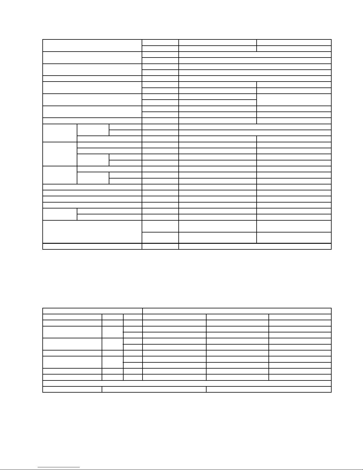
3.2. CS-F18DD3E5 CU-B18DBE5
ITEM / MODEL Indoor Unit Outdoor Unit
Main Body CS-F18DD3E5 CU-B18DBE5
Cooling Capacity kW 5.0
BTU/h 17,100
Heating Capacity kW 5.6
BTU/h 19,100
Refrigerant Charge-less m 20
Standard Air Volume for High Speed m3/min Hi 17 Hi 57
cfm Hi 600 Hi 2013
External Static Pressure Pa Hi 50 -
mmAq Hi 5.1
Outside Dimension (H x W x D) mm 250 x 880 x 650 795 x 900 x 320
inch 9-26/32 x 34-21/32 x 25-9/16 31-5/16 x 35-7/16 x 12-19/32
Net Weight kg (lbs) 34 (75) 57 (126)
Piping
Connection
Refrigerant Gas mm (inch) O.D Ø 12.7 (1/2) Flared Type
Liquid mm (inch) O.D Ø 6.36 (1/4) Flared Type
Drain mm Female screw RC1 (PT1) I.D Ø 20 x 1
Compressor Type, Number of Set - Hermetic, 1
Starting Method - Permanent Split Capacitor
Motor Type - 2-pole single phase brushless motor
Rated Output kW - 1.5
Fan Type, Number of Set Sirocco Fan, 2 Mix flow fan - 1
Motor Type 4-pole single phase induction motor 6-pole single phase induction motor
Rated Output kW 0.085 0.07
Air-heat Exchanger (Row x Stage x FPI) Louvre-fin type (3 x 12 x 15) Corrugate-fin type (1 x 36 x 21)
Refrigerant Control - Exp. Valve
Refrigerant Oil (Charged) cm
3
- FV50S (670)
Refrigerant (Charged) R410A kg (oz) - 1.35 (47.6)
Running
Adjustment
Control Switch Wired Remote Control Room Temperature Thermostat -
Noise Level dB (A) Cooling : Hi 42 Lo 38 Cooling 49, Heating 50
Heating : Hi 42 Lo 38
Power level dB Cooling : Hi 58 Lo 54
Heating : Hi 58 Lo 54
Cooling 65, Heating 66
Moisture Removal L/h (Pt/h) 2.8 (5.9)
1. Cooling capacities are based on indoor temperature of 27°C D.B. (80.6°F D.B.), 19.0°C W.B. (66.2°F W.B.) and outdoor air
temperature of 35°C D.B. (95°F D.B.), 24°C W.B. (75.2°F W.B.)
2. Heating capacities are based on indoor temperature of 20°C D.B. (68°F D.B.) and outdoor air temperature of 7°C D.B. (44.6°F
D.B.), 6°C W.B. (42.8°F W.B.)
ELECTRICAL DATA (50 Hz)
ITEM / MODEL Condition by ISO5151
Volts V 220 230 240
Phase Single Single Single
Power Consumption kW Cool 1.86 1.89 1.92
Heat 1.67 1.70 1.73
Running Current A Cool 8.73 8.53 8.33
Heat 7.83 7.63 7.43
Starting Current A 26 27 28
Power Factor % Cool 97 96 96
Heat 89 91 93
EER W/W 2.67 2.66 2.63
COP W/W 3.35 3.29 3.24
*Power Factor means total figure of compressor, indoor fan motor and outdoor fan motor.
Panasonic Power source AC, 1~220V, 230V, 240V 50Hz
7
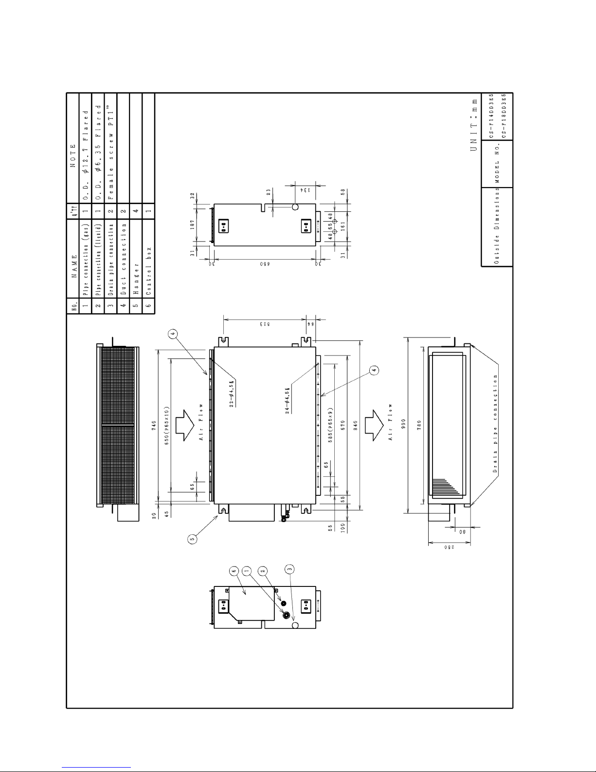
4 DIMENSIONS
4.1. CS-F14DD3E5 CS-F18DD3E5
8
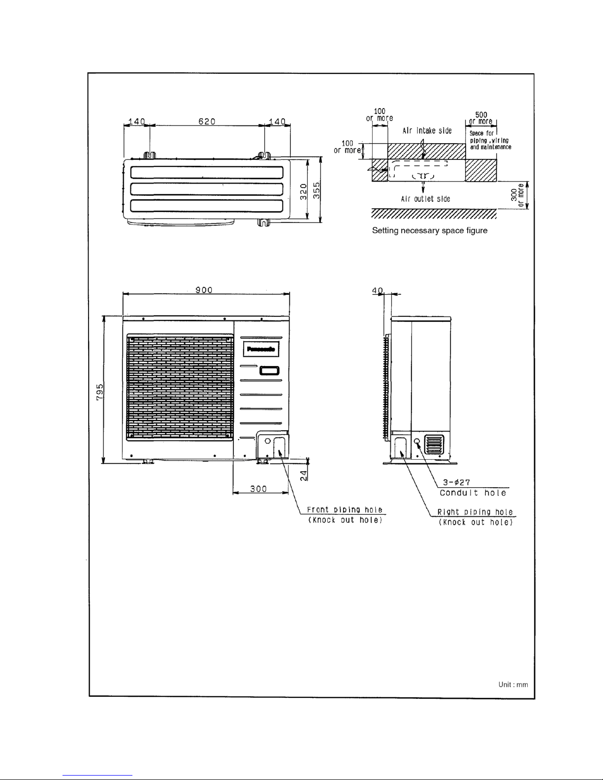
4.2. CU-B14DBE5 CU-B18DBE5
9

5 REFRIGERATION CYCLE
5.1. CS-F14DD3E5 CU-B14DBE5
CS-F18DD3E5 CU-B18DBE5
10

6 BLOCK DIAGRAM
6.1. CS-F14DD3E5 CS-F18DD3E5
6.2. CU-B14DBE5
11
6.3. CU-B18DBE5
12

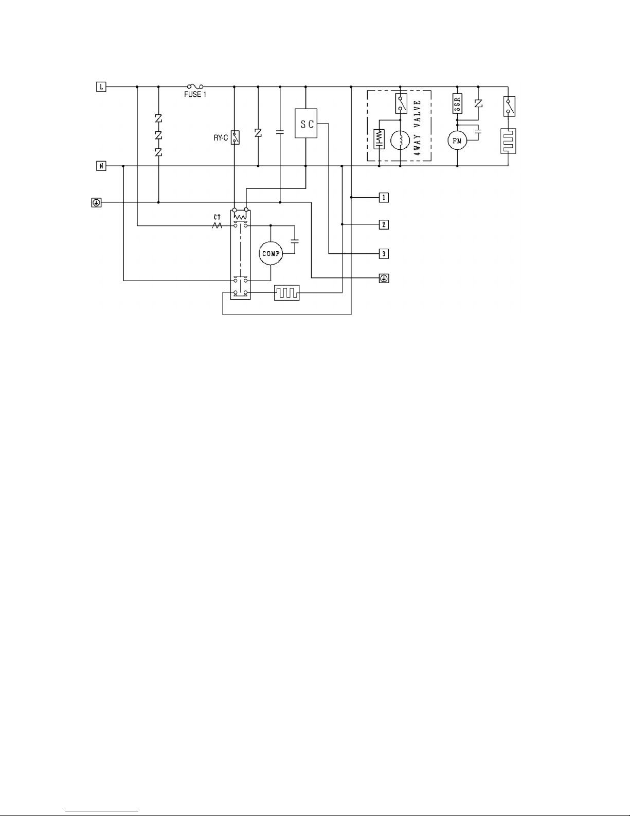
7 WIRING DIAGRAM
7.1. CS-F14DD3E5 CS-F18DD3E5
13

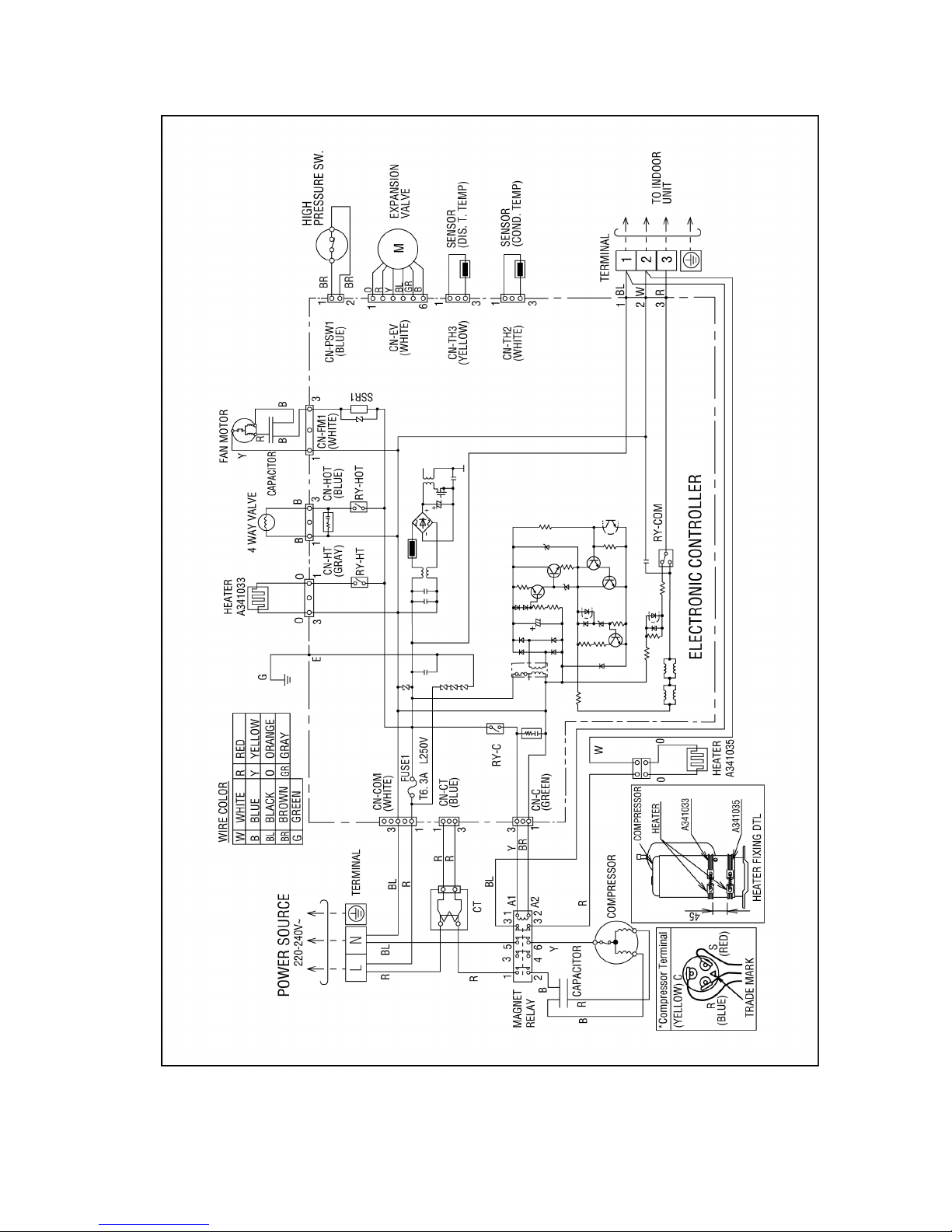
7.2. CU-B14DBE5
14
7.3. CU-B18DBE5
15

REMOTE
The OFF/ON button cannot be used.
LOCAL
All wired remote control buttons can be used.
Time/time setting display
Check display
Fan speed display
Operation mode selection display
FILTER RESET display
(Appears after the cumulative running time reaches
approximately 2,500 hours of operation.)
Temperature setting display (16°C - 31°C)
Airflow direction setting display
OFF/ON button
Used to start and stop the operation.
FAN SPEED button
Used to select the fan speed of high (HI), medium (MED), low
(LO) or auto (AUTO).
MODE button
Used to select the operation of AUTO, HEAT, FAN, COOL, or
DRY.
TEMP (UP/DOWN) buttons
Used to select the desired temperature.
AIR SWING (AUTO/MANUAL) buttons
Used to determined the air swing condition, either auto or
manual.
FILTER RESET button
Press to reset the “FILTER RESET” display after washing the
filter.
TEST RUN button*
VENTILATION button*
ECONOMY operation button
Provides Energy saving function
ODOUR WASH button
Provides deodorizing function.
CHECK button
Press this button if the check display is flashing.
TIMER/CLOCK SET buttons
Used to set the timer operation and the current time.
Operation indicator
Lights up when the unit in operation.
8 WIRED REMOTE CONTROL OPERATING INSTRUCTIONS
8.1. Name and function of each part
NOTES
•
Ensure that the correct button is pressed as simultaneous pressing of the multiple buttons will not make the setting correct.
•
The illustration above is for explanatory purposes only. The appearance will be different during actual operation.
•
Do not operate the remote control with wet hands. Otherwise, electric shock or malfunction may occur.
•
Do not press the remote control buttons with sharp object as this may damage the remote control.
•
Buttons marked with * are not needed for normal operation. If one of these buttons is pressed by mistake, press the same
button once more to cancel the operation.
•
When the power resumed after power failure, the unit will restart automatically with all the previous settings preserved by
the memory function. (Auto restart function)
•
Buttons marked with
are not available for operation. If one of these buttons is pressed function will not be available.
16
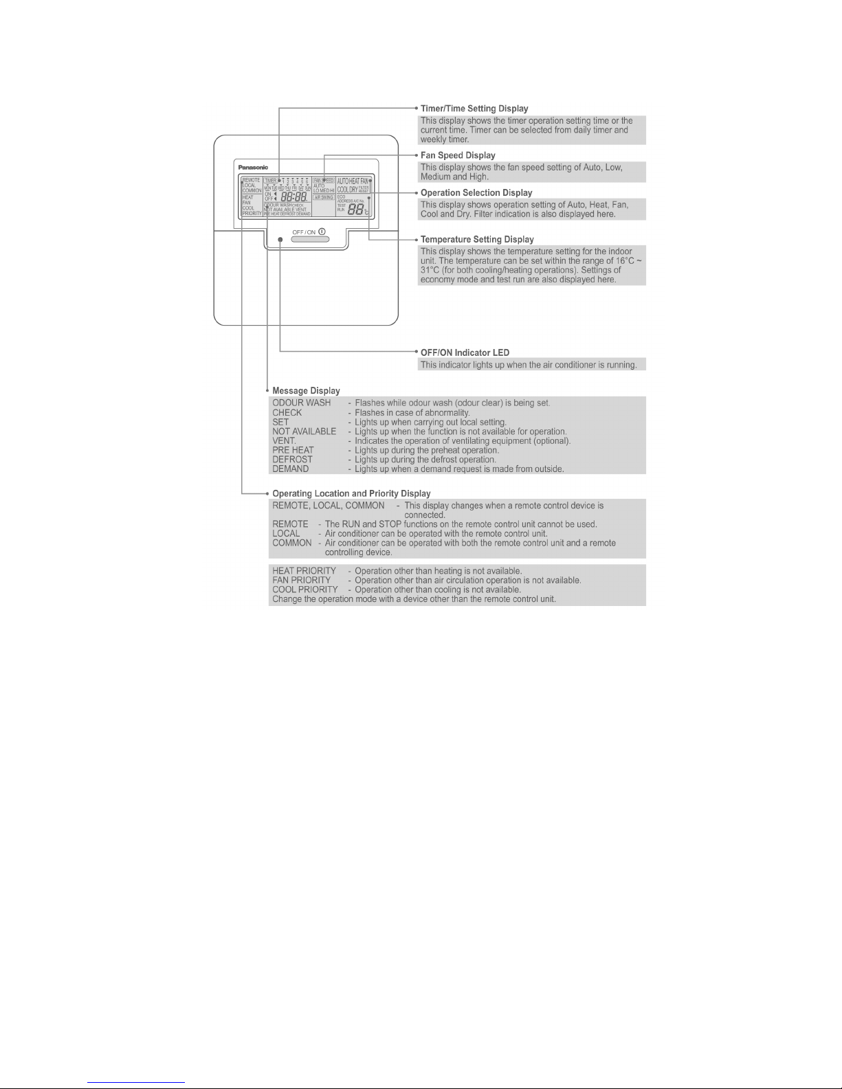
8.2. Remote control - display
17
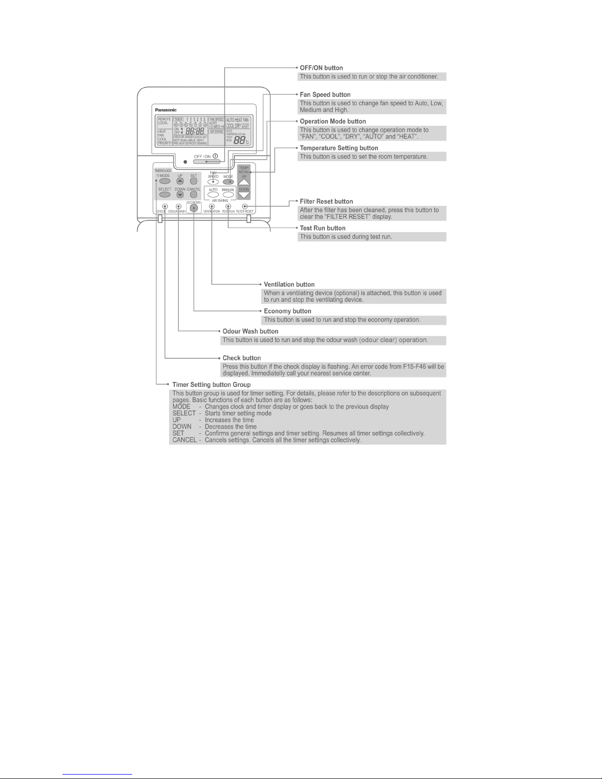
8.3. Remote control - panel
18
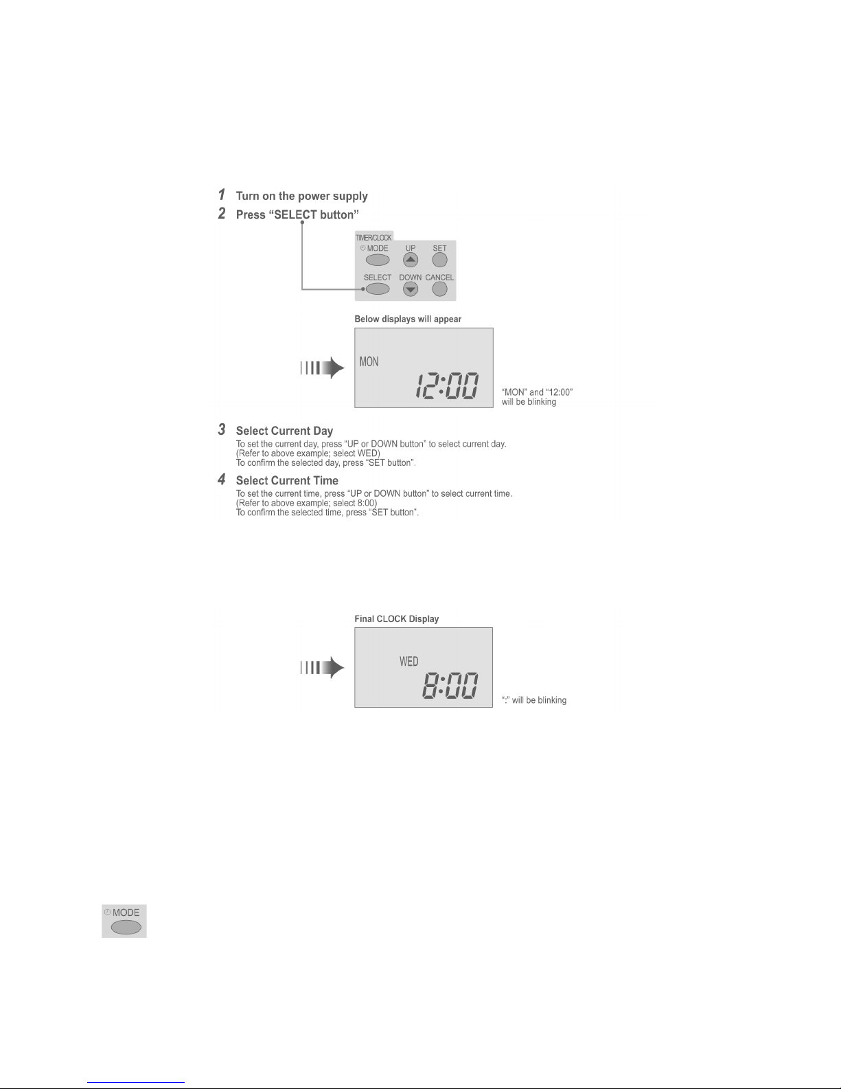
8.4. How to set remote control day and time
• The day and time need to be set when you turn on the power for the first time or after a long time has elapsed since the power
was last turned on.
• The day and time become the standard time for all the Timer operations.
• Set the day and time accurately.
• Example : Current Day is Wednesday and Current Time is 8:00.
Note:
• Press “UP button” to increase or “DOWN button” to decrease (interval 1 minute) or hold the button to change the time faster.
• If the “UP or DOWN button” is not pressed for 30 seconds during the day or time setting or if the “SELECT button” is
pressed, the setting at that moment is confirmed and setting will end.
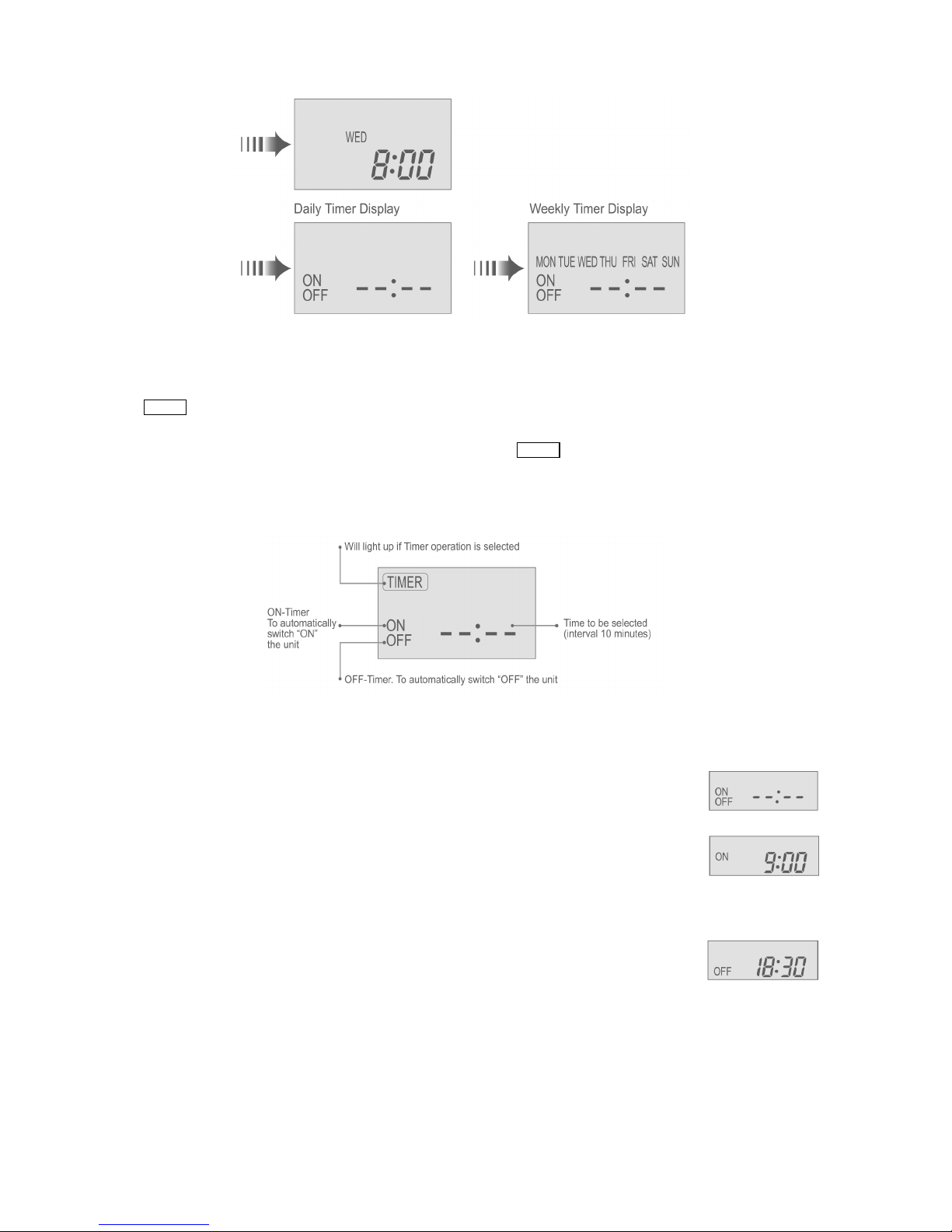
8.5. How to select the timer
• 2 types of Timer mode can be selected on the remote control.
− Daily Timer
− Weekly Timer
• These timers cannot be operated simultaneously.
• Select one of these Timers for your convenience.
How to Change the Display
• Press once to change the display from CLOCK to Timer or vice-versa.
• Press more than 3 seconds to change the display from Daily Timer to Weekly Timer or vice-versa.
19
CLOCK Display (To set current Day and Time)
Note:
• The above display is shown if no valid timer setting is made.
• If valid timer setting is made.
− Timer
and setting will be displayed.
− If you want to check the current time and day, press “MODE button” once.
(However, after a few seconds, the display will change back to Timer
and the setting)
8.6. Daily timer setting
• Display
• How to Set Daily Timer
− You can set only “ON” or only “OFF” or “ON” and “OFF” in a day.
1. Change Display
Press “MODE button” to change the display to daily timer.
2. ON-Timer, OFF-Timer and select Time
Press “SELECT button”; ON-Timer setting will be displayed.
Press “UP or DOWN button” to select the desired time, (Example: ON 9:00), then press “SET button” to confirm
the selected desired time.
Or press “CANCEL button” if you do not want any setting for ON-Timer.
Then OFF-Timer setting will be displayed.
Press “UP or DOWN button” to select the desired time, (Example: OFF 18:30), then press “SET button” to
confirm the selected desired time.
Or press “CANCEL button” if you do not want any setting for OFF-Timer.
Note:
• The setting timer will be activated everyday.
• Timer nearer to the current time will be activated first.
20
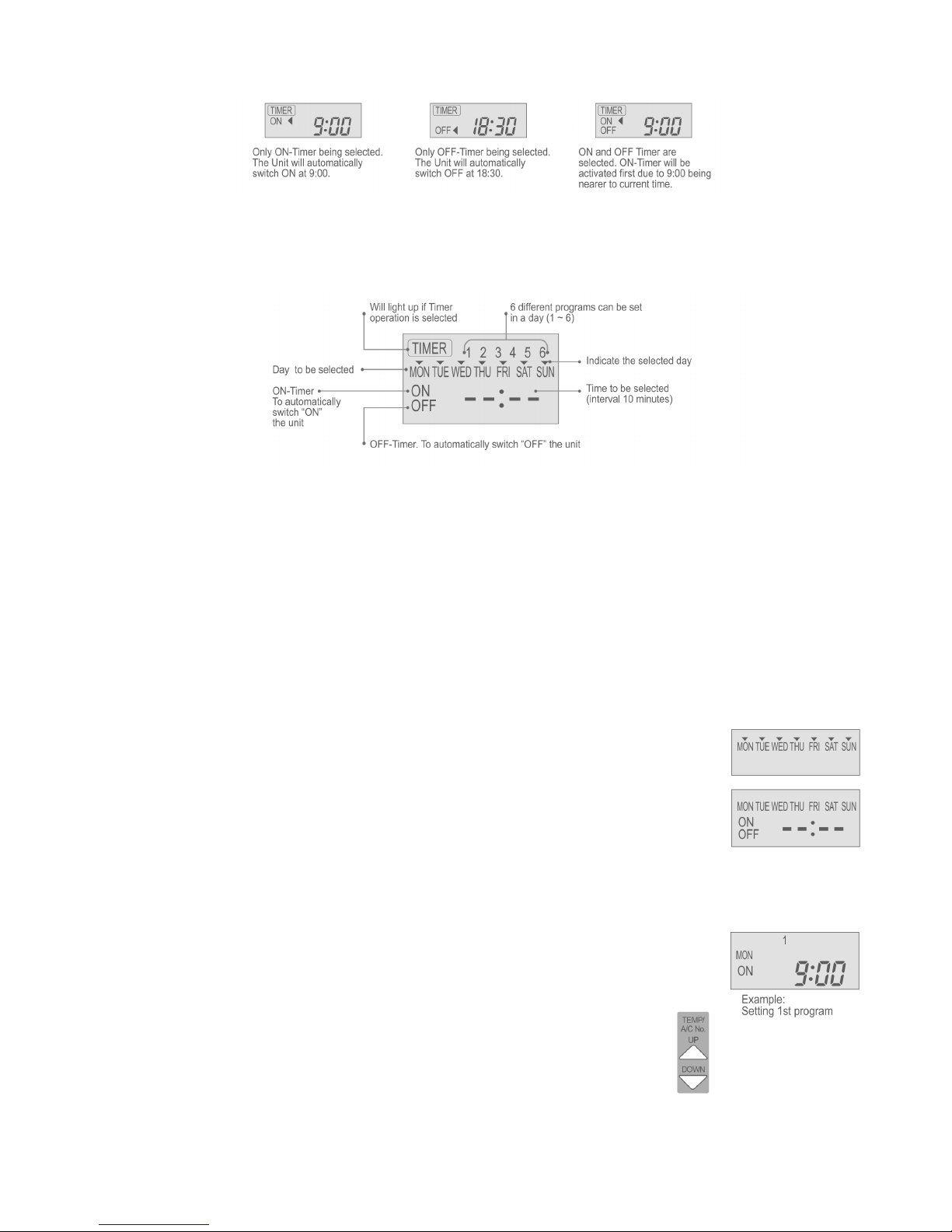
Final Display of Daily Timer:
8.7. Weekly timer setting
• Display
• How to Set Weekly Timer
− You can set the Timer for 1 week (Monday to Sunday) with 6 programs per day.
− ON-Timer can be set together with your desired temperature. However, this temperature will be used continuously.
− Cannot set 2 programs with same time setting in a day.
− You also may select Collective - many days with same time setting or Individual
− single/one day setting.
1. Change Display
Press “MODE button” to change the display to weekly timer.
2. Select Day (please refer to next page for example of setting)
You may select Collective or Individual day setting.
•
Collective day setting.
Press “SELECT button”: display will show day selection setting.
Press “UP or DOWN button” to select the day. Then press “SET button” to delete triangle mark
(deselect) or add triangle mark (select).
(Triangle mark on top of each day indicates the day to be selected).
Repeat these steps if you want to deselect or select many days.
To confirm the selected days, press the “SELECT button”.
•
Individual day setting.
Press “UP or DOWN button” to select the day.
Then press “SELECT button”.
3. Select Time (please refer to next page for example of setting)
For 1st program setting.
Press “UP or DOWN button” to select ON or OFF.
Then press “SET button” to confirm.
Press “UP or DOWN button” again to select the desired time.
(If you want to set them together with your desired temperature, press “TEMP UP/DOWN button” to
select the temperature).
Then press “SET button” to confirm.
Or press “CANCEL button” if you do not want to set any time.
For 2nd ~ 6th program you may refer to the above step.
21
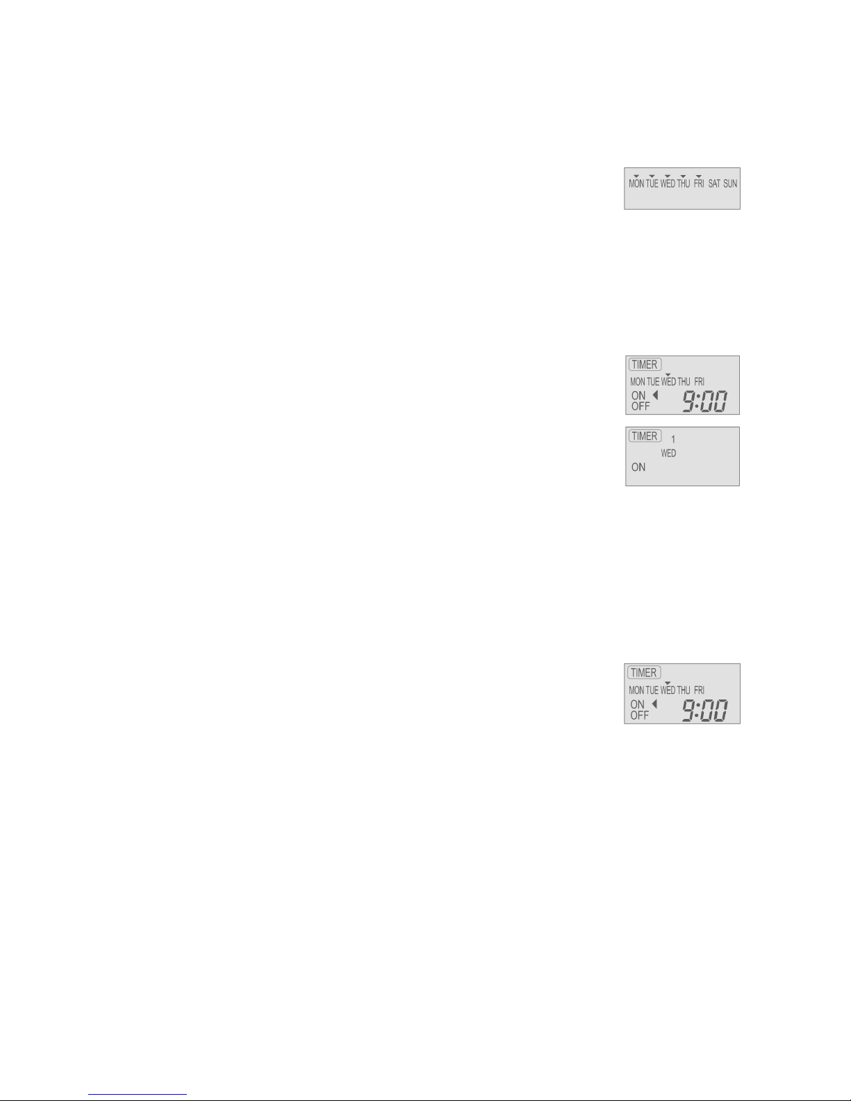
For example, if you want to set:
A - Monday to Friday: Same time, 1st program ON 9:00 & 2nd program OFF 16:00.
B - Only Wednesday: Additional 3rd program OFF 12:30 & 4th program ON 13:30.
C - Only Saturday: 1st program ON 10:00 with 20°C & 2nd program OFF 14:00.
D - Sunday: Holiday. No need to set any Timer.
•
To set A (Monday to Friday - Collective day setting)
Press “SELECT button”
To select Monday to Friday, deselect Saturday and Sunday by pressing “UP or DOWN button” to Saturday, press
“SET button” (triangle mark on top of Saturday will disappear)
Follow the same step to deselect Sunday.
Ensure triangle mark appears on top of Monday ~ Friday.
−
To confirm the selected days, press “SELECT button”.
To set the time, please refer to step 3.
−
1st program - select ON and desired time to 9:00.
2nd program - select OFF and desired time to 16:00.
3rd ~ 6th program - press “CANCEL button”.
•
To set B (Wednesday - Individual day setting)
−
Press “UP or DOWN button” to select WED (Wednesday).
Then press “SELECT button”.
To set the time, please refer to step 3.
−
1st program - press “SET button” twice (confirm ON and 9:00)
2nd program - also press “SET button” twice. (Confirm OFF and 16:00)
3rd program - select OFF and desired time to 12:30
4th program - select ON and desired time to 13:30
5th ~6th program - press “CANCEL button”
•
To set C (Saturday - Individual day setting)
−
Follow the same step as above.
To set the time, please refer to step 3.
−
1st program - select ON, desired time to 10:00 and desired temperature to 20°C.
2nd program - select OFF and desired time to 14:00.
3rd ~ 6th program - press “CANCEL button”.
−
Final Display for Weekly timer may show as:
(Display is showing, 9:00 ON - Timer on Wednesday will be activated next because it is nearest the current
day/time.)
Note:
• Timer that has setting nearest to current time and day will be activated first.
• To check the setting timer, press “SELECT button”, then “UP or DOWN button” to select day. The display will show each
program for the selected day.
• To reset the setting for all, press “SELECT button”, then ensure all day setting with triangle mark. Then press “CANCEL
button” for all the programs.
22
9 OPERATION DETAIL
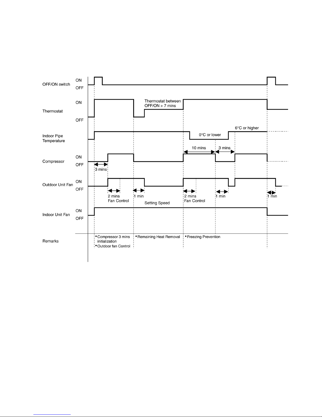
9.1. Cooling operation
• Cooling operation can be set using remote control.
• This operation is applied to cool down the room temperature reaches the setting temperature set on the remote control.
• Cooling Operation Time Diagram.
23
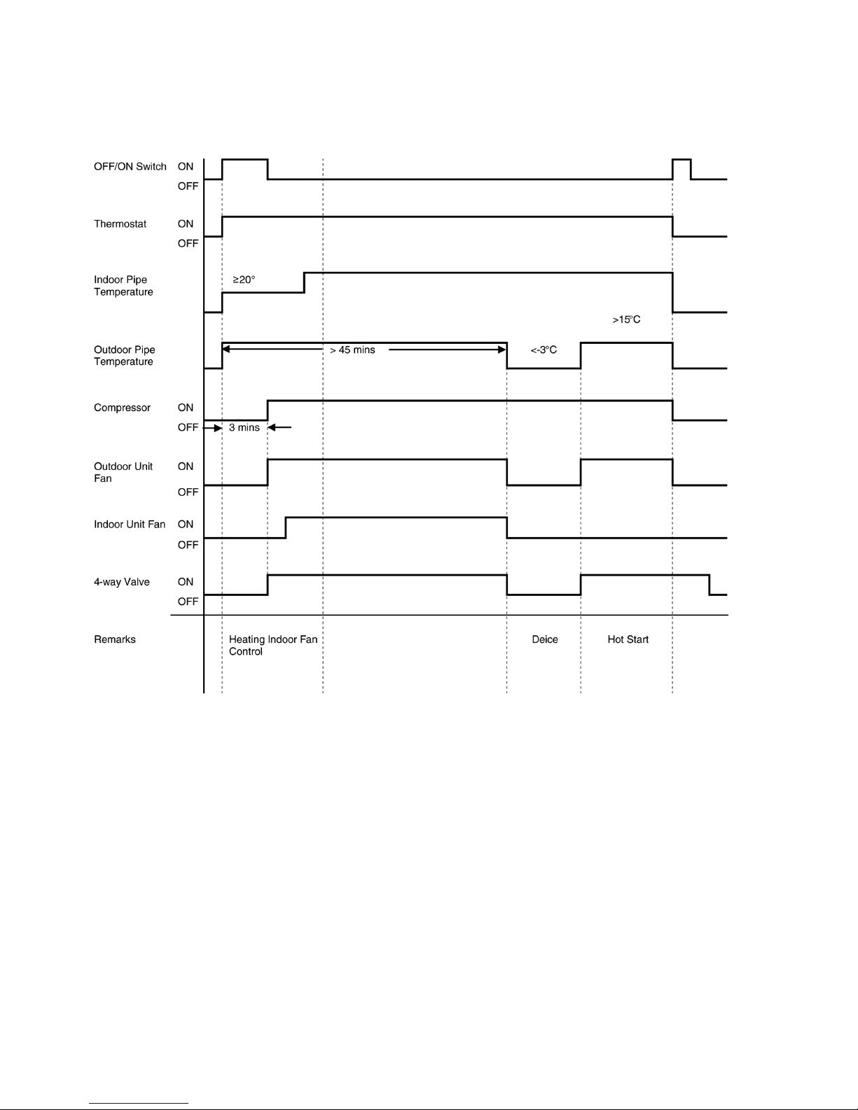
9.2. Heating operation
• Heating operation can be set using remote control.
• This operation is applied to warm up the room temperature reaches the setting temperature set on the remote control.
• Heating Operation Time Diagram.
9.3. Soft dry operation
• Soft Dry Operation can be set using remote control.
• Soft Dry operation is applied to dehumidify the room.
• When operation begins, the fan speed is fixed at Low speed while cooling operation is running until reaches the remote control
setting temperature.
9.4. Auto operation
• Automatic Mode can be set using remote control.
• This operation starts to judge the intake air temperature, setting temperature, and outdoor piping temperature. Then the unit
starts to operate at determined operation mode.
9.5. Fan operation
• Fan operation can be set using remote control.
• The indoor fan is operated at High, Medium or Low speed according to remote control setting.
24
9.6. Normal control
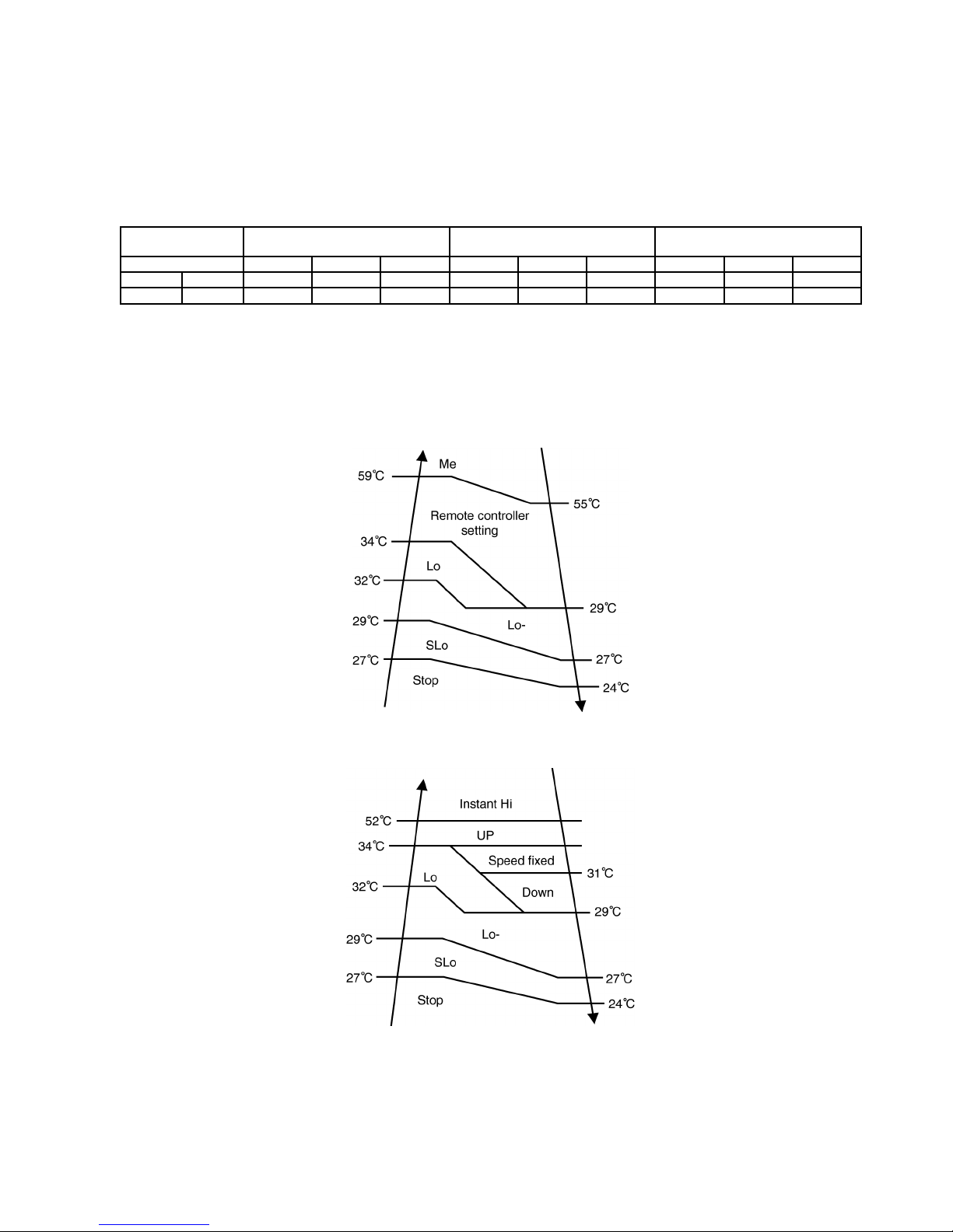
9.6.1. Cooling Indoor Fan Control
• Manual Fan Speed
Operation starts at High, Medium or Low speed set by remote control.
• Auto Fan Speed
When operation starts, or shifting to thermostat ON condition from thermostat OFF condition, indoor fan operates as below.
Thermostat &
Compressor ON/OFF
Thermostat & Compressor ON Thermostat & Compressor OFF Thermostat & Compressor ON
Time 40 sec. 50 sec. - 20 sec. 120 sec. 20 sec. 40 sec. 50 sec. -
Cool Auto Off Lo Hi Lo Off Lo Off Lo Me
Soft Dry Auto Off Lo Lo Lo Off Lo Off Lo Lo
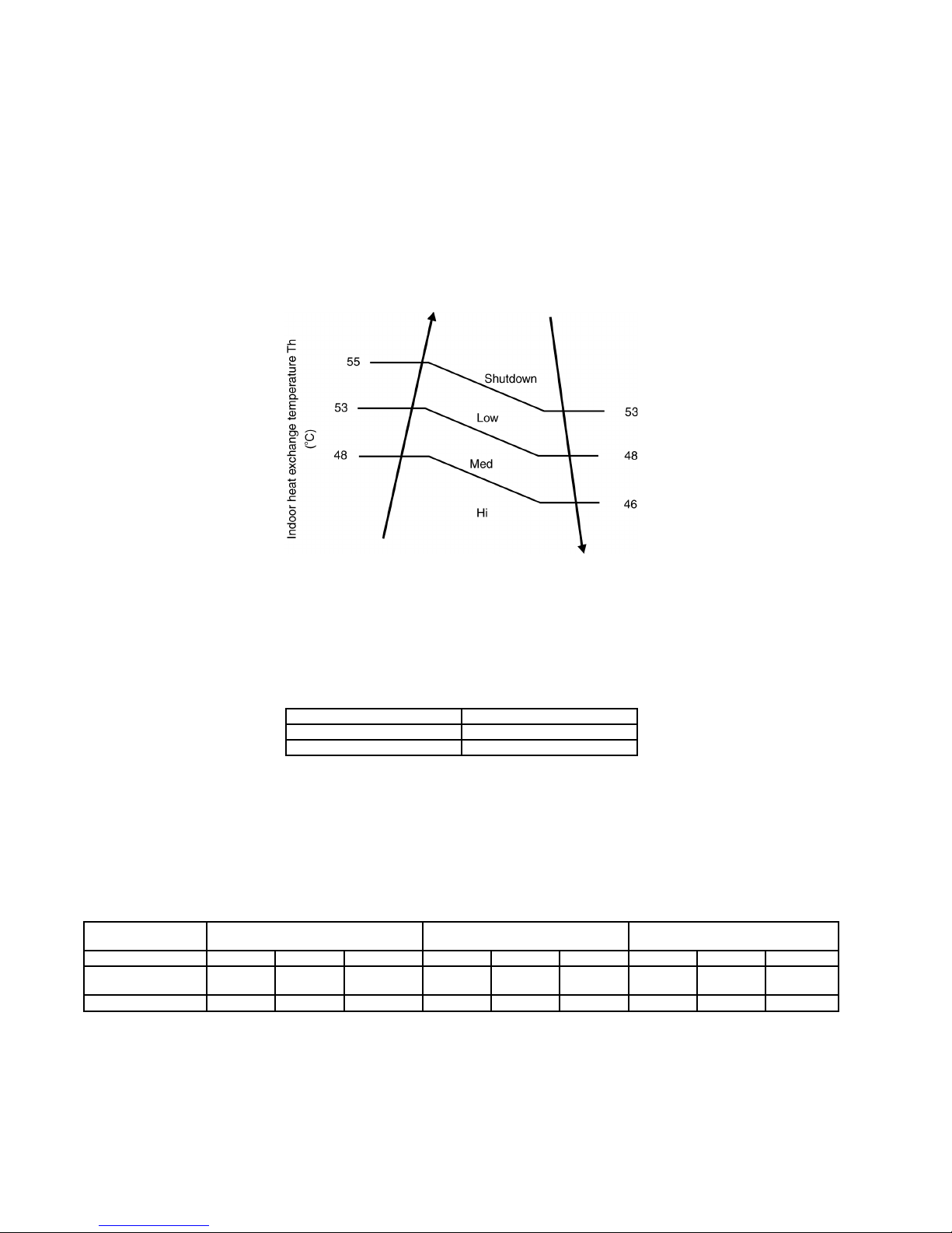
9.6.2. Heating Indoor Fan Control
• Manual Fan Speed
Operation starts at High, Medium or Low speed set by remote control.
However, when operation start, or during operation, fan speed control is limited due to prevent a cold draft, for example, when
heating operation start.
• Auto Fan Speed
When operation start, or during operation, fan speed control by detecting indoor heat exchanger as follows:
• If thermostat is off, indoor fan fixed low speed.
25
9.6.3. Cooling Outdoor Fan Control
• During cooling operation, outdoor fan speed changes according to outdoor pipe temperature.
• The fan speed is controlled by the timing of turning the outdoor fan ON and OFF within an interval.
• When outdoor pipe temperature increases, internal timing also increases.
• Outdoor fan ON time is a variable with the range of 200ms to 2000ms.
• After 2 minutes, the outdoor pipe temperature is detected and the outdoor unit fan speed is changed automatically.
9.6.4. Heating Outdoor Fan Control
• During heating operation, the fan speed is controlled by indoor heat exchanger temperature.
• In case of twin operation, the higher indoor heat exchanger temperature is used to control the fan speed. During heating
operation, the fan speed is controlled by indoor heat exchanger temperature.
9.7. Operation control
9.7.1. Thermostat Control
• Depending on differences between room temperature and setting temperature, compressor operation is decided and starts
operation.
• If temperature difference matches values shown below, thermostat switches off.
Cool Mode -1.5°C
Soft Dry Mode -2.5°C
Heat Mode 3.5°C
9.7.2. Odour Cut Control
• Odour cut operation removes the odour generated at indoor heat exchanger by using drain water come out from indoor heat
exchanger.
• Press “Odour” button at remote control to enable odour cut operation.
• Odour cut operation starts when compressor or thermostat is on.
Thermostat &
Compressor ON/OFF
Thermostat & Compressor ON Thermostat & Compressor OFF Thermostat & Compressor ON
Time 40 sec. 50 sec. - 20 sec. 120 sec. 20 sec. 40 sec. 50 sec. -
Cool Off Lo Normal
Operation
Lo Off Lo Off Lo Normal
Operation
Soft Dry Off Lo Lo Lo Off Lo Off Lo Lo
9.7.3. Hot Start Control
• Hot start control operates at the starting of heating operation, where [PREHEAT] displayed at wired remote control.
• Indoor fan stops until hot start control ends (indoor heat exchanger temperature increases or 4 minutes past heating operation
starts), fan control resume.
26
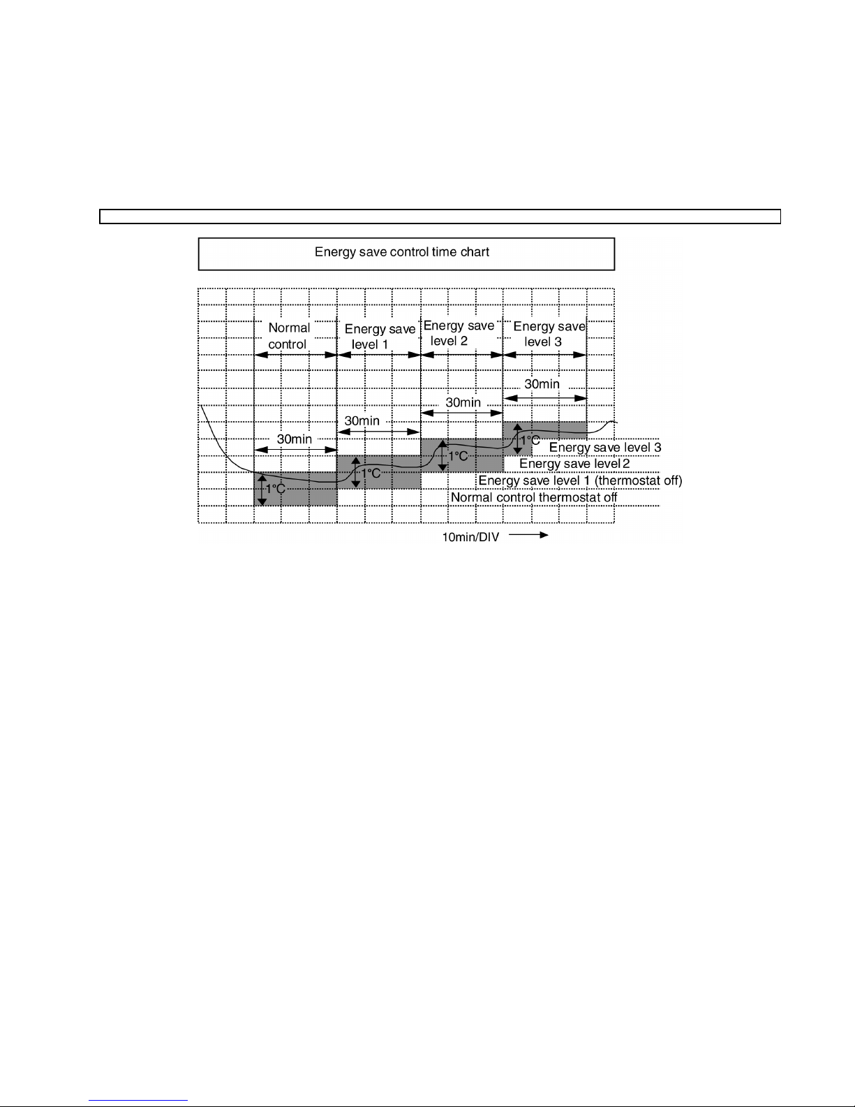
9.7.4. Energy Save Control
• During Cooling Operation, press "Economy" button at remote control to enable Energy Saving Operation.
• The air conditioner judges the stable condition, where the different between indoor suction temperature and setting temperature
is 1°C for 30 minutes and moderately shifts the set temperature in 0.5°C steps (Maximum 2°C) to control energy saving
operation.
• If temperature different is out of range, energy save operation will not start.
• Energy Save Operation is canceled by pressing the "Economy" button again.
Energy save control time chart
9.7.5. Dew Form Prevention Control
• During cool or dry operation, if outdoor temperature is less than 30°C, and indoor fan speed is low or auto setting, indoor heat
exchanger temperature become lower, dew form prevention control start to prevent dew form at indoor discharge grill.
• When indoor pipe temperature decrease, cooling capacity will be reduced.
9.7.6. Freeze Prevention Control
• During Cooling or Dry operation, after compressor starts operation for 4 minutes, the outdoor unit will stop its operation if indoor
pipe temperature falls below 0ºC for 6 minutes.
• After 3 minutes stops, compressor restarts operation if indoor pipe temperature is 6ºC or more.
• This phenomenon is to protect the indoor heat exchanger from freezing and to prevent higher volume of refrigerant in liquid from
returning to the compressor.
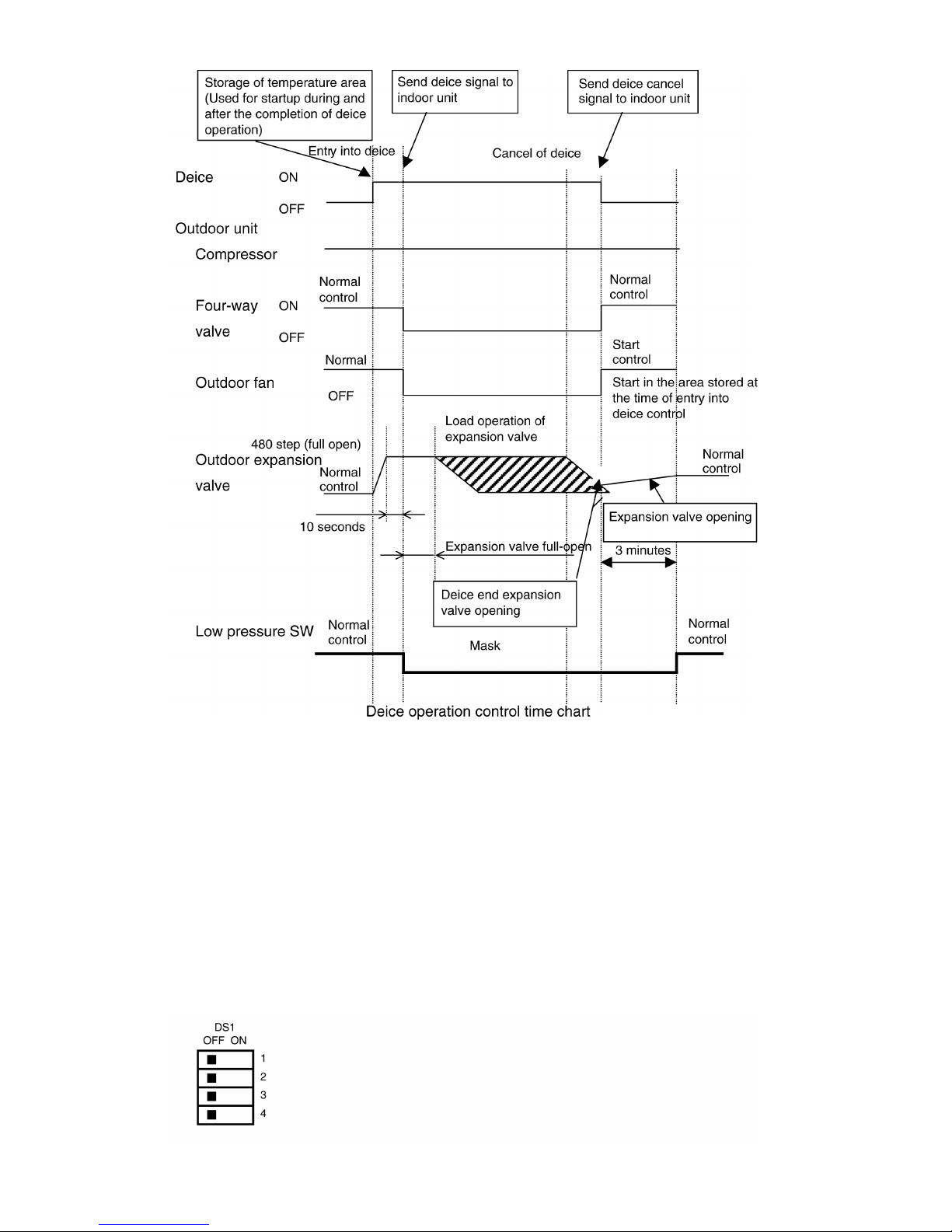
9.7.7. Deice Control
• During heating operation at low outdoor temperature, deice operation start timely to melt the ice formed on outdoor heat
exchanger.
• During deice operation, in spite of any changes of remote control, indoor fan stop.
• During deice operation, [DEFROST] is displayed at wired remote control, hot start operate after deice operation finish.
• Deice operation start when accumulative heating operation time or after previous deice end reaches 45 minutes, the outdoor
fan maintains Hi status and the outdoor heat exchanger maintains -2°C for 5 minutes.
27
9.7.8. Time Delay Safe Control
• The compressor will not start for three minutes after stop of operation.
9.7.9. Outdoor Fan Remaining Heat Removal Control
• When compressor stops, outdoor fan operates at High speed for 1 minute to remove the remaining heat.
9.7.10. Crank Case Heater Control
• Crank case heater ON when the compressor is shutdown and discharge temperature is 20°C to prevents the refrigerant solving
into compressor oil inside the compressor shell at cold condition.
9.7.11. Pump Down
• To enable pump down operation, at outdoor PCB, set the DS1 to OFF position.
28
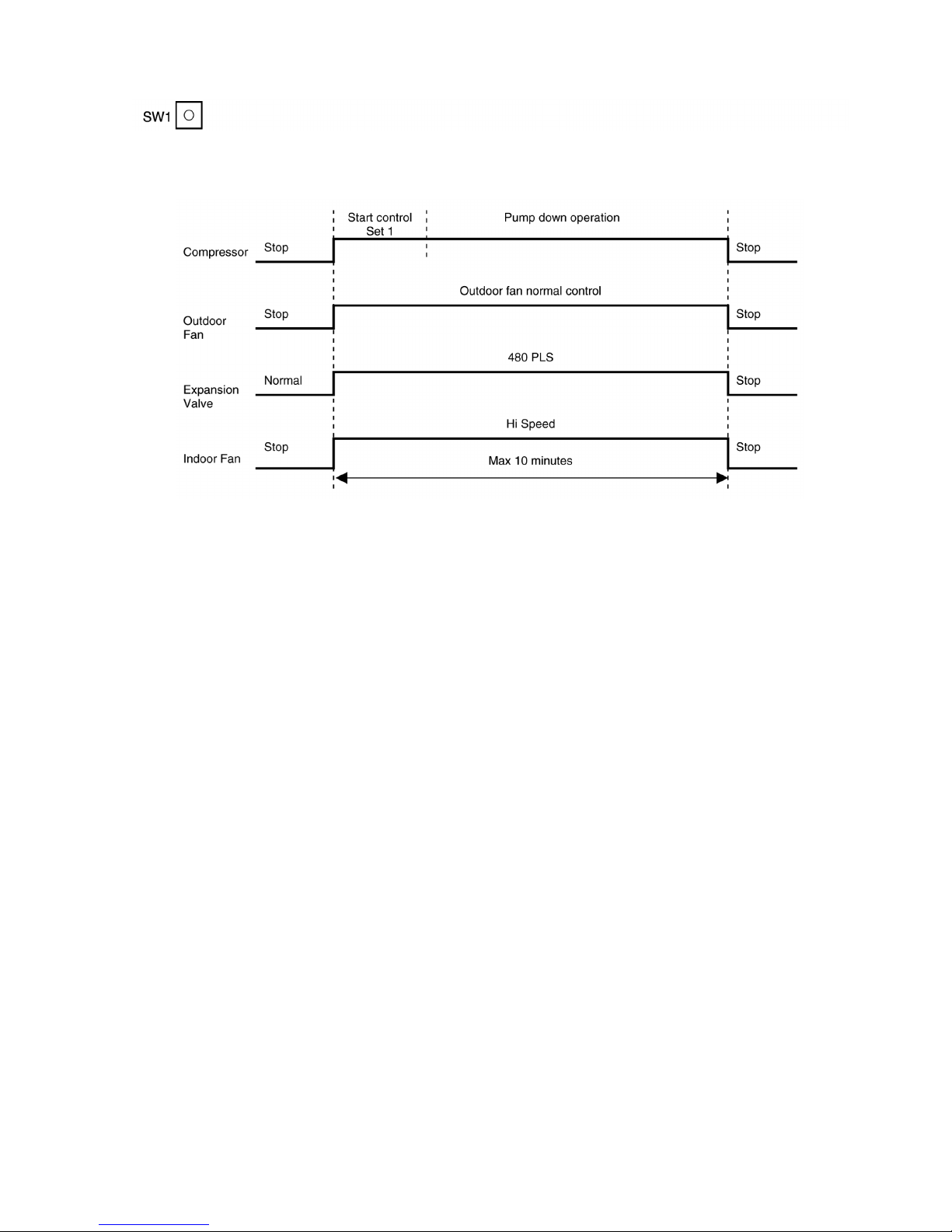
• Press Test Run button for 1 second. SW1 located at outdoor printed circuit board.
• During Pump Down operation, push the Test Run button again for 1 second to stop the pump down operation.
• The pump down operation runs for 10 minutes.
9.8. Protection control
9.8.1. Outdoor Low-pressure Protection Control
• The purpose of low-pressure protection control is gas leakage detection control.
• The low-pressure protection control starts when low-pressure switch is activated less than 15 minutes after compressor startup.
During heating operation or deice control low-pressure detection does not start.
• During this protection control, compressor is shut down, indoor unit is set to thermo-off status.
• After 6 occasions, suction pressure error is displayed; all operations stopped except outdoor fan remaining heat removal
control.
9.8.2. Outdoor High-pressure Protection Control
• The high-pressure protection control starts when high-pressure switch is activated less than 15 minutes after compressor
startup.
• During this protection control, compressor is shut down. And indoor unit is set to thermo-off status.
• After 6 occasions, high-pressure protection error is displayed; all operations stopped except outdoor fan remaining heat removal
control.
9.8.3. Discharge Temperature Protection Control
• The discharge temperature protection control starts when abnormal compressor temperature 115°C is detected when outdoor
unit is operating in cooling or heating operation.
• During this protection control, compressor is shut down. And indoor unit is set to thermo-off status.
• After 6 occasions, high-pressure protection error is displayed; all operations stopped except outdoor fan remaining heat removal
control.
9.8.4. Over Current Protection Control
• The purpose of over current protection control is to protect the air conditioner from over current.
• The over current protection control starts when input current from CT is maintained at 20A or more for 2 seconds when the
outdoor unit is starting up or during cooling or heating operation.
• During this protection control, compressor is shut down. And indoor unit is set to thermo-off status.
• After 4 occasions, over current protection error is displayed; all operations stopped except outdoor fan remaining heat removal
control.
29
9.8.5. CT Disconnection Detection Control
• CT disconnection detection control detects if the CT sensor works normally.
• The CT disconnection detection activates when:
− CT input value is maintained at compressor shutdown status (1.5A or less) consecutively for 2 seconds when the
compressor is operating; except deice mode.
− During this condition, compressor is shut down and indoor unit is set to thermo-off status.
− After 4 occasions, CT sensor error is displayed; all operations stopped except outdoor fan remaining heat removal
control.
− CT input value is maintained at compressor operation status (5A or more) consecutively for a period of 60 seconds when
the compressor is shut down.
− During this condition, CT sensor error is displayed.
9.8.6. Connection Capacity Protection Control
• The purpose of connection capacity protection control is to ensure the total capacity of connected indoor units is within
acceptable range.
Model Number Min Capacity (kW) Max Capacity (kW) Model Number Min Capacity (kW) Max Capacity (kW)
CU-B14DBE5 5.3 6.9 CU-B28DBE8 6.3 9.8
CU-B18DBE5 5.3 6.9 CU-B34DBE8 7.3 12.3
CU-B24DBE5 6.3 9.8 CU-B43DBE8 10.2 13.8
CU-B28DBE5 7.3 12.3 CU-B50DBE8 12.7 15.8
• During this protection control, connection capacity error is displayed; all operations stopped.
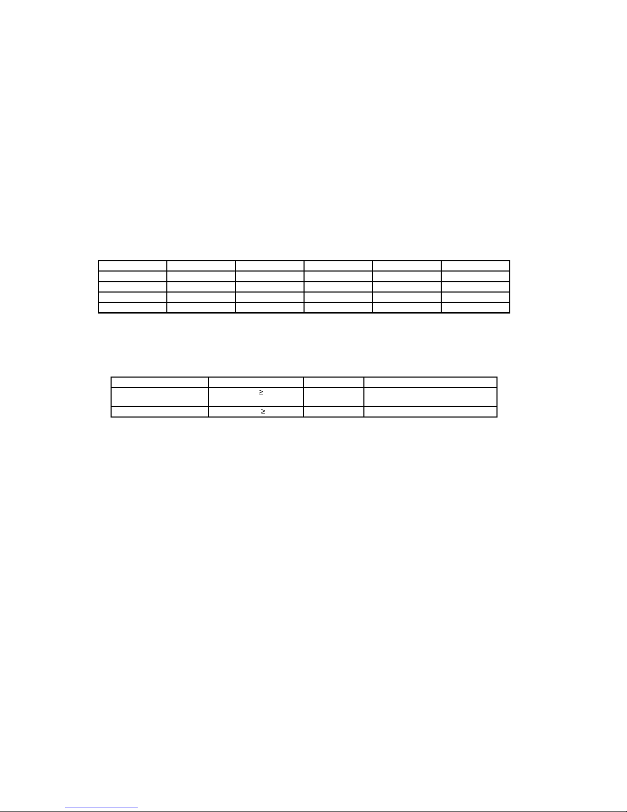
9.8.7. Sensor Disconnection Detection Control
• The sensor disconnection detection control activates when the following condition comply:
Sensor Detection Threshold Duration (Sec) Detection condition
Discharge Temperature < -4.5°C or 201.8°C 5 Other than compressor start control
and compressor ON
Outdoor heat exchange < -50.5°C or 103.7°C 5 Regularly
• During sensor disconnection, sensor error is displayed; all operations stops except outdoor fan remaining heat removal control.
9.8.8. Four-way Valve Error Detection Control
• The four-way valve error detection control starts when:
− During cooling operation, when indoor heat exchanger temperature exceeds 45°C in 5 minutes after compressor starts.
− During heating operation, when indoor heat exchanger temperature is below 5°C in 5 minutes after compressor starts.
• During four-way valve error, compressor is shut down and indoor unit is set to thermo-off status.
• After 3 occasions, four-way valve error is displayed; all operations stopped except outdoor fan remaining heat removal control.
9.8.9. Valve Error Detection Control
• This control is to protect the compressor.
• Valve error is detected if comply with condition below:
− Power is on for the first time and within 5 minutes from compressor starts (However, the unit is considered power on for first
time when compressor starts operating continuously for 7 minutes).
− Indoor heat exchanger temperature at compressor start -3°C < current heat exchanger temperature for 1 minute.
• During this error, four-way valve error is displayed; compressor is shutdown.
9.8.10. High-pressure Switch Disconnection Error Detection Control
• High-pressure switch disconnection is detected when high-pressure switch input continuously open for 1 minute while the
compressor shutdown.
• During this error, high-pressure switch error is displayed.
30
 Loading...