

Panasonic CS-E9CKP, CU-E9CKP5, CS-E12CKP, CU-E12CKP5, CS-E9CKP5 Service Manual
...
1 Features 2
2 Functions
3
3 Product Specifications
6
4 Dimensions
10
5 Refrigeration Cycle Diagram
12
6 Block Diagram
13
7 Wiring Diagram
14
8 Operation Details
16
9 Operating Instructions
41
© 2002 Matsushita Industrial Corp. Sdn. Bhd.
(11969-T). All rights reserved. Unauthorized copying
and distribution is a violation of law.
CS-E9CKP CU-E9CKP5
CS-E12CKP CU-E12CKP5
10 Installation And Servicing Air Conditioner Using R410A 46
11 Installation Instructions
57
12 Servicing Information
66
13 Technical Data
75
14 Exploded View
78
15 Replacement Parts List
79
16 Exploded View
80
17 Replacement Parts List
81
18 Electronic Circuit Diagram
82
Room Air Conditioner
CONTENTS
Page Page
Order No: MAC0210055C8
Panasonic ilmalämpöpumput korjaa ja huoltaa pääkaupunkiseudulla: Jäähdytinpalvelu RefGroup Oy
www.ilmalämpöpumput.com

•
Product
− Microcomputer-controlled compressor operating
frequency
− Vertical and Horizontal Airflow Directions
− Five modes of operation selection
− Power Mode operation
− Delay ON Timer and OFF Timer
− Standby operation
− Remote Controller with illuminable buttons
− Power Monitor Display LED
− Catechin Air Purifying Filter
− Triple Deodorizing Filter
− Ionizer Mode Operation
− Quiet Mode Operation
•
Serviceability
− Washable Front Panel
− Breakdown Self Diagnosis function
•
Environmental Protection
− Non-ozone depletion substances refrigerant (R410A)
•
Quality Improvement
− Gas leakage detection
− Deice operation
− Auto restart control
1 Features
2
CS-E9CKP CU-E9CKP5 / CS-E12CKP CU-E12CKP5
Panasonic ilmalämpöpumput korjaa ja huoltaa pääkaupunkiseudulla: Jäähdytinpalvelu RefGroup Oy
www.ilmalämpöpumput.com
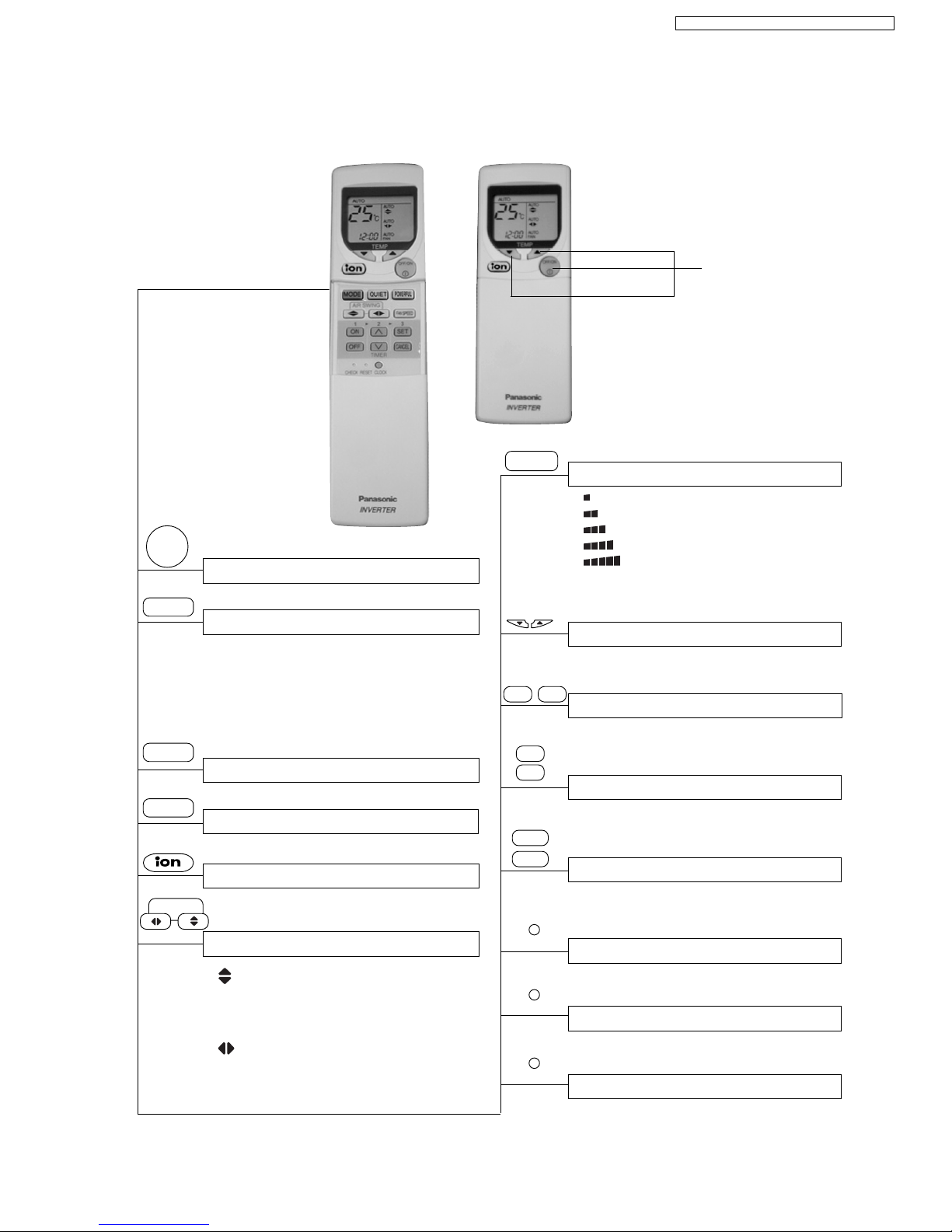
2 Functions
Remote Control
Operation OFF / ON
OFF/ON
I
Room Temperature Setting
TEMP
Operation Mode Selection
•
a
Automatic Operation
•
HEAT
Heating Operation
•
COOL
Cooling Operation
•
DRY
Soft Dry Operation
•
FAN
Fan Operation
Time / Timer Setting
• Hours and minutes setting.
Clock Setting
• Current time setting.
Quiet Mode Operation OFF / ON
QUIET
Airflow Direction Control
• 24-hour, OFF / ON Real Timer Setting.
Timer Operation Selection
Timer Operation Set / Cancel
• ON Timer and OFF Timer setting and
cancellation.
CLOCK
Powerful Mode Operation
POWERFUL
• Temperature Setting (16°C to 30°C)
Illuminable
buttons
• Vertical Automatic Airflow
Direction Control and Manual
Airflow Direction Control (5
stages of adjustment).
•
Horizontal Automatic Airflow
Direction Control and Manual
Airflow Direction Control (5
stages of adjustment).
Indoor Fan Speed Selection
FAN SPEED
• Low
•
Medium-
•
Medium
•
Medium+
•
High
•
AUTO
Automatic Fan Speed
FAN
Check Point
Reset Point
RESET
ON
TIMER
OFF
∧
∨
SET
CANCEL
CHECK
MODE
AIR SWING
• Breakdown self diagnosis function.
• Clear memory data.
Ion Mode Operation OFF / ON
3
CS-E9CKP CU-E9CKP5 / CS-E12CKP CU-E12CKP5
Panasonic ilmalämpöpumput korjaa ja huoltaa pääkaupunkiseudulla: Jäähdytinpalvelu RefGroup Oy
www.ilmalämpöpumput.com
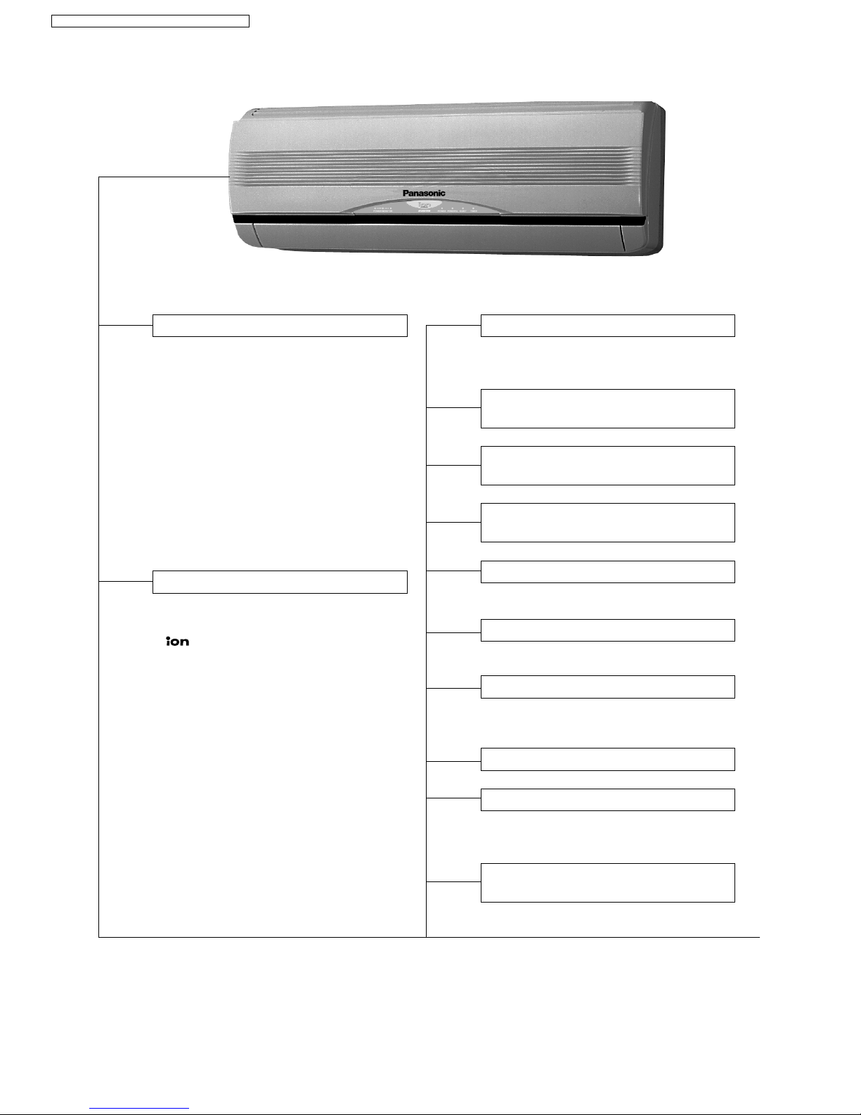
Indoor Unit
Automatic Operation Switch
• Press for < 5s to run Automatic Operation.
(Used when the remote control cannot be used.)
• Press continuously for 5s and < 8s to run
Forced Cooling Operation.
• Press continuously for 8s and < 11s to
run Forced Heating Operation.
• Press continuously for 11s and < 16s to
change different remote controlling
setting (A↔B Mode).
• Press continuously for 16s or < 21s to
switch OFF / ON Remote Control
Receiving Sound or H14 Abnormality
Detection Mode.
Operation Indication Lamps (LED)
Quiet Mode
Five Operation Modes
• Automatic, Heating, Cooling, Soft Dry
and Fan Operation.
Delay ON Timer and OFF Timer
Powerful Mode
• For quick cooling or heating.
•
POWER
(Green) ......
Lights up during
MONITOR
compressor operation.
• (Green) ............ Lights up in Ionizer
Mode Operation.
•
POWER
(Green) ...... Lights up in
operation, blinks in
Automatic Operation
Mode judging and Hot
Start operation.
•
TIMER
(Orange) .... Lights up in Timer
Setting.
Blinks in Self
Diagnosis Control.
•
QUIET
(Orange) .... Lights up in Quiet
Mode Operation.
•
POWERFUL
(Orange) ... Lights up when
Powerful Mode is
selected.
Automatic and 5 Manual Indoor
Fan Speeds
Automatic and 5 Manual Vertical
Airflow Directions
Automatic and 5 Manual Horizontal
Airflow Directions
Automatic Restart Control
• Operation is restarted after power failure
at previous setting mode.
Microcomputer-controlled Room
Temperature Control
• To provide extra quiet operation.
Ionizer Control
• Ionizer control for generate negative ion
in discharge air.
4
CS-E9CKP CU-E9CKP5 / CS-E12CKP CU-E12CKP5
Panasonic ilmalämpöpumput korjaa ja huoltaa pääkaupunkiseudulla: Jäähdytinpalvelu RefGroup Oy
www.ilmalämpöpumput.com
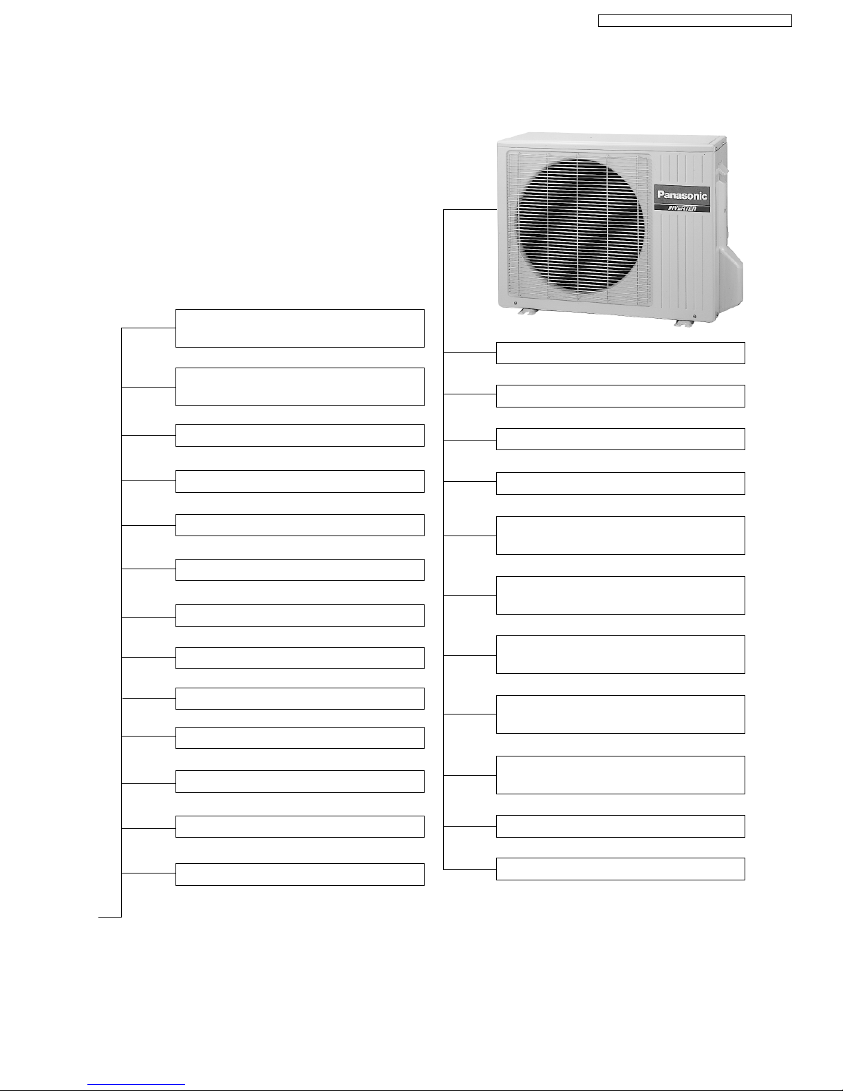
Deodorizing Control
Indoor Power Relay Control
Anti-Fog Discharge Control
Anti Freezing Control
Low Pressure Control
(Gas Leakeage Detection)
Breakdown Self Diagnosis
Function
Automatic Restart Control
Anti-Cold Draft Control
High Pressure Control
Hot Start
Intake Air Temperature Control
Standby Control
Deice Operation
Outdoor Unit
30 seconds Forced Operation
Time Delay Safety Control
High Pressure Control
Deice Operation
Standby Control
Compressor Overheating
Prevention Control
IPM (Power Transistor)
Overheating Protection Control
Total Running Current Control
Mininum Operation Frequency
Protection Control
**
**
* Details can be refered to OPERATION
DETAILS in this manual.
Low Operation Frequency
Protection Control
Outdoor Air Temperature
Control
5
CS-E9CKP CU-E9CKP5 / CS-E12CKP CU-E12CKP5
Panasonic ilmalämpöpumput korjaa ja huoltaa pääkaupunkiseudulla: Jäähdytinpalvelu RefGroup Oy
www.ilmalämpöpumput.com
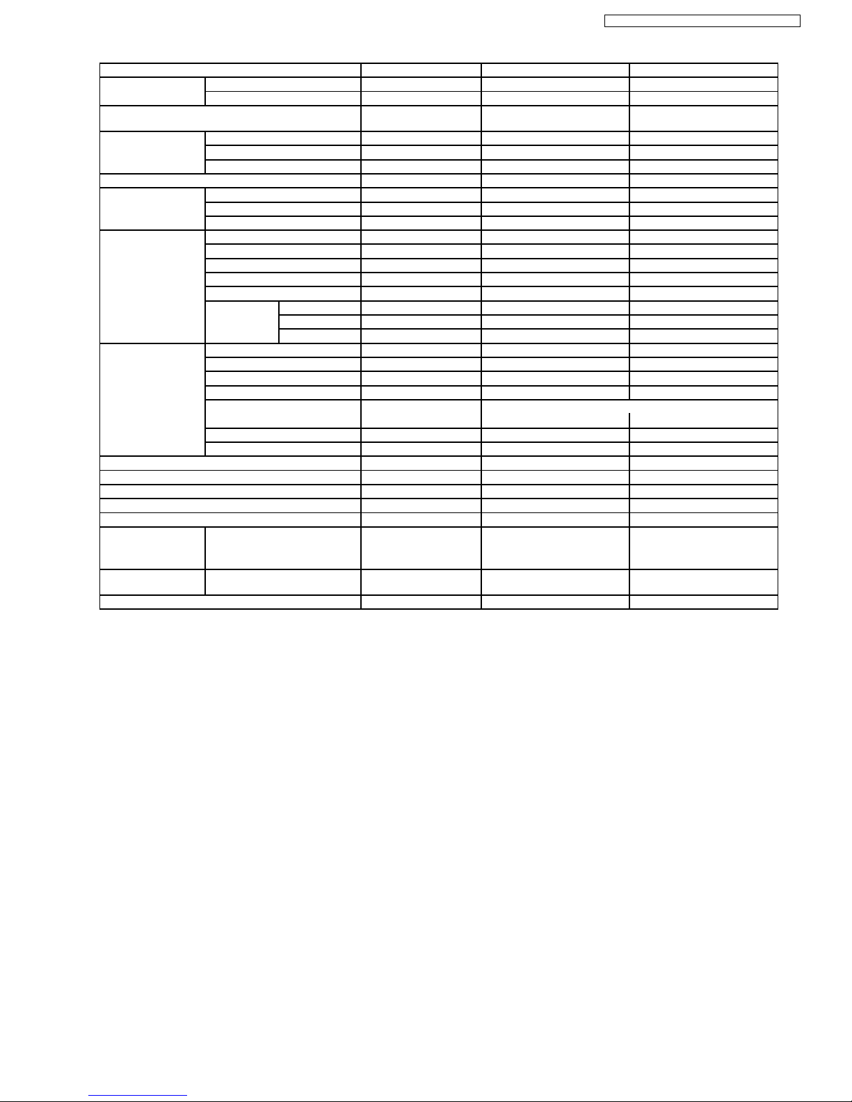
3 Product Specifications
Unit CS-E9CKP CU-E9CKP5
Cooling Capacity kW
kcal/h
BTU/h
2.6 (0.60 - 3.00)
2,240 (520 - 2,580)
8,870 (2,050 - 10,200)
Heating Capacity kW
kcal/h
BTU/h
3.6 (0.60 - 5.00)
3,100 (520 - 4,300)
12,300 (2,050 - 17,100)
Moisture Removal l/h
Pint/h
1.6
(3.4)
Power Source Phase
V
Cycle
Single
230
50
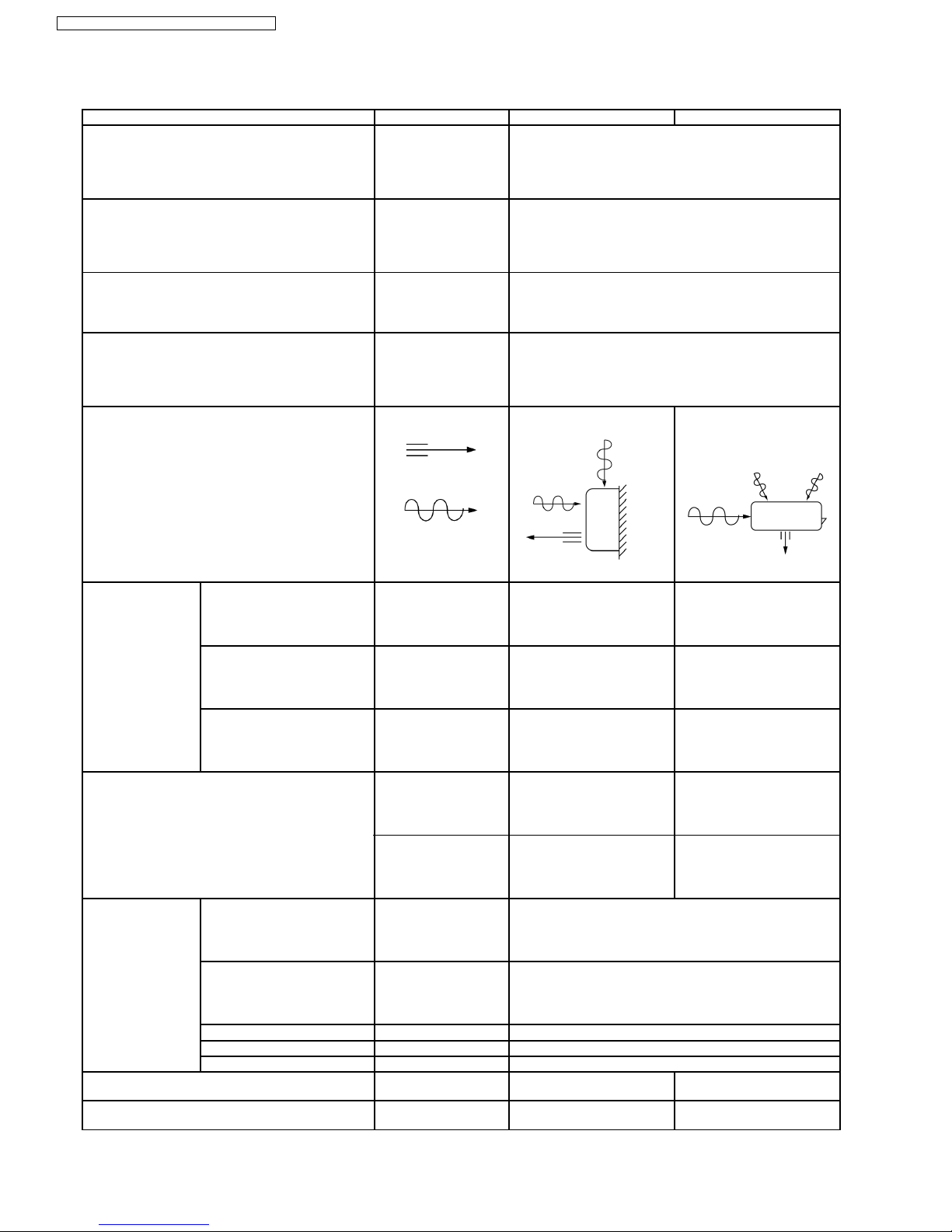
Airflow Method OUTLET
INTAKE
SIDE VIEW TOP VIEW
Air Volume Indoor Air (Lo) m3/min (cfm) Cooling; 6.5 (231) —
Heating; 7.1 (249)
Indoor Air (Me) m3/min (cfm) Cooling; 8.1 (286) —
Heating; 8.8 (312)
Indoor Air (Hi) m3/min (cfm) Cooling; 9.9 (350) Cooling; 30.0 (1,060)
Heating; 10.6 (370)
dB (A) Cooling; High 39, Low 26 Cooling; 46
Heating; High 40, Low 27 Heating; 47
Noise Level
Power level dB Cooling; High 50 Cooling; High 59
Heating; High 51 Heating; High 60
Electrical Data Input W Cooling; 700 (115 - 880)
Heating; 900 (110 - 1,400)
Running Current A Cooling; 3.3
Heating; 4.0
EER W/W (kcal/hw), BTU/hw Cooling; 3.71(3.20), 12.7
COP W/W (kcal/hw), BTU/hw Heating; 4.00 (3.44), 13.7
Starting Current A 4.00
Piping Connection Port
(Flare piping)
inch
inch
G ; Half Union 3/8”
L ; Half Union 1/4”
G ; 3-way valve 3/8”
L ; 2-way valve 1/4”
Pipe Size
(Flare piping)
inch
inch
G (gas side) ; 3/8”
L (liquid side) ; 1/4”
G (gas side) ; 3/8”
L (liquid side) ; 1/4”
6
CS-E9CKP CU-E9CKP5 / CS-E12CKP CU-E12CKP5
Panasonic ilmalämpöpumput korjaa ja huoltaa pääkaupunkiseudulla: Jäähdytinpalvelu RefGroup Oy
www.ilmalämpöpumput.com
Unit CS-E9CKP CU-E9CKP5
Drain
Hose
Inner diameter mm 12 —
Length m 0.65 —
Power Cord Length
Number of core-wire
2.1 m
3 core wires × 1.0 mm
2
—
—
Dimensions Height inch (mm) 10 - 26/32 (275) 21 - 9/32 (540)
Width inch (mm) 31 - 15/32 (799) 30 - 23/32 (780)
Depth inch (mm) 8 - 9/32 (210) 11 - 3/8 (289)
Net Weight lb (kg) 20 (9.0) 77 (35)
Compressor Type — Involute scroll
Motor Type — Brushless (4-pole)
Rated Output W — 700
Air Circulation Type Cross-flow Fan Propeller Fan
Material AS + Glass Fiber 20% P.P
Motor Type Transistor (8-poles) Induction (6-poles)
Input W — 61.3
Rate Output W 30 25
Fan Speed Lo (Cool/Heat) rpm 800 / 840 —
Me (Cool/Heat) rpm 1,000 / 1,040 —
Hi (Cool/Heat) rpm 1,200 / 1,270 770
Heat Exchanger Description Evaporator Condenser
Tube material Copper Copper
Fin material Aluminium (Pre Coat) Aluminium (Blue Coated)
Fin Type Slit Fin Corrugated Fin
Row / Stage (Plate fin configuration, forced draft)
2/15 1/20
FPI 21 19
Size (W × H × L) mm 610 × 315 × 25.4 732.1 × 508 × 22
Refrigerant Control Device — Capillary Tube
Refrigeration Oil (c.c) — RB68A (360)
Refrigerant (R410A) g (oz) — 840 (29.7)
Thermostat Electronic Control —
Protection Device Electronic Control Electronic Control
Length mm — C1, C2 ; 1,100, C3 ; 440
Capillary Tube Flow Rate l/min — C1, C2 ; 5.0, C3 ; 18.6
Inner Diameter mm — C1, C2 ; 1.2, C3 ; 1.7
Air Filter Material
Style
P.P.
Honeycomb
—
Fan Motor Capacitor µF, VAC — 1.8 µF, 400 VAC
•
Specifications are subject to change without notice for further improvement.
7
CS-E9CKP CU-E9CKP5 / CS-E12CKP CU-E12CKP5
Panasonic ilmalämpöpumput korjaa ja huoltaa pääkaupunkiseudulla: Jäähdytinpalvelu RefGroup Oy
www.ilmalämpöpumput.com
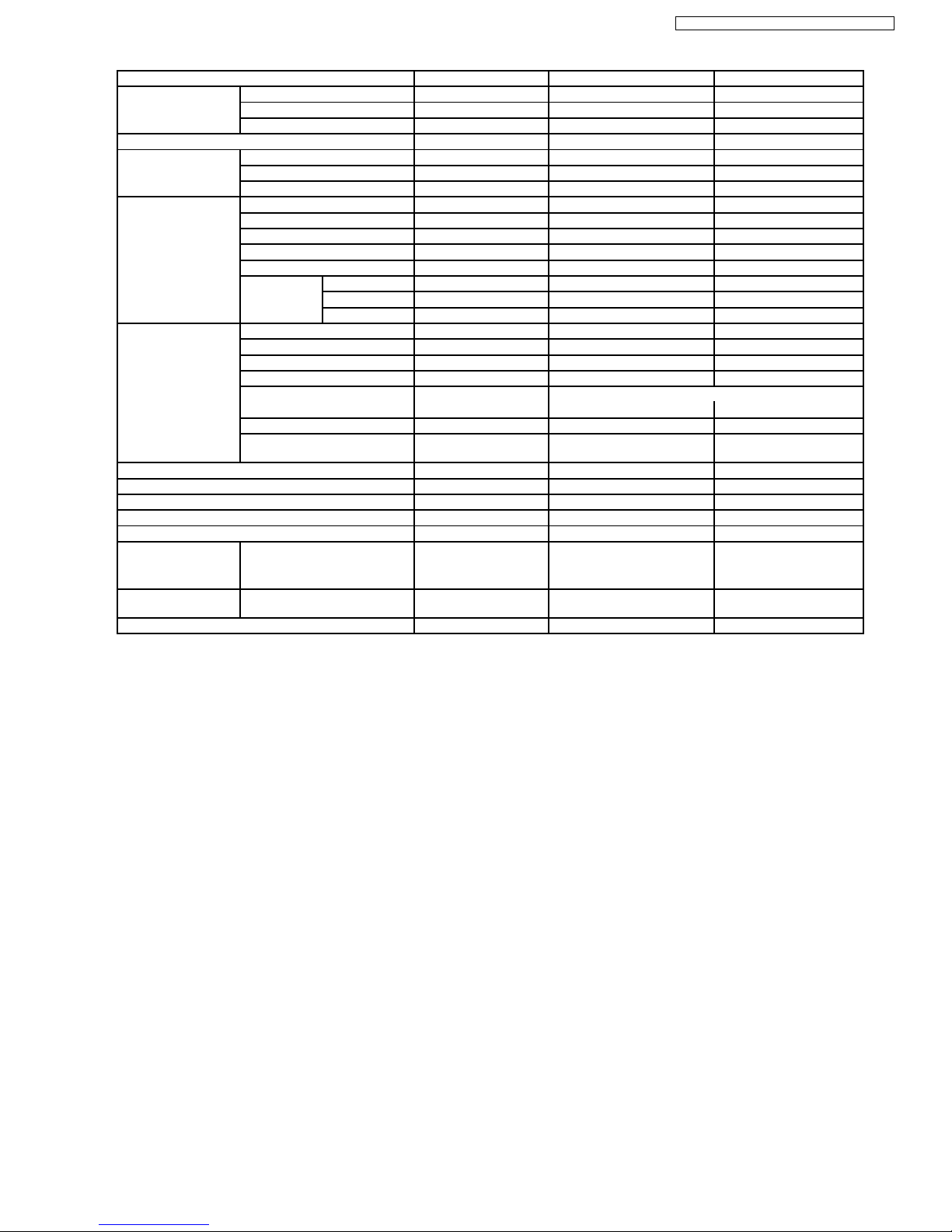
Unit CS-E12CKP CU-E12CKP5
Cooling Capacity kW
kcal/h
BTU/h
3.45 (0.60 - 4.00)
2,970 (520 - 3,440)
11,800 (2,050 - 13,600)
Heating Capacity kW
kcal/h
BTU/h
4.80 (0.60 - 6.50)
4,130 (520 - 5,590)
16,400 (2,050 - 22,200)
Moisture Removal l/h
Pint/h
2.0
(4.2)
Power Source Phase
V
Cycle
Single
230
50
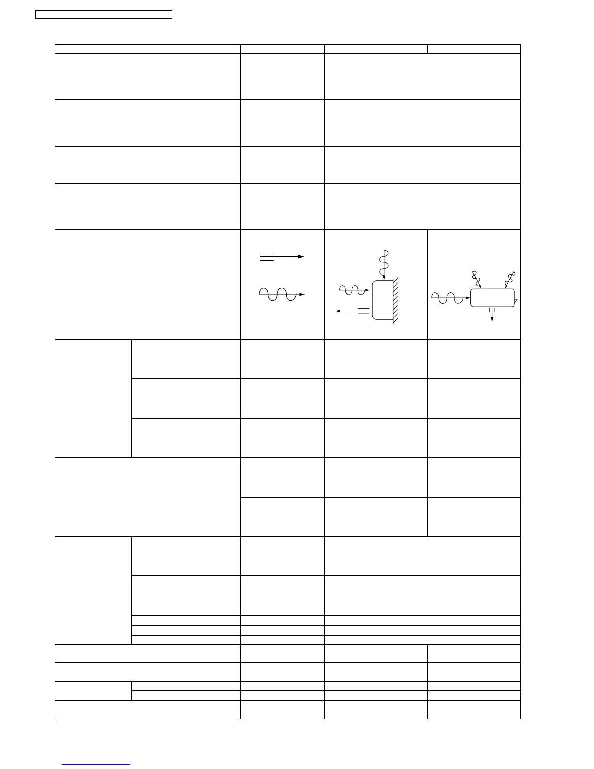
Airflow Method OUTLET
INTAKE
SIDE VIEW TOP VIEW
Air Volume Indoor Air (Lo) m3/min (cfm) Cooling; 7.3 (258) —
Heating; 9.2 (325)
Indoor Air (Me) m3/min (cfm) Cooling; 9.2 (323) —
Heating; 10.3 (360)
Indoor Air (Hi) m3/min (cfm) Cooling; 10.9 (380) Cooling; 31.0 (1,090)
Heating; 11.8 (420)
dB (A) Cooling; High 42, Low 29 Cooling; 48
Heating; High 42, Low 33 Heating; 50
Noise Level
Power level dB Cooling; High 53 Cooling; High 61
Heating; High 53 Heating; High 63
Electrical Data Input W Cooling; 950 (120 - 1,280)
Heating; 1,260 (115 - 1,890)
Running Current A Cooling; 4.4
Heating; 5.6
EER W/W (kcal/hw), BTU/hw Cooling; 3.63 (3.13), 12.4
COP W/W (kcal/hw), BTU/hw Heating; 3.81 (3.28), 13.0
Starting Current A 5.60
Piping Connection Port
(Flare piping)
inch
inch
G ; Half Union 1/2”
L ; Half Union 1/4”
G ; 3-way valve 1/2”
L ; 2-way valve 1/4”
Pipe Size
(Flare piping)
inch
inch
G (gas side) ; 1/2”
L (liquid side) ; 1/4”
G (gas side) ; 1/2”
L (liquid side) ; 1/4”
Drain
Hose
Inner diameter mm 12 —
Length m 0.65 —
Power Cord Length
Number of core-wire
2.1 m
3 core wires × 1.5 mm
2
—
—
8
CS-E9CKP CU-E9CKP5 / CS-E12CKP CU-E12CKP5
Panasonic ilmalämpöpumput korjaa ja huoltaa pääkaupunkiseudulla: Jäähdytinpalvelu RefGroup Oy
www.ilmalämpöpumput.com
Unit CS-E12CKP CU-E12CKP5
Dimensions Height inch (mm) 10 - 26/32 (275) 21 - 9/32 (540)
Width inch (mm) 31 - 15/32 (799) 30 - 23/32 (780)
Depth inch (mm) 8 - 9/32 (210) 11 - 3/8 (289)
Net Weight lb (kg) 20 (9.0) 82 (37)
Compressor Type — Involute scroll
Motor Type — Brushless (4-pole)
Rated Output W — 700
Air Circulation Type Cross-flow Fan Propeller Fan
Material AS + Glass Fiber 20% P.P
Motor Type Transistor (8-poles) Induction (6-poles)
Input W — 65.9
Rate Output W 30 29
Fan Speed Lo (Cool/Heat) rpm 880 / 1,100 —
Me (Cool/Heat) rpm 1,100 / 1,230 —
Hi (Cool/Heat) rpm 1,310 / 1,410 830
Heat Exchanger Description Evaporator Condenser
Tube material Copper Copper
Fin material Aluminium (Pre Coat) Aluminium (Blue Coated)
Fin Type Slit Fin Corrugated Fin
Row / Stage (Plate fin configuration, forced draft)
2/15 2/24
FPI 21 17
Size (W × H × L) mm 610 × 315 × 25.4 703.8
735.0
× 504 × 36.4
Refrigerant Control Device — Capillary Tube
Refrigeration Oil (c.c) — RB68A (360)
Refrigerant (R410A) g (oz) — 1,020 (36.0)
Thermostat Electronic Control —
Protection Device Electronic Control Electronic Control
Length mm — C1, C2 ; 1,100, C3 ; 750
Capillary Tube Flow Rate l/min — C1, C2 ; 5.0, C3 ; 15.4
Inner Diameter mm — C1, C2 ; 1.2, C3 ; 1.7
Air Filter Material
Style
P.P.
Honeycomb
—
Fan Motor Capacitor µF, VAC — 2.0 µF, 400 VAC
•
Specifications are subject to change without notice for further improvement.
9
CS-E9CKP CU-E9CKP5 / CS-E12CKP CU-E12CKP5
Panasonic ilmalämpöpumput korjaa ja huoltaa pääkaupunkiseudulla: Jäähdytinpalvelu RefGroup Oy
www.ilmalämpöpumput.com
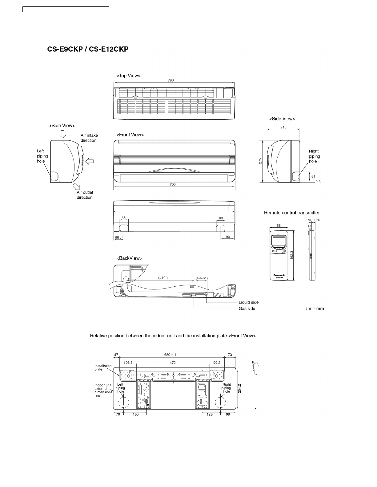
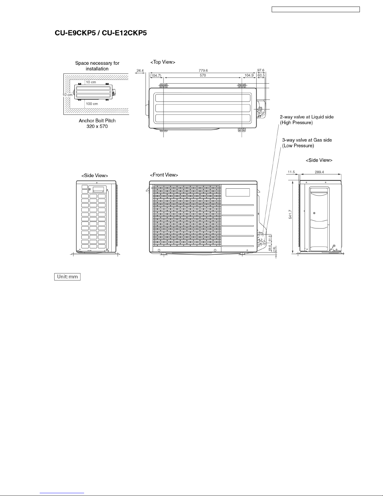
4 Dimensions
10
CS-E9CKP CU-E9CKP5 / CS-E12CKP CU-E12CKP5
Panasonic ilmalämpöpumput korjaa ja huoltaa pääkaupunkiseudulla: Jäähdytinpalvelu RefGroup Oy
www.ilmalämpöpumput.com
11
CS-E9CKP CU-E9CKP5 / CS-E12CKP CU-E12CKP5
Panasonic ilmalämpöpumput korjaa ja huoltaa pääkaupunkiseudulla: Jäähdytinpalvelu RefGroup Oy
www.ilmalämpöpumput.com
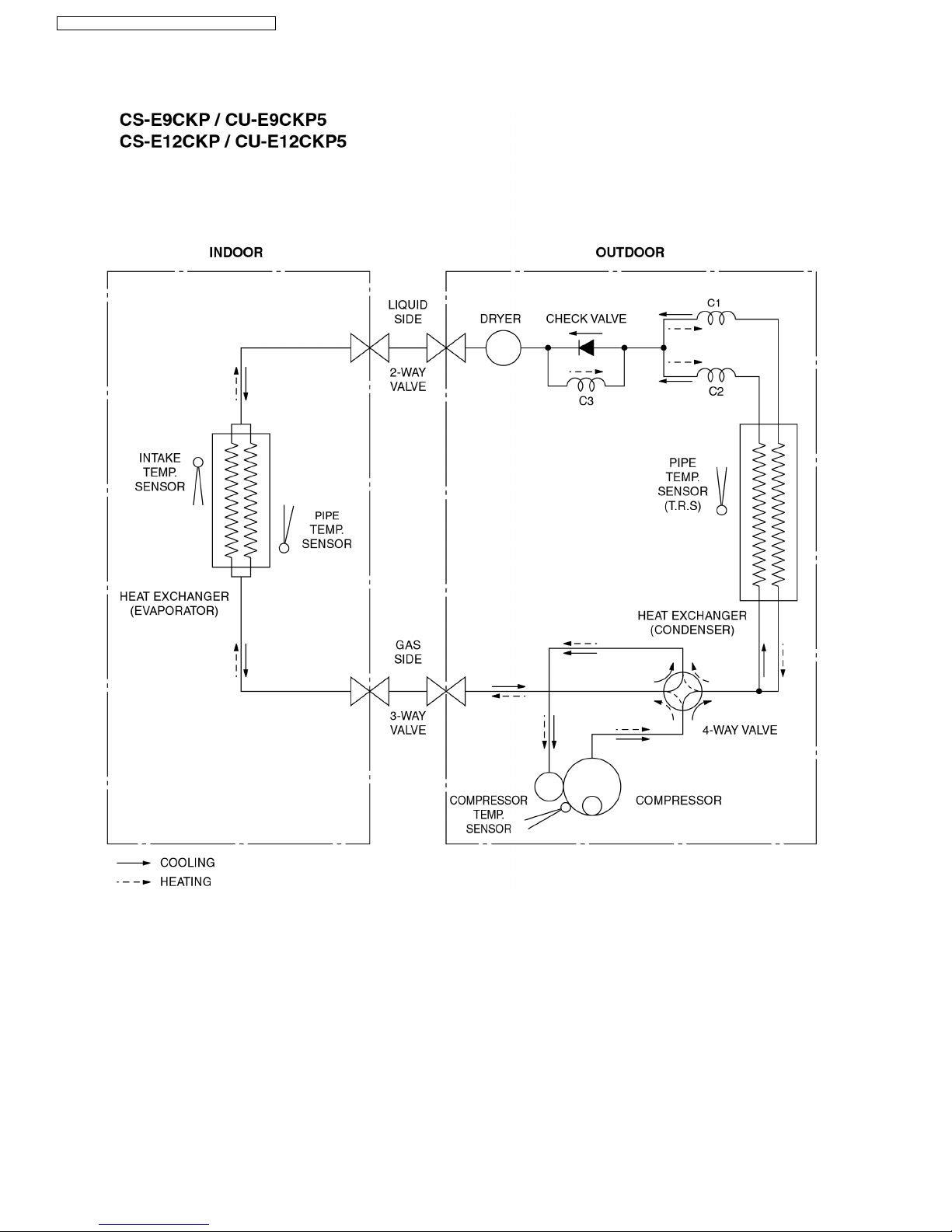
5 Refrigeration Cycle Diagram
12
CS-E9CKP CU-E9CKP5 / CS-E12CKP CU-E12CKP5
Panasonic ilmalämpöpumput korjaa ja huoltaa pääkaupunkiseudulla: Jäähdytinpalvelu RefGroup Oy
www.ilmalämpöpumput.com
6 Block Diagram
13
CS-E9CKP CU-E9CKP5 / CS-E12CKP CU-E12CKP5
Panasonic ilmalämpöpumput korjaa ja huoltaa pääkaupunkiseudulla: Jäähdytinpalvelu RefGroup Oy
www.ilmalämpöpumput.com
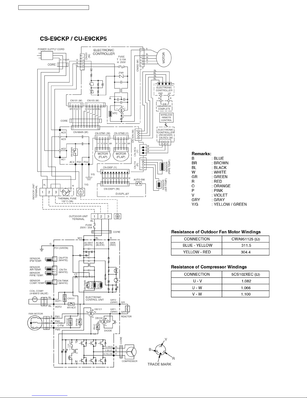
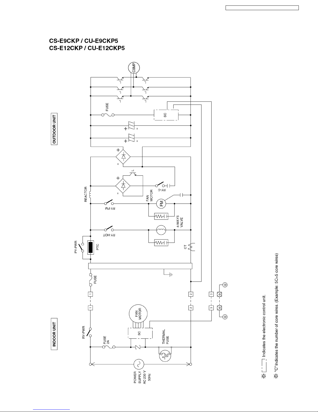
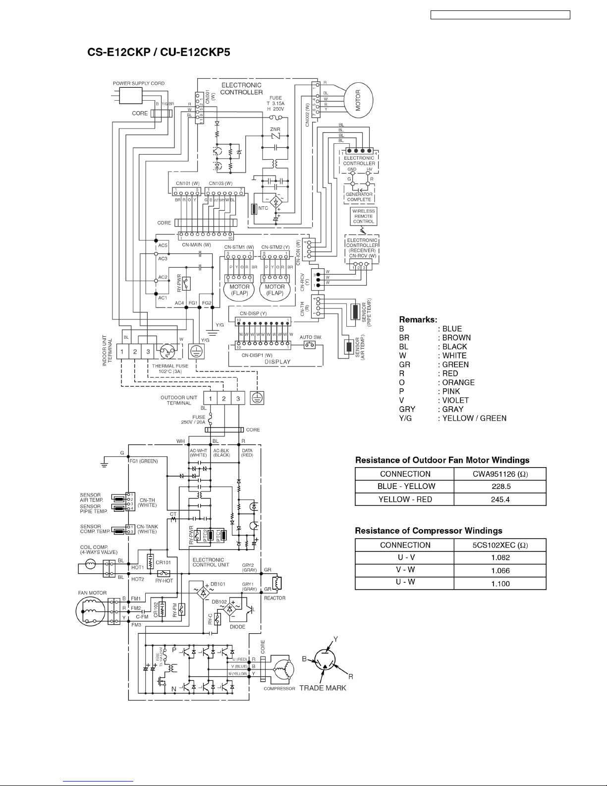
7 Wiring Diagram
14
CS-E9CKP CU-E9CKP5 / CS-E12CKP CU-E12CKP5
Panasonic ilmalämpöpumput korjaa ja huoltaa pääkaupunkiseudulla: Jäähdytinpalvelu RefGroup Oy
www.ilmalämpöpumput.com
15
CS-E9CKP CU-E9CKP5 / CS-E12CKP CU-E12CKP5
Panasonic ilmalämpöpumput korjaa ja huoltaa pääkaupunkiseudulla: Jäähdytinpalvelu RefGroup Oy
www.ilmalämpöpumput.com
8.1. BASIC FUNCTION
8 Operation Details
Inverter control, which equipped with a microcomputer in determining the most suitable operating mode as time passes,
automatically adjust output power for maximum comfort always. In order to achieve the suitable operating mode, the
microcomputer maintains the set temperature by measuring the temperature of the environment and performing temperature
shifting. The compressor at outdoor unit is operating following the frequency instructed by the microcomputer at indoor unit that
judging the conditio n according to internal setting temperature and intake air temperature.
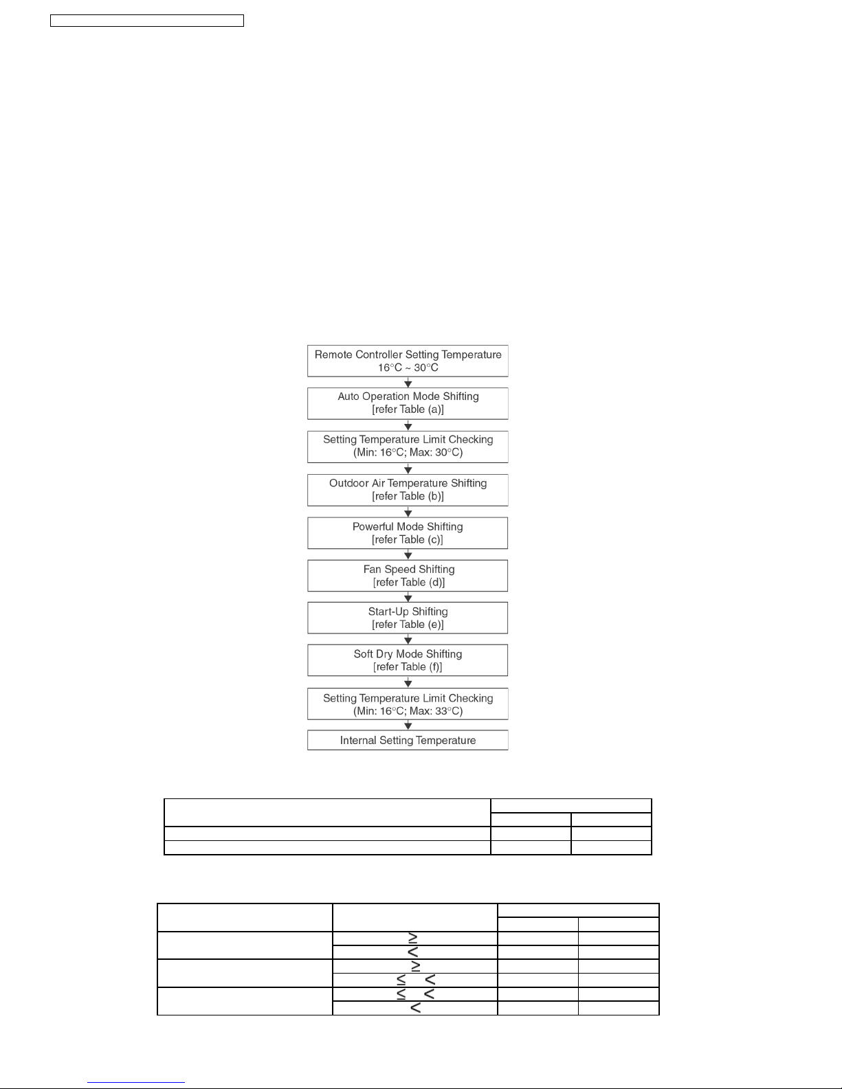
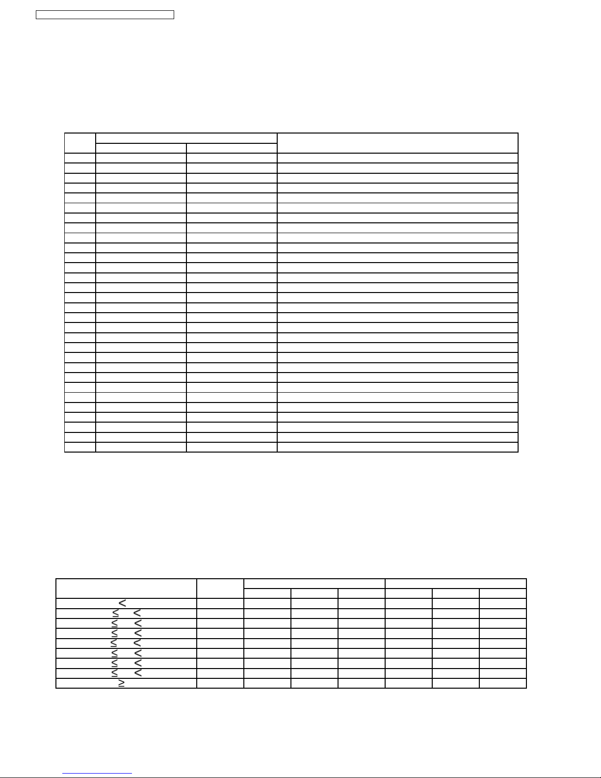
8.1.1. Internal Setting Temperature
Once the operation starts, remote controller setting temperature will be taken as base value for temperature shifting processes.
These shifting processes are depend ing on the air conditioner settings and the operation environment. The final shifted value
will be used as internal setting temperature and it is updated continuously whenever the electrical power is supplie d to the unit.
Table (a): Auto Operation Mode Setting
Mode Shift: Temperature Shift (°C)
E9CKP E12CKP
Cooling/Soft Dry→Heating -2.0 -2.0
Heating→Cooling/Soft Dry +2.0 +2.0
Table (b): Outdoor Air Temperature Shifting
Mode: Outdoor Temperature, X (°C): Temperature Shift (°C)
E9CKP E12CKP
Cooling/Soft Dry X 30 0.0 0.0
X 30 +0.5 +0.5
Heating X 9 0.0 0.0
5 X 9 +0.5 +1.0
1 X 5 +1.0 +1.5
X 1 +1.5 +2.0
16
CS-E9CKP CU-E9CKP5 / CS-E12CKP CU-E12CKP5
Panasonic ilmalämpöpumput korjaa ja huoltaa pääkaupunkiseudulla: Jäähdytinpalvelu RefGroup Oy
www.ilmalämpöpumput.com
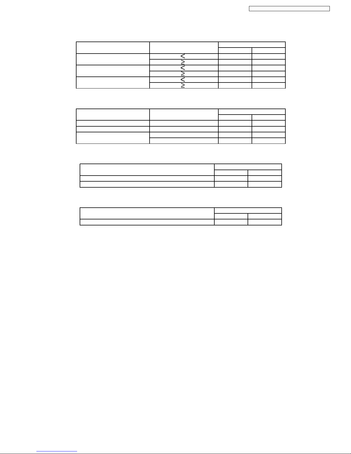
Table (c): Powerful Mode Shifting
Mode: Period, X (min): Temperature Shift (°C)
E9CKP E12CKP
Cooling X 20 -2.0 -2.0
X 20 0.0 0.0
Soft Dry X 20 -1.0 -1.0
X 20 0.0 0.0
Heating X 20 +3.5 +3.5
X 20 +3.5 +3.5
Table (d): Fan Speed Shifting
Mode: Fan Speed: Temperature Shift (°C)
E9CKP E12CKP
Cooling All +1.5 +1.5
Soft Dry All +1.0 +1.0
Heating Lo +1.0 +1.0
Me-, Me, Me+, Hi, Auto +0.5 +0.5
Table (e): Start-Up Shifting
Mode within 60 Minutes from Start-up: Temperature Shift (°C)
E9CKP E12CKP
Cooling/Soft Dry -1.0 -1.0
Heating +2.0 +2.0
Table (f): Soft Dry Mode Shifting
Mode: Temperature Shift (°C)
E9CKP E12CKP
Soft Dry +1.0 +1.0
17
CS-E9CKP CU-E9CKP5 / CS-E12CKP CU-E12CKP5
Panasonic ilmalämpöpumput korjaa ja huoltaa pääkaupunkiseudulla: Jäähdytinpalvelu RefGroup Oy
www.ilmalämpöpumput.com
8.1.2. Frequency Instruction for Compressor Operation
Operation of compressor is based on instructed frequency, continuously from indoor unit´s microcomputer after performing
temperature sampling and judgment.
There are total 30 differen t frequency values, which listed as Table on Frequency Number, to be instructed based on the
temperature judgment
Table on Frequency Number
No. Frequency (Hz) Remarks
E9CKP E12CKP
1 12.0 12.0 Freq. MIN
2 15.0 15.0
3 18.0 18.0
4 21.0 21.0
5 23.0 23.0
6 25.0 25.0
7 26.0 28.0
8 30.0 32.0
9 33.0 36.0
10 35.0 40.0
11 36.0 44.0
12 38.0 48.0
13 39.0 52.0 Fc
14 40.0 57.0
15 47.0 62.0 Fc max. (E9CKP)
16 49.0 67.0 Fc max. (E12CKP)
17 56.0 68.5 Fh
18 58.0 72.0
19 63.0 76.0
20 66.0 80.0
21 70.0 85.0
22 73.0 88.0
23 77.0 91.0
24 80.0 94.0
25 83.0 98.0
26 86.0 102.0
27 87.0 104.0
28 88.0 106.0
29 89.0 108.0
30 90.0 110.0 Fh max.
For normal start of operation, including Thermo-OFF, Deice-Resuming, and remote controller ON-OFF starts, the compressor
starts to operate at frequency no. 8, values of 30Hz and 32Hz for E9CKP and E12CKP respectively, for 60 seconds.
The frequency to be judged and instructed, however, starts to judge once the air conditioner operated and the judgment will
continue every 30 seconds until it is stopped by all kinds of compressor off conditions. This judgment is based on the internal
temperature sampling that involving internal setting temperature and intake air temperature.
From the internal sampling, the temperature differen t (intake air temperature - internal setting temperature) will be used to judge
the Zone on which the frequency to be instructed for the initial operation of compressor (refer to Table on Initial Frequency Zone).
Table on Initial Frequency Zone
Temperature, X (°C) Zone Freq. No. - E9CKP Freq. No. - E12CKP
(Intake Air - Internal Setting) Cooling Soft Dry Heating Cooling Soft Dry Heating
X -2.5 0 1 4 30 1 4 30
-2.5 X -1.5 1 1 4 30 1 4 30
-1.5 X -1.0 2 1 4 10 1 4 10
-1.0 X -0.5 3 1 4 7 1 4 7
-0.5 X +1.0 4 4 4 4 4 4 4
+0.5 X +1.0 5 6 6 1 6 6 1
+1.0 X +1.5 6 9 7 1 9 8 1
+1.5 X +2.5 7 15 7 1 16 8 1
X +2.5 8 15 7 1 16 8 1
After the initial operation, the instructed frequency will change or shift from initial frequency according to the judgment on
temperature differen t from sampling (refer to the Table on Shifting Frequency Zone).
18
CS-E9CKP CU-E9CKP5 / CS-E12CKP CU-E12CKP5
Panasonic ilmalämpöpumput korjaa ja huoltaa pääkaupunkiseudulla: Jäähdytinpalvelu RefGroup Oy
www.ilmalämpöpumput.com
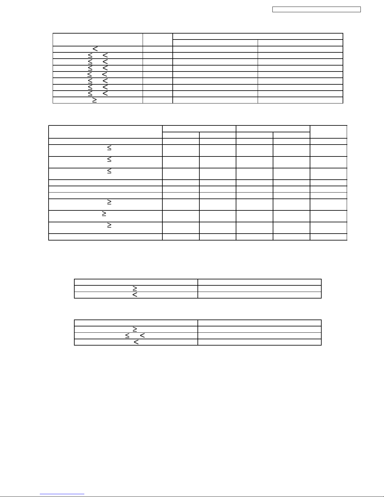
Table on Shifting Frequency Zone
Temperature, X (°C) Zone Frequency No. Shifting:
(Intake Air - Internal Setting) Cooling Mode / Soft Dry Mode Heating Mode
X -2.5 0 Shift to Freq. MIN Shift to Freq. MAX
-2.5 X -1.5 1 Shift to Freq. MIN Shift to Freq. MAX
-1.5 X -1.0 2 -2 Freq. No. +2 Freq. No.
-1.0 X -0.5 3 -1 Freq. No. +1 Freq. No.
-0.5 X +1.0 4 Same Freq. No. Same Freq. No.
+0.5 X +1.0 5 +1 Freq. No. -1 Freq. No.
+1.0 X +1.5 6 +2 Freq. No. -2 Freq. No.
+1.5 X +2.5 7 Shift to Freq. MAX Shift to Freq. MIN
X +2.5 8 Shift to Freq. MAX Shift to Freq. MIN
Besides, the range of operation frequency will change according to the setting environment as listed below:
Condition: Freq. no. for E9CKP Freq. no. for E12CKP Remarks
MIN MAX MIN MAX
Cooling Mode 1 15 1 16 (a)
- if remote controller set 28°C & fan speed =
Hi
7 15 7 16 (a), (c)
- if remote controller set 28°C & fan speed =
Me-, Me, Me+, Auto
5 15 6 16 (a), (c)
- if remote controller set 28°C & fan speed =
Lo
4 15 5 16 (a), (c)
- if Powerful Mode ON 7 15 7 16 (a), (c)
Soft Dry Mode 4 7 4 8
Heating Mode 1 30 1 30 (b)
- if remote controller set 18°C & fan speed =
Hi
10 30 10 30 (b), (d)
- if remote control set 18°C & fan speed =
Me-, Me, Me+, Auto
9 30 9 30 (b), (d)
- if remote controller set 18°C & fan speed =
Lo
8 30 8 30 (b), (d)
- if Powerful Mode ON 10 30 10 30 (b), (d)
Remark:
(a) If frequency decreases from MAX, the following frequency performed will be depending to outdoor temperature, as given in below table
(for 30 seconds only) and then continues as normal rule.
Outdoor Temperature , X (°C) Frequency No.
X 30 13
X 30 7
(b) (If frequency increases from Freq. No. 17, the following frequency performed is as below (for 30 seconds only) and then continue as
normal rule.
Outdoor Temperature , X (°C) Frequency No.
X 10 10
X X 10 13
X 4 17
(c) When temperature different (intake - setting) < -1.0 °C or Thermo-Off activated and only valid for 120 seconds; not applicable during Soft
Dry Mode, and Anti-freezing control.
(d) When temperature different (intake - setting) > +1.5 °C or Thermo-Off activated and only valid for 130 seconds.
19
CS-E9CKP CU-E9CKP5 / CS-E12CKP CU-E12CKP5
Panasonic ilmalämpöpumput korjaa ja huoltaa pääkaupunkiseudulla: Jäähdytinpalvelu RefGroup Oy
www.ilmalämpöpumput.com
The frequency judgment will perform every 30 seconds. Nevertheless, the frequency is instructed to outdoor compressor after
every 90 seconds except when either one of the below conditions is met:
(a) The frequency judged changes from frequency number decreasing zones (Zone No. 0 or 1 or 2 or 3) to frequency number
increasing zones (Zone No. 5 or 6 or 7 or 8) and vice verse.
(b) The frequency judged falls on frequency shifting zone number 0 or 1 (shift to Frequency MIN) at Cooling mode operation.
(c) The frequency judged falls on frequency shifting zone number 4 (no shifting in frequency number) at Cooling mode
operation.
(d) The frequency judged falls on frequency shifting zone number 7 or 8 (shift to Frequency MAX) at automatic fan speed.
The instructed frequency is the value referred by the frequency number, which resulted from previous instructed frequency
number with the numbers of frequency numbers to be shifted, in Table on Frequency Number.
Time (s) 0 30 60 90 120 150 180 210 240 270 300 330
Zone (+/-) + + + + + +/- + - - +/- +
Freq. zone based on temp. diff. 8 7 7 6 6 6 4 5 3 1 4 5
Frequency shift Max Max +2 +2 +2 0 +1 -1 Min 0 +1
Freq. no. judged based on
previous
15 30 30 17 17 17 15 16 14 5 4 6
Freq. instruction (Y/N) & its
condition
Y (a) Y (a) Y (b) N N Y (c) Y (d) N Y (e) Y (f) Y (d) N
Freq. control condition (g) (g) (h) (h) (i)
Instructed freq. 8 8 15 15 15 14 5 5 5
Operation freq. 8 8 15 15 15 15 15 15 14 5 5 5
Note:
(a) Starting frequency.
(b) Frequency judged falls on Zone 7 or 8 (shift to Frequency MAX).
(c) 90 seconds frequency instruction limit.
(d) Frequency judged falls on Zone 4 (no shifting).
(e) Frequency no. changes from no. increasing zones to no. decreasing zones.
(f) Frequency judged falls on Zone 0 or 1 (shift to Frequency MIN).
(g) Normal initial operation starts (60 s).
(h) Maximum frequency for normal cooling operation
(i) Minimum frequency for normal cooling operation.
20
CS-E9CKP CU-E9CKP5 / CS-E12CKP CU-E12CKP5
Panasonic ilmalämpöpumput korjaa ja huoltaa pääkaupunkiseudulla: Jäähdytinpalvelu RefGroup Oy
www.ilmalämpöpumput.com
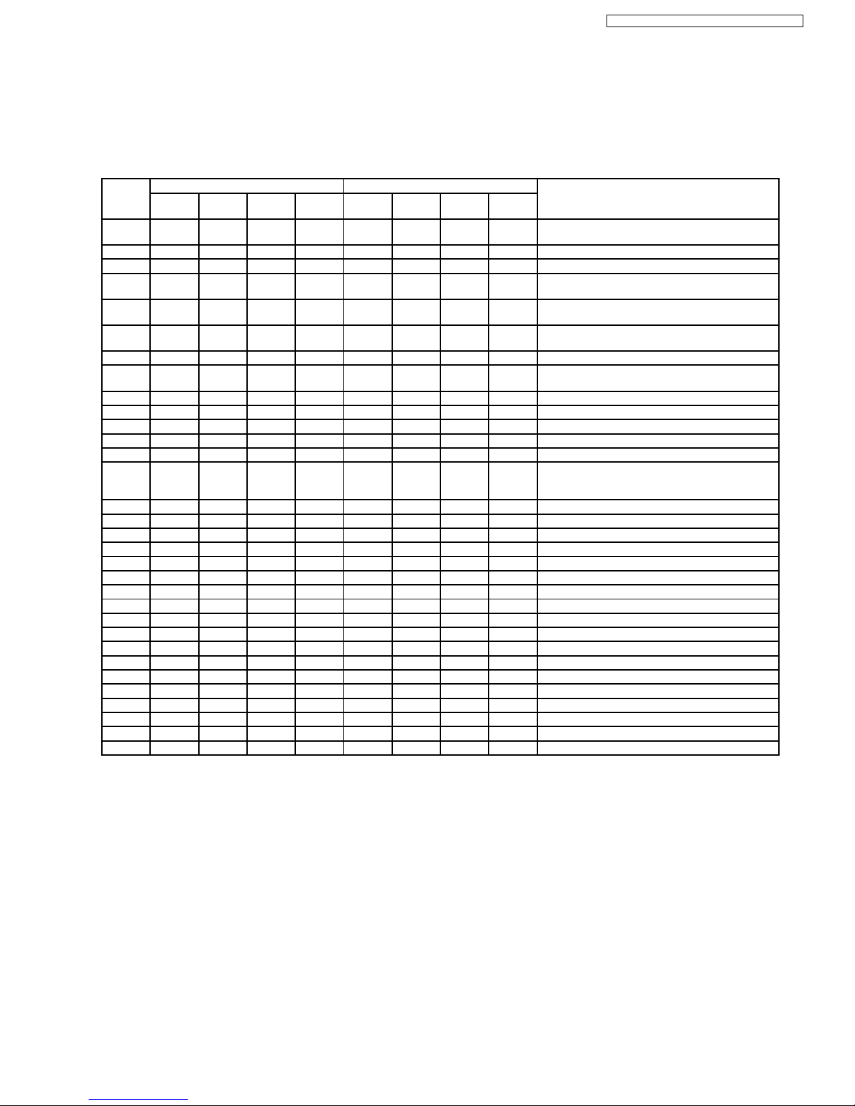
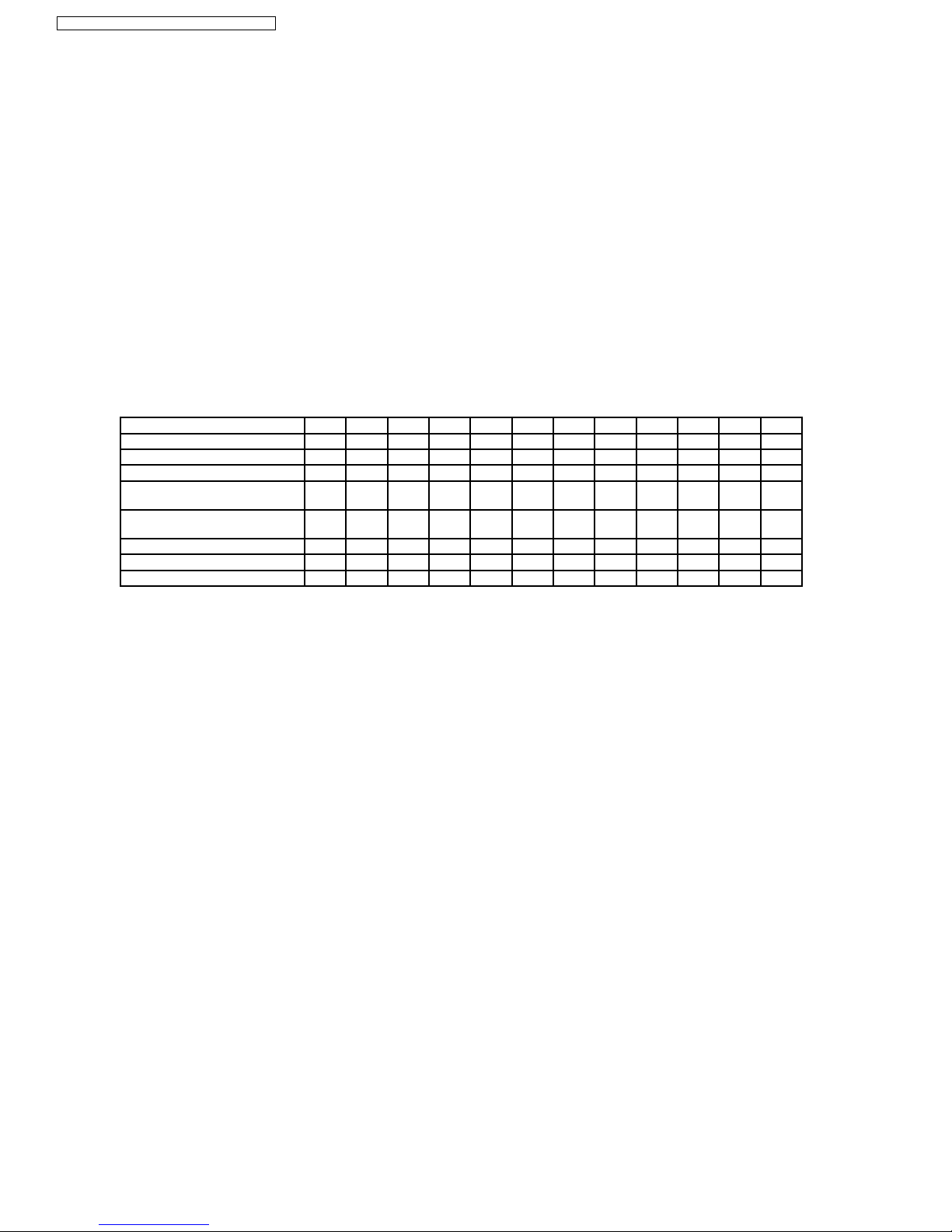
8.1.3. Indoor Fan Motor Operation
There are 31 fan speed numbers assigned for different fan speed operation at designed conditions, as shown in below table. The
fan speed can be set manually using remote control (5 speeds for cooling mode: Lo, Me-, Me, Me+, Hi; 5 speeds for heating: Lo,
Me-, Me, Me+, Shi) or let it automatically changes depend ing on the operation and its environment.
Fan
Speed
No.
CS-E9CKP CS-E12CKP Remark
Voltage
(V)
Cooling Dry Heating Voltage
(v)
Cooling Dry Heating
0 OFF OFF OFF OFF OFF OFF - Hot start control.
- Deice control.
1
2 3.03 3.03
3 3.05 SLo 3.05 SLo - Soft Dry operation mode.
- ON timer pre-operation (D).
4 3.13 3.13 - Auto operation mode judgment (C/D).
- ON timer preparation sampling (C/D).
5 3.15 3.23 - Auto operation mode judgment (H).
- ON timer preparation sampling (H).
6 3.16 Lo 3.29 Lo - ON timer pre-operation at Auto fan (C).
7 3.23 Lo 3.34 - ON timer pre-operation at Auto fan for E9CKP
(H).
8 3.24 3.40
9 3.31 Me- 3.44 Me-
10 3.36 3.53
11 3.39 Me- 3.60 Me - Powerful Mode at Lo fan for E12CKP (C).
12 3.44 3.63
13 3.47 Me 3.66 Lo - Powerful Mode at Lo fan for E9CKP (C).
- ON timer pre-operation at Auto fan for E12CKP
(H).
14 3.55 Me 3.68 - Powerful Mode at Lo fan for E9CKP (H).
15 3.57 3.71
16 3.60 3.75 Me17 3.63 Me+ 3.77 Me+ - Powerful Mode at Me- fan (C).
18 3.66 3.83
19 3.68 3.85
20 3.71 3.86 Me - Powerful Mode at Lo fan for E12CKP (H).
21 3.73 Me+ 3.91 - Powerful Mode at Me- fan for E9CKP (H).
22 3.77 3.94
23 3.79 3.98 Me+ - Powerful Mode at Me- fan for E12CKP (H).
24 3.80 4.00
25 3.82 Hi 4.00 Hi - Powerful mode at Me, Me+ or Hi fan (C).
26 3.85 4.01
27 3.89 4.05 SHi
28 3.90 SHi 4.08
29 3.91 4.11
30 3.93 SHi 4.16 SHi - Powerful mode at Me, Me+ or Hi fan (H).
31 4.07 4.30
21
CS-E9CKP CU-E9CKP5 / CS-E12CKP CU-E12CKP5
Panasonic ilmalämpöpumput korjaa ja huoltaa pääkaupunkiseudulla: Jäähdytinpalvelu RefGroup Oy
www.ilmalämpöpumput.com
8.1.4. Cooling Mode Automatic Indoor Fan Speed
The automatic fan speed for cooling operation is as shown in below patterns (a → b → c →→h) with each pattern 10 seconds.
The fan speed for each level (X or Y or Z) is as below table.
Model No. E9CKP E12CKP
Level X Y Z X Y Z
Normal Operation Fan Speed No. 11 9 7 10 9 7
Powerful Mode Fan Speed No. 13 11 9 12 10 9
(a) During cooling operation, if all the following conditions occur, indoor fan speed will be shifted to Shi internally.
(i) Indoor intake air temperature
24°C.
(ii) Instructed frequency = 39 Hz (E9CKP ) or 52 Hz (E12CKP).
(iii) Remote controller setting temperature = 16°C.
(iv) Remote controller setting fan speed = Hi.
(v) Outdoor air temperature
30°C.
(vi) Operation starts
30 minutes.
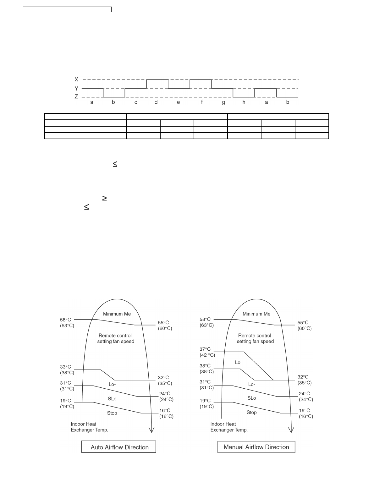
8.1.5. Heating Mode Indoor Fan Motor Operation (Anti Cold draft Control)
Indoor fan speed varies in accordance to indoor heat exchanger temperature, based on type of air volume and direction, as shown
below.
1. Manual Fan Speed
22
CS-E9CKP CU-E9CKP5 / CS-E12CKP CU-E12CKP5
Panasonic ilmalämpöpumput korjaa ja huoltaa pääkaupunkiseudulla: Jäähdytinpalvelu RefGroup Oy
www.ilmalämpöpumput.com
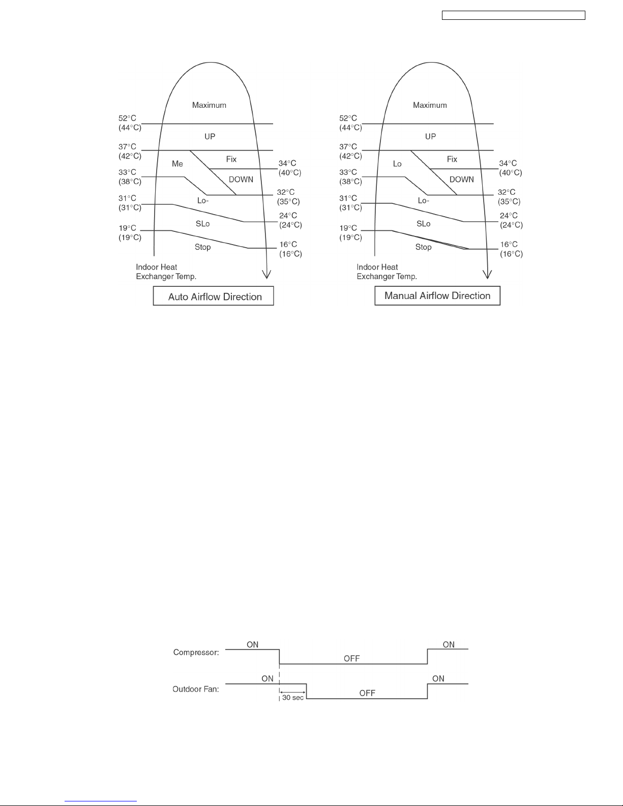
2. Auto Fan Speed
Note:
a. UP:
• If move from Lo or Lo-, the fan speed will be shifted to Maximum.
• If move from Maximum, the fan speed no change.
• Other than that, the fan speed will be increased one Fan Speed No.
b. DOWN:
• The fan speed will be decreased one Fan Speed No.
c. Fix:
• No change in fan speed.
d. Maximum:
• Fan speed will be increased to maximum auto fan speed.
e. Temperature in ( ) is for Powerful Mode operation.
8.1.6. Outdoor Fan Motor Operation
Outdoor fan motor is operated with one fan speed only. It starts when compressor starts operation and it stops 30 seconds after
compressor stops operation.
23
CS-E9CKP CU-E9CKP5 / CS-E12CKP CU-E12CKP5
Panasonic ilmalämpöpumput korjaa ja huoltaa pääkaupunkiseudulla: Jäähdytinpalvelu RefGroup Oy
www.ilmalämpöpumput.com
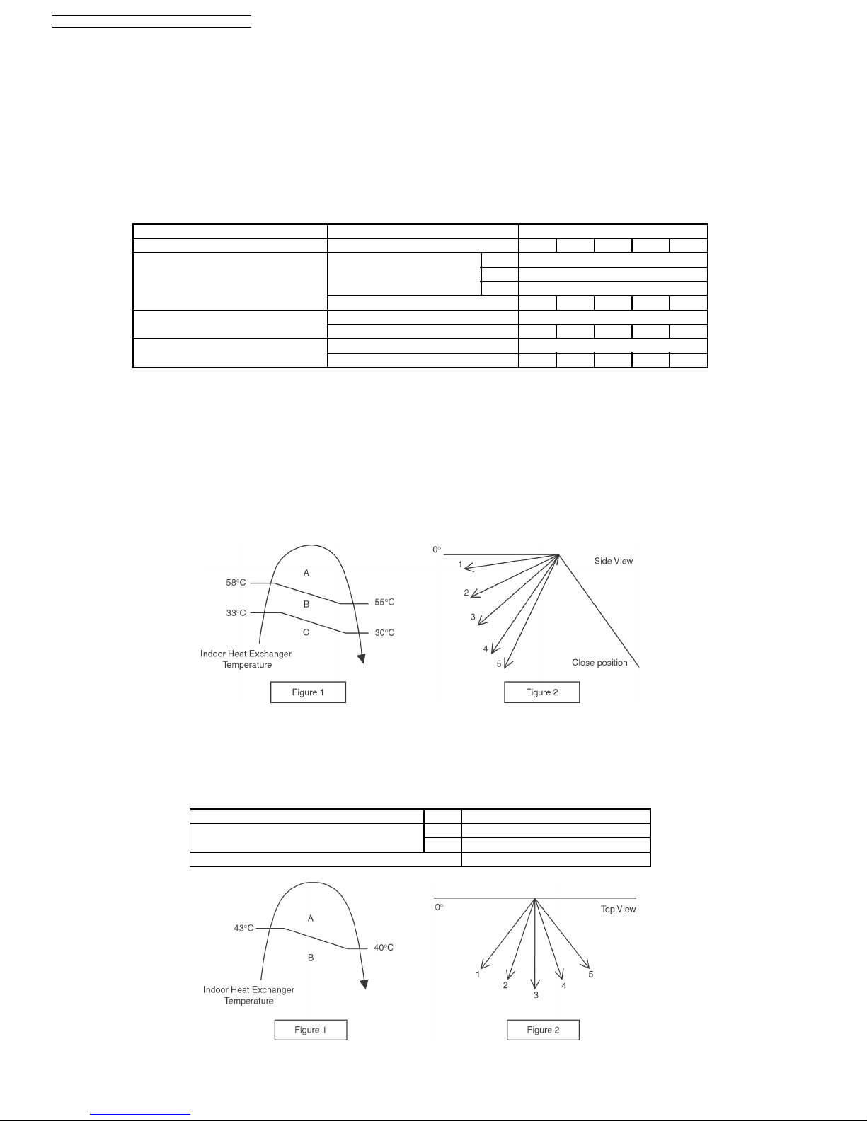
8.1.7. Airflow Direction
1. There are two types of airflow, vertical airflow (directed by horizontal vane) and horizontal airflow (directed by vertical vanes).
2. Control of airflow direction can be automatic (angles of direction is determined by operation mode, heat exchanger temperature
and intake air temperature) and manual (angles of direction can be adjusted using remote controller).
Vertical Airflow
Operation Mode Airflow Direction Vane Angle (°)
1 2 3 4 5
Heating Auto, with Heat Exchanger A 17
Temperature B 58
C 7
Manual 7 17 33 49 67
Cooling, Soft Dry and Fan, Ion Auto 7~37
Manual 7 17 25 33 41
Mode Judgment in Auto Auto 7
Manual 7 17 25 33 41
1. Automatic vertical airflow direction can be set using remote controller; the vane swings up and down within the angles as
stated above. For heating mode operation, the angle of the vane depends on the indoor heat exchanger temperature as
Figure 1 below. When the air conditioner is stopped using remote controller, the vane will shift to close position.
2. Manual vertical airflow direction can be set using remote controller; the angles of the vane are as stated above and the
positions of the vane are as Figure 2 below. When the air conditioner is stopped using remote controller, the vane will shift
to close position.
Horizontal Airflow
1. Automatic horizontal airflow direction can be set using remote controller; the vane swings left and right within the angles as
stated below. For heating mode operation, the angle of the vane depends on the indoor heat exchanger temperature as
Figure 1 below.
Operation Mode Vane Angle (°)
Heating, with heat exchanger temperature A 55 ~ 125
B 90
Cooling, Soft Dry and Fan, Ion 55 ~ 125
24
CS-E9CKP CU-E9CKP5 / CS-E12CKP CU-E12CKP5
Panasonic ilmalämpöpumput korjaa ja huoltaa pääkaupunkiseudulla: Jäähdytinpalvelu RefGroup Oy
www.ilmalämpöpumput.com
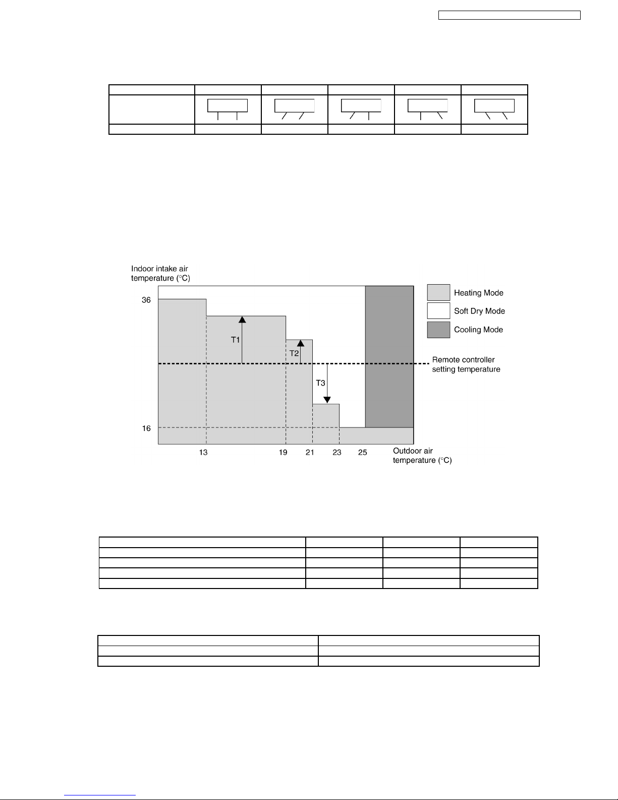
2. Manual horizontal airflow direction can be set using remote controller; the angles of the vane are as stated below and the
positions of the vane are as Figure 2 above.
Pattern 1 2 3 4 5
Airflow Direction
Patterns at Remote
Controller
Vane Angle (°) 90 55 70 110 125
8.1.8. Automatic Mode Operation
This mode can be set using remote controller and the operation is decided by remote controller setting temperature, indoor intake
air temperature and outdoor air temperature.
During operation mode judgment, indoor fan motor (with speed of Lo-) and outdoor fan motor are running for 20 seconds to detect
the indoor intake and outdoor air temperature. The operation mode is decided based on below chart.
Values of T1, T2, and T3 depend on remote controller setting temperature, as shown in below table. After the adjustment of T1,
T2 and T3 values, the operation mode for that particular environment and remote controller setting is judged and performed, based
on the above operation mode chart, every 30 minutes. Heating mode operation will be performed, however, if deice operation is
detected.
Remote Controller Setting Temperature (°C) T1 T2 T3
16 ~ 18 +10 +8 -5
19 ~ 22 +8 +7 -7
23 ~ 26 +7 +6 -7
27 ~ 30 +6 +5 -8
There is a temperature shifting on T1, T2, and T3 if the operation mode judged is changed from Cooling/Soft Dry to Heating or vice
verse.
Operation Mode change from Temperature shifts (°C)
Cooling/Soft Dry→Heating -2
Heating→Cooling/Soft Dry +2
Example of operation mode chart adjustment:
From the above table, if remote controller setting temperature = 25,
T1 = 25 + 7 = 32; T2 = 25 + 6 = 31; T3 = 25 - 7 = 18
25
CS-E9CKP CU-E9CKP5 / CS-E12CKP CU-E12CKP5
Panasonic ilmalämpöpumput korjaa ja huoltaa pääkaupunkiseudulla: Jäähdytinpalvelu RefGroup Oy
www.ilmalämpöpumput.com
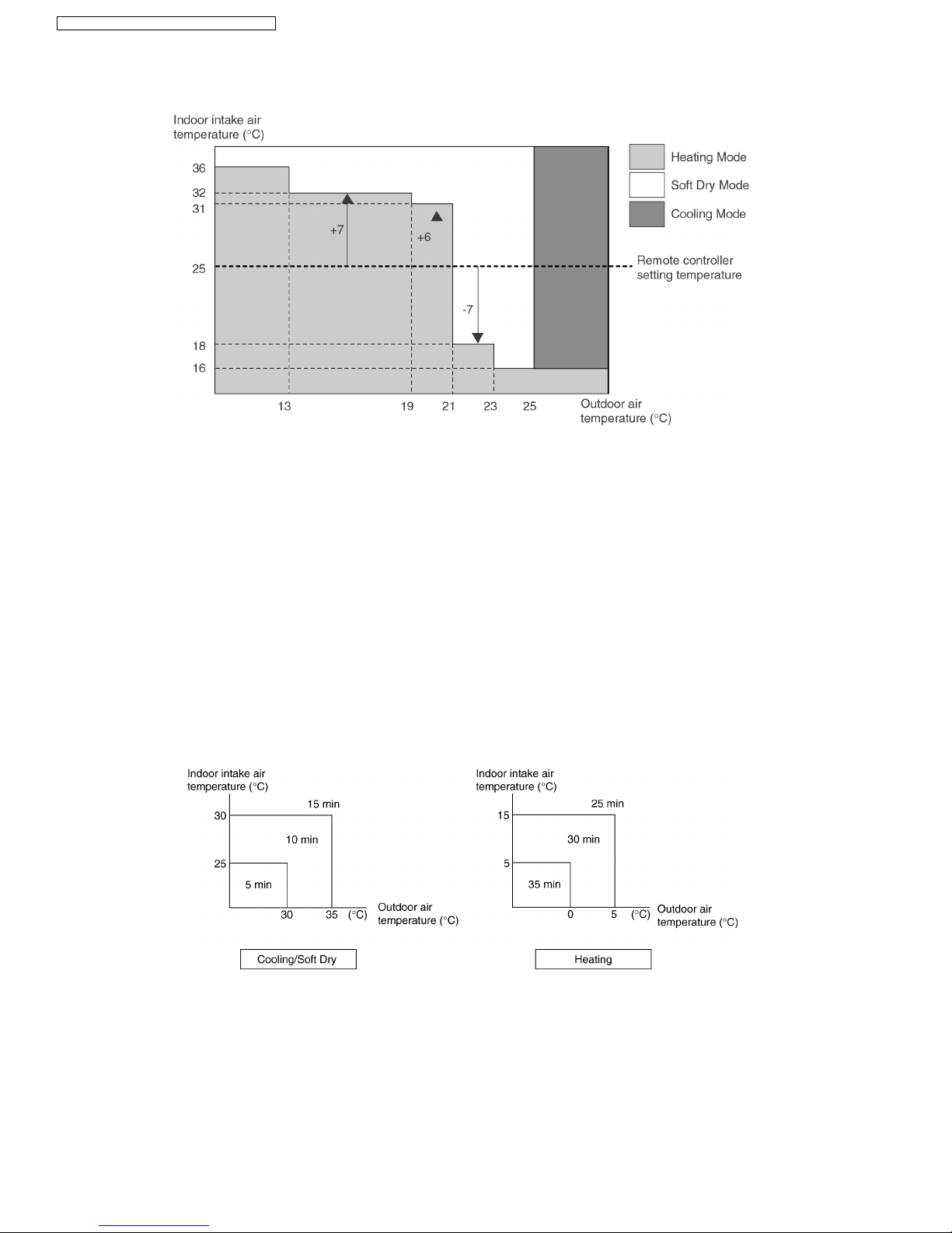
The operation mode chart for this example is as shown in below figure and the operation mode to be performed will depend on
indoor intake air temperature and outdoor air temperature at the time when the judgment is made.
8.2. Protection Control Features
8.2.1. Delay ON Timer Control
This control is applica ble to all kinds of operation mode.
Delay ON timer can be set using remote controller, the unit with timer set will start operate earlier than the setting time. This is to
provide a comfortable environment when reaching the set ON time.
Seventy minutes before the set time, indoor (at fan speed of Lo-) and outdoor fan motor start operate for 20 seconds to determine
the indoor intake air temperature and outdoor air temperature in order to judge the operation mode.
From the above judgment, the decided operation will start operate earlier than the set time as shown below.
8.2.2. OFF Timer Control
This control is applica ble to all kinds of operation mode.
OFF timer can be set using remote controller, the unit with timer set will stop operate at set time.
26
CS-E9CKP CU-E9CKP5 / CS-E12CKP CU-E12CKP5
Panasonic ilmalämpöpumput korjaa ja huoltaa pääkaupunkiseudulla: Jäähdytinpalvelu RefGroup Oy
www.ilmalämpöpumput.com
8.2.3. Indoor Power Relay Control
Power relay will turn on during operation or in progress of stopping operation. Although operation stops, the power relay continues
on for three minutes.
However, during instantaneous power failure (< 0.5s), power relay will turn off. Then, it will turn on 3 minutes after power recover
and the unit will operate as previous operation conditio n.
8.2.4. Time Delay Safety Control
This control is applica ble to all kinds of operation mode.
1. The compressor will not start for three minutes after stop of operation.
2. This control is not applicable if the power supply is cut off and on again or after 4-way valve deices condition.
8.2.5. 30 Seconds Forced Operation
This control is applica ble to all kinds of operation mode.
1. Once the compressor starts operation, it will not stop its operation for 30 seconds.
2. However, it can be stopped using remote control or Auto Switch at indoor unit.
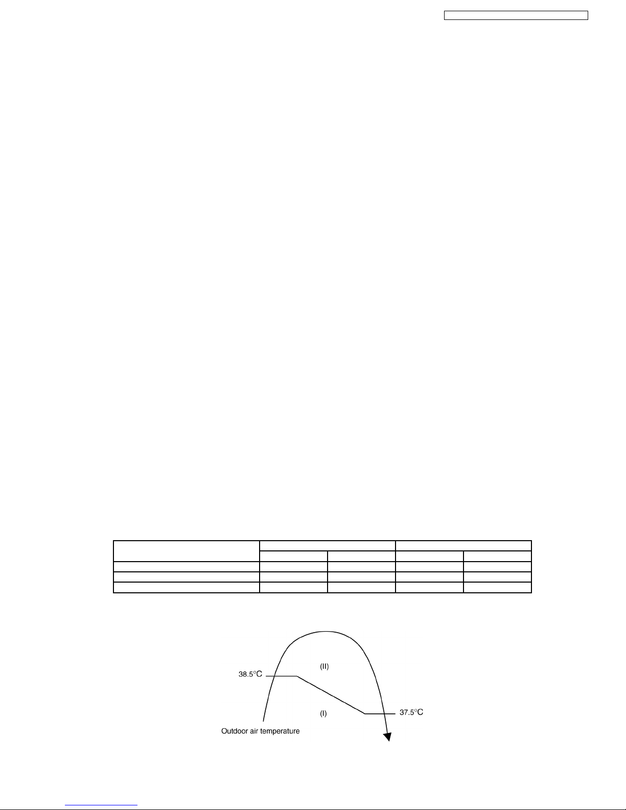
8.2.6. Total Running Current Control
This control is applica ble to all kinds of operation mode.
1. When the total outdoor unit running current (AC) exceeds X value, the frequency instructed for compressor operation will be
decreased a step to smaller frequency number.
2. If the running current does not exceed X value for five seconds, the frequency instructed will be increased a step at one time
to bigger frequency number.
3. However, if total outdoor unit running current exceeds Y value, compressor will be stopped immediately for three minutes.
Operation Mode E9CKP E12CKP
X(A) Y(A) X(A) Y(A)
Cooling/Soft Dry (I) 4.5 17.0 6.5 17.0
Cooling/Soft Dry (II) 4.0 17.0 6.0 17.0
Heating 6.1 17.0 9.2 17.0
4. The first 30 minutes of cooling operation, (I) will be applied.
27
CS-E9CKP CU-E9CKP5 / CS-E12CKP CU-E12CKP5
Panasonic ilmalämpöpumput korjaa ja huoltaa pääkaupunkiseudulla: Jäähdytinpalvelu RefGroup Oy
www.ilmalämpöpumput.com

8.2.7. IPM (Power transistor) Prevention Control
This control is applica ble to all kinds of operation mode.
A. DC Peak Current Control
1. When electric current to IPM exceeds set value of 22.5 ± 3.5 A, the compressor will stop operate. Then, operation will restart
after three minutes.
2. If the set value is exceeded again within 30 seconds after the compressor starts, the operation will restart after one minute.
If this conditio n repeats continuously for seven times, all indoor and outdoor relays will be cut off.
B. Overheating Prevention Control
1. When the IPM temperature rises to 110°C, compressor operation will stop immediately.
2. Compressor operation restarts after three minutes the temperature decreases to 95°C.
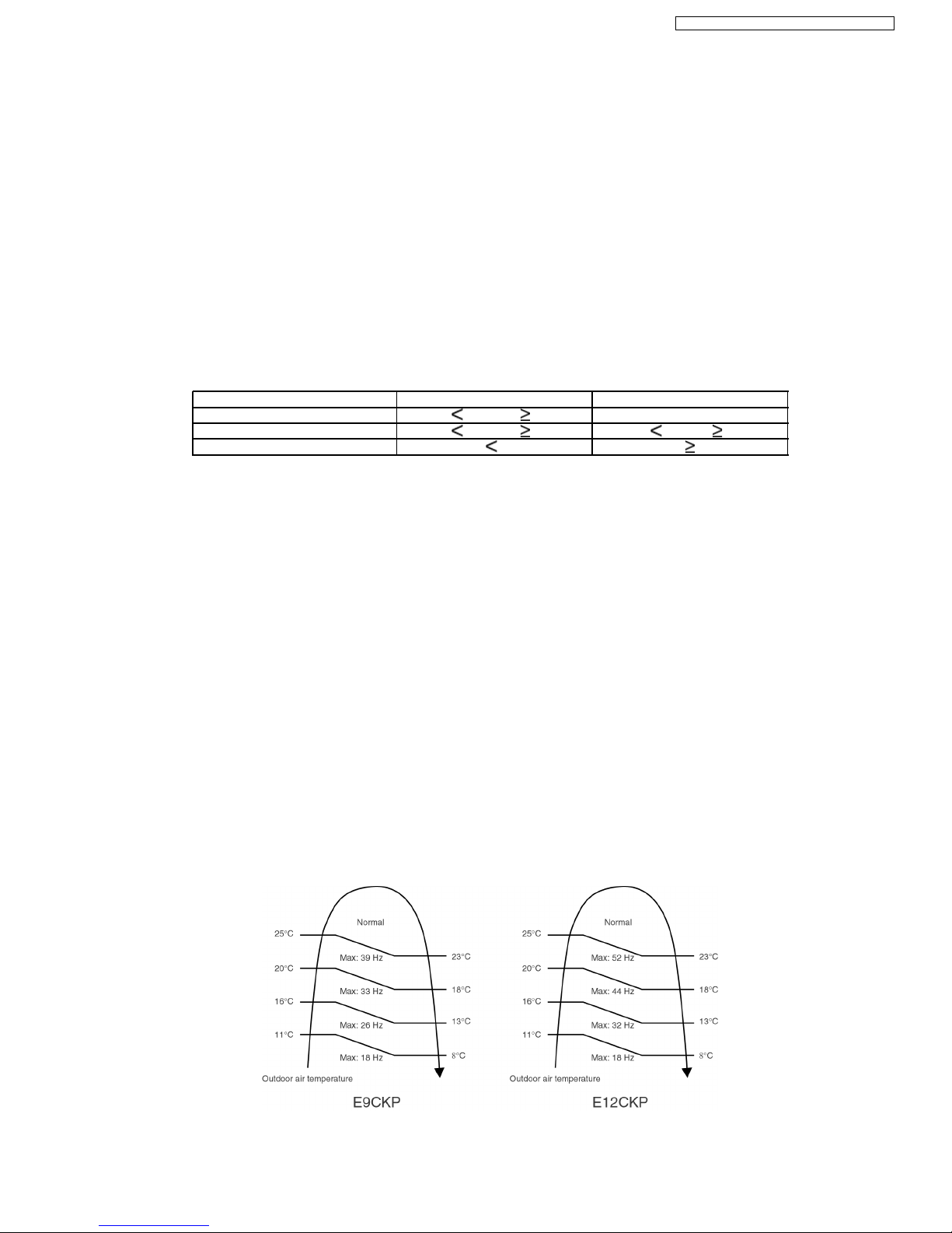
8.2.8. Compressor Overheating Prevention Control
This control is applica ble to all kinds of operation mode.
Instructed frequency for compressor operation will be regulated by compressor discharge temperature. The changes of frequency
are as below figure.
8.2.9. Low Pressure Control (Gas Leakage Detection)
This control is applica ble to all kinds of operation mode.
1. When the conditions listed in below table occur, the compressor stops and restarts after three minutes.
2. If this phenomenon is continuously occurring for twice within 20 minutes, all indoor and outdoor relays will be cut off.
3. This control is not applica ble for deice operation.
Conditions E9CKP E12CKP
Cooling/Soft Dry Heating Cooling/Soft Dry Heating
1. Compressor frequency (Hz) 47 56 67 68.5
2. Outdoor total running current (A) 1.21 1.21 1.21 1.21
3. Indoor heat exchanger temperature 25 25 25 25
Note: Conditions 1 and 2 needed to be happened continuously for 5 minutes.
28
CS-E9CKP CU-E9CKP5 / CS-E12CKP CU-E12CKP5
Panasonic ilmalämpöpumput korjaa ja huoltaa pääkaupunkiseudulla: Jäähdytinpalvelu RefGroup Oy
www.ilmalämpöpumput.com
8.2.10. Minimum Operation Frequency Protection Control
This control is applica ble to all kinds of operation mode.
When the compressor operate at frequency lower than 26 Hz (E9CKP ) or 28 Hz (E12CK P) for 240 minutes, the operation
frequency will be increased to 26 Hz (E9CKP ) or 28 Hz (E12CK P) for two minutes.
8.2.11. Low Operation Frequency Protection Control
This control is applica ble to all kinds of operation mode.
When all the below conditions occur, minimum value (Freq. MIN) for the frequency instructed to compressor will change to 30 Hz
(E9CKP) and 32 Hz (E12CK P) for cooling mode operation, and 21 Hz (E9CKP & E12CKP) for heating mode operation.
Temperature, T, for: Cooling/Soft Dry Heating
Indoor intake air (°C) T 15 or T 30 —
Outdoor air (°C) T 16 or T 38 T 4orT 24
Indoor heat exchanger (ºC) T 30 T 0
8.2.12. Auto Restart Control
This control is applica ble to all kinds of operation mode.
1. When the power supply is cut off during the operation of air conditioner, the compressor will re-operate within three to four
minutes (there are 10 patterns between 2 minutes 58 seconds and 3 minutes 52 seconds to be selected randomly) after power
supply resumes.
2. This type of control is not applicable during ON/OFF Timer setting.
8.2.13. Outdoor Air Temperature Control
1. For Cooling Mode and Soft Dry Mode operation, the compressor operating frequency is regulated in accordance to the outdoor
air temperature as shown in the diagram below. This control will begin one minute after the compressor starts.
29
CS-E9CKP CU-E9CKP5 / CS-E12CKP CU-E12CKP5
Panasonic ilmalämpöpumput korjaa ja huoltaa pääkaupunkiseudulla: Jäähdytinpalvelu RefGroup Oy
www.ilmalämpöpumput.com
 Loading...