

Page 1

Order No: PAPAMY1503095CE
TEM P
O
TIMER
S
O
N
O
1
2
C
K
Installation Manual
Air Conditioner
Indoor Unit Outdoor Unit
CS-E12RB4UW
CS-E18RB4UW
CU-E12RB4U
CU-E18RB4U
E
S
O
L
C
N
E
P
O
N
E
P
O
E
S
O
L
C
O
F
F
/
O
N
A
I
R
T
I
S
M
P
W
O
E
R
W
I
N
E
G
R
AUTO
HEAT
COOL
DRY
FAN
MODE
POWERFUL/
QUIET
TIMER
123
FF
SETCHECK CLOCK RESET
FAN
SPEED
AIR
SWING
OFF/ON
FF/ON
TEMP
AIRSWING
FANSPEED
ET
SET
3
CANCEL
CANCELONOFF
AC RC
HEC
Destination
USA
Canada
WARNING
This service information is designed for experienced repair technicians only and is not designed for use by the general public.
It does not contain warnings or cautions to advise non-technical individuals of potential dangers in attempting to service a product.
Products powered by electricity should be serviced or repaired only by experienced professional technicians. Any attempt to service
or repair the products dealt with in this service information by anyone else could result in serious injury or death.
PRECAUTION OF LOW TEMPERATURE
In order to avoid frostbite, be assured of no refrigerant leakage during the installation or repairing of refrigerant circuit.
© Panasonic Corporation 2015
Page 2

11. Installation Instruction
11.1 Indoor Unit
11.1.1 Selecting the Location for the Indoor Unit
Provide a check port on the piping side ceiling for repair and maintenance.
Install the indoor unit once the following conditions are satisfied and after receiving the customer approval.
1 The indoor unit must be within a maintenance space.
2 The indoor unit must be free from any obstacles in path of the air inlet and outlet, and must allow spreading
of air throughout the room.
3 Mount with the lowest moving parts at least 8 ft (2.4 m) above floor or grade level.
"
16
/
13
/16"
11
(300) or less
(Unit: inch (mm))
(Unit: inch (mm))
Obstacles
3
/8"
39
(1000)
or more
11
/16"
Floor
19
(500) or
more
"
8
/
1
96"–118
(2400 – 30 00)
1911/16"
(500) or
more
11
19
(500) or
more
* If the height from the floor to ceiling ex
ecreased
d
.
ceeds three meters, air flow distribution deteriorates a
nd the effect is
4 The installation position must be able to support a load four times the indoor unit weight.
5 The indoor unit must be away from heat and steam sources, but avoid installing it near an entrance.
6 The indoor unit must allow easy draining.
7 The indoor unit must allow easy connection to the outdoor unit.
8 Place the indoor unit according to the height from the ceiling shown in the illustration below.
9 The indoor unit must be from at least 9.8 ft (3 m) away from any noise-generating equipment. The electrical
wiring must be shielded with a steel conduit.
10 If the power supply is subject to noise generation, add a suppressor.
11 Do not install the indoor unit in a laundry. Electric shocks may result.
Note
Thoroughly study the following installation locations
1
In such places as restaurants and kitchens, considerable amount of oil steam and flour adhere to the turbo
fan, the fin of the heat exchanger and the drain pump, resulting in heat exchange reduction, spraying,
dispersing of water drops, drain pump malfunction, etc.
In these cases, take the following actions:
o Make sure that the ventilation fan for smoke-collecting hood on a cooking table has sufficient capa
that it draws oily steam wh
o Make enough distance from the cooking room to install the air conditioner in such place wher
su
ck in oily steam.
Air conditioner
ich should not flow into the suction of the air conditioner.
e it may not
city so
Ensure ample
distance
2 Avoid installing the air conditioner in such
circumstances where cutting oil mist or iron
powder exist especially in factories, etc.
3 Avoid places where inflammable gas is
generated, flows-in, contaminated, or leaked.
4 Avoid places where sulphurous acid gas or
corrosive gas can be generated.
5 Avoid places near high frequency generators.
Cooking table
29
Use the ventilation fan for smokecollection hood with sufficient capacity.
collectionhoodwithsufficientcapacity.
Model Name Height in the ceiling
E12***
E18***
11" (280 mm) or
more
Page 3
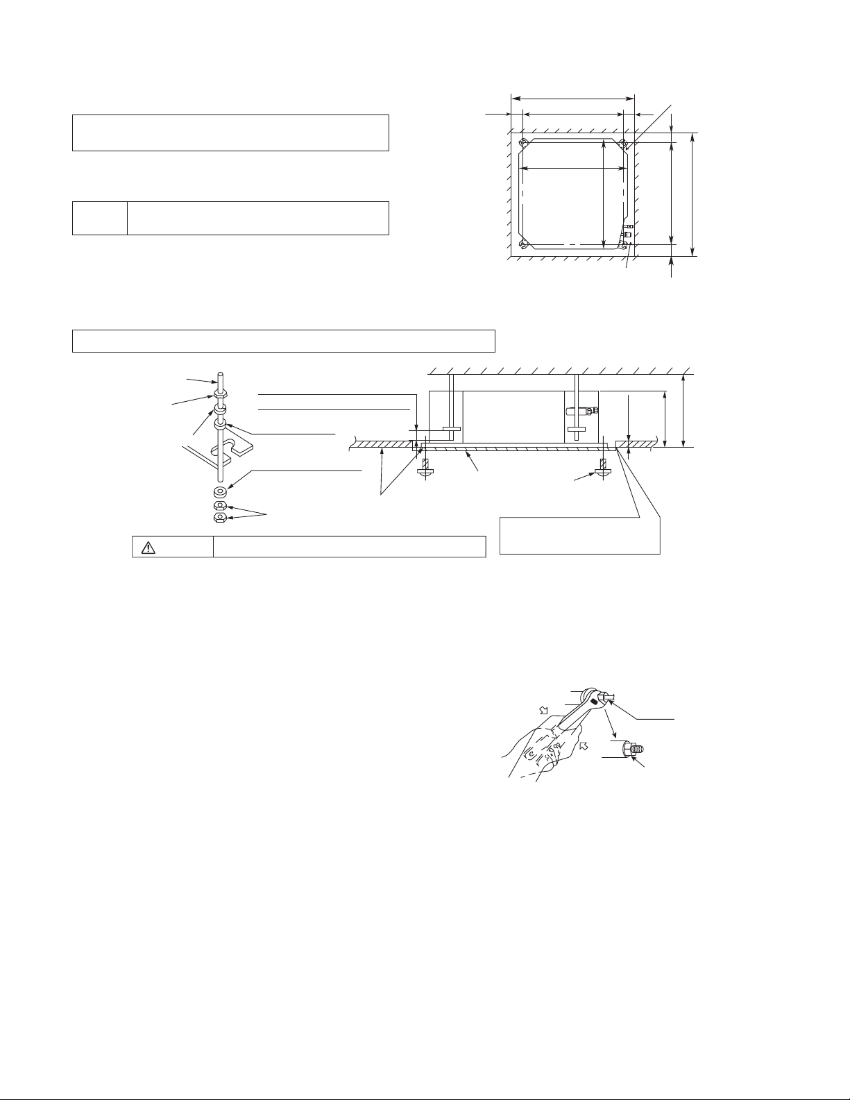
11.1.2 Installation of Indoor Unit
n
nch
H
andabove
piping
This air conditioner uses a drain up motor.
Horizontally install the unit using a level gauge.
CEILING OPENING DIMENSIONS AND
BOLT LOCATION
The paper model for installation expand or shrink
according to temperature and humidity.
Check on dimensions before using it.
Caution
During the installation, care must be taken
not to damag
e electric wires.
The dimensions of the paper model for installation
are the same
imensions
d
Be sure to discuss the ceiling drilling work
worke
rs concerne
as those of the ceiling opening
.
d.
POSITIONS OF AIR CONDITIONER BODY AND CEILING SURFACE
HANGING
with the
259/16" (650) (Ceiling opening)
23/8"
(60)
7
/8" (530)
20
(Hanging bolt)
2213/16" (580)
(Unit size)
(U
" (580)
16
/
13
(Unit size)
22
Refrigerant pipe
2
(60)
it: i
3
/8"
Drain pipe
23/8"
(60)
" (530)
8
/
7
20
(Hanging bolt)
"
8
/
3
(mm))
(60)
9
" (650) (Ceiling opening)
16
/
25
angingbolt
(W3/8 or M10)
Nut
(W3/8 or M10)
M10Springwasher
Warning
Keep the length of the bolt from
9
the bracket to 1
Flat washer for M10
(accessory)
Flat washer for M10
(accessory)
Nut
(W3/8 or M10)
/16" (40 mm)
Ceiling
Adjust to the same height
Paper model
for installation
Tighten the nut and bolt to prevent unit from falling
Air conditioner body
Set screw for paper
model (4 pieces)
Open the ceiling board a long the
outer edge of the pa per model.
"
"
8
/
16
1
/
7
11
4
(282 mm)
(113 mm)
11.1.3 Refrigerant Piping
Refrigerant is charged to the outdoor unit. For details, see the manual for installation work of outdoor unit.
(Additional charging, etc.)
1 Brazing for piping.
a. Execute brazing before tightening the flare
nut.
b. Brazin
g must be executed whil
n gas. (This prevents generatio
nitroge
oxidized scale in copper pipe.)
2
When there is a lot of brazings for long piping,
install a strainer midway of the piping. (The
strainer is locally supplied.)
3 Use clean copper pipe with inner wall surface
free from mist and dust. Blow nitrogen gas or
air to blow off dust in the pipe before
connection.
4 Form the piping according to its routing. Avoid
bending and bending back the same piping
point more than three times. (This will result in
hardening of the pipe).
5 After deforming the pipe, align centers of the
union fitting of the indoor unit and the piping,
and tighten them firmly with wrenches.
6 Connect pipe to the service valve or ball valve
which is located below the outdoor unit.
7 After completed the piping connection, be sure to check if there is gas leakage in indoor and outdoor
connection.
e blowing
n of
Red mar k
Con• rm the red mark of the union (thin side)
•
is always at lower direction after connecting
.
Union
" (292 mm)
2
/
1
11
30
Page 4
Vacuum drying
r
w
henconnectingwithth
D
After completing the piping connection, execute vacuum drying for the connecting piping and the indoor unit.
The vacuum drying must be carried out by using the service ports of both the liquid and gas side valves.
CAUTION
Use two wrenches and tighten with regular torque.
Do not overtighten, overtightening may cause gas leakage.
Piping size Torque
1/4" (6.35 mm) 13.3 Ibf•ft [18 N•m (1.8 kgf•m)]
3/8" (9.52 mm) 31.0 Ibf•ft [42 N•m (4.3 kgf•m)]
1/2" (12.7 mm) 40.6 Ibf•ft [55 N•m (5.6 kgf•m)]
5/8" (15.88 mm) 47.9 Ibf•ft [65 N•m (6.6 kgf•m)]
3/4" (19.05 mm) 73.8 Ibf•ft [100 N•m (10.2 kgf•m)]
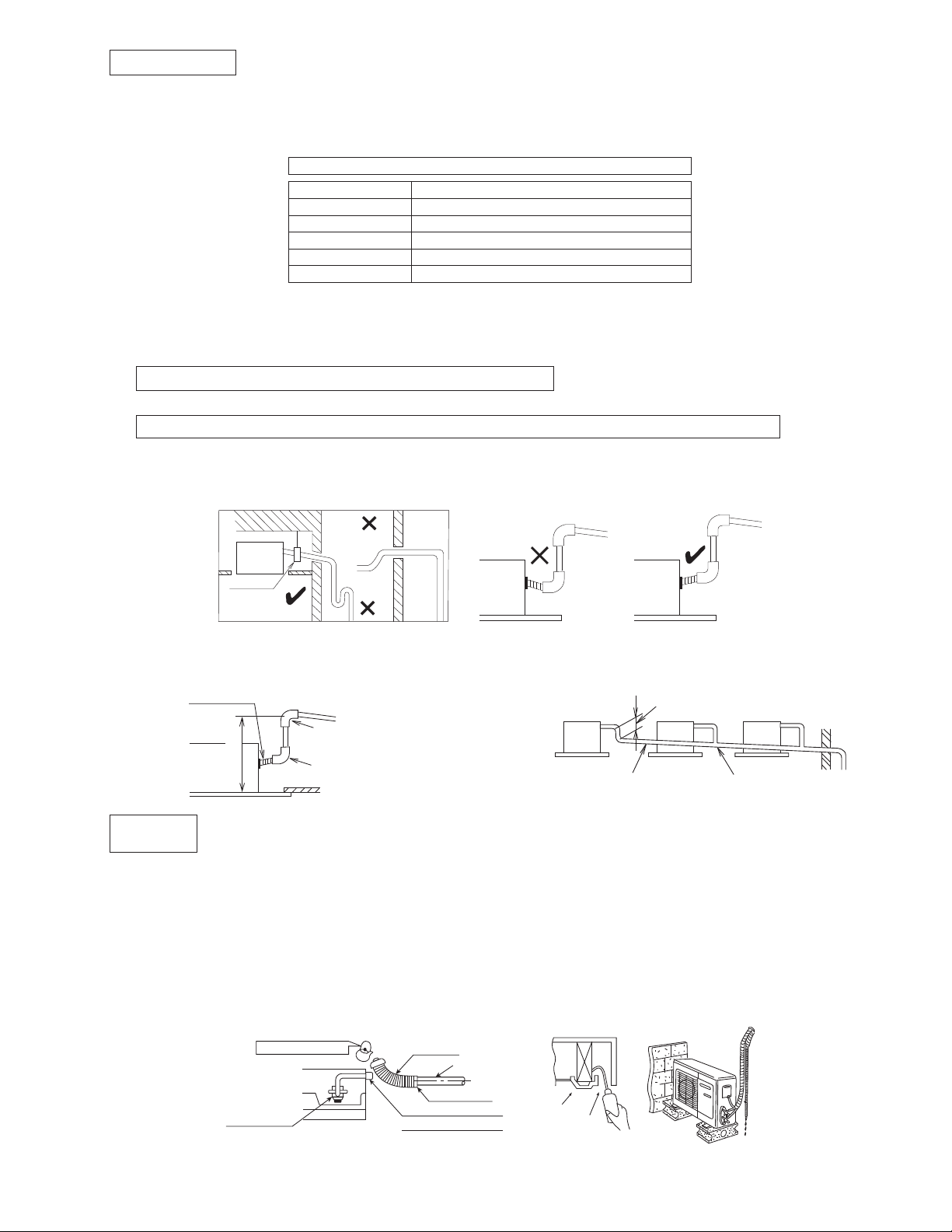
11.1.4 Indoor Unit Drain Piping
During drain piping connection, be careful not to exert extra force on the drain port at the indoor unit.
The outside diameter of the drain connection at the indoor unit is 1-1/4" (32 mm).
Piping material: Polyvinyl chloride pipe VP-25 and pipe fittings.
Be sure to perform heat insulation on the drain piping.
Heat insulation material: Polyethylene foam with thickness more than 5/16" (8 mm) (local supply).
Drain piping must have down-slope (1/50 to 1/100); be sure not to provide up-and-down slope to prevent reversal
flow.
Be sure to check no air trap on drain hose and to ensure smooth water flow and no abnormal sound.
ow.
Upward-slope
No Air Trap
Apply thehead
confluence pipe. (about 3
Use VP30 or more confluence
nd.
mplete.
the
15
/16" (100 mm))
e
Indoor
unit
Pipe clamp
Down-slope
The height of drain may be possibl
(750 mm
Drain Test
Connect the main drain pipe to exterior and leave it provisionally until the test comes to an e
Feed water to the flexible drain hose and check the piping for leaka
Be sure to check the drain up motor for normal operating and noise when electric wiring is co
When the test is complete, connect the flexible drain hose to the drain port.
).
ainport
D
Indoor unit
" (750 mm)
or less
2
/
1
29
The air conditioner uses a drain up motor to drain water. Use the following procedure to test the drain
up motor o
Upward routin g
Tra p
e up to 29-1/2"
Down-slope (1/50 ~ 1/100)
Elbow
Elbow
peration.
Down-slope
Air Trap
When drain set piping, install as shown in
figure bel
Indoor
unit
own-slope (1/50 ~ 1/100)
ge.
Pour about 600-700cc of water in the drain pan of the indoor unit. (Pour from the position specified in the drawing
by using a
Press the drain pump test run on PCB to start the drain motor, and verify water drainage.
water supply bottle or other su
itable tool.)
(The drain motor will automatically stop after operating for about five minutes.)
Feed water
Drain up motor
Drain hose
Main drain pipe
Drain
Glue the joint
port
Drain hose connection
Use the clip (accessory)
Drain pan
Air outlet vent
31
Page 5

11.1.5 Heat Insulation
u
n
pedow
n
Be sure to perform heat insulation on the drain, liquid and gas piping. Imperfection in heat insulation
work leads to water leakage.
1 Use the heat insulation material for the refrigerant piping which has an excellent heat-resistance (over 248°F
(120°C)).
Overlapwithheat
insulator for piping.
Heat insulator
for piping
(Local supply)
Heat insulator
(Accessory)
Indoor
nit
Band
(Accessory)
2 Precautions in high humidity circumstance.
This air conditioner has been tested according to the “JIS Standard Conditions with Mist” and have been
confirmed that there are no faults. However, if it is operated for a long time in high humid atmosphere (dew
point temperature: more than 73.4°F (23°C)), water drops are liable to fall. In this case, add heat insulation
material according to the following procedure:
o Heat insulation material to be prepared… Adiabatic glass wool with thickness 3/8" to 1 3/16" (10 to
20 mm).
o Stick glass wool on all air conditioners that are located in ceiling atmosphere.
o In addition to the normal heat insulation (thickness: more than 5/16" (8 mm) for refrigerant piping (gas
piping: thick piping) and drain piping, add a further of 3/8" (10 mm) to 1 3/16" (30 mm) thicknes
material.
Wall seal
When the outdoor unit is installed on a higher
positio
n than the indoor unit, install the trap so as
not to instill rain water into the wall by transmitting
in piping.
Stuff the space among piping, the electric
and- the d
rain hose with “Putty” and se
wire,
al the
penetration wall hole.
sure that rain water do not instill in
Make
to the
wall.
Hose clip (Accessory)
Heat insulator (Local supply)
(The thickness must be at
5
least
/16" (8 mm).)
It may be required to take off this par t for checking or
servicing the drain up motor. Please do not glue.
Make sure that there is no clearance here.
Pi
 Put the incision at the trap part of the heat
i
Flexible hose with
heat insulator
(Accessory)
To be glued
Indoor
unit
Drain pipe
sulator (for waterdrain)
PVC pipe
(O.D. ø1"
(ø26)
(Local
supply)
Putty
Pipe
s
Trap
Incision
32
Page 6

11.1.6 Connecting the Cable to the Indoor
cre
w
C
a
e
r
Open the control board cover by removing 2 pcs of screw.
Unscrew and open the conduit cover upper case. Remove the plug and fix the conduit connector to cond
with lock
nut.
Connecting wire between indoor unit and outdoor unit should be UL listed or CSA approved 4 conductor UL listed
or CSA app
nection cable length of each indoor unit shall be 98.4 ft (30 m) or less.
con
Secure the connection cable onto the control board with the holder (clamp
Ensure the colour of wires of outdoor unit and the terminal Nos. are the same to the indoor’s resp
roved 4 conductor wires minimum AWG16 in accordance with local electric codes. Allowabl
er).
ectively.
Earth wire shall be Yellow/Green (Y/G) in colour and longer than other AC wires for safety reason.
S
s
Terminals on the indoor unit 1 2 3
Colour of wires
Terminals on the outdoor unit 1 2 3
Wire inser tion hole
uit cover
e
WARNING
This equipment must be properly earthed.
WIRE STRIPPING,
CONNECTING
REQUIREMENT
No loose strand
when inserted
Indoor/outdoor
connection
terminal
board
7/32" (5 mm)
or more
(gap between wires)
WARNING
Do not joint wires
RISK OF FIRE
JOINING OF WIRES
MAY CAUSE
OVERHEATING AND
FIRE.
Conductor
fully inserted
ACCEPT PROHIBITED PROHIBITED
Wire stripping
(10±1 mm)
13/32" ±1/16"
Conductor
over inserted
Conductor not
fully inserted
OROR
Screw
Lock nut
Connector
inlet hole
Terminal
Installer should
open the ear th
wire screw on
the metal par t
when necessary
for installation or
service purpose.
Control box cover
Conduit Cover
upper ca se
Connector
Indoor
123
OR
Plug
Indoor-Outdoor
connection w ire
inlet
Use complete wire without joining.
Use approved socket and plug with earth pin.
Wire conn e ction in this area m ust follow t o
national wiring rules.
11.1.7 Installation of Decorative Panel
The decorative panel has its installation direction. Confirm the direction by displaying the piping side.
1 Remove the air inlet grille by moving the catchers to center.
Air inlet grill
tch
Decorative panel
Hinge
Air inlet grill
* Hang the hinge on the hole of
decorative panel. (The direction of
the insta lla tion is free.)
33
Page 7

2 Fitting the decorative panel
ram
e
C
N-STM
2
r
o Temporarily secure the fixing scre
pcs.) before fitting the decorative panel.
ws (3
Securing the tentative
fixing screw
Approx. 3/4" (20 mm)
(For temporarily securing the front grille.)
o
Place decorative panel on the scre
pcs.) befo
panel a
sc
rews (4 pcs.
Check beforehand the height from the ce
re fitting, move decor
s illustrated and tigh
).
ws (3
ative
ten all the
iling to
Piping
direction
the unit.
The front grille fitting direction is determi
the unit direction.
Only use the screws with the length of 1-3/8"
(35 mm) which is provided,
to fix the decorative
panel.
Do not use other screw which is longe
se damage to the drain-pan and othe
cau
ned by
r it may
r
Decorative
Pane l m ovin g
direction
Front grille fixing
scews (4 pcs.)
Tighten this
screw first
after hanging
the grille
f
components.
3 Fit the decorative panel and ceiling wall together and confirm no gap in between. Readjust indoor unit heigh
if there is a g
ap between ceiling wall and decorative panel.
t,
Good example
Air conditioner
Air
Fit the insulator (this part) and
be careful for cool air leakage.
unit
Ceiling
Decorative
panel
4 Open the indoor control box cover by
removing 2 pcs of screw.
5 Insert firmly the connector of cosmetic louver
to indoor pcb CN-STM1, CN-STM2 and
CN-DISP.
Be caution not to clamp the cord in between
control board and control board cover.
6 After complete, install back removed part
follow opposite procedure.
Be sure to hook the air inlet grill string,
to prevent gril
l from falling and causing
injury from it.
Bad example
Cool air leakage
(no good)
Air conditioner
Air
unit
Decorative
panel
CN-STM1
CN-DISP
Clamp lead
wire with band
here
Ceiling
Hang the
string
Air inlet grille
Catcher
Catche
34
Page 8

11.2 Outdoor Unit
•
11.2.1 Select the Best Location
If an awning is built over the unit to prevent direct
sunli
ght or rain, be careful that heat radiat
the con
denser is not obstructed.
There should not be any animal or plant which
coul
d be affected by hot air discharged.
Keep the spaces indicated by arrows from
ceiling, fence or other obstacles.
Do not place any obstacles
rt circuit of the discharged air.
sho
which may cause a
If piping length is over the [piping length for
addition
adde
Model
E12*** 11900
E18*** 17500
Example: For E12***
al gas], additional refrigerant sh
d as shown in the tabl
Capacity
(Btu/h)
Piping size
Gas Liquid
1/2"
(12.7mm)
1/4"
(6.35mm)
Std.
Length
24.6 ft
(7.5 m)
Elevation
49.2 ft
(15 m)
49.2 ft
(15 m)
Max.
e.
Piping
Length
Min.
9.8 ft
(3 m)
9.8 ft
(3 m)
Max.
Piping
Length
65.6 ft
(20 m)
100 ft
(30.5 m)
If the unit is installed at 32.8 ft (10 m) distance, the
quantity of additional refrigerant should be 1.64 oz
(50 g) .... (32.8 - 24.6) ft x 0.2 oz/ft = 1.64 oz.
((10 - 7.5) m x 20 g/m = 50 g).
ion from
wall,
ould be
Additional
Refrigerant
0.2 oz/ft
(20 g/m)
0.3 oz/ft
(25 g/m)
Piping
Length for
add. gas
24.6 ft
(7.5 m)
32.8 ft
(10 m)
11.2.1.1 Indoor/Outdoor Installation
Diagram
Installation par ts you
or more
8ft(2.4m)
FloororGradelevel
Attaching the remote control holder to the wall
Remote control holder fixing screws
Remote
control
Remote contro l holder
Indoor unit
a
Outdoor
b
unit
3
1
(
5
1
0
/
1
0
6
o
"
r
m
m
m
o
)
r
Itisadvisabletoavoid
more than 2 blockage
directions.For better
ventilation & multipleoutdoor installation,
please consult
authorized dealer/
specialist.
This illustration is for explanation purposes only.
The indoor unit will actually face a different way.
e
"
)
8
/
m
3
m
e
9
r
0
3
o
0
0
m
1
r
(
o
should purchase (
Sleeve ( )
Bushing-Sleeve (
Putty (Gum Type Sealer) (
Bend the pipe as
closely on the wall as
possible, but be careful
that it doesn’t break.
Vinyl tape (Wide) (
• Apply after carrying
out a drainage test.
Saddle (
Power supply cable (
Connection cable (
1/4" Liquid side
m
m
)
r
o
e
1
1
(3
1
3
0
/
0
o
1
r
m
m
m
o
r
e
piping (
Gas side piping (
Additional drain
hose (
6
"
)
"
6
1
/
5
m
1
0
3
0
r
1
(
o
)
)
)
)
)
)
)
)
)
)
11.2.2 Install the Outdoor Unit
After selecting the best location, start installation
according to Indoo
ram.
Diag
r/Outdoor Unit Installati
1 Fix the unit on concrete or rigid fram
and ho
rizontally by bolt nut (ø10 mm).
2 When installing at roof, please consider strong
wind and earthquake.
Please fasten the installation stand firmly with
bolt or nails.
on
e firmly
35
AB
C
D
Model A B C D
"
E12***
E18***
22-7/16
(570 mm)
24-1/8"
(613 mm)
4-1/8"
(105 mm)
5-5/32"
(131 mm)
23/32"
(18.5 mm)
5/8"
(16 mm)
12-19/32
(320 mm)
14-3/16"
(360.5 mm)
"
Page 9

11.2.3 Connect the Piping
andPipeS
r
H
allU
nion
11.2.3.1 Connecting the Piping to Indoor Unit
Please make flare after inserting flare nut (locate at
joint portion of tube assembly) onto the copper pipe.
(In case of using long piping)
Connect the piping
Align the center of piping and suffici
the flare nut
with fingers.
ently tighten
Further tighten the flare nut with torque wrench in
spe
cified torque as stated in the table.
Do not overtighten, overtightening may cause gas leakage
Piping size Torque
1/4" (6.35 mm) 13.3 Ibf•ft [18 N•m (1.8 kgf•m)]
3/8" (9.52 mm) 31.0 Ibf•ft [42 N•m (4.3 kgf•m)]
1/2" (12.7 mm) 40.6 Ibf•ft [55 N•m (5.6 kgf•m)]
5/8" (15.88 mm) 47.9 Ibf•ft [65 N•m (6.6 kgf•m)]
3/4" (19.05 mm) 73.8 Ibf•ft [100 N•m (10.2 kgf•m)]
11.2.3.2 Connecting the Piping to Outdoor Unit
Decide piping length and then cut by using pipe cutter.
Remove burrs from cut edge. Make flare after
inserting the flare nut (locate at valve) onto the copper
pipe. Align center of piping to valve and then tighten
with torque wrench to the specified torque as stated in
the table.
Spanner
or Wrench
Torque wrench
11.2.3.3 Connecting the Piping to Outdoor Multi
Decide piping length and then cut by using pipe cutter. Remove burrs from cut edge. Make flare after inserting the
flare nut (locate at valve) onto the copper pipe. Align center of piping to valve and then tighten with torque wrench to
the specified torque as stated in the table.
Female sideMale side
Flare Nut
Female side
(Connection pipe)
Applicable to
Liquid side of
CS-E12***
CS-E18***
Applicable to
Gas side of
CS-E12***
CS-E18***
(Auxiliary pipe)
Wrench (Adjustable Wrench)
Male side
(Auxiliary pipe)
Wrench (Adjustable Wrench)
Torque Wrench for Flare Nut
izeReduce
Hall Union
Flare Nut
(Connection pipe)
Torque Wrench for Flare Nut
Pipe Size
Packi ng
Reducer
11.2.3.4 Gas Leak Checking
Pressure test to system to 400 PSIG with dry nitrogen, in stages. Thoroughly leak check the system.
If the pressure holds, release the nitrogen and proceed to section 11.2.4.
36
Page 10

11.2.4 Evacuation of the Equipment
r
U
r
U
WHEN INSTALLING AN AIR CONDITIONER, BE SURE TO EVACUATE THE AIR INSIDE THE INDOOR UNIT AND
PIPES in the following procedure.
Liquid side
Gas side
Two-way valve
Close
Three-way valve
Close
Outdoor unit
Vacuum
pump
Indoor unit
1 Connect a charging hose with a push pin to the Low side of a charging set and the service port of the 3-way
valve.
2 Connect the micron gauge between vacuum pump and service port of outdoor units.
3 Turn on the power switch of the vacuum pump and make sure that connect digital micron gauge and to pull
down to a value of 500 microns.
4 To make sure micron gauge a value 500 microns and close the low side valve of the charging set and turn off
the vacuum pump.
5 Disconnect the vacuum pump house from the service port of the 3-way valve.
6 Tighten the service port caps of the 3-way valve at a torque of 13.3 Ibf•ft (18 N•m) with a torque wrench.
7 Remove the valve caps of both of the 2-way valve and 3-way valve. Position both of the valves to “Open”
using a hexagonal wrench (5/32" (4 mm)).
8 Mount valve caps onto the 2-way valve and the 3-way valve.
o Be sure to check for gas leakage.
If micron gauge value does not descend 500 microns, take the following measures:
If the leak stops when the piping connections are tightened further, continue working from step 3
If the leak does not stop when the connections are retightened, re
-
-
Do not release refrigerant during piping work for installation and reinstallation.
pair location of leak.
.
- Be careful with the liquid refrigerant, it may cause frostbite.
11.2.5 Connect the Cable to the Outdoor Unit
1 Remove control board cover (Plastic and Metal), follow by particular plate (for E18*** model).
2 Remove top panel, follow by Control Board Cover (Plastic and Metal) (for E12*** model).
3 Remove plugs.
4 Fix the conduit connectors to the knockout holes with lock-nuts, then secure them against the side panel.
5 All wires pass through conduits & particular plate’s opening hole.
6 Connecting wire between indoor unit and outdoor unit should be UL listed or CSA approved 4 conductor
wires minimum AWG16 in accordance with local electric codes.
7 Wire connection to the power supply (208/230V 60Hz) through circuit breaker.
o Connect the UL listed or CSA approved wires minimum AWG14 (for E12***) and AWG12 (for
the terminal b
8 Connect the power supply cord and connecting wire between indoor unit and outdoor unit according to the
diagram below.
oard, and connect the other end of the wires to EL
Indoo
nit
1
2
3
208/230V min AWG16
208/230V min AWG16
208/230V min AWG16
GroundingwireminAWG16
* The wires between the indoor and
outdoor unit can be installed in the
same conduit but the power supply
for the outdoor unit must be in a
separate conduit to prevent potential
communication problems.
Outdoo
1
2
3
L1
L2
nit
lanimreTlanimreT
Disconnect
Switch
Field supply
Grounding wire
CB / GFCI.
Power Supply Single
Phase 208/230V 60Hz
min AWG14 (for E12***)
and AWG12 (for E18***)
E18***) to
37
Page 11

9 Secure the wire onto the control board with the holder (clamp).
C
e
c
r
e
e
arefullyche
are
mproperfla
rin
g
10 After completing wiring connections, reattach the particular plate and control board cover (metal and plastic)
to the original position with the screws.
11 For wire stripping and connection requirement, refer to instruction 11.1.6 of indoor unit.
Front Panel
Particular Plate
Lock Nuts
Knockout
Holes
WARNING
This equipment must be properly earth grounded.
Ground lead wire shall be Yellow/Green (Y/G) in colour and longer
•
than other lead wires for electrical safety in case of the slipping.
onn
tingWi
s
Control Board
Cover (Metal)
Control Board Cover (Plastic)
wire clip
Plugs
Connectors
Particular Plate’s
opening holes
applicable for E18***
Terminal
Board
Ground
wire longer
than other
AC wir es
for sa fety
reasons
Holder
Make sure all power
•
supply and indoor
outdoor connecting
wires are guided
through wire clip which
is located near opening
hole internally.
Make sure all wires do
•
not have excess length
internally.
Power supply
cord
Control Board
Cover (Plastic)
Indoor & outdoor
connection cable
Control Board
Metal Cover
Term i nal
Board
Ground
wire longer
than other
AC wir es
for safety
reasons
Holder
Top Panel
Connectors
applicable for E12***
Connecting
Wires
Lock Nuts
Knockout
Holes
Plugs
Side Panel
11.2.6 Pipe Insulation
1 Please carry out insulation at pipe connection portion as mentioned in Indoor/Outdoor Unit Installation
Diagram. Please wrap the insulated piping end to prevent water from going inside the piping.
2 If drain hose or connecting piping is in the room (where dew may form), please increase the insulation by
using POLY-E FOAM with thickness 1/4" (6 mm) or above.
11.2.6.1 Cutting and Flaring the Piping
1 Please cut using pipe cutter and then remove the burrs.
2 Remove the burrs by using reamer. If burrs is not removed, gas leakage may be caused.
Turn the piping end down to avoid the metal powder entering the pipe.
3 Please make flare after inserting the flare nut onto the copper pipes.
1. To cut
Pipe
Reamer
Poin t down
Bar
Clamp handle
2. To remove burrs 3. To flare
Handle
Yo ke
Core
Red arrow mark
Bar
1
/32"
0–
(0-0.5 mm)
Copper pipe
ŶI
Inclined Surface
When properly flared, the internal surface of the flare will evenly shine
and be of even thickness. Since the flare part comes into contact with
th
connections, c
damaged
ck thefl
Ŷ
Cracked Uneven
thickness
finish.
38
Page 12

11.2.7 Disposal of Outdoor Unit Drain Water
r
“AUT
O
If a drain elbow is used, the unit should be placed on a stand which is taller than 1-3/16" (3 cm).
If the unit is used in an area where temperature falls below 32°F (0°C) for 2 or 3 days in successi
recomme
nded not to use a drain elbow, for the drain water freezes and the fan will not rotate
Install the hose at an
angle so that the wate
Drain elbow
Hose
smoothly flows out.
.
11.2.8 Auto Switch Operation
The following operations can be performed by
pressing the “AUTO” switch.
1 AUTO OPERATION MODE
The Auto operation will be activated
immediately once the Auto Switch is pressed.
2 TEST RUN OPERATION (FOR PUMP
DOWN/SERVICING PURPOSE)
The Test Run operation will be activated if the
Auto Switch is pressed continuously for more
than 5 sec. to below 8 sec. A “pep” sound will
occur at the fifth sec., in order to identify the
starting of Test Run operation.
”switch
on, it is
39
 Loading...