

Panasonic CS C18DKV CS, CS C18DKV CU, CS C24DKV, CS C24DKU Service Manual
Order No. MAC0502036C1
Air Conditioner
CS-C18DKU CU-C18DKU
CS-C24DKU CU-C24DKU
CONTENTS
Page Page
1 Features 2
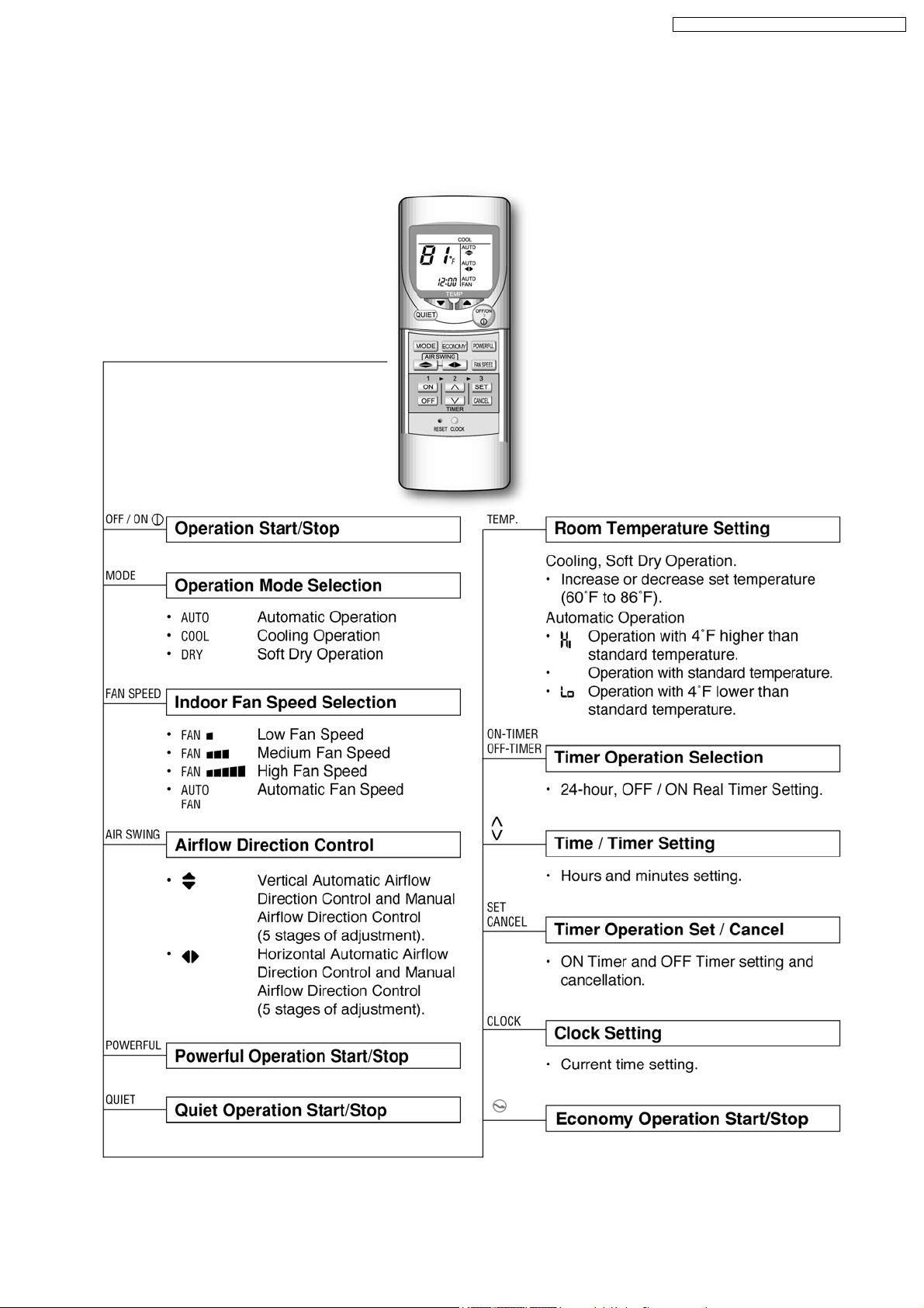
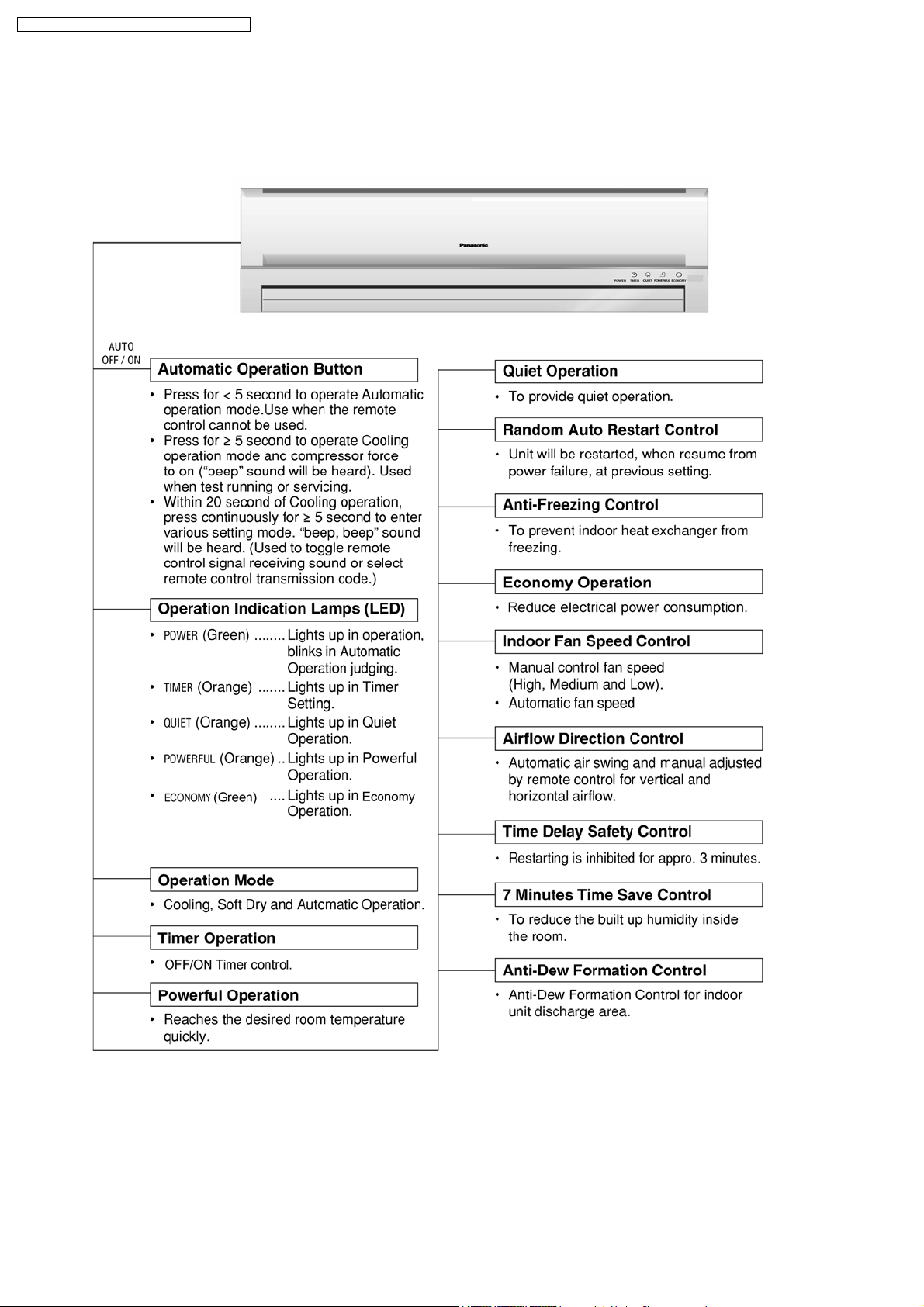
2 Functions
3 Product Specifications
3.1. CS-C18DKU CU-C18DKU
3.2. CS-C24DKU CU-C24DKU
4 Dimensions
4.1. Indoor Unit & Remote Control
4.2. Outdoor Unit
5 Refrigeration Cycle Diagram 13
3
6 Block Diagram
6
7 Wiring Diagram
6
8 Operation Details
8
10
10
11
8.1. Cooling Operation
8.2. Soft Dry Operation
8.3. Automatic Operation
8.4. Operation Control
© 2005 Panasonic HA Air-Conditioning (M) Sdn Bhd
(11969-T). All rights reserved. Unauthorized copying
and distribution is a violation of law.
14
15
17
17
18
19
20
CS-C18DKU CU-C18DKU / CS-C24D KU CU-C24DKU
8.5. Indoor Fan Speed Control 23
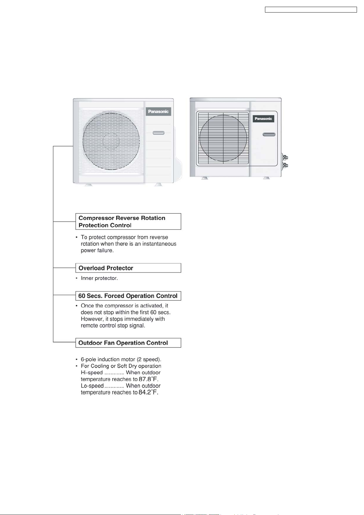
8.6. Outdoor Fan Speed Control
8.7. Vertical Airflow Direction Control
8.8. Horizontal Airflow Direction Control
8.9. Powerful Operation
8.10. Quiet Operation
8.11. Economy Mode Operation
8.12. Timer Control
8.13. Random Auto Restart Control
8.14. Remote Control Signal Receiving Sound
9 Operating Instructions
10 Installation Instructions
10.1. Safety Precautions
10.2. Indoor Unit
10.3. Outdoor Unit
11 3-way Valve
11.1. Evacuation of Installation
11.2. Pumping down
11.3. Evacuation of Re-installation
11.4. Balance refrigerant of the 3-way valves
11.5. Evacuation
11.6. Gas charging
12 Servicing Information
12.1. Indoor Electronic Controllers Removal Procedures 52
24
24
25
25
26
27
27
27
28
29
35
35
38
42
45
46
47
48
49
50
51
52
12.2. Cross Flow Fan and Indoor Fan Motor Removal
Procedures
12.3. Remote Control Reset
12.4. Auto OFF/ON Button
13 Troubleshooting Guide
13.1. Refrigeration cycle system
14 Technical Data
14.1. Thermostat characteristics
14.2. Operation characteristics
15 Exploded View (Indoor Unit)
15.1. CS-C18DKU CS-C24DKU
16 Replacement Parts List (Indoor Unit)
17 Exploded View (Outdoor Unit)
17.1. CU-C18DKU
17.2. CU-C24DKU
18 Replacement Parts List (Outdoor Unit)
19 Electronic Circuit Diagram
19.1. Indoor Unit & Outdoor Unit
19.2. Remote Control
19.3. Print Pattern Indoor Unit Printed Circuit Board
19.4. Print Pattern Indicator & Receiver Printed Circuit Board
53
54
55
56
56
58
58
59
63
63
64
65
65
66
67
69
69
74
75
76
1 Features
• High efficiency.
• Compact design.
• Wider range of horizontal discharge air.
• Air Filter with function to reduce dust and smoke.
• Automatic air swing and manual adjusted by Remote
Control for horizontal and vertical airflow.
• Long installation piping up to 82 feet.
• Quality Improvement
− Random auto restart after power failure for safety restart
operation.
− Gas leakage detection.
− Prevent Compressor reverse cycle.
− Inner protector to protect Compressor.
− Noise prevention during soft dry operation.
− Blue coated Condenser for high resistance to corrosion.
− Anti-dew formation control (Cooling & Soft Dry).
• Operation Improvement
− Quiet mode to provide quiet operation.
− Powerful mode to reach the desired room temperature
quickly.
− 24-hour timer setting.
• Serviceability Improvement
− Removable and washable Front Panel.
2
2 Functions
CS-C18DKU CU-C18DKU / CS-C24D KU CU-C24DKU
3
CS-C18DKU CU-C18DKU / CS-C24D KU CU-C24DKU
4
CS-C18DKU CU-C18DKU / CS-C24D KU CU-C24DKU
5
CS-C18DKU CU-C18DKU / CS-C24D KU CU-C24DKU
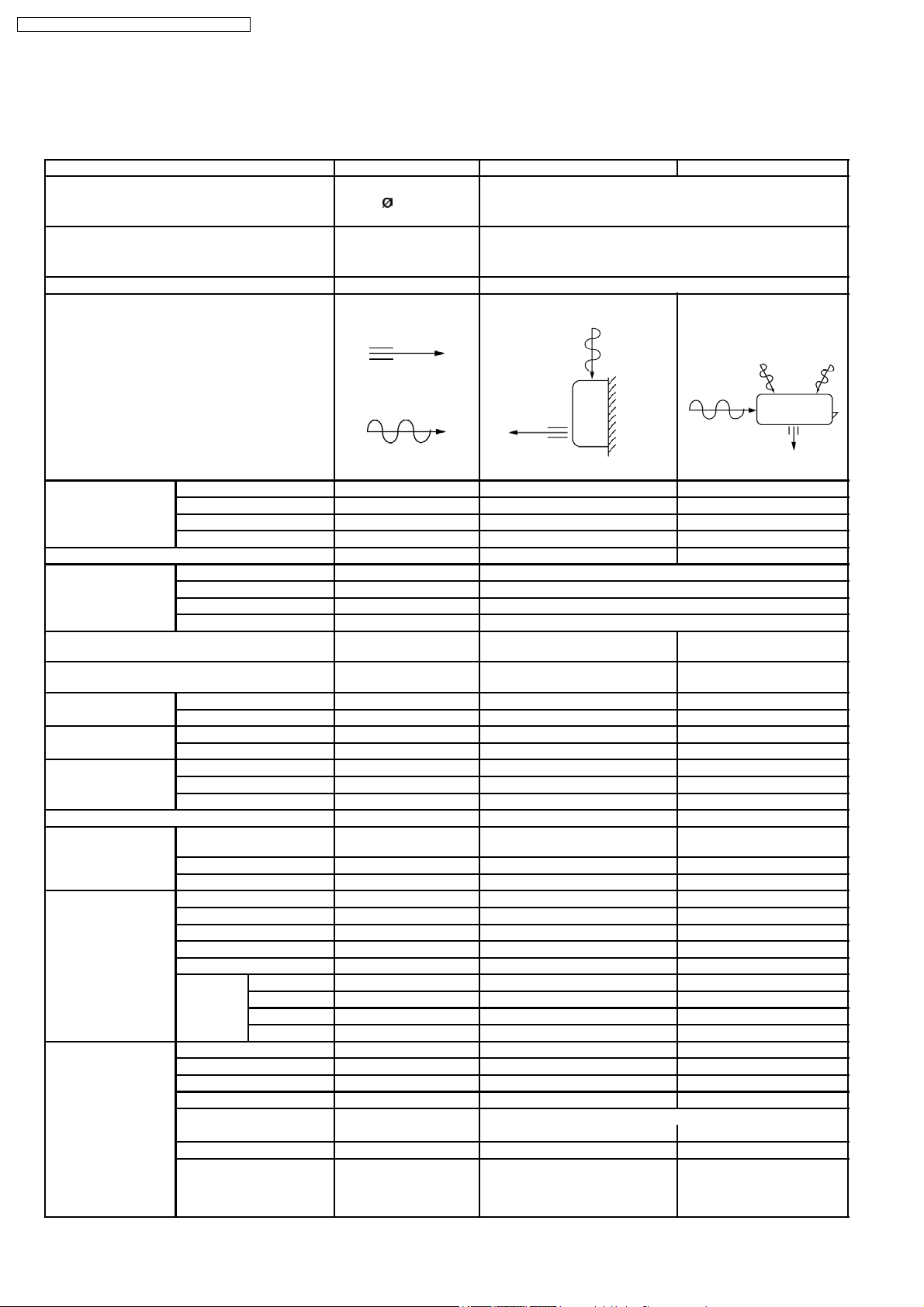
3 Product Specifications
3.1. CS-C18DKU CU-C18DKU
Unit CS-C18DKU CU-C18DKU
Power Source (Phase, Voltage, Cycle) ,V,Hz Single, 208 - 230, 60
Cooling Capacity kW (BTU/h) 5.20 (17,70 0) - 5.20 (17,700)
Moisture Removal l/h (Pint/h) 2.1 (4.4)
Airflow Method OUTLET
INTAKE
Air Volume (Lo) m3/min (cfm) 11.2 (400) - 11.2 (400) 24.1 (850) - 27.3 (960)
(Me) m3/min (cfm) 12.1 (430) - 13.6 (480) —
(Hi) m3/min (cfm) 13.1 (460) - 13.1 (460) 37.3 (1,320 ) - 39.7 (1,400)
(SHi) m3/min (cfm) 13.6 (480) - 13.6 (480) —
Noise Level dB (A) High 42 - 42, Low 37 - 37 High 54 - 56
Electrical Data Input Power kW 1.74 - 1.78
Running Current A 8.5 - 7.9
EER W/W (BTU/hW) 2.99 - 2.92 (10.15 - 9.90)
Starting Current A 47.0
Piping Connection Port
(Flare piping)
Pipe Size
(Flare piping)
Drain
Hose
Power Cord Length m — —
Dimensions Height inch (mm) 10 - 13/16 (275) 26 - 17/32 (685)
Net Weight lb (kg) 24 (11.0) 106 (48.0)
Compressor Description — Rotary (1 cylinder)
Air Circulation Description Cross-flow Fan Propeller Fan
Heat Exchanger Description Evaporator Condenser
Inner diame ter inch (mm) 6-10/32 (16) —
Length inch (mm) 25-19/32” (650) —
Number of core-wire — —
Width inch (mm) 39 - 9/32 (998) 31 - 1/2 (800)
Depth inch (mm) 9 - 1/16 (230) 11 - 13/16 (300)
Motor Type — Induction (2-poles)
Rated Output kW — 1.2
Material ASHT-18 AES + PC + GF15%
Motor Type Transistor (8-poles) Induction (6-poles)
Input W 40.0 133.3
Rated Output W 30 52
Fan Speed Low rpm 1,130 - 1,130 590/670
Medium rpm 1,220 - 1,220 —
High rpm 1,320 - 1,320 915/975
SuperHigh rpm 1,370 - 1,370 —
Tube material Copper Copper
Fin material Aluminium (Pre Coat) Aluminium (Blue Coat)
Fin Type Slit Fin Corrugated Fin
Row / Stage (Plate fin configu ration, forced draft)
FPI 21 18
Size (W × H × L) inch (mm) 31-28/32 × 12-13/32 × 1
inch
inch
inch
inch
SIDE VIEW TOP VIEW
G ; Half Union 1/2”
L ; Half Union 1/4”
G ; (gas side) 1/2”
L ; (liquid side) 1/4”
2×15 2×31
(810 × 315 × 25.4)
G ; 3-way valve 1/2”
L ; 3-way valve 1/4”
G ; (gas side) 1/2”
L ; (liquid side) 1/4”
rolling piston type
30-1/16
29-7/32
(762.4
(742.4
× 25-20/32 ×1
×651.0 ×25.4)
6
CS-C18DKU CU-C18DKU / CS-C24D KU CU-C24DKU
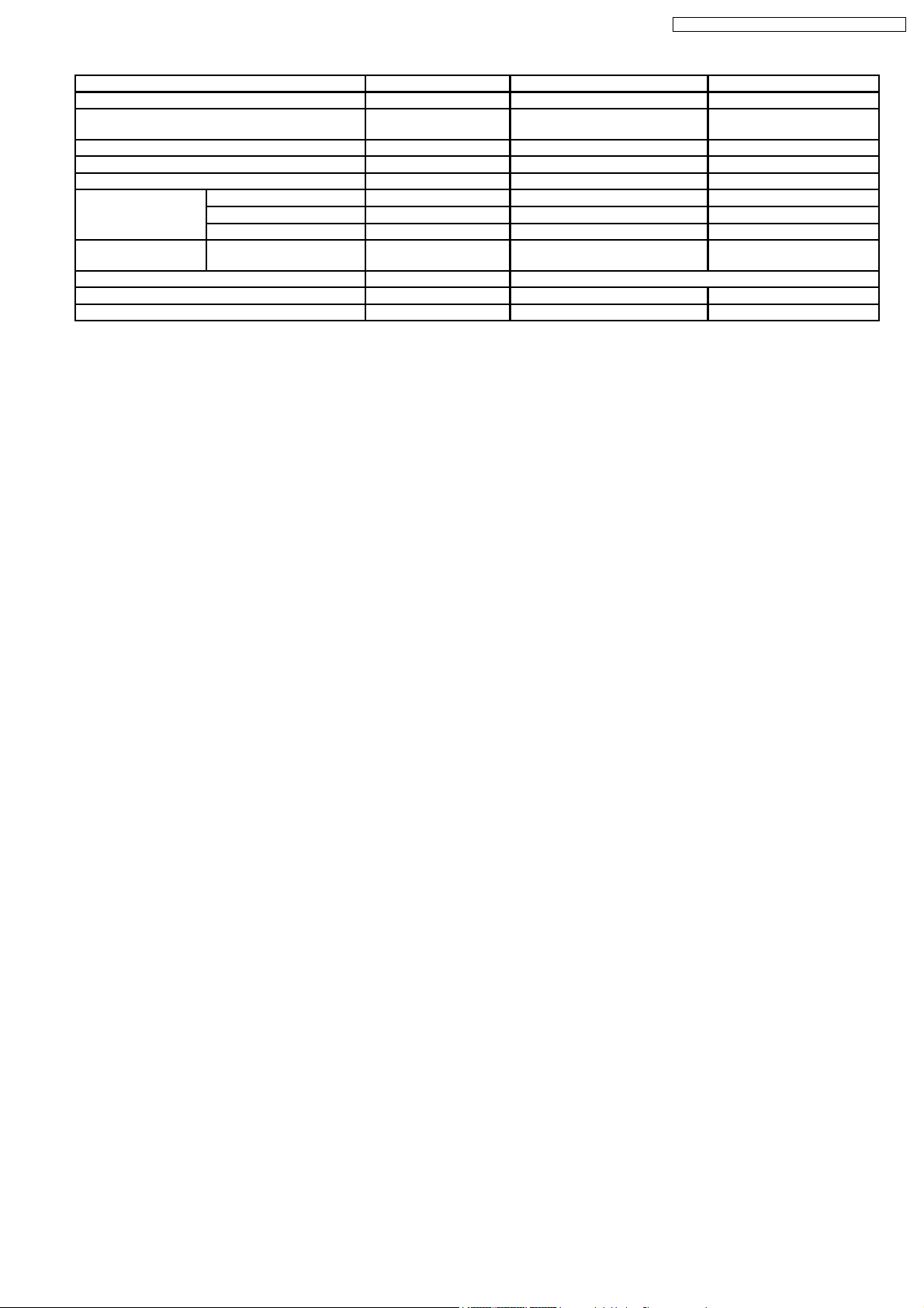
Unit CS-C18DKU CU-C18DKU
Refrigerant Control Device — Capillary Tube
Refrigeration Oil (cm3) — SUNISO 4GDID or ATMOS
Refrigerant (R-22) g (oz) — 1,240 (43.8)
Thermostat — Mechanical Control
Protection Device — Overload Protector
Capillary Tube Length inch (mm) — 25-19/32 (650)
Flow Rate l/min — 20.9
Inner Diameter inch (mm) — 2/32 (1.9)
Air Filter Material
Style
Capacity Control Capillary Tube
Compressor Capacitor µF, VAC — 40 µF, 400VA C
Fan Motor Capacitor µF, VAC — 3.0 µF, 450VAC
P.P.
Honeycomb
M60 or ATMOS 56m
—
Note:
• Specifications are subjected to change without prior notice for further improvement.
7
CS-C18DKU CU-C18DKU / CS-C24D KU CU-C24DKU
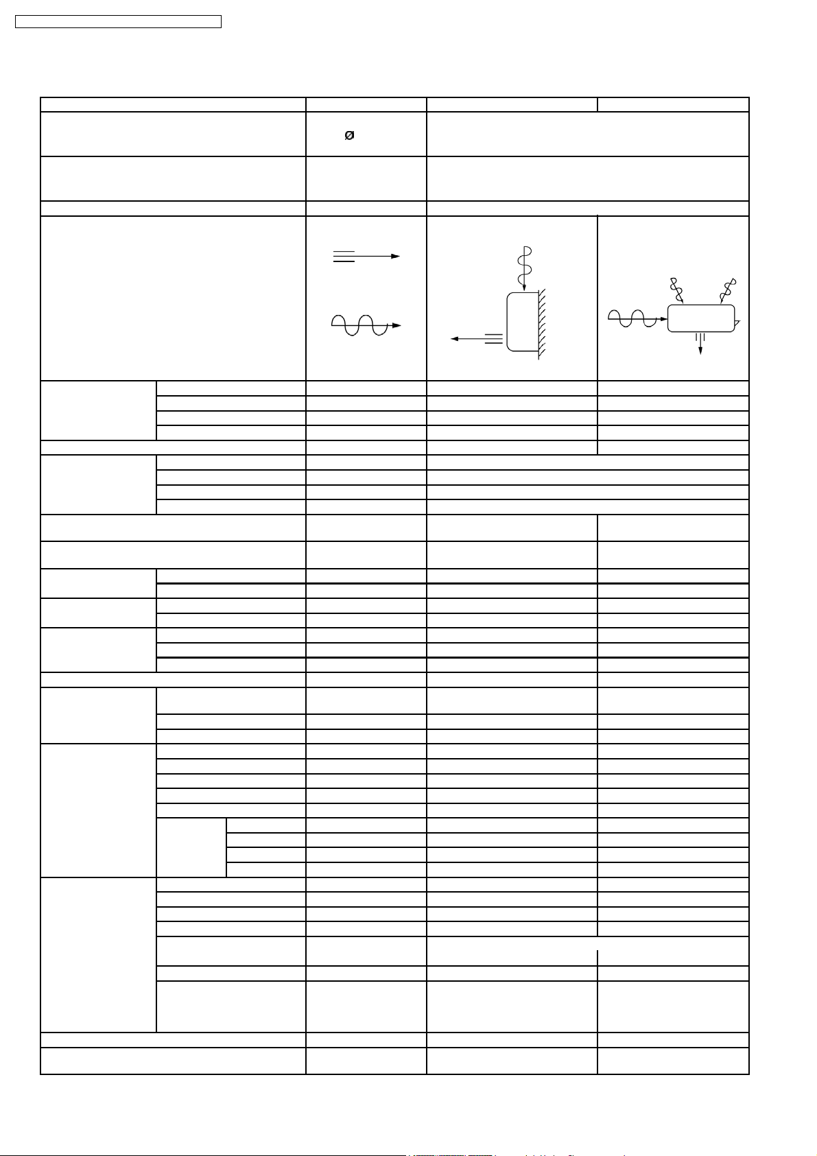
3.2. CS-C24DKU CU-C24DKU
Unit CS-C24DKU CU-C24DKU
Power Source (Phase, Voltage, Cycle) ,V,Hz Single, 208 - 230, 60
Cooling Capacity kW (BTU/h) 6.82 (23,20 0) - 6.82 (23,200)
Moisture Removal l/h (Pint/h) 3.5 (7.4)
Airflow Method OUTLET
INTAKE
Air Volume (Lo) m3/min (cfm) 12.3 (430) - 12.3 (430) —
(Me) m3/min (cfm) 13.6 (480) - 13.6 (480) —
(Hi) m3/min (cfm) 14.9 (530) - 14.9 (530) 50.5 (1,780 ) - 54.7 (1,930)
(SHi) m3/min (cfm) 15.4 (540) - 15.4 (540) —
Noise Level dB (A) High 46-46, Low 40-40 High 55 - 57
Electrical Data Input Power kW 2.64 - 2.68
Running Current A 13.1 -12.1
EER W/W (BTU/hW) 2.58 - 2.54 (8.75 - 8.65)
Starting Current A 63.0
Piping Connection Port
(Flare piping)
Pipe Size
(Flare piping)
Drain
Hose
Power Cord Length m — —
Dimensions Height inch (mm) 10 - 13/16 (275) 29 - 17/32 (750)
Net Weight lb (kg) 26 (12.0) 131 (59.5)
Compressor Description — Rotary (1 cylinder) rolling
Air Circulation Description Cross-flow Fan Propeller Fan
Heat Exchanger Description Evaporator Condenser
Refrigerant Control Device — Capillary Tube
Refrigeration Oil (cm3) — SUNISO 4GDID or ATMOS
Inner diame ter inch (mm) 6-10/32 (16) —
Length inch (mm) 25-19/32 (650) —
Number of core-wire — —
Width inch (mm) 39 - 9/32 (998) 34 - 7/16 (875)
Depth inch (mm) 9 - 1/16 (230) 13 - 19/32 (345)
Motor Type — Induction (2-poles)
Rated Output kW — 1.8
Material ASHT-18 PP
Motor Type Transistor (8-poles) Induction (6-poles)
Input W 50 170.8
Rated Output W 30 77
Fan Speed Low rpm 1,220 - 1,220 —
Medium rpm 1,350 - 1,350 —
High rpm 1,480 - 1,480 840 - 900
SuperHigh rpm 1,530 - 1,530 —
Tube material Copper Copper
Fin material Aluminium (Pre Coat) Aluminium (Blue Coat)
Fin Type Slit Fin Corrugated Fin
Row / Stage (Plate fin configuration, forced draft)
FPI 21 18
Size (W × H × L) mm 31-28/32 x 12-13/32 x 1
inch
inch
inch
inch
SIDE VIEW TOP VIEW
G ; Half Union 5/8”
L ; Half Union 1/4”
G ; (gas side) 5/8”
L ; (liquid side) 1/4”
2×15 2×34
(810 x 315 x 25.4)
G ; 3-way valve 5/8”
L ; 3-way valve 1/4”
G ; (gas side) 5/8”
L ; (liquid side) 1/4”
piston type
33-15/32
34-9/32
(850.5
(870.5
x 28-4/32 x 1
x 714 x 25.4)
M60
8
CS-C18DKU CU-C18DKU / CS-C24D KU CU-C24DKU
Unit CS-C24DKU CU-C24DKU
Refrigerant (R-22) g (oz) — 1,480 (52.2)
Thermostat — —
Protection Device — Inner Protector
Capillary Tube Length inch (mm) — 13-12/32 (340.0)
Flow Rate l/min — 21.0
Inner Diameter inch (mm) — 3/32 (2.0)
Air Filter Material
Style
Capacity Control Capillary Tube
Compressor Capacitor µF, VAC — 60 µF, 400/440VAC
Fan Motor Capacitor µF, VAC — 3.5 µF, 440VAC
P.P.
Honeycomb
—
Note:
• Specifications are subjected to change without prior notice for further improvement.
9
CS-C18DKU CU-C18DKU / CS-C24D KU CU-C24DKU
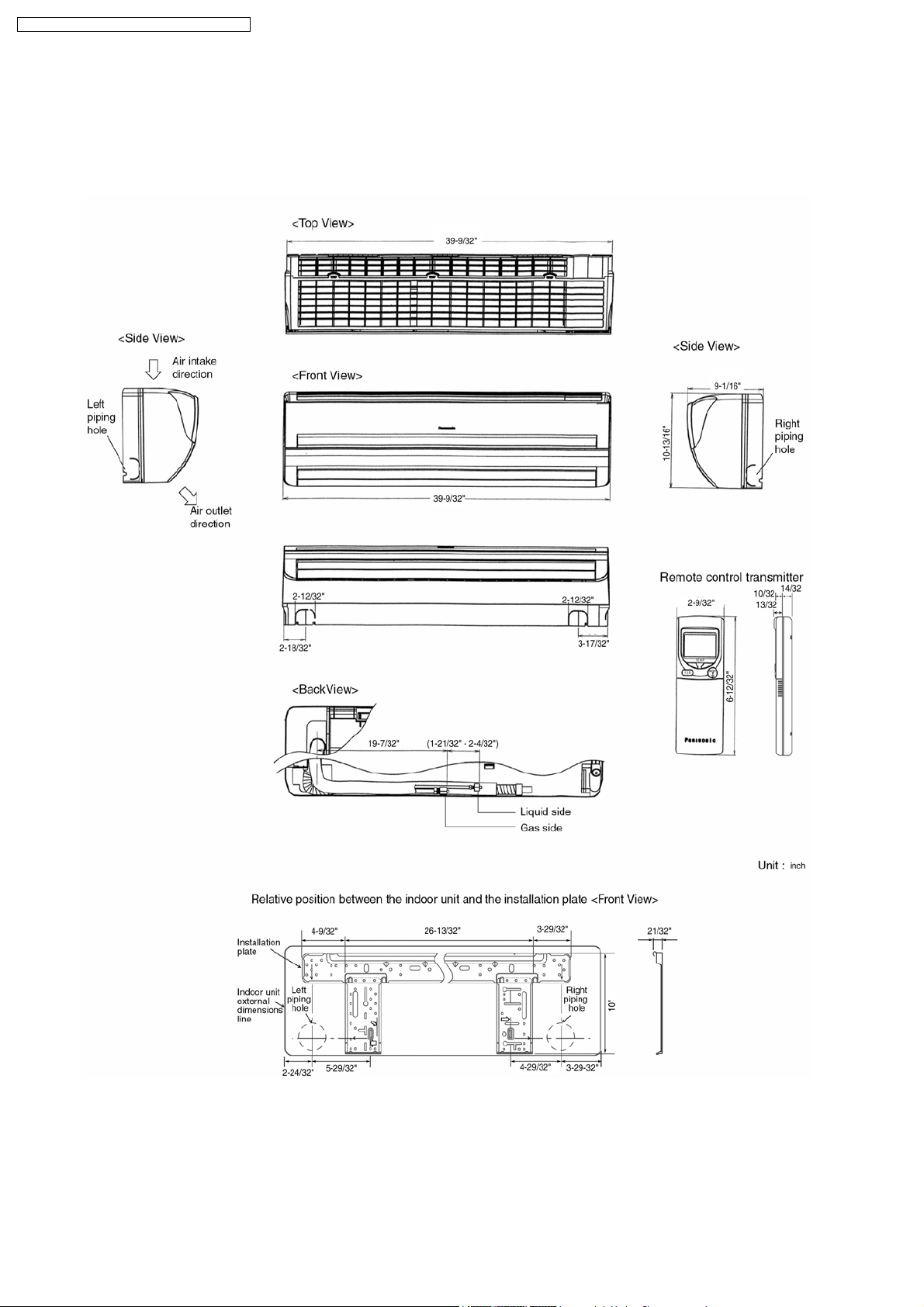
4 Dimensions
4.1. Indoor Unit & Remote Control
4.1.1. CS-C18DKU CS-C24DKU
10
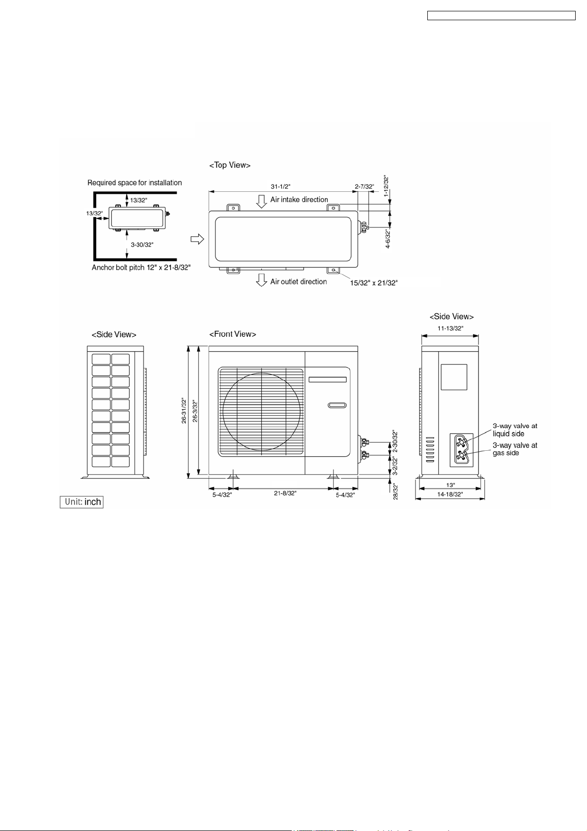
4.2. Outdoor Unit
4.2.1. CU-C18DKU
CS-C18DKU CU-C18DKU / CS-C24D KU CU-C24DKU
11
CS-C18DKU CU-C18DKU / CS-C24D KU CU-C24DKU
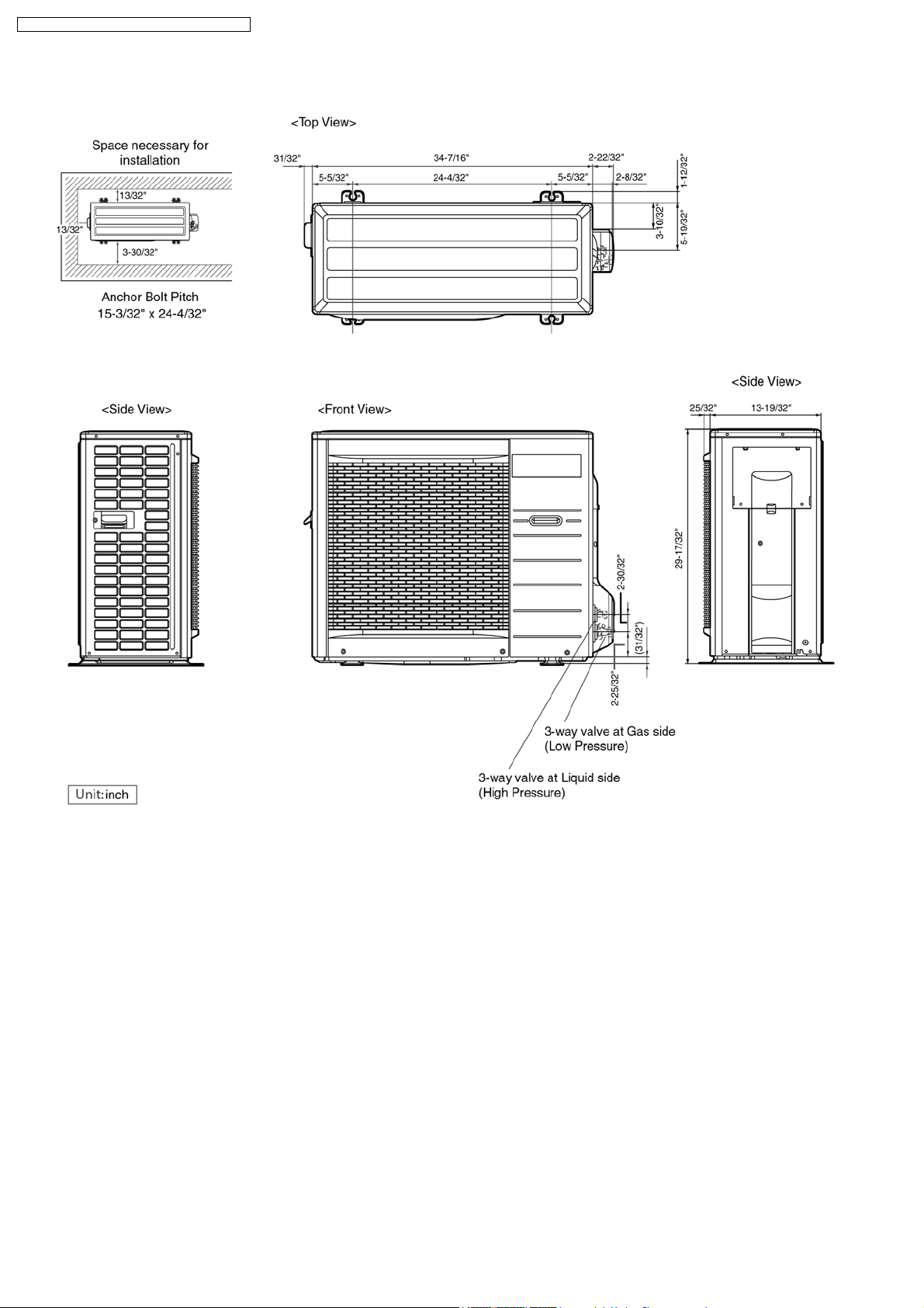
4.2.2. CU-C24DKU
12
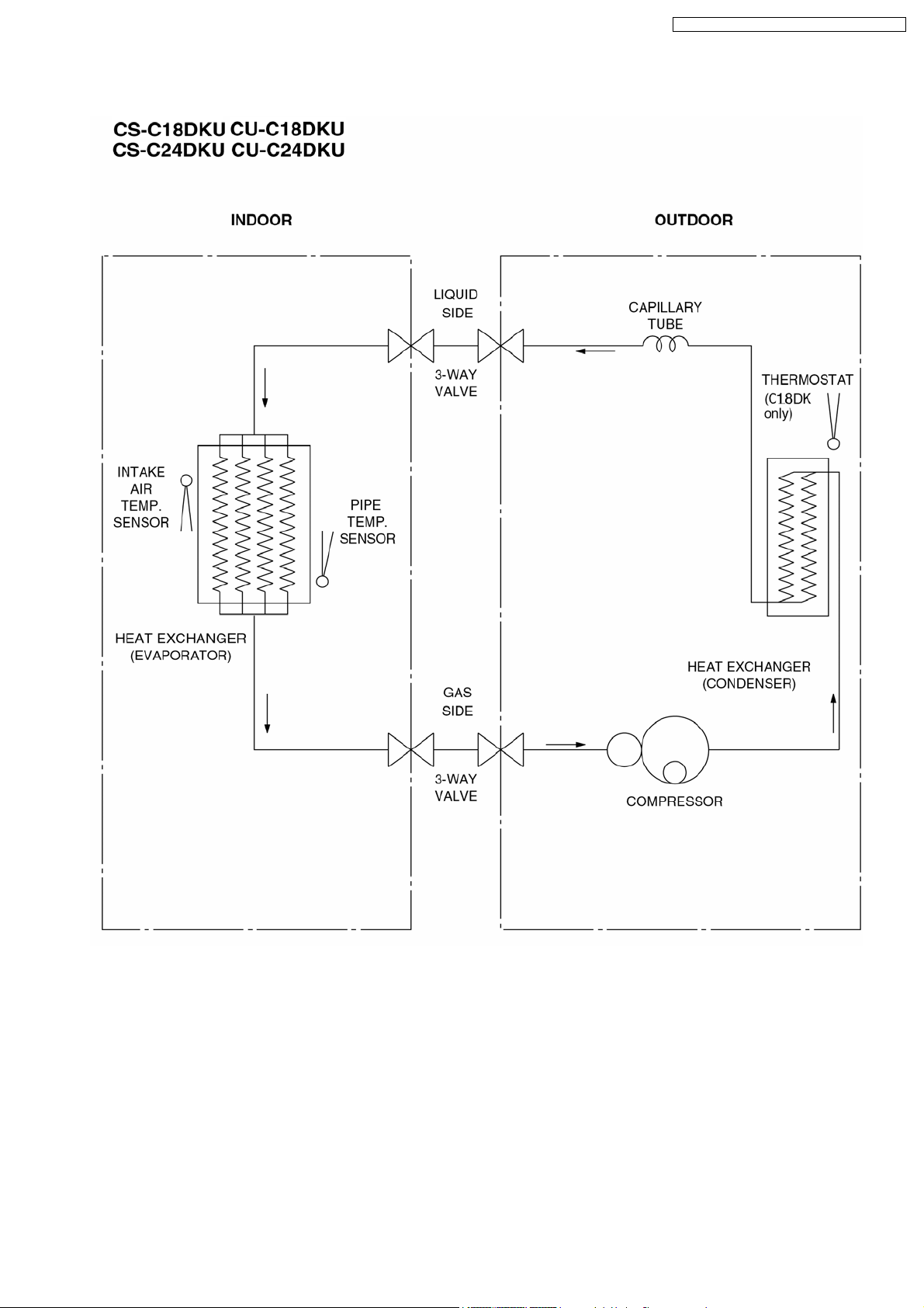
5 Refrigeration Cycle Diagram
CS-C18DKU CU-C18DKU / CS-C24D KU CU-C24DKU
13
CS-C18DKU CU-C18DKU / CS-C24D KU CU-C24DKU
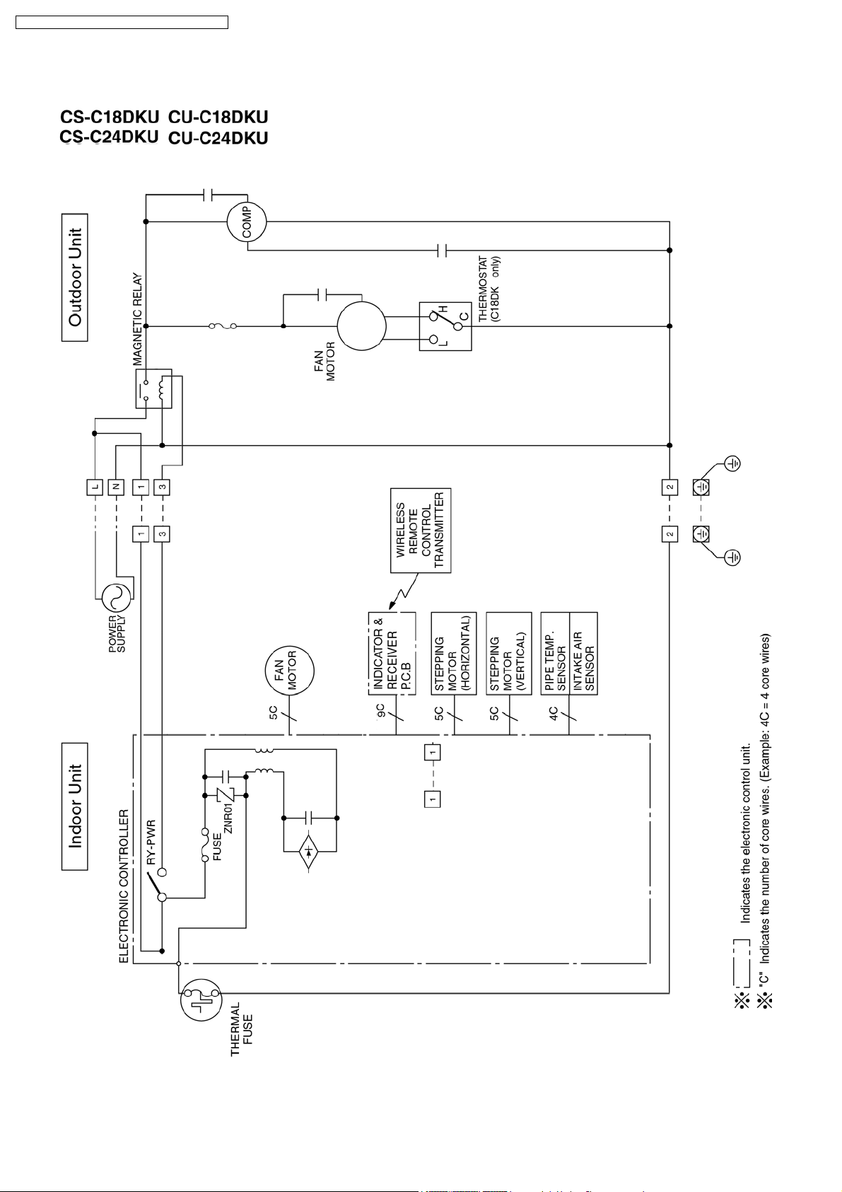
6 Block Diagram
14
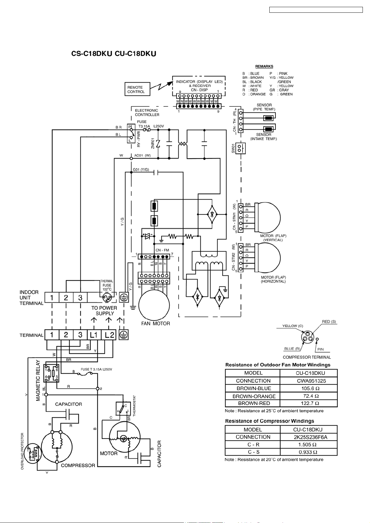
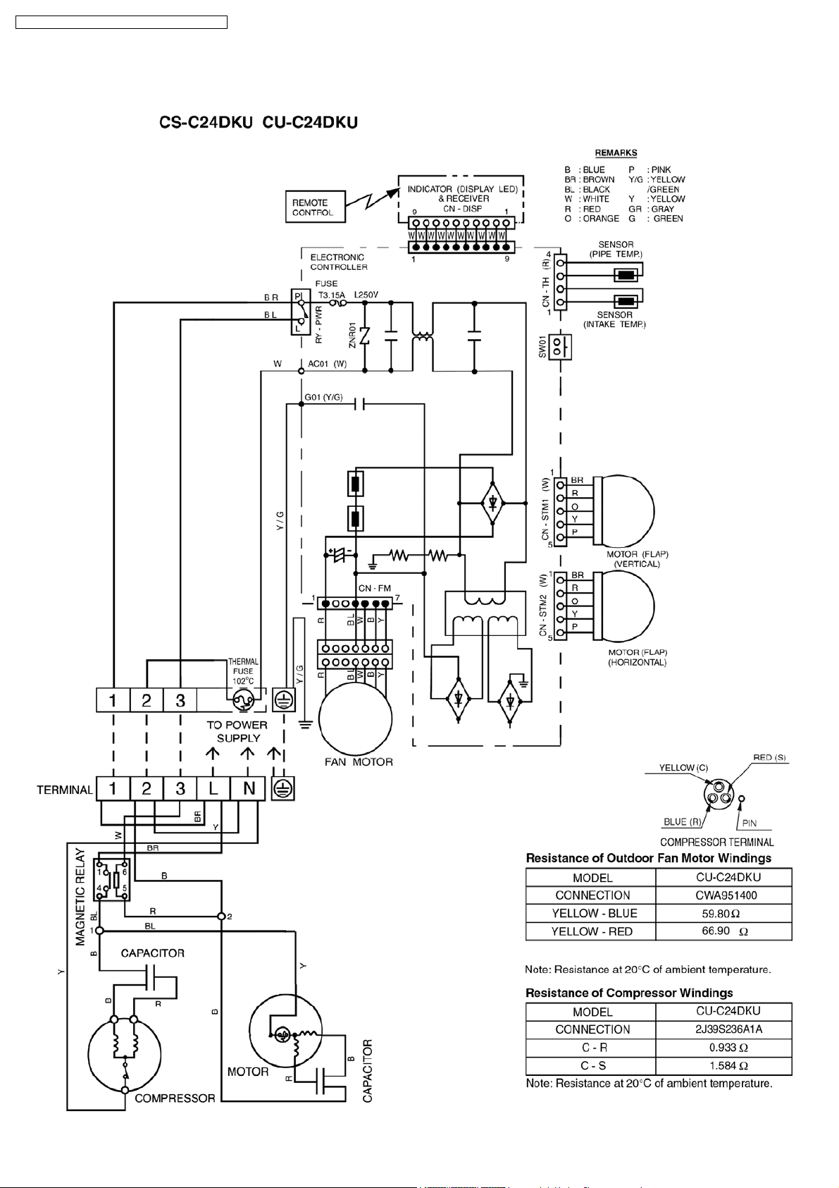
7 Wiring Diagram
CS-C18DKU CU-C18DKU / CS-C24D KU CU-C24DKU
15
CS-C18DKU CU-C18DKU / CS-C24D KU CU-C24DKU
16
CS-C18DKU CU-C18DKU / CS-C24D KU CU-C24DKU
8 Operation Details
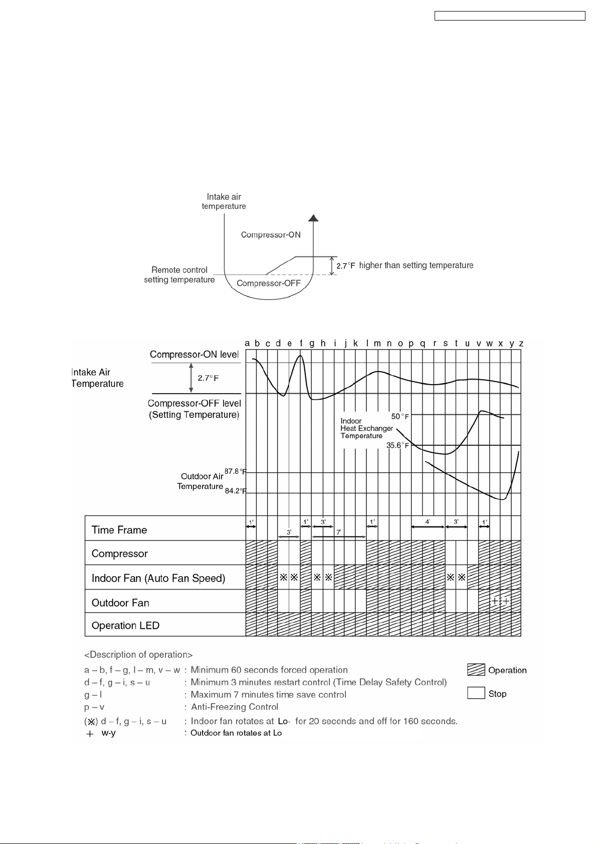
8.1. Cooling Operation
• Cooling operation can be set using remote control.
• This operation is applied to cool down the room temperature reaches the setting temperature set on the remote control.
• The remote control setting temperature, which takes the reading of intake air temperature sensor, can be adjusted from 60°F
to 86°F.
• During cooling operation, the compressor will stop running and restart as shown in below figure.
8.1.1. Cooling Operation Time Diagram
17
CS-C18DKU CU-C18DKU / CS-C24D KU CU-C24DKU
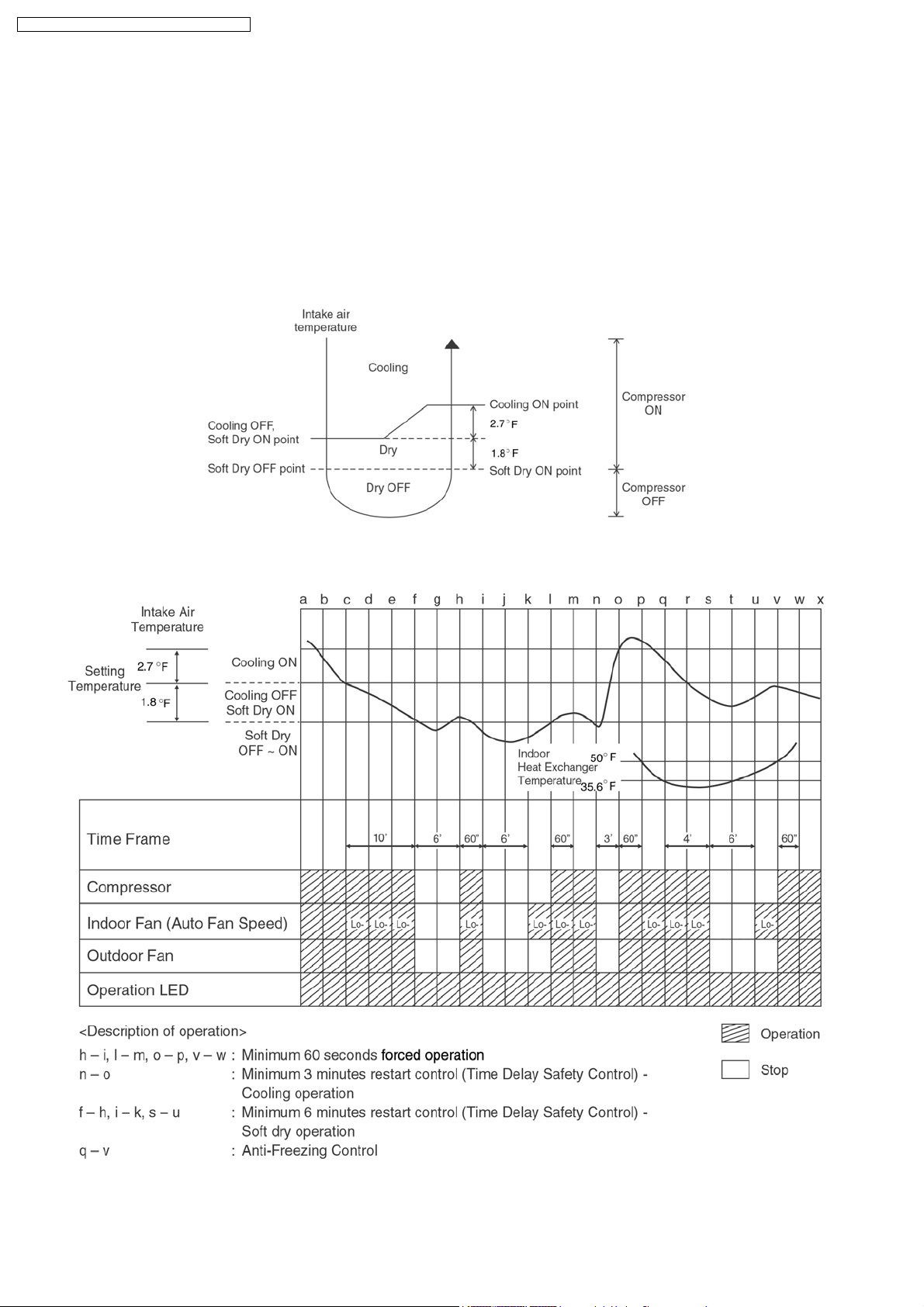
8.2. Soft Dry Operation
• Soft Dry operation can be set using remote control.
• Soft Dry operation is applied to dehumidify and to perform a gentle cooling to the room.
• This operation starts when the intake air temperature sensor reaches the setting temperature on the remote control.
• When operation begins, Soft Dry will be switched “ON” for a maximum 10 minutes, then Soft Dry operation will be turned “OFF”
for a minimum 6 minutes. After that, the Soft Dry operation will be “ON” and “OFF” based on the setting temperature as shown
in below figure.
• However after 3 minutes of compressor off, during Soft Dry “OFF” (within 6 minutes Soft Dry restart control), the indoor unit will
start to operate at normal Cooling mode if the intake temperature is higher than Cooling “ON” point.
8.2.1. Soft Dry Operation Time Diagram
18
CS-C18DKU CU-C18DKU / CS-C24D KU CU-C24DKU
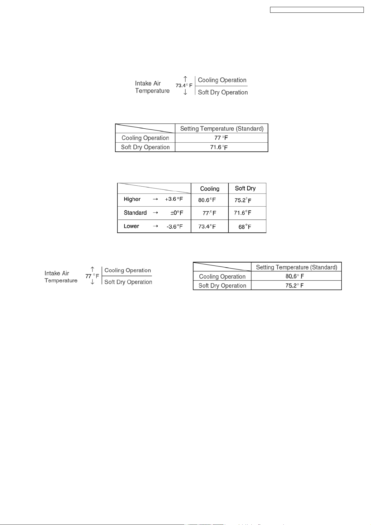
8.3. Automatic Operation
• Automatic operation can be set using remote control.
• This operation starts to operate with indoor fan at SLo speed for 20 seconds to judge the intake air temperature.
• After judged the temperature, the operation mode is determined by refering to the below standard.
• Then, the unit start to operate at determined operation mode, until it is switched off using remote control, with the setting
temperature as shown in below table.
• The setting temperature for all the operations can be changed one level up or one level down from the standard temperature
as shown in below table by pressing on the temperature up or temperature down button at remote control.
• The operation mode judging temperature and standard setting temperature can be increased by 3.6°F permanently, by open
the circuit of JX1 at indoor electronic controller.
19
CS-C18DKU CU-C18 DKU / CS-C24DKU CU-C24DKU
8.4. Operation Control
(For 8.4.1. to 8.4.6. information applies only to Cooling and Soft Dry Operation)
8.4.1. Restart Control (Time Delay Safety Control)
• When the thermo-off temperature (temperature which compressor stops to operate) is reached during:-
− Cooling operation - the compressor stops for 3 minutes (minimum) before resume operation.
− Soft Dry operation - the compressor stops for 6 minutes (minimum) before resume operation.
• If the operation is stopped by the remote control, the compressor will not turn on within 3 minutes from the moment operation
stop, although the unit is turn on again within the period.
• This phenomenon is to balance the pressure inside the refrigerant cycle.
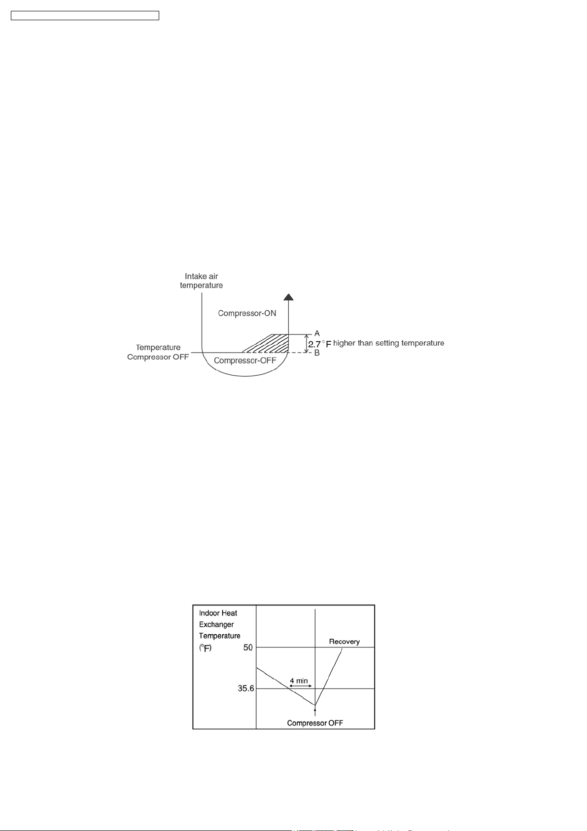
8.4.2. 7 Minutes Time Save Control
• The compressor will start automatically if it has stopped for 7 minutes and the intake air temperature falls between the
compressor ON temperature (A) and compressor OFF temperature (B) during the period.
• This phenomenon is to reduce the built up humidity inside a room.
8.4.3. 60 Seconds Forced Operation
• Once the air conditioner is turned on, the compressor will not stop within 60 seconds in a normal operation although the intake
air temperature has reached the thermo-off temperature. However, force stop by pressing the OFF/ON operation button at the
remote control is permitted.
• The reason for the compressor to force operate at minimum 60 seconds is to allow the refrigerant oil run in a full cycle and
return back to the outdoor unit.
8.4.4. Anti-Freezing Control
• If the temperature of the indoor heat exchanger falls below 35.6°F continuously for 4 minutes or more, the compressor turns off.
The fan speed setting remains the same.
• This phenomenon is to protect the indoor heat exchanger from freezing and to prevent higher volume of refrigerant in liquid form
returning to the compressor.
• Compressor will restart again when the indoor heat exchanger temperature rises to 50°F (Recovery).
• Restart control (Time Delay Safety Control) will be applied in this Control if the recovery time is too short.
20
CS-C18DKU CU-C18 DKU / CS-C24DKU CU-C24DKU
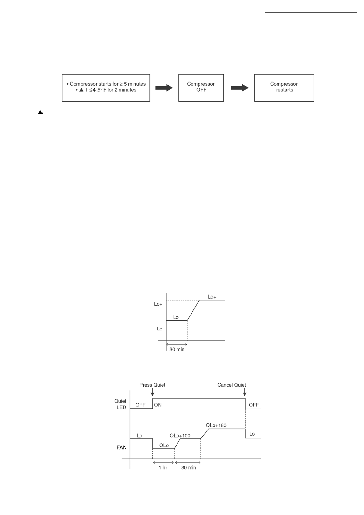
8.4.5. Compressor Reverse Rotation Protection Control
• If the compressor is operating continuously for 5 minutes or longer and the temperature difference between intake air and
indoor heat exchanger is 4.5°F or less for continuous 2 minutes, compressor will stop and restart automatically.
• Time Delay Safety Control is activated before the compressor restart.
T = Intake air temperature - Indoor heat exchanger temperature
• This is to prevent compressor from rotate reversely when there is an instantaneous power failure.
8.4.6. Starting Current Control
• When the compressor, outdoor fan motor and indoor fan motor are simultaneously started, the indoor fan motor will start to
operate at 1.6 second later.
• The reason of the difference is to reduce the starting current flow.
8.4.7. Anti-Dew Formation Control
• Purpose is to prevent dew formation on indoor unit air discharge area.
• When room temperature is constant (±1.8°F) the following conditions occur for 30 minutes continuously, anti-dew formation will
activate:
− Remote Control setting temperature is less than 77°F.
− Compressor is on.
− Cooling operation mode.
− Indoor Fan motor operate at Low fan speed or QLo.
• This control is cancelled immediately when above condition is changed.
• Anti-Dew formation is control by:
1. Increasing Air Flow Volume
a. Lo fan speed
Lo fan speed is changed to Lo+ after 30 min to prevent dew formation.
b. QLo fan speed
Dew formation may occurs at QLo cool, therefore QLo cool is operated only 1 hr 30 min (1 hr QLo, 30 min QLo +100
rpm). After that, it operates at QLo +180rpm (However Quiet LED remains on).
21
CS-C18DKU CU-C18 DKU / CS-C24DKU CU-C24DKU
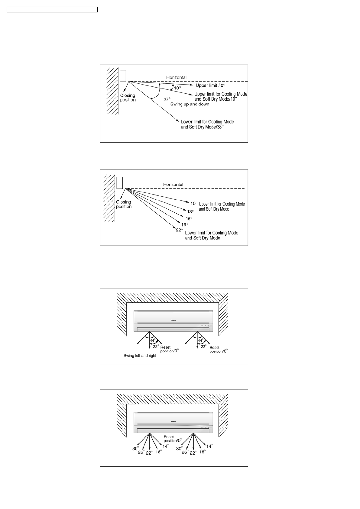
2. Norrowing
Vertical Airflow Direction
− During Anti-dew condensation prevention, Airflow Direction Auto-control angle change from 10° - 38° to 10° - 27° under
Cooling and Soft Dry operation mode.
− During Anti-dew condensation prevention, Airflow Direction Manual control angle change from 10°, 14°, 18°, 22°, 27° to
10°, 13°, 16°, 19°, 22° under Cooling and Soft Dry operation mode.
3. Narrowing
Horizontal Airflow Direction
− During Anti-dew condensation prevention, Airflow Direction Auto-control angle change from 0° - 44° to 14° - 30° under
Cooling and Soft Dry operation mode.
− During Anti-dew condensation prevention, Airflow Direction Manual control angle change from 0°, 11°, 22°, 33°, 44° to
14°, 18°, 22°, 26°, 30° under Cooling and Soft Dry operation mode.
22
CS-C18DKU CU-C18 DKU / CS-C24DKU CU-C24DKU
8.5. Indoor Fan Speed Control
• Indoor Fan Speed can be set using remote control.
8.5.1. Fan Speed Rotation Chart
COOL/ DRY CS-C24DKU CS-C18DKU
SHi 1620 1420
Hi 1570 1360
Me 1450 1250
Lo+ 1360 1220
Lo 1260 1150
Lo- 1100 980
SLo 860 780
QHi 1470 1260
QMe 1350 1150
QLo 1160 1050
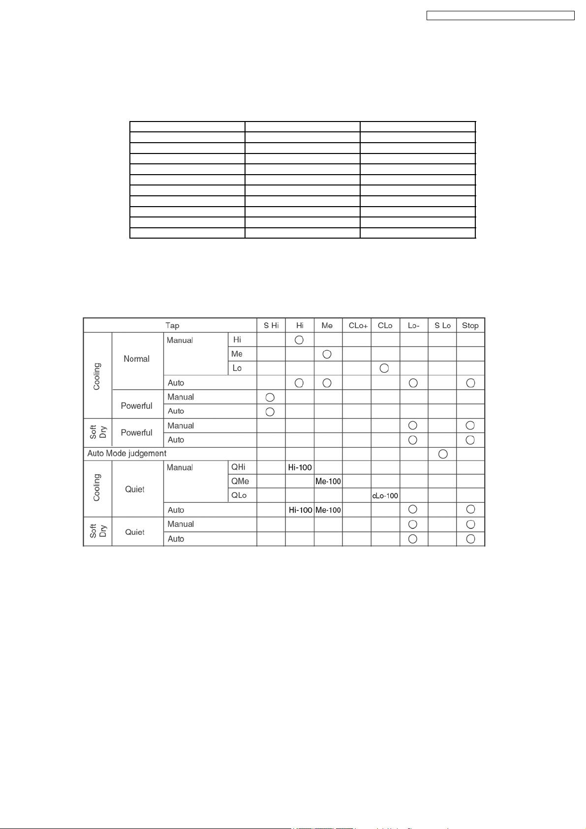
8.5.2. Automatic Fan Speed Control
• When set to Auto Fan Speed, the fan speed is adjusted between maximum and minimum setting as shown in the table.
− Fan speed rotates in the range of Hi, Me and Lo-.
− Deodorizing Control will be activated.
• Auto Fan Speed during Cooling operation:
1. Indoor fan will rotate alternately between off and on as shown in below diagram.
2. At the beginning of each compressor start operation, indoor fan will increase fan speed gradually for deodorizing purpose.
3. For the first time the compressor operate, indoor fan will be switched to Hi fan speed from Lo- after 70 seconds from the
start of compressor. This cause the room temperture to achieve the setting temperature quickly.
4. During compressor stop, indoor fan will operate at Lo- for the beginning 20 seconds to prevent higher volume of refrigerant
in liquid form returning to the compressor.
5. After the compressor at turn off condition for 3 minutes, indoor fan will start to operate at Lo- to circulate the air in the room.
This is to obtain the actual reading of the intake air temperature.
6. For the resume of compressor operation, indoor fan will operate at Me fan speed to provide comfort and lesser noise
environment, after 70 seconds from the restart of compressor.
23
 Loading...