

Panasonic CS-A120TE, CU-A120TE, CS-A240TE, CU-A240TE, CS-A180TE Service Manual
...
ORDER NO. MAC9710021C2
Service Manual
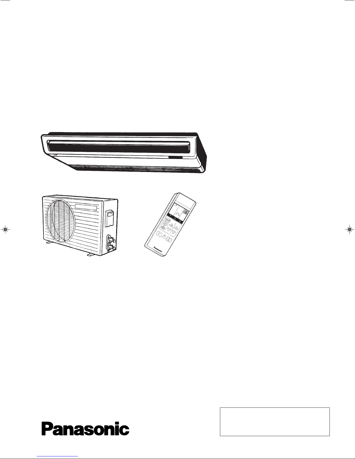
Room Air Conditioners
CS-A120TE / CU-A120TE
CS-A180TE / CU-A180TE
CS-A240TE / CU-A240TE
Contents
● Functions ...........................................................1 ~ 2
● Product Specifications .......................................3 ~ 8
● Dimensions ......................................................9 ~ 10
● Refrigeration Cycle Diagram..................................11
● Block Diagram ................................................12~ 13
● Wiring Diagram ..............................................14 ~ 15
● Operation Details ...........................................16 ~ 18
● Servicing Information .............................................19
● Troubleshooting Guide ..................................20 ~ 21
● Technical Data.......................................................22
● Exploded View .................................................23, 25
● Replacement Parts List....................................24, 26
● Electronic Parts List ...............................................27
1997 Matsushita Industrial Corp. Sdn. Bhd.
(11969-T)
All rights reserved. Unauthorized copying and distribution is a violation of law.
!
WARNING
This service information is designed for experienced repair technicians only and is not designed for use by the general public. It does not contain
warnings or cautions to advise non-technical individuals of potential dangers in attempting to service a product. Products powered by electricity
should be serviced or repaired only by experienced professional technicians. Any attempt to service or repair the product or products dealt with
in this service information by anyone else could result in serious injury or death.
!
PRECAUTION OF LOW TEMPERATURE
In order to avoid frostbite, be assured of no refrigerant leakage during the installation or repairing of refrigeration circuit.
CS-A120TE
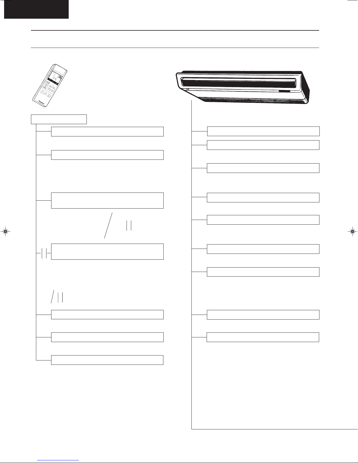
Functions
Remote-control Transmitter Indoor Unit
Remote Control
Operation START/STOP
s d f #
Operation Mode Selection
s Automatic Operation Mode
d Cooling Operation Mode
f Soft Dry Operation Mode
# Heating Operation Mode
Indoor Fan Speed Selection / Time
Setting
High Speed
h
Medium Speed
j
Low Speed
k
Room Temperature Setting / Time
e
Setting
r
● Temperature Setting (20°C to 30°C)
● o(higher), n (standard), m (lower)
...Automatic Operation
.... up to 12
e
.... up to 1
r
t/x
Timer Operation Selection
.... up to 12
e
.... up to 1
r
Power Switch OFF/ON
Sensing The Room Temperature
● Room Temperature Sensor (thermistor)
Starting Current Control
● Indoor Fan is delayed for 1.6 seconds at the
starting
Time Delay Safety Control
● Restarting is inhibited for apporox. 3 minutes
Circuit Protection Control
● 30 seconds forced operation of the compres-
sor
Indoor Fan Speed Control
● High, Med, Low
Operation Indication Lamps (LED)
(green) ......Lights up in operation
q
(red) ..........Automatic Airflow Direction in
c
operation
b
(orange) ....Timer in operation
Soft Dry Operation Mode
● ON/OFF Dual Timer Setting
SET/C
Timer Operation Set/Cancel
● Set/Cancel the selected Timer Operation
Airflow Direction Control
vv
v ● Airflow Direction Manual Control
vv
cc
c ● Automatic Airflow Direction Control
cc
● Intermittent operation of Fan at low speed
Room Temperature Control
● Maintains the room temperature accordance
with the Setting Temp.
– 1 –

Functions
CS-A120TE
Outdoor Unit
Hot-start Control (Heating)
● The indoor fan stops until the Evaporator
piping temperature will be reached.
Automatic Restarting Control
● 7 minutes automatic restarting at Cooling,
Soft Dry operation
Sleep Mode Auto Control
● The Fan is switched to Low fan speed and the
unit will be stopped after 5 hours
● The setting temperature will be raised by 1°C
at the starting and by 1°C one hour later (Soft
Dry of Cooling Operation)
● The setting temperature will be dropped by
2°C at the starting and by 3°C one hour later
(Heating operation).
Deice (defrost) Control
● Both the indoor and outdoor fan stops during
deicing
● Hot start after deice ends
● Starts operation when indoor piping
temperature drops below temperature setting
60 ± 10 minutes after heating start or deice
ends
● Operations LED flashes.
Overload Protection
● Thermostat OFF if the Piping temperature
exceeds 100°C
Automatic Operation Determination
● Selects cooling, dry or heating with the indoor
intake sensor
25°C or higher.....cooling
21 to 24°C ........... dry
20°C or lower ......heating
● 5-minutes automatic restarting is activated
instead of 7-minutes
Overload Protection
30sec. Forced Operation Control
● Once the compressor is activated it does not
stop for 30 secs
● Stops immediately with remote control stop
Anti-freezing Control For The
Evaporator
● Compressor will be stopped when the
Evaporator’s piping temperature is 0°C or
less for three minutes
● Restarting at 12°C or higher (Time Delay
Safety Control has a priority)
Airflow Direction Control
Automatic Airflow Direction Control
● The louver automatically swings up and down
(Cooling, Soft Dry)…horizontal and 30°
downward
● The louver is set at 60° downward during
Heating Operation
● The louver is set at horizontal when the fan is
stopped
Airflow Direction Manual Control
● Can be set within a range at horizontal to 60°
downward
– 2 –

CS-A120TE
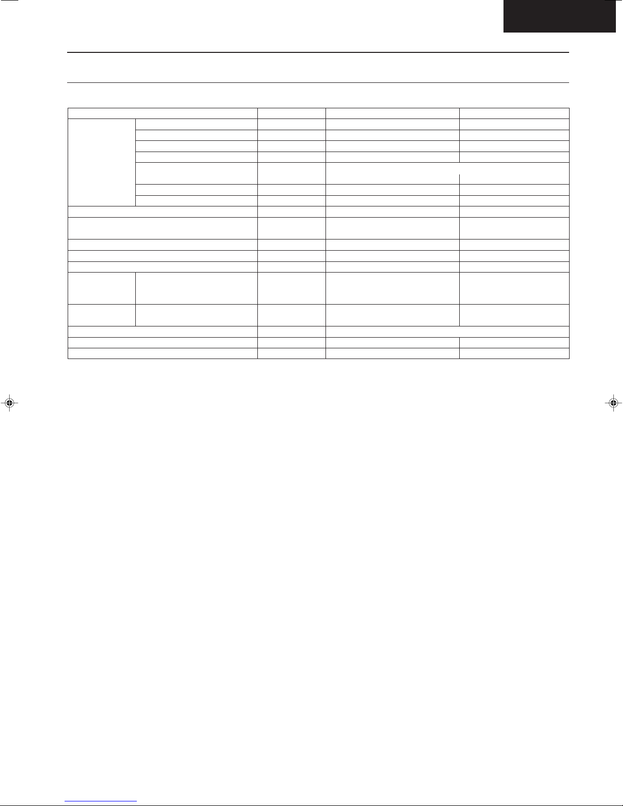
Product Specifications
Cooling Capacity
Heating Capacity
Moisture Removal
Power Source
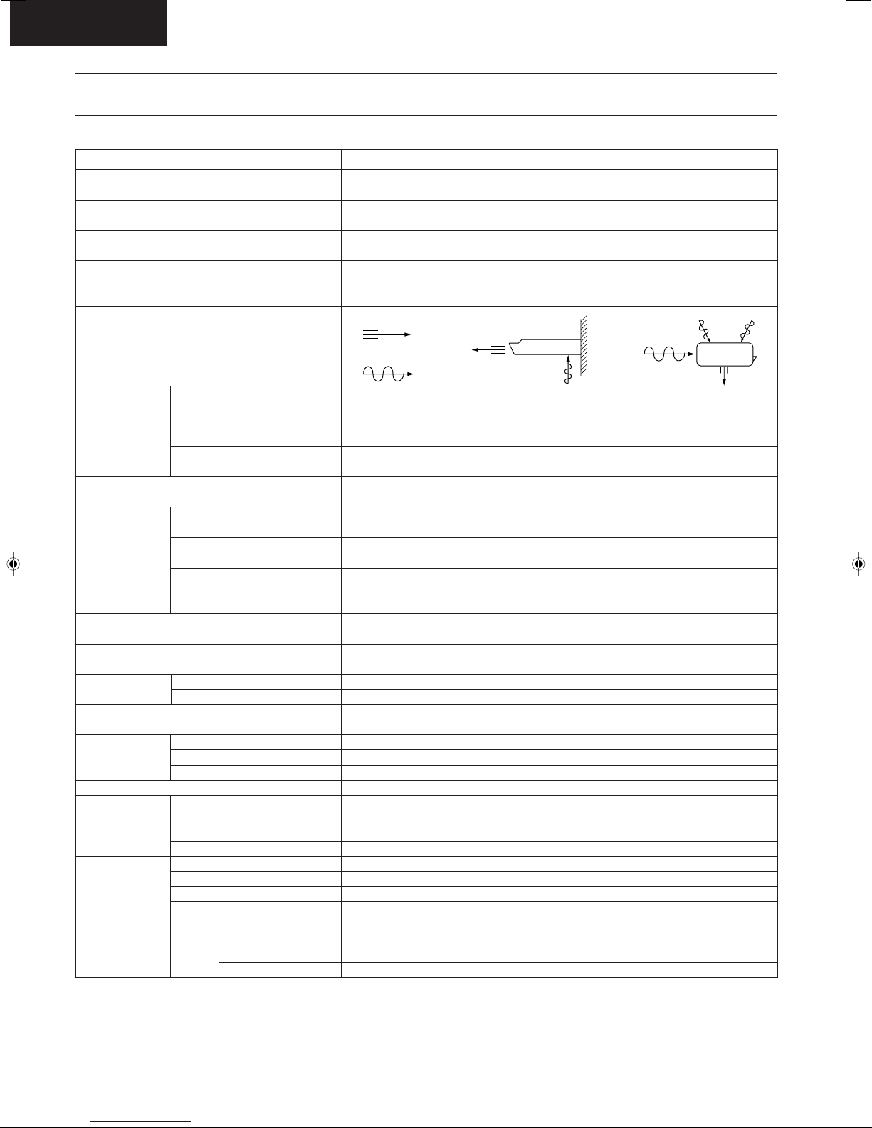
Airflow Method
Air Volume
Noise Level
Electrical
Data
Piping Connection Port
(Flare piping)
Pipe Size
(Flare piping)
Drain
Hose
Power Cord Length
Dimensions
Net Weight
Compressor
Air Circulation
Indoor Air (Lo)
Indoor Air (Me)
Indoor Air (Hi)
Input
Running Current
COP
Starting Current
Inner diameter
Length
Number of core-wire
Motor Type
Rated Output
Motor Type
Fan Low
Speed Medium
Height
Width
Depth
Type
Type
Material
Input
Rated Output
High
Unit
kW
Btu/h
kW
Btu/h
s/h
Pint/h
Phase
V
Cycle
OUTLET
INTAKE
3
m
/min (cfm)
3
/min (cfm)
m
m3/min (cfm)
dB (A)
kW
A
W/W
A
inch
inch
inch
inch
mm
m
m
inch (mm)
inch (mm)
inch (mm)
lb (kg)
W
W
W
rpm
rpm
rpm
CS-A120TE
3.40 - 3.35
11,600 - 11,400
4.10 - 4.00
13,900 - 13,600
2.0
4.2
Single
240 - 220
50
SIDE VIEW
8.9 (314)
9.6 (339)
10.0 (350)
Cooling ; High 46/45, Low 42/41
Heating ; High 46/45, Low 42/41
Cooling ; 1.30 - 1.27
Heating ; 1.35 - 1.27
Cooling ; 5.8 - 6.0
Heating ; 6.1 - 6.0
Cooling ; 2.6 - 2.6
Heating ; 3.0 - 3.1
25
G ; Half Union 1/2"
L ; Half Union 1/4"
G (gas side) ; 1/2"
L (liquid side) ; 1/4"
20
2
2.3
62 (28)
–
–
–
45.6
20
980
1,055
1,100
2
)
3 (1.0mm
6-1/2 (165)
43-5/16 (1,100)
25-19/32 (650)
SIROCCO
STYLAC 181
Induction (4-pole)
CU-A120TE
TOP VIEW
–
–
–
Cooling ; High 47/46
Heating ; High 47/46
G ; 3-way valve 1/2"
L ; 2-way valve 1/4"
G (gas side) ; 1/2"
L (liquid side) ; 1/4"
–
–
–
–
19-29/32 (505)
30-23/32 (780)
9-21/32 (245)
89 (40)
Rotary (1 cylinder)
rolling piston type
Induction (2-pole)
1,100
Propeller Fan
AES + Glass Fiber 12%
Induction (6-pole)
58.6
20
–
–
730
– 3 –
Product Specifications
CS-A120TE
Unit
Heat
Exchanger
Refrigerant Control Device
Refrigeration Oil
Refrigerant (R-22)
Thermostat
Protection Device
Capillary Tube
Air Filter
Capacity Control
Compressor Capacitor
Fan Motor Capacitor
• Specifications are subject to change without notice for further improvement.
Description
Tube material
Fin material
Fin Type
Row / Stage
FPI
Size (W × H × L)
Length
Flow Rate
Inner Diameter
Material
Style
mm
(c.c)
g (oz)
mm
s/min
mm
µF, VAC
µF, VAC
CS-A120TE
Evaporator
Copper
Aluminium
Louver Fin
(Plate fin configuration, forced draft)
1 × 10
21
900 × 254 × 22
–
–
–
Electronic Control
–
–
–
–
P.P.
Honeycomb
Capillary Tube
–
1.2 µF, 400VAC
Cooling ; 625, Heating ; 720
Cooling ; 13.5, Heating ; 11.0
Cooling ; 1.6, Heating ; 1.5
CU-A120TE
Condenser
Copper
Aluminium
Corrugated Fin
2 × 19
16
706 × 482 × 44
Capillary Tube
SUNISO 4GDID or
ATMOS M60 (410)
1,090 (38.5)
–
Overloaded Protector
–
30 µF, 370VAC
1.2 µF, 400VAC
– 4 –
CS-A120TE
Product Specifications
Cooling Capacity
Heating Capacity
Moisture Removal
Power Source
Airflow Method
Air Volume
Noise Level
Electrical
Data
Piping Connection Port
(Flare piping)
Pipe Size
(Flare piping)
Drain
Hose
Power Cord Length
Dimensions
Net Weight
Compressor
Air Circulation
Indoor Air (Lo)
Indoor Air (Me)
Indoor Air (Hi)
Input
Running Current
COP
Starting Current
Inner diameter
Length
Number of core-wire
Motor Type
Rated Output
Motor Type
Fan Low
Speed Medium
Height
Width
Depth
Type
Type
Material
Input
Rated Output
High
Unit
kW
Btu/h
kW
Btu/h
s/h
Pint/h
Phase
V
Cycle
OUTLET
INTAKE
3
m
/min (cfm)
3
/min (cfm)
m
m3/min (cfm)
dB (A)
kW
A
W/W
A
inch
inch
inch
inch
mm
m
m
inch (mm)
inch (mm)
inch (mm)
lb (kg)
W
W
W
rpm
rpm
rpm
CS-A180TE
5.10 - 5.05
17,400 - 17,200
5.45 - 5.35
18,600 - 18,200
2.8
5.9
Single
240 - 220
50
SIDE VIEW
10.0 (354)
10.7 (379)
11.5 (400)
Cooling ; High 51/50, Low 46/44
Heating ; High 52/51, Low 46/45
Cooling ; 2.19 - 2.08
Heating ; 2.04 - 1.90
Cooling ; 10.7 - 10.3
Heating ; 9.9 - 9.4
Cooling ; 2.3 - 2.4
Heating ; 2.7 - 2.8
52
G ; Half Union 1/2"
L ; Half Union 1/4"
G (gas side) ; 1/2"
L (liquid side) ; 1/4"
20
2
2.3
2
3 (1.5mm
6-1/2 (165)
43-5/16 (1,100)
25-19/32 (650)
66 (30)
SIROCCO
STYLAC 181
Induction (4-pole)
)
–
–
–
67.7
40
1,170
1,250
1,340
CU-A180TE
TOP VIEW
–
–
–
Cooling ; High 56/53
Heating ; High 57/55
G ; 3-way valve 1/2"
L ; 2-way valve 1/4"
G (gas side) ; 1/2"
L (liquid side) ; 1/4"
–
–
–
–
26-31/32 (685)
31-1/2 (800)
11-13/16 (300)
133 (60)
Rotary (1 cylinder)
rolling piston type
Induction (2-pole)
1,700
Propeller Fan
CE10G15 JSR
Induction (4-pole)
120.5 (High)
65
545
–
880
– 5 –

Product Specifications
CS-A120TE
Unit
Heat
Exchanger
Refrigerant Control Device
Refrigeration Oil
Refrigerant (R-22)
Thermostat
Protection Device
Capillary Tube
Air Filter
Capacity Control
Compressor Capacitor
Fan Motor Capacitor
• Specifications are subject to change without notice for further improvement.
Description
Tube material
Fin material
Fin Type
Row / Stage
FPI
Size (W × H × L)
Length
Flow Rate
Inner Diameter
Material
Style
mm
(c.c)
g (oz)
mm
s/min
mm
µF, VAC
µF, VAC
CS-A180TE
Evaporator
Copper
Aluminium
Louver Fin
(Plate fin configuration, forced draft)
2 × 10
20
900 × 254 × 44
–
–
–
Electronic Control
–
–
–
–
P.P.
Honeycomb
Capillary Tube
–
1.2 µF, 450VAC
CU-A180TE
Condenser
Copper
Aluminium
Corrugated Fin
2 × 26
14
769 × 660 × 44
Capillary Tube
SUNISO 4GDID or
ATMOS M60 (700)
1,550 (400)
–
Inner Protector
1,170
21.1
2.4
–
35 µF, 370VAC
3.5 µF, 400VAC
– 6 –

CS-A120TE
Product Specifications
Cooling Capacity
Heating Capacity
Moisture Removal
Power Source
Airflow Method
Air Volume
Noise Level
Electrical
Data
Piping Connection Port
(Flare piping)
Pipe Size
(Flare piping)
Drain
Hose
Power Cord Length
Dimensions
Net Weight
Compressor
Air Circulation
Indoor Air (Lo)
Indoor Air (Me)
Indoor Air (Hi)
Input
Running Current
COP
Starting Current
Inner diameter
Length
Number of core-wire
Motor Type
Rated Output
Motor Type
Fan Low
Speed Medium
Height
Width
Depth
Type
Type
Material
Input
Rated Output
High
Unit
kW
Btu/h
kW
Btu/h
s/h
Pint/h
Phase
V
Cycle
OUTLET
INTAKE
3
m
/min (cfm)
3
/min (cfm)
m
m3/min (cfm)
dB (A)
kW
A
W/W
A
inch
inch
inch
inch
mm
m
m
inch (mm)
inch (mm)
inch (mm)
lb (kg)
W
W
W
rpm
rpm
rpm
CS-A240TE
6.10 - 6.00
20,800 - 20,400
6.20 - 6.00
21,100 - 20,400
3.4
7.2
Single
240 - 220
50
SIDE VIEW
10.5 (370)
11.2 (395)
12.0 (420)
Cooling ; High 52/51, Low 47/45
Heating ; High 52/51, Low 47/45
Cooling ; 2.89 - 2.75
Heating ; 2.62 - 2.40
Cooling ; 13.6 - 13.3
Heating ; 12.5 - 11.7
Cooling ; 2.1 - 2.2
Heating ; 2.4 - 2.5
59
G ; Half Union 5/8"
L ; Half Union 1/4"
G (gas side) ; 5/8"
L (liquid side) ; 1/4"
20
2
2.3
2
3 (2.5mm
6-1/2 (165)
43-5/16 (1,100)
25-19/32 (650)
66 (30)
SIROCCO
STYLAC 181
Induction (4-pole)
)
–
–
–
67.7
40
1,170
1,250
1,340
CU-A240TE
TOP VIEW
–
–
–
Cooling ; High 59/57
Heating ; High 60/58
G ; 3-way valve 5/8"
L ; 2-way valve 1/4"
G (gas side) ; 5/8"
L (liquid side) ; 1/4"
–
–
–
–
26-31/32 (685)
31-1/2 (800)
11-13/16 (300)
140 (62)
Rotary (1 cylinder)
rolling piston type
Induction (2-pole)
2,200
Propeller Fan
CE10G15 JSR
Induction (4-pole)
141.7 (High)
80
620
–
985
– 7 –
 Loading...