

Page 1
Order No. MAC0112088C0
Room Air Conditioner
CS-A12ATP5 CU-A12ATP5
CS-A18ATP5 CU-A18ATPT5
CS-A24ATP5 CU-A24ATPT5
CONTENTS
Page Page
1 Functions 2
2 Product Specifications
3 Dimensions
4 Refrigeration Cycle Diagram
5 Block Diagram
6 Wiring Diagram
7 Operation Details
8 Operating Instructions
9 Installation Instructions
10 Servicing Information 36
5
11 Troubleshooting Guide
11
12 Technical Data
13 Exploded View
13
14
14 Replaceme nt Parts List
16
15 Exploded View
16 Replaceme nt Parts List
18
21
17 Electronic Parts List
25
18 Electronic Circuit Diagram
© 2001 Matsushita Air-Conditioning Corp. Sdn. Bhd.
(183914D). All rights reserved. Unauthorized copying
and distribution is a violation of law.
37
39
42
43
44
45
46
47
Page 2
CS-A12ATP5 CU-A12ATP5 / CS-A18ATP5 CU-A18ATPT5 / CS-A24ATP5 CU-A24ATPT5
1 Functions
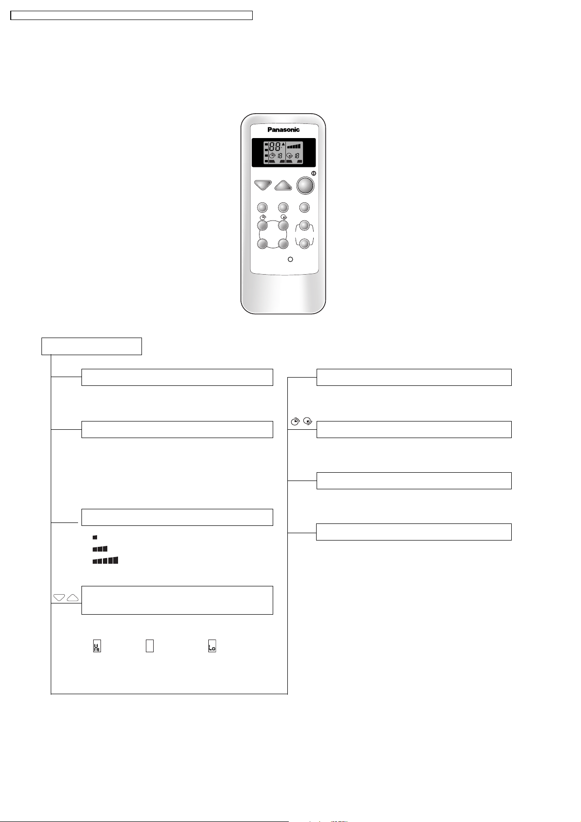
Remote Control Transmitter
Remote Control
Operation START/STOP
AUTO
HEAT
COOL
OFF ON OFF ON
DRY
TEMP
MODE SLEEP
TIMER
OFF/ON SET/C
C
H H
OFF/ON
RESET
SLEEP
FAN
SPEED
FAN SPEED
AUTO
AIR SWING
MANUAL
Sleep Mode Auto-Control
●
Starts/Stops when the button is pressed
Operation Mode Selection
•
AUTO
•
HEAT
COOL
•
•
DRY
Automatic Operation Mode
Heating Operation Mode
Cooling Operation Mode
Soft Dry Operation Mode
Indoor Fan Speed Selection
• Low Fan Speed
• Medium Fan Speed
• High Fan Speed
TEMP
Room Temperature Setting / Time
Setting
●
Temperature Setting (20°C to 30°C)
●
(higher), (standard), (lower)
... Automatic Operation
Timer Operation Selection
●
12 hours ON/OFF Dual Timer Setting
SET/C
Timer Operation Set/Cancel
●
Set/Cancel the selected Timer Operation
Airflow Direction Control
●
Airflow Direction Manual Control
●
Automatic Airflow Direction Control
2
Page 3
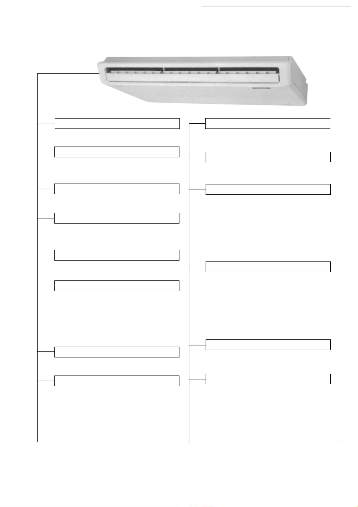
Indoor Unit
CS-A12ATP5 CU-A12ATP5 / CS-A18ATP5 CU-A18ATPT5 / CS-A24ATP5 CU-A24ATPT5
Sensing The Room Temperature
●
Room Temperature Sensor (thermistor)
Starting Current Control
●
Indoor Fan is delayed for 1.6 seconds at the
starting
Time Delay Safety Control
●
Restarting is inhibited for apporox. 3 minutes
Circuit Protection Control
●
30 seconds forced operation of the
compressor
Indoor Fan Speed Control
●
High, Med, Low
Operation Indication Lamps (LED)
●
POWER
(green).........Lights up in operation
●
AIR SWING
●
TIMER
●
SLEEP
(red)......... Automatic Airflow
Direction in operation
(orange) ........ Timer in operation
(orange) ........ Sleep Mode Auto in
operation
Hot-start Control (Heating)
●
The indoor fan stops until the Evaporator
piping temperature will be reached.
Automatic Restarting Control
●
7 minutes automatic restarting at Cooling,
Soft Dry operation.
Sleep Mode Auto Control
●
The Fan is switched to Low fan speed and the
unit will be stopped after 5 hours
●
The setting temperature will be raised by 1°C
at the starting and by 1°C one hour later (Soft
Dry of Cooling Operation)
●
The setting temperature will be dropped by
2°C at the starting and by 3°C one hour later
(Heating Operation)
Deice (defrost) Control
●
Both the indoor and outdoor fan stops
during deicing
●
Hot start after deice ends.
●
Starts operation when indoor piping
temperature drops below temperature
setting 60 ± 10 minutes after heating
start or deice ends
●
Operations LED flashes
Soft Dry Operation Mode
●
Intermittent operation of Fan at low speed
Room Temperature Control
●
Maintains the room temperature accordance
with the Setting Temp.
Overload Protection
●
Thermostat OFF if the Piping
temperature exceeds 100°C
Automatic Operation Determination
●
Select cooling, dry or heating with the
indoor intake sensor
25°C or higher ........... cooling
21 to 24°C .................. dry
20°C or lower ............. heating
●
5-minutes automatic restarting is
activated instead of 7-minutes.
3
Page 4

CS-A12ATP5 CU-A12ATP5 / CS-A18ATP5 CU-A18ATPT5 / CS-A24ATP5 CU-A24ATPT5
Outdoor Unit
Anti-freezing Control For The
Evaporator
●
Compressor will be stopped when the
Evaporator’s piping temperature is 0°C or
less for three minutes
●
Restarting at 12°C or higher (Time Delay
Safety Control has a priority)
Airflow Direction Control
Automatic Airflow Direction Control
●
The louver automatically swings up and down
(Cooling, Soft Dry) ....... horizontal and 30°
downward
●
The louver is set at 60° downward during
Heating Operation
●
The louver is set at horizontal when the fan is
stopped
Airflow Direction Manual Control
●
Can be set within a range at horizontal to 60°
downward
Overload Protector
30 sec. Forced Operation Control
●
Once the compressor is activated it does
not stop for 30 secs
●
Stops immediately with remote control
stop
4
Page 5
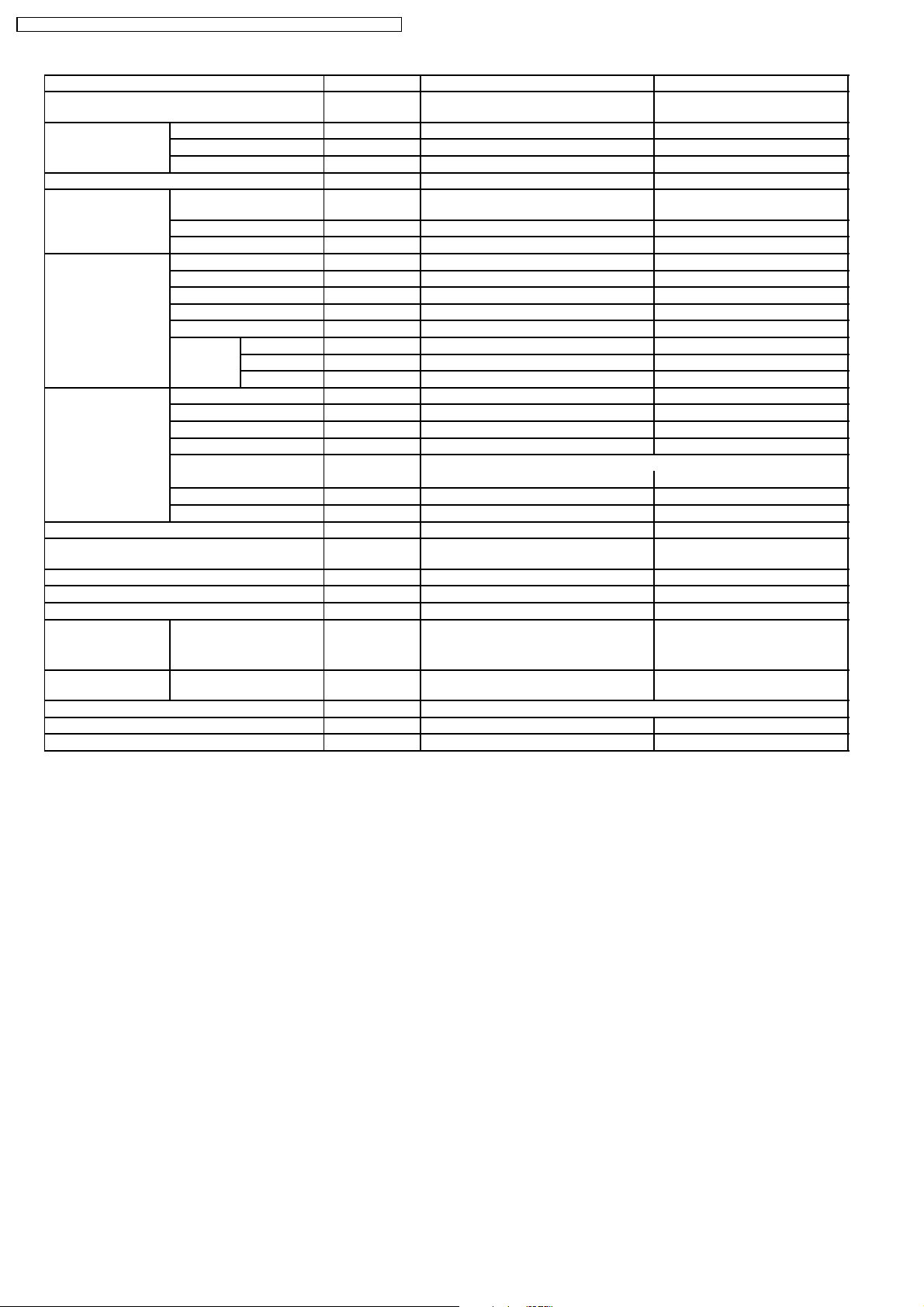
2 Product Specifications
Unit CS-A12ATP5 CU-A12ATP5
CS-A12ATP5 CU-A12ATP5 / CS-A18ATP5 CU-A18ATPT5 / CS-A24ATP5 CU-A24ATPT5
Cooling Capacity kW
Heating Capacity kW
Moisture Removal l/h
Power Source Phase
Airflow Method OUTLET
Air Volume Indoor Air (Lo) m3/min (cfm) 8.9 (314) —
BTU/h
kcal/h
BTU/h
kcal/h
Pint/h
V
Cycle
SIDE VIEW TOP VIEW
INTAKE
3.35; 3.35; 3.40
11,400; 11,400; 11,600
2,870; 2,870; 2,920
4.00; 4.00; 4.10
13,600; 13,600; 13,900
3,430; 3,430; 3,500
2.0
4.2
Single
220; 230; 240
50
Indoor Air (Me) m3/min (cfm) 9.6 (339) —
Indoor Air (Hi) m3/min (cfm) 10.0 (350) —
Noise Level dB (A) Cooling: High 45; 46; 46 Low 41; 42; 42
Power Noise Level dB (A) Cooling: High 59
Electrical Data Input kW Cooling: 1.27; 1.28; 1.30
Running Current A Cooling: 6.0; 5.9; 5.8
EER W/W (BTU/hW) Cooling: 2.64 (9.0); 2.62 (8.9); 2.62 (8.9)
COP W/W (BTU/hW) Heating: 3.15 (10.7); 3.03 (10.3); 3.04 (10.3)
Starting Current A 25
Piping Connection Port
(Flare piping)
Pipe Size
(Flare piping)
Drain
Hose
Inner diameter mm 20 —
Length m 0.6 —
inch
inch
inch
inch
Heating: High 45; 46; 46 Low 41; 42; 42
Heating: High 59
Heating: 1.27; 1.32; 1.35
Heating: 6.0; 6.1; 6.1
G ; Half Union 1/2”
L ; Half Union 1/4”
G (gas side) ; 1/2”
L (liquid side) ; 1/4”
Cooling: High 46; 47; 47
Heating: High 46; 47; 47
Cooling: High 62
Heating: High 62
G ; 3-way valve 1/2”
L ; 2-way valve 1/4”
G (gas side) ; 1/2”
L (liquid side) ; 1/4”
5
Page 6
CS-A12ATP5 CU-A12ATP5 / CS-A18ATP5 CU-A18ATPT5 / CS-A24ATP5 CU-A24ATPT5
Unit CS-A12ATP5 CU-A12ATP5
Power Cord Length
Number of core-wire
m 2.3
3 (1.0 mm
2
)
—
—
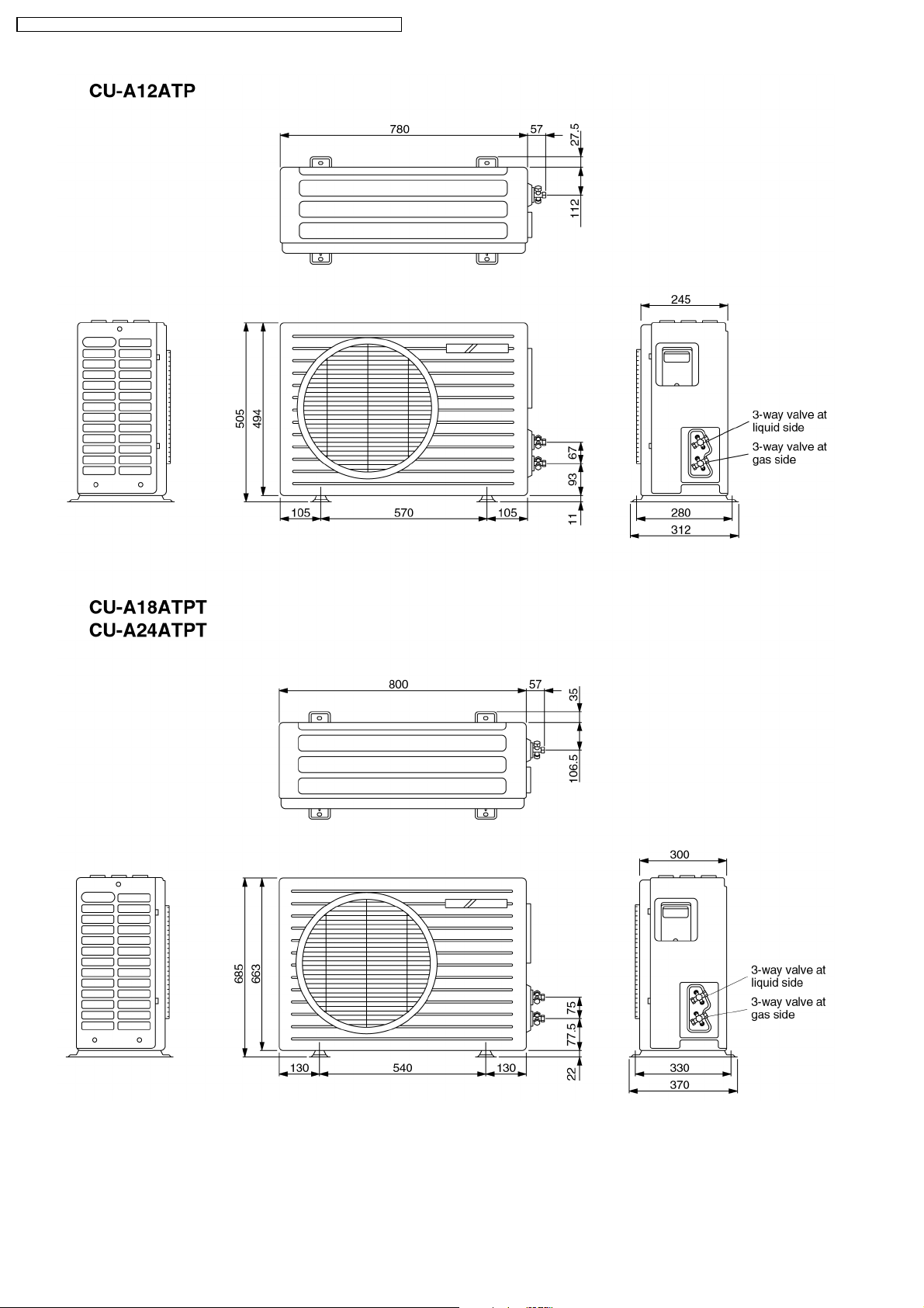
Dimensions Height inch (mm) 6 - 1/2 (165) 19 - 29/32 (505)
Width inch (mm) 43 - 5/16 (1,100) 30 - 23/32 (780)
Depth inch (mm) 25 - 19/32 (650) 9 - 21/32 (245)
Net Weight lb (kg) 62 (28) 88 (40)
Compressor Type — Rotary (1 cylinder)
rolling piston type
Motor Type — Induction (2-poles)
Rated Output W — 1,100
Air Circulation Type SIROCCO Propeller Fan
Material STYLAC 181 AES + Glass Fiber 12%
Motor Type Induction (4-poles) Induction (6-poles)
Input W 45.6 58.6
Rated Output W 20 20
Fan Speed Low rpm 980 —
Medium rpm 1,055 —
High rpm 1,100 730
Heat Exchanger Description Evaporator Condenser
Tube material Copper Copper
Fin material Aluminium Aluminium
Fin Type Louver Fin Corrugated Fin
Row / Stage (Plate fin configuration, forced draft)
1×10 2×19
FPI 21 16
Size (W × H × L) mm 900 × 254 × 22 706 × 482 × 44
Refrigerant Control Device — Capillary Tube
Refrigeration Oil (c.c) — SUNISO 4GDID or ATMOS M60
(410)
Refrigerant (R-22) g (oz.) — 1,090 (38.5)
Thermostat Electronic Control —
Protection Device — Overload Protector
Length mm — Cooling; 625, Heating; 720
Capillary Tube Flow Rate l/min — Cooling; 13.5, Heating; 11.0
Inner Diameter mm — Cooling; 1.6, Heating; 1.5
Air Filter Material
Style
P.P.
Honeycomb
—
Capacity Control Capillary Tube
Compressor Capacitor µF, VAC — 30 µF, 370VAC
Fan Motor Capacitor µF, VAC 1.2 µF, 450VAC 1.2 µF, 400VAC
•
Specifications are subject to change without notice for further improvement.
6
Page 7

CS-A12ATP5 CU-A12ATP5 / CS-A18ATP5 CU-A18ATPT5 / CS-A24ATP5 CU-A24ATPT5
Unit CS-A18ATP5 CU-A18ATPT5
Cooling Capacity kW
BTU/h
kcal/h
Heating Capacity kW
BTU/h
kcal/h
Moisture Removal l/h
Pint/h
Power Source Phase
V
Cycle
Airflow Method OUTLET
SIDE VIEW TOP VIEW
5.05; 5.05; 5.10
17,200; 17,200; 17,400
4,340; 4,340; 4,390
5.35; 5.35; 5.45
18,200; 18,200; 18,600
4,600; 4,600; 4,690
2.8
5.9
Single
220; 230; 240
50
INTAKE
Air Volume Indoor Air (Lo) m3/min (cfm) 10.4 (354) —
Indoor Air (Me) m3/min (cfm) 10.7 (379) —
Indoor Air (Hi) m3/min (cfm) 11.5 (400) —
Noise Level dB (A) Cooling: High 50; 51; 51 Low 44; 46; 46
Heating: High 51; 52; 52 Low 45; 46; 46
Cooling: High 53; 56; 56
Heating: High 56; 57; 57
Power Noise Level dB (A) Cooling: High 64
Heating: High 65
Electrical Data Input kW Cooling: 2.08; 2.13; 2.19
Heating: 1.90; 1.98; 2.04
Running Current A Cooling: 10.3; 10.5; 10.7
Heating: 9.4; 9.7; 9.9
EER W/W (BTU/hW) Cooling: 2.43 (8.3); 2.37 (8.1); 2.33 (7.9)
COP W/W (BTU/hW) Heating: 2.82 (9.6); 2.70 (9.2); 2.67 (9.1)
Starting Current A 47
Piping Connection Port
(Flare piping)
Pipe Size
(Flare piping)
Drain
Hose
Power Cord Length
Number of core-wire
Inner diameter mm 20 —
Length m 0.6 —
inch
inch
inch
inch
G ; Half Union 1/2”
L ; Half Union 1/4”
G (gas side) ; 1/2”
L (liquid side) ; 1/4”
m 2.3
3 (1.5 mm
2
)
Cooling: High 71
Heating: High 72
G ; 3-way valve 1/2”
L ; 2-way valve 1/4”
G (gas side) ; 1/2”
L (liquid side) ; 1/4”
—
—
7
Page 8

CS-A12ATP5 CU-A12ATP5 / CS-A18ATP5 CU-A18ATPT5 / CS-A24ATP5 CU-A24ATPT5
Unit CS-A18ATP5 CU-A18ATPT5
Dimensions Height inch (mm) 6 - 1/2 (165) 26 - 31/32 (685)
Width inch (mm) 43 - 5/16 (1,100) 31 - 1/2 (800)
Depth inch (mm) 25 - 19/32 (650) 11 - 13/16 (300)
Net Weight lb (kg) 66 (30) 132 (60)
Compressor Type — Rotary (1 cylinder)
Motor Type — Induction (2-poles)
Rated Output W — 1,700
Air Circulation Type SIROCCO Propeller Fan
Material STYLAC 181 CE10G15 JSR
Motor Type Induction (4-poles) Induction (4-poles)
Input W 66.0 136.8 (High)
Rated Output W 40 65
Fan Speed Low rpm 1,160 610
Medium rpm 1,250 —
High rpm 1,340 960
Heat Exchanger Description Evaporator Condenser
Tube material Copper Copper
Fin material Aluminium Aluminium
Fin Type Louver Fin Corrugated Fin
Row / Stage (Plate fin configuration, forced draft)
2 × 10 2 × 26
FPI 20 14
Size (W × H × L) mm 900 × 254 × 44 769 × 660 × 44
Refrigerant Control Device — Capillary Tube
Refrigeration Oil (c.c) — SUNISO 4GDID or ATMOS M60
Refrigerant (R-22) g (oz.) — 1,550 (54.7)
Thermostat Electronic Control —
Protection Device — Inner Protector
Length mm — 1,170
Capillary Tube Flow Rate l/min — 21.1
Inner Diameter mm — 2.4
Air Filter Material
Style
Capacity Control Capillary Tube
Compressor Capacitor µF, VAC — 35 µF, 370VAC
Fan Motor Capacitor µF, VAC 1.2 µF, 450VAC 3.5 µF, 400VAC
P.P.
Honeycomb
rolling piston type
(700)
—
•
Specifications are subject to change without notice for further improvement.
8
Page 9
CS-A12ATP5 CU-A12ATP5 / CS-A18ATP5 CU-A18ATPT5 / CS-A24ATP5 CU-A24ATPT5
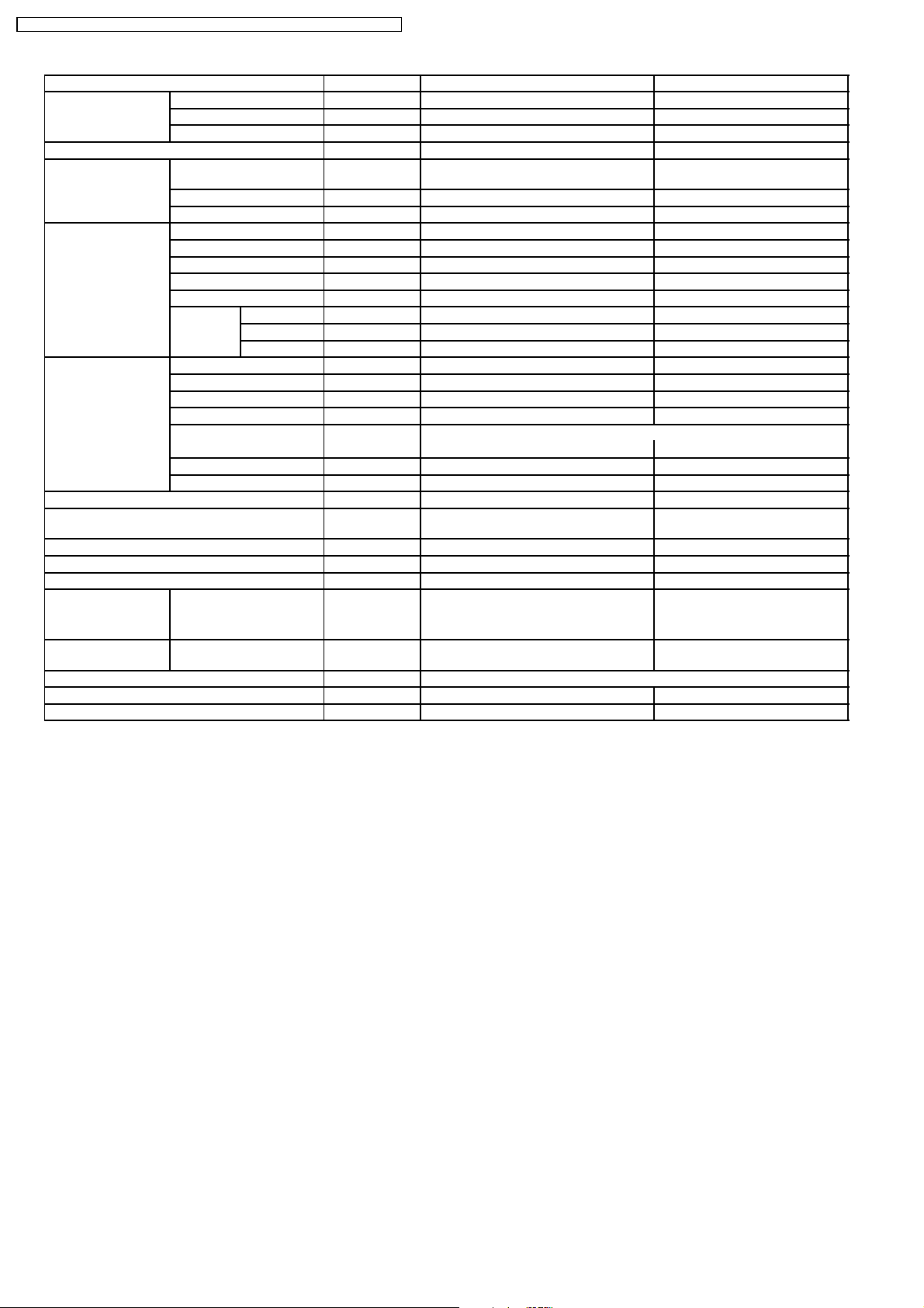
Unit CS-A24ATP5 CU-A24ATPT5
Cooling Capacity kW
BTU/h
kcal/h
Heating Capacity kW
BTU/h
kcal/h
Moisture Removal l/h
Pint/h
Power Source Phase
V
Cycle
Airflow Method OUTLET
SIDE VIEW TOP VIEW
6.00; 6.05; 6.10
20,400; 20,600; 20,800
5,140; 5,190; 5,240
6.00; 6.05; 6.20
20,400; 20,600; 21,100
5,140; 5,190; 5,310
3.4
7.2
Single
220; 230; 240
50
INTAKE
Air Volume Indoor Air (Lo) m3/min (cfm) 10.4 (370) —
Indoor Air (Me) m3/min (cfm) 11.2 (395) —
Indoor Air (Hi) m3/min (cfm) 12.0 (420) —
Noise Level dB (A) Cooling: High 51; 52; 52 Low 45; 47; 47
Heating: High 51; 52; 52 Low 45; 47; 47
Cooling: High 57; 59; 59
Heating: High 58; 60; 60
Power Noise Level dB (A) Cooling: High 65
Heating: High 65
Electrical Data Input kW Cooling: 2.75; 2.80; 2.89
Heating: 2.40; 2.59; 2.62
Running Current A Cooling: 13.3; 13.4; 13.6
Heating: 11.7; 12.3; 12.5
EER W/W (BTU/hW) Cooling: 2.18 (7.4); 2.16 (7.4); 2.11 (7.2)
COP W/W (BTU/hW) Heating: 2.50 (8.5); 2.33 (8.0); 2.37 (8.1)
Starting Current A 59
Piping Connection Port
(Flare piping)
Pipe Size
(Flare piping)
Drain
Hose
Power Cord Length
Number of core-wire
Inner diameter mm 20 —
Length m 0.6 —
inch
inch
inch
inch
G ; Half Union 5/8”
L ; Half Union 1/4”
G (gas side) ; 5/8”
L (liquid side) ; 1/4”
m 2.3
3 (2.5 mm
2
)
Cooling: High 74
Heating: High 75
G ; 3-way valve 5/8”
L ; 2-way valve 1/4”
G (gas side) ; 5/8”
L (liquid side) ; 1/4”
—
—
9
Page 10
CS-A12ATP5 CU-A12ATP5 / CS-A18ATP5 CU-A18ATPT5 / CS-A24ATP5 CU-A24ATPT5
Unit CS-A24ATP5 CU-A24ATPT5
Dimensions Height inch (mm) 6 - 1/2 (165) 26 - 31/32 (685)
Width inch (mm) 43 - 5/16 (1,100) 31 - 1/2 (800)
Depth inch (mm) 25 - 19/32 (650) 11 - 13/16 (300)
Net Weight lb (kg) 66 (30) 137 (62)
Compressor Type — Rotary (1 cylinder)
Motor Type — Induction (2-poles)
Rated Output W — 2,200
Air Circulation Type SIROCCO Propeller Fan
Material STYLAC 181 CE10G15 JSR
Motor Type Induction (4-poles) Induction (4-poles)
Input W 66.0 141.7 (High)
Rated Output W 40 80
Fan Speed Low rpm 1,160 685
Medium rpm 1,250 —
High rpm 1,340 1,053
Heat Exchanger Description Evaporator Condenser
Tube material Copper Copper
Fin material Aluminium Aluminium
Fin Type Louver Fin Corrugated Fin
Row / Stage (Plate fin configuration, forced draft)
2 × 10 2 × 26
FPI 20 14
Size (W × H × L) mm 900 × 254 × 44 769 × 660 × 44
Refrigerant Control Device — Capillary Tube
Refrigeration Oil (c.c) — SUNISO 4GDID or ATMOS M60
Refrigerant (R-22) g (oz.) — 1,900 (67.1)
Thermostat Electronic Control —
Protection Device — Inner Protector
Length mm — 1,170
Capillary Tube Flow Rate l/min — 21.1
Inner Diameter mm — 2.4
Air Filter Material
Style
Capacity Control Capillary Tube
Compressor Capacitor µF, VAC — 45 µF, 370VAC
Fan Motor Capacitor µF, VAC 1.2 µF, 450VAC 3.5 µF, 400VAC
P.P.
Honeycomb
rolling piston type
(700)
—
•
Specifications are subject to change without notice for further improvement.
10
Page 11
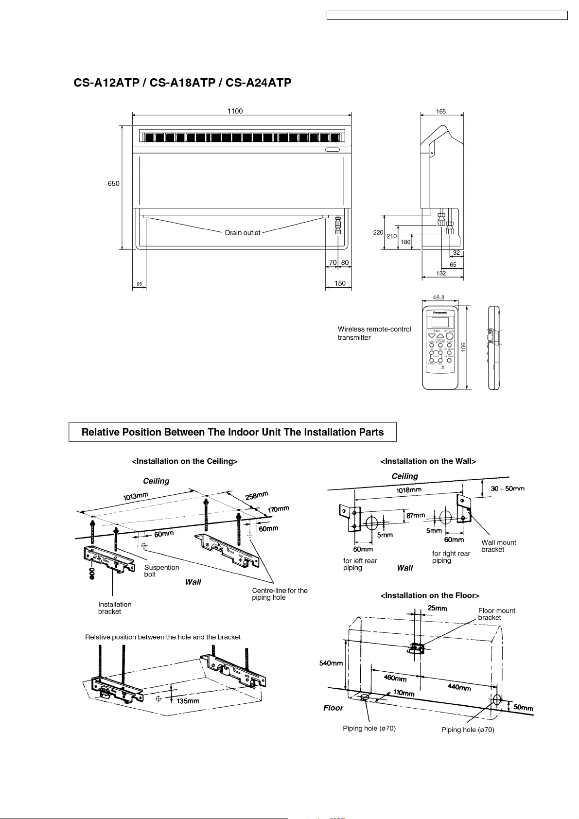
3 Dimensions
CS-A12ATP5 CU-A12ATP5 / CS-A18ATP5 CU-A18ATPT5 / CS-A24ATP5 CU-A24ATPT5
11
Page 12
CS-A12ATP5 CU-A12ATP5 / CS-A18ATP5 CU-A18ATPT5 / CS-A24ATP5 CU-A24ATPT5
12
Page 13
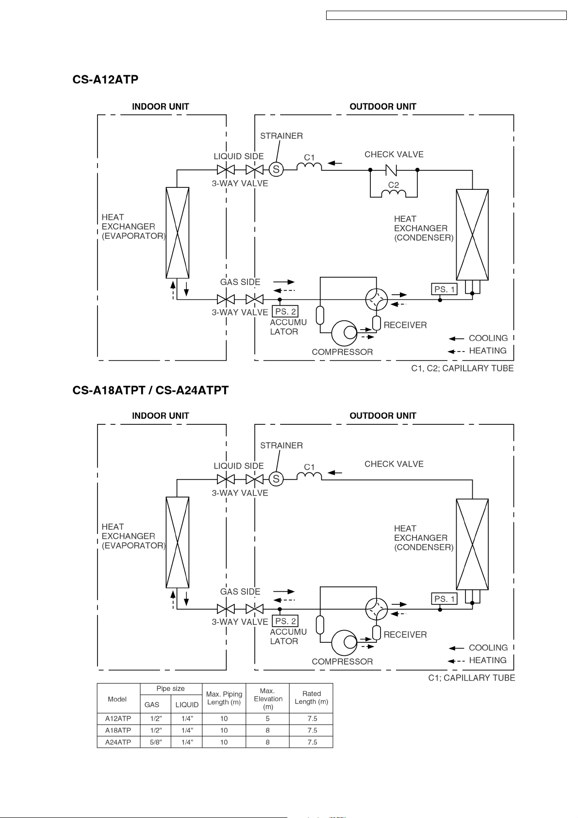
4 Refrigeration Cycle Diagram
CS-A12ATP5 CU-A12ATP5 / CS-A18ATP5 CU-A18ATPT5 / CS-A24ATP5 CU-A24ATPT5
13
Page 14

CS-A12ATP5 CU-A12ATP5 / CS-A18ATP5 CU-A18ATPT5 / CS-A24ATP5 CU-A24ATPT5
5 Block Diagram
14
Page 15
CS-A12ATP5 CU-A12ATP5 / CS-A18ATP5 CU-A18ATPT5 / CS-A24ATP5 CU-A24ATPT5
15
Page 16
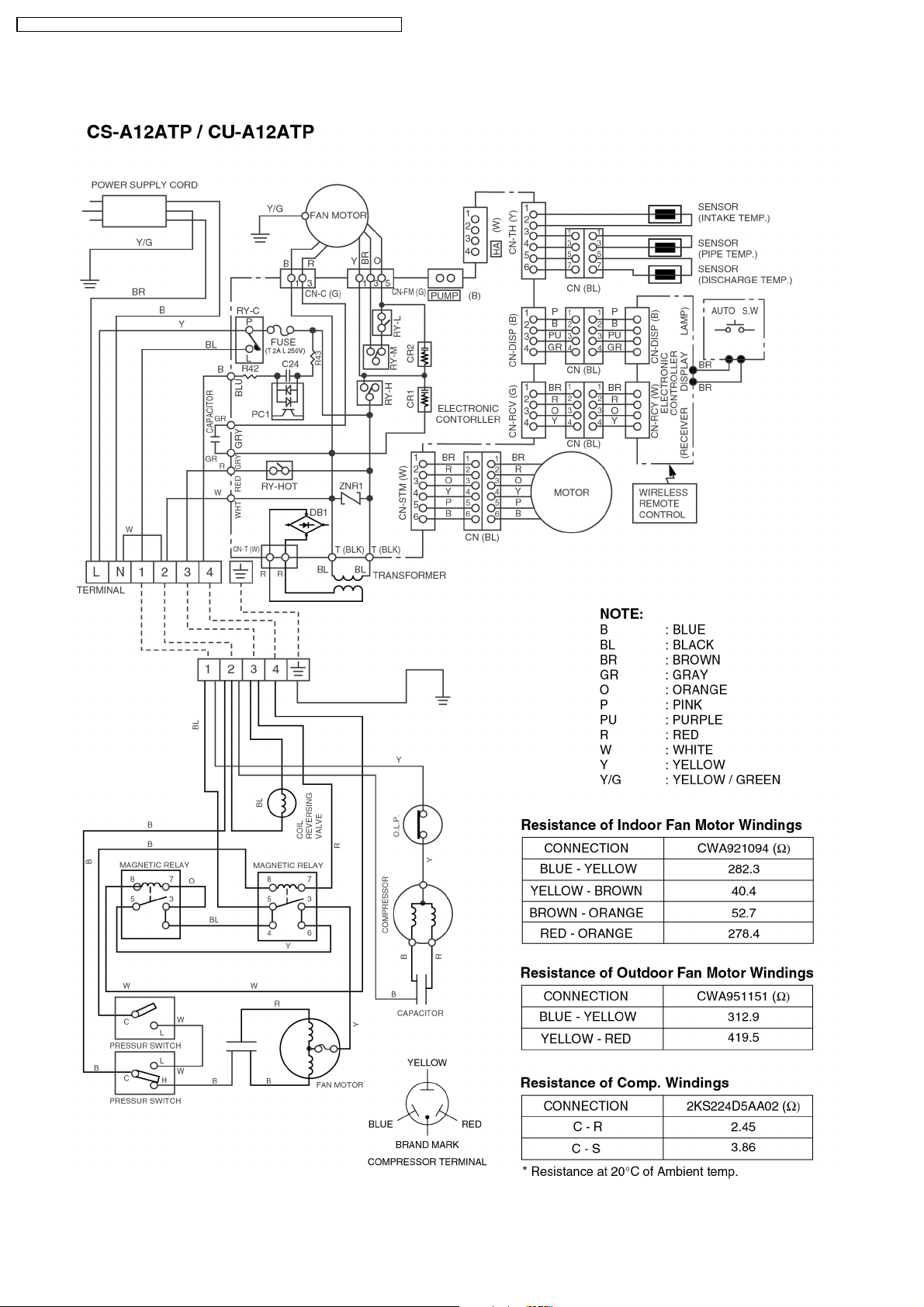
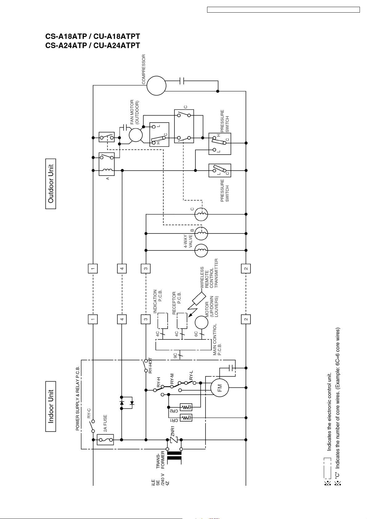
CS-A12ATP5 CU-A12ATP5 / CS-A18ATP5 CU-A18ATPT5 / CS-A24ATP5 CU-A24ATPT5
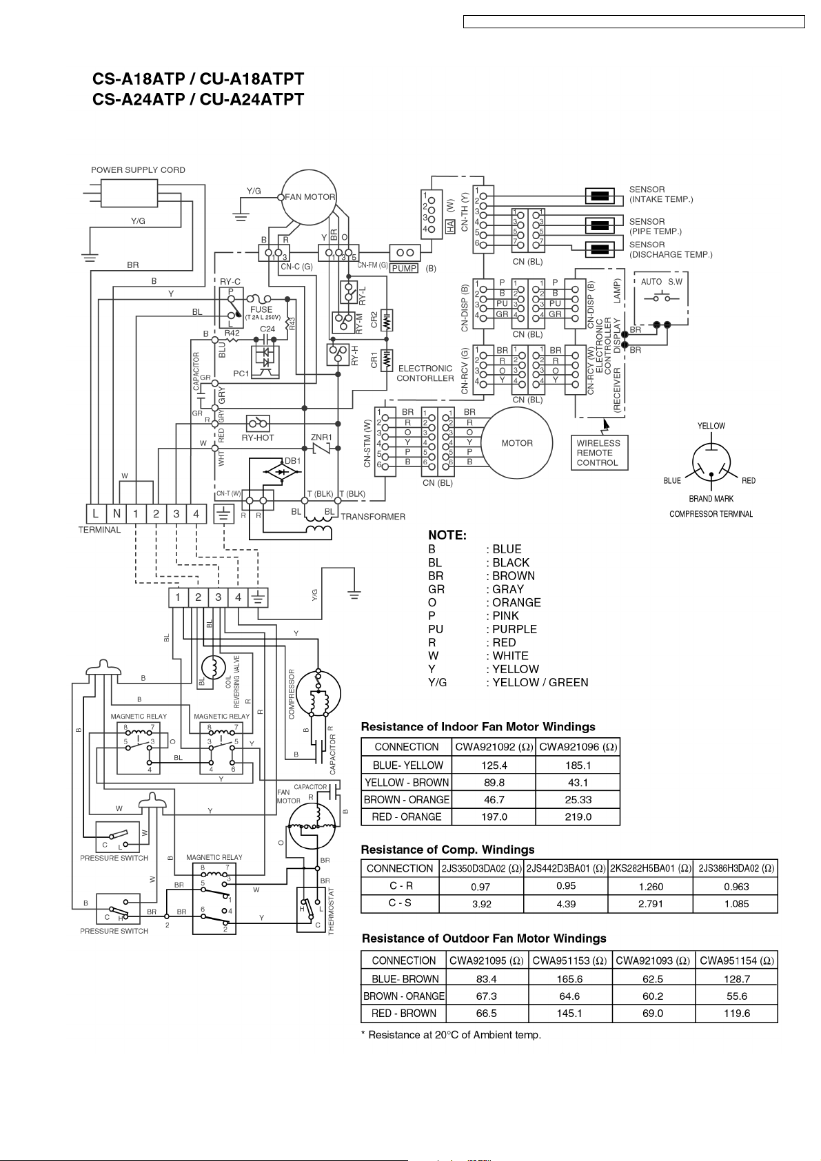
6 Wiring Diagram
16
Page 17
CS-A12ATP5 CU-A12ATP5 / CS-A18ATP5 CU-A18ATPT5 / CS-A24ATP5 CU-A24ATPT5
17
Page 18

CS-A12ATP5 CU-A12ATP5 / CS-A18ATP5 CU-A18ATPT5 / CS-A24ATP5 CU-A24ATPT5
7 Operation Details
7.1. Cooling Mode Operation
When selecting the Cooling (COOL) Mode Operation, the unit will operate according to the setting by the Remote Control and
the operation is as the following.
Time Delay Safety Control
3 min. --- The Compressor is ceased for 3 minutes to balance the pressure in the refrigeration cycle.
(Protection of compressor)
Automatic Restarting Control
7 min. --- The unit will automatically operate in 7 minutes even if the room temperature is not reached.
(Protection of raising the humidity)
Compressor Forced Operation Control
30 sec. --- The compressor is switched ON at once, it is to be operated for 30 seconds.
(Protection of compressor)
7.2. Soft Dry Mode Operation
When selecting the Soft Dry (DRY) Mode Operation, the operation will be cooling until the Room Temperature reaches the Set
Temp. on the remote control, and then Soft Dry will activate.
(During Soft Dry operation, the fan of the indoor unit will operate at Low fan speed and stop at 4-second intervals, and operation
will be switched on and off for up to 10 minutes on and 6 minutes off.)
18
Page 19

7.3. Detail of Sleep Mode
Sleep Mode operates to match your sleeping condition.
At Cooling or Soft Dry operation
1.
When you set the Sleep Mode (SLEEP), the following
movement will start to avoid overcooling.
The fan speed is automatically set to low.
•
The setting temperature will be rise by 1°C at the
•
start of operation and by 1°C one hour later.
The Automatic Restarting Control is changed from 7
•
minutes to 5 minutes.
The operation will stop after 5 hours.
•
At Heating operation
2.
When you set the Sleep Mode (SLEEP), the following
movement will start to avoid overheating.
The fan speed is automatically set to low.
•
The setting temperature will dropped by 2°C at the
•
start of operation and by 3°C one hour later.
The operation will stop after 5 hours.
•
CS-A12ATP5 CU-A12ATP5 / CS-A18ATP5 CU-A18ATPT5 / CS-A24ATP5 CU-A24ATPT5
7.4. Heating Mode Operation
When selecting the Heating (HEAT) Mode Operation, the unit will operate according to the setting by the Remote Control and
the operation is as the following.
(1) Room temperature can be set in 1°C steps in the range of
16 to 30°C. Relationship between the remote control
temperature adjustment knob and operation is shown in
the diagram below.
(2) Taking the difference between the room temperature
distribution and intake air temperature, heating ON
temperature is set to 3°C higher than the remote control
setting.
19
Page 20

CS-A12ATP5 CU-A12ATP5 / CS-A18ATP5 CU-A18ATPT5 / CS-A24ATP5 CU-A24ATPT5
7.5. Deice control
Deicing operation is controlled by sensing the indoor piping temperature and timer.
•
Deicing starts when 60 minutes after start of heating or deice ends and if the indoor piping temperature is 46° (°C) or lower.
•
Deicing ends by function of the pressure switch or after 9 minutes of deice operation.
•
7.6. Airflow direction control
Manual operation
1.
When the airflow direction adjustment button of the remote
control is pressed, the louver moves up/down in the
movable range shown in the diagram at right, and can be
stopped at the required position.
Only the up/down louvers are adjustable from the remote
control.
Automatic airflow direction
2.
a. For cooling and soft dry
The up/down louver swings within the movable range.
b. For heating
As shown in the diagram at left, the blow out angle
changes according to the blow out temperature.
* Angle of the left/right louver is manually adjusted.
7.7. Automatic operation
When AUTO (automatic operation) is set with the “operation
mode selector” on the remote control, the indoor fan runs at
Low speed for 20sec., the air conditioner unit senses the room
temperature then automatically selects the operation mode and
temperature setting.
1. Relationship between room temperature at start and
operation mode:
* Operation lamp flashes while fan is running for the first
20sec., then lights.
* At start of operation, if the room temperature i s 16°Cor
lower, heating operation (hot start) starts immediately.
* Once the operation mode is determined by automatic
operation, that operation mode does not change unless
the air conditioner is stopped once and restarted or by
changing to a different mode using the operation mode
select button.
2. The 3 temperature settings listed below can be selected for
* High : +2 degrees up
* Standard :+0
* Low : -2 degrees down
20
Page 21

8 Operating Instructions
CS-A12ATP5 CU-A12ATP5 / CS-A18ATP5 CU-A18ATPT5 / CS-A24ATP5 CU-A24ATPT5
SAFETY PRECAUTIONS
Before operating, please read the following
“Safety Precautions” carefully.
● To prevent personal injury, injury to others and
property damage, the following instructions must be
followed.
● Incorrect operation due to failure to follow instructions
will cause harm or damage, the seriousness of which
is classified as follow:
!
This sign warns of death or serious injury.
This sign warns of damage to property.
● The instructions to be followed are classified by the
following symbols:
This symbol (with a white background) denotes an
These symbols (with a black background) denote
Warning
!
Caution
action that is PROHIBITED.
F
F
O
actions that are COMPULSORY.
■ Installation Precautions
!
Warning
● Do not install, remove and reinstall the unit by
yourself.
Improper installation will cause leakage, electric
shock or fire. Please engage an authorized dealer
or specialist for the installation work.
!
Caution
● This room air conditioner must be
earthed.
Improper grounding could cause
electric shock.
● Ensure that the drainage piping is
connected properly.
Otherwise, water will leak out.
● Do not install the unit in a
potentially explosive atmosphere.
Gas leak near the unit could cause
fire.
■ Operation Precautions
!
This sign warns of death or serious injury.
● Do not share outlet.
● Do not insert plug to operate the unit. Do not
● Do not operate with wet hands.
● Do not damage or modify the power cord.
● Do not insert finger or other objects into the
●
● Plug in properly.
● Use specified power cord.
F
F
O
● If abnormal condition (burnt smell, etc.)
● Do not pull the cord to disconnect the plug.
● Do not wash the unit with water.
● Do not use for other purposes such as
● Do not use any combustible equipment at
●
● Switch off the power supply before cleaning.
● Ventilate the room regularly.
● Pay attention as to whether the installation
F
F
O
● Switch off the power supply if the unit is not
Warning
pull out plug to stop the unit.
indoor or outdoor units.
Do not expose directly to cold air for a long period.
occurs, switch off and unplug the power
supply.
!
Caution
This sign warns of injury.
preservation.
airflow direction.
Do not sit or place anything on the outdoor unit.
rack is damaged after long period of usage.
used for a long period.
NAME OF EACH PART
■ Indoor Unit
1
6
5
4
1 Air Outlet Vent
2 Power Supply Cord
3 Air Intake Vent
4 Air Filters (behind the panel)
5 Horizontal Airflow Direction Louver
(manually adjusted)
6 Vertical Airflow Direction Louver
● Indoor Unit Controls
1 Operation Indication Lamps
2 Signal Receptor
3 Auto Operation Button
AUTO
OFF/ON
2
3
12345
1 Auto Operation Button
2 Power Mode Indicator – GREEN
■ Accessories
● Remote Control
A
U
T
O
C
O
O
L
D
R
Y
F
A
N
C
O
F
F
H
O
T
N
EM
O
F
F
H
P
O
N
O
F
M
F
O
/
D
O
E
N
S
L
E
E
P
F
A
N
S
P
E
E
D
TIMER
A
U
O
T
O
N
/
O
F
F
AIR SWING
S
E
T
/C
M
A
R
E
N
S
U
E
A
T
L
F
A
N
SP
E
ED
SLEEP
TIMER AIR SWING
POWER
3 Timer Mode Indicator – ORANGE
4 Air Swing Mode Indicator – RED
● Remote Control Indication Sticker
5 Sleep Mode Indicator – ORANGE
■ Outdoor Unit
1
1
2
3
1 Air Intake Vents
2 Piping
3 Drain Hose
4 Connecting Cable
5 Air Outlet Vents
5
2
● Remote Control Holder
3
4
● Two RO3 (AAA) dry-cell batteries or equivalent
21
Page 22

CS-A12ATP5 CU-A12ATP5 / CS-A18ATP5 CU-A18ATPT5 / CS-A24ATP5 CU-A24ATPT5
NAME OF EACH PART
■ Remote Control
1
2
AUTO
COOL
DRY
FAN
3
MODE SLEEP
4
5
6
7
OFF/ON SET/C
● Remote Control Signal.
• Make sure it is not obstructed.
• Maximum distance : 10 m.
• Signal received sound.
One short beep or one long beep.
● Notes for Remote Control.
• Do not throw or drop.
• Do not get it wet.
• Certain type of fluorescent lamps may affect
signal reception. Consult your dealer.
● Do not place the remote control in a location exposed
to direct sunlight, or next to a heating unit, or other
heat source.
OFF ON OFF ON
TEMP
TIMER
C
H H
OFF/ON
RESET
FAN
SPEED
FAN SPEED
AUTO
AIR SWING
MANUAL
8
9
!
"
#
$
1 Signal Transmitter
2 Operation Display
Cooling Model
AUTO
COOL
DRY
FAN
OFF ON OFF ON
C
H H
FAN
SPEED
Heat Pump Model
AUTO
HEAT
COOL
OFF ON OFF ON
DRY
3 Room Temperature Setting Button
(self-illuminating button)
C
H H
FAN
SPEED
4 Operation Mode Selection Button
5 Sleep Mode Operation Button
(self-illuminating button)
6 Timer Setting Button
7 Timer Selection Button
8 OFF/ON Button
(self-illuminating button)
9 Fan Speed Selection Button
0 Auto Airflow Direction Button
! Timer Set/Cancel Button
@ Manual Airflow Direction Selection Button
# Reset Point
(Press with fine-tipped object to clear the memory)
● How to Insert the Batteries
1
.5V
1
.5
1
1
Gently press the place marked OPEN and slide
the cover towards you.
2
Insert the batteries
– Be sure the direction is correct.
● About the batteries
• Can be used for approximately one year.
Observe the following when replacing the batteries
●
• Replace with new batteries of the same type.
• Do not use rechargeable batteries (Ni-Cd).
• Remove the batteries if the unit is not going to be
used for a long period.
● Proper way to operate the remote control in the
case of ceiling/wall mounting.
• Operate the remote control in parallel with the floor.
(See the figure below)
V
O
P
E
N
(Fig. 1) Horizontal Level
• The signal changes as shown in the figure below.
It means that the receiving conditions are bad and
the signal can not be controlled properly.
(Fig. 2)
2
O.K.
OUT
PREPARATION BEFORE OPERATION
■ Indoor Unit
1 Connect the power supply cord to an independent
power supply.
HOW TO OPERATE
A
U
T
O
C
O
O
L
D
R
Y
F
A
3
2
ON
■ To start the operation
• Press 1.
• POWER indicator (green) on the indoor unit will light
up.
• To stop, press once more.
■ Setting Mode
• Press 2 to select:-
AUTO – Automatic Operation
COOL – Cooling Operation
DRY – Soft Dry Operation
FAN – Air Circulation Operation
AUTO – Automatic Operation
HEAT – Heating Operation
COOL – Cooling Operation
DRY – Soft Dry Operation
T
M
O
D
E
SLE
EP
T
IM
E
R
/O
F
F
A
IR
S
S
W
ET
IN
/C
G
M
AN
RESET
UA
L
Cooling Model
Heat Pump Model
N
C
O
FF
H
FAN
O
E
N
S
P
M
OFF
E
E
D
P
H
ON
O
F
F
/O
N
FA
N S
PEE
A
U
TO
1
D
4
6
5
■ Setting Temperature
• Press 3 to increase or decrease the temperature.
• The temperature can be set between:
Cooling Model : 20°C ~ 30°C
Heat Pump Model : 16°C ~ 30°C
• Recommended temperature:
Cooling Model
COOL – 26°C ~ 28°C
DRY – 1°C ~ 2°C
lower than the
room temperature
Heat Pump Model
COOL – 26°C ~ 28°C
DRY – 1°C ~ 2°C
lower than the
room temperature
HEAT – 20°C ~ 24°C
• During AUTO Operation, press 3 to select:-
• Operation with 2°C higher than the standard
temperature.
• Operation with the standard temperature.
• Operation with 2°C lower than the standard
temperature.
● Standard Temperature
Cooling Model
Indoor
temperature
24°C
• Once the Automatic Operation is selected, the indoor
temperature sensor operates automatically to select
the desired operation mode with Cooling or Soft Dry.
• After the operation mode has been selected, the
mode does not change.
Operation
Cooling
Soft Dry
Standard
temperature
27°C
24°C
Heat Pump Model
Indoor
temperature
25°C
21°C
• At the beginning of the automatic operation, Heating,
Cooling or Soft Dry is automatically selected according
to the indoor temperature.
• After the operation mode has been selected, the
mode does not change.
Operation
Cooling
Soft Dry
Heating
Standard
temperature
27°C
24°C
22°C
22
Page 23

CS-A12ATP5 CU-A12ATP5 / CS-A18ATP5 CU-A18ATPT5 / CS-A24ATP5 CU-A24ATPT5
■ Setting the Fan Speed
• Press 4 to select:-
– Low Fan Speed
– Medium Fan Speed
– High Fan Speed
■ Vertical Airflow Direction
● Manual Operation
• Press and hold the Manual Airflow Direction
Selection Button 5 , then release at the desired
airflow direction.
• Cooling / Soft Dry / Heating
The airflow direction can be adjusted as desired
by using the remote control. This is effective
when you want to cool yourself directly, such as
when coming out of the bath. The louver can be
adjusted within a range between the horizontal
and 30 degrees downward at Cooling and Soft
Dry Operation, and between the horizontal and
60 degrees downward at Heating Operation.
Horizontal
Downward
● Automatic Operation
• Press the Auto Airflow Direction Button 6.
• Cooling / Soft Dry
The louver will automatically swing up and down
to create the feeling of a refreshing breeze.
Swing up
and down
• Heating
Horizontal
When the airflow
temperature is low
Downward
When the airflow
temperature become warm
■ Setting the Horizontal Airflow Direction
• Adjust it manually
● Use this air conditioner under the following
conditions:
Cooling Model
(Unit in °C)
DBT: Dry Bulb Temp
WBT: Wet Bulb Temp
Maximum Temperature
Minimum Temperature
Indoor Outdoor
DBT
WBT
DBT
32
23
20
14
WBT
43
26
20
14
Heat Pump Model
(Unit in °C)
Outdoor
DBT: Dry Bulb Temp
WBT: Wet Bulb Temp
Maximum Temperature-Cooling
(Maximum Temperature-Heating)
Minimum Temperature-Cooling
(Minimum Temperature-Heating)
● Notes
• If the unit is not going to be used for an extended
period of time, turn off the main power supply. If it is
left at the ON position, approximately 2.0 W of
electricity will be used even if the indoor unit has been
turned off with the remote control.
• If operation is stopped, then restart immediately, the
unit will resume operation only after 3 minutes.
DBT
(30)
(16)
Indoor
32
16
WBT
DBT
WBT
23
43
26
(-)
(24)
(18)
11
16
11
(-)
(-5)
(-6)
● Operation Details
COOL – Cooling Operation
• To set the room temperature at your preference
cooling comfort.
AUTO – Automatic Operation
• Sense indoor temperature to select the optimum
mode.
• Temperature is not displayed on the remote control
during AUTO operation.
DRY – Soft Dry Operation
• A very gentle Cooling Operation, prior to
dehumidification. It does not lower the room
temperature.
• During Soft Dry operation, the indoor fan operates at
Low Fan Speed for 10 minutes (ON and OFF for 4
seconds intervals) then OFF for 6 minutes. This
operation will be repeated.
HEAT – Heating Operation
(for Heat Pump Model only)
• Heat is obtained from outdoor air to warm up the
room. When the outdoor ambient air temperature
falls, the heating capacity of the unit might be
reduced.
• Defrosting Operation
Depend on the outdoor temperature, the operation
occasionally stops to melt the frost on the outdoor
unit.
FAN – Air Circulation Operation
(for Cooling Model only)
• Heated air rises and collects at the top of the room.
The air circulation circulates the heated air downward,
thus increasing heating effectiveness. When the unit
is installed floor mounted, you should set the
temperature higher than that of ceiling mounted.
At ceiling mounted At floor mounted
5
3
2
ON
1
SETTING THE TIMER
The Delay ON-Timer and Delay OFF-Timer cannot be
selected simultaneously.
/OFF
4
A
U
T
O
C
O
O
L
D
R
Y
F
A
N
C
O
F
F
H
T
FAN
O
E
N
S
P
M
O
E
F
E
F
D
P
H
O
N
O
F
M
F
O
/O
DE
N
SLEEP
FAN SPEED
T
IM
ER
AUTO
A
IR
S
SET/C
W
ING
R
E
S
E
T
• Press the Timer Selection Button 1.
• Select one of the following five types of operation.
Each time the button is pressed, the operation mode
is shifted in the arrow direction.
Delay OFF Timer Example :
H
OFF
Delay ON Timer Example :
H
ON
Delay OFF and Example :
ON Timer Operation stops after
Delay ON and Example :
OFF Timer Operation starts after
• Then press the Timer Setting Button 2 or 3 to the
desired number of hours.
(Number of hours which can be set : 1 ~ 12)
• Press the Timer Set/Cancel Button 4
H
OFF
H
ON
H
ON
H
OFF
Operation Stops
after 1 hour
ON Timer.
Operation starts after
6 hours.
1 hour and re-starts
after another 5 hours.
10 hours, and then
stops after another 8
hours.
CONVENIENCE OPERATION
■ Sleep Mode Operation
To obtain a comfortable room temperature while
sleeping:-
• Press 5.
• Sleep mode indicator on the indoor unit will light up.
• To cancel this operation, press once more.
● Sleep Mode Operation Details
• When the room temperature reaches the set
temperature, the airflow volume will change to low
automatically.
• Sleep Mode Operation time is 5 hours.
• When used together with the timer, the timer has a
priority.
Cooling Model
When the room temperature
become a level ideal for
sleep, the operation 10
minutes on and 20 minutes
off will be repeated.
Temperature
S
T
e
e
m
t
p
t
e
i
r
n
a
g
t
u
r
e
Sleep
Operation
button is
pressed.
0~1 hour ← 1 hour →
Approx. 1°C
increase.
Approx.
1°C
increase.
• Cooling or Soft Dry
Operation for sleep shift
operation will start to
Sleep shift
avoid overcooling.
operation
starts.
after approx. 5 hours of sleep shift
operation, it will stop automatically.
Heat Pump Model
Temperature
S
T
e
e
m
t
p
t
e
i
r
n
a
g
t
u
r
e
Sleep
Operation
button is
pressed.
0~1 hour
Approx. 1°C
increase.
Approx.
1°C
increase.
Sleep shift
operation starts.
Approx. 2°C
decrease.
← 1 hour →
← 1 hour →
after approx. 5 hours of sleep shift
operation, it will stop automatically.
• Cooling or Soft Dry
Operation for sleep shift
operation will start to
avoid overcooling.
• Heating operation for
sleep shift operation will
start to avoid overheating.
Approx. 3°C
decrease.
Time
CARE AND MAINTENANCE
■ Cleaning the Indoor Unit and Remote
Control
• Wipe gently with a soft, dry cloth.
• Do not use water hotter than 40˚C or polishing fluid
to clean the unit.
■ Cleaning the Air Filter
(Recommendation:- If the unit is operated in a dusty
environment, clean the filters every two weeks,
continuous use of this dirty filters will reduce cooling
or heating efficiency)
1 Remove dirt using a vacuum cleaner.
2 Wash back of the air filter with water.
3 If badly soiled, wash it with soap or a mild household
detergent.
4 Let it dry and reinstall it.
Be sure the “FRONT” mark is facing you.
* Damaged air filter.
Consult the nearest authorized dealer.
Part No.: CWD00112.
• Do not use benzene, thinner, scouring powder or
clothes soaked in caustic chemical to clean the
unit.
Time
23
Page 24

CS-A12ATP5 CU-A12ATP5 / CS-A18ATP5 CU-A18ATPT5 / CS-A24ATP5 CU-A24ATPT5
■ Pre-season Inspection
● Clean the air filters, re-insert and operate the air
conditioners.
● Is the discharged air cold / warm?
Operation is normal if 15 minutes after the start of
operation, the difference between the air intake and
outlet vents temperature is:-
Cooling Model
COOL – 8°C or above
Heat Pump Model
COOL – 8°C or above
● Are the air intake or outlet vents of the indoor or
outdoor units obstructed?
● Are the remote control batteries weak?
If the remote control display appears weak, replace
the batteries.
HEAT – 14°C or above
■ When the Air Conditioner is Not Used
for an Extended Period of Time
1 To dry the internal parts of the indoor unit, operate
the unit for 2 - 3 hours using:-
2 Turn off the power supply and unplug.
Note: If the unit is not switched off by the remote control,
it will start operating when you plug in (because the unit
is equipped with Auto Restart Control).
3 Remove the remote control batteries.
■ Recommended Inspection
•
After used over several seasons, the unit will become
dirty and thus decreases the unit’s performance.
Depending on the operation conditions, a dirty unit
may produce odour and dust may pollute
dehumidification system. Therefore, a seasonal
inspection is recommended in addition to regular
cleaning. (Consult an authorized dealer).
Cooling Model
FAN operation
Heat Pump Model
COOL operation with
30°C set temperature
HELPFUL INFORMATION
■ Auto Operation
Press the Auto Operation Button
AUTO
OFF/ON
● Automatic Operation
• If the remote control fails to function or has been
misplaced, press the Auto Operation button to start
the Automatic operation.
• The Automatic operation will be activated
immediately once the Auto operation button is
pressed. However, temperature cannot be adjusted
in this operation.
• The power indicator on the indoor unit will blink until
the operation mode is selected automatically.
• To cancel this operation, press once more.
■ Timer Setting
• When power failure occurs, the timer setting will be
cancelled. Once power is resumed, reset the timer.
■ Thunder and Lightning
• This air conditioner is equipped with a built-in surge
protective device. However, in order to further
protect your air conditioner from being damaged by
abnormally strong lightning activity, you may switch
off the main power supply and unplug from power
socket.
ENERGY SAVING AND OPERATION
HINTS
■ Setting the Temperature
• Approximately 10% of electricity can be saved.
• Set the temperature higher or lower than the
desired temperature.
Cooling Model
Cooling Operation : 1°C higher
Heat Pump Model
Cooling Operation : 1°C higher
Heating Operation : 2°C lower
■ Air Filters
• Clean the air filters every 2 weeks.
• Dirty filters may reduces cooling or heating
efficiency.
■ Keep All Doors and Windows Closed
• Otherwise, cooling or heating performance will be
reduced and electricity cost is wasted.
■ Outdoor Unit
• Do not block the air outlet vents. Otherwise, it will
lower the cooling or heating performance.
■ Timer and Sleep Mode
• To prevent wastage of electricity, use sleep mode
when sleeping or Timer when going out.
■ Avoid Direct Sunlight
• Keep curtains or drapes closed to avoid direct
sunlight during cooling operation.
TROUBLESHOOTING
■ Normal Operation
Is it okay?
• Air conditioner has been restarted, but does not
operate for 3 minutes.
• A sound like water flowing can be heard.
• It seems that fog is coming out from the air
conditioner.
• The room has a peculiar odour.
• The outdoor unit emits water or steam.
• (For Heat Pump Model only)
Operation stops for about 9 minutes during
heating (The power indicator blinks).
• (For Heat Pump Model only)
During heating operation, indoor fan may
run at on and off conditions.
■ Abnormal Operation
Is it okay?
• The air conditioner does not operate.
• Air conditioner produces loud noise during
operation.
• The air conditioner does not cool or warm
effectively.
This is the answer
• This is to protect the air conditioner. Wait until the air
conditioner begins to operate.
• This is the sound of refrigerant flowing inside the air
conditioner.
• Condensation occurs when the airflow from the air
conditioner cools the room.
• This may be a damp smell emitted by the wall,
carpet, furniture or clothing in the room.
• In COOL/DRY operation, moisture in the air
condenses into water on the cool surface of outdoor
unit piping that causes dripping.
• This is to melt the frost which has accumulated on
the outdoor unit (defrosting operating). This will take
no longer than about 9 minutes. Water drips from
the outdoor unit. Wait until this operation ends.
(the power indicator will light up). (Frost will
accumulates on the outdoor unit when the outdoor
temperature is low and humidity is high.)
• This is to prevent undesired cooling effect during
heating operation.
Please check
• Has the circuit breaker been tripped?
• Has the power plug been removed from the wall
outlet?
• Is the timer being used correctly?
• Is the installation work slanted?
• Is the front grille closed properly?
• Has the temperature been set incorrectly?
• Are the filters dirty?
• Are the intake or outlet vents of the outdoor unit
obstructed?
• Are all windows and doors closed?
■ Call the Dealer Immediately
If the following conditions occur, turn off and unplug the
main power supply, and then call the dealer immediately.
• Abnormal noise is heard during operation.
• Water or foreign material gets into the remote
control by mistake.
• Water leak from the indoor unit.
• Switches or buttons do not operate properly.
• The circuit breaker switches off frequently.
• Power supply cord and plug become unusually
warm.
24
Page 25

CS-A12ATP5 CU-A12ATP5 / CS-A18ATP5 CU-A18ATPT5 / CS-A24ATP5 CU-A24ATPT5
9 Installation Instructions
Required tools for Installation Works
1. Philips screw driver 5. Spanner 9. Gas leak detector 13. Multimeter
2. Level gauge 6. Pipe cutter 10. Measuring tape 14. Torque wrench
3. Electric drill, hole core drill
(ø70 mm)
4. Hexagonal wrench (4 mm) 8. Knife 12. Megameter 16. Gauge manifold set
7. Reamer 11. Thermometer 15. Vacuum pump
9.1. Safety Precautions
•
Read the following “SAFETY PRECAUTIONS” carefully before installation.
•
Electrical work must be installed by a licensed electrician. Be sure to use the correct rating of the power plug and main circuit
for the model to be installed.
•
The caution items stated here must be followed because these important contents are related to safety. The meaning of each
indication used is as below. Incorrect installation due to ignoring of the instruction will cause harm or damage, and the
seriousness is classified by the following indications.
This indication shows the possibility of causing death or serious injury.
18 N.m (1.8 kgf.m)
55 N.m (5.5 kgf.m)
65 N.m (6.5 kgf.m)
This indication shows the possibility of causing injury or damage to properties only.
The items to be followed are classified by the symbols:
Symbol with background white denotes item that is PROHIBITED from doing.
•
Carry out test running to confirm that no abnormality occurs after the installation. Then, explain to user the operation, care and
maintenance as stated in instructions. Please remind the customer to keep the operating instructions for future reference.
1. Engage dealer or specialist for installation. If installation done by the user is defective, it will cause water leakage, electrical shock or fire.
2. Install according to this installation instruction strictly. If installation is defective, it will cause water leakage, electrical shock or fire.
3. Use the attached accessories parts and specified parts for installation. Otherwise, it will cause the set to fall, water leakage, fire or
electrical shock.
4. Install at a strong and firm location which is able to withstand the set’s weight. If the strength is not enough or installation is not properly
done, the set will drop and cause injury.
5. For electrical work, follow the local national wiring standard, regulation and this installation instruction. An independent circuit and single
outlet must be used. If electrical circuit capacity is not enough or defect found in electrical work, it will cause electrical shock or fire.
6. Use the specified cable and connect tightly for indoor/outdoor connection. Connect tightly and clamp the cable so that no external force
will be acted on the terminal. If connection or fixing is not perfect, it will cause heat-up or fire at the connection. The outlet cable shall be
fastened by the two clamps of the indoor unit.
7. Wire routing must be properly arranged so that control board cover is fixed properly. If control board cover is not fixed perfectly, it will
cause heat-up at connection point of terminal, fire or electrical shock.
8. When carrying out piping connection, take care not to let air substances other than the specified refrigerant go into refrigeration cycle.
Otherwise, it will cause lower capacity, abnormal high pressure in the refrigeration cycle, explosion and injury.
9. Do not damage or use unspecified power supply cord. Otherwise, it will cause fire or electrical shock.
10. Do not modify the length of the power supply cord or use of the extension cord, and do not share the single outlet with
other electrical appliances. Otherwise, it will cause fire or electrical shock.
25
Page 26

CS-A12ATP5 CU-A12ATP5 / CS-A18ATP5 CU-A18ATPT5 / CS-A24ATP5 CU-A24ATPT5
1. The equipment must be earthed. It may cause electrical shock if grounding is not perfect.
2. Do not install the unit at place where leakage of flammable gas may occur. In case gas leaks and accumulates at
surrounding of the unit, it may cause fire.
3. Carry out drainage piping as mentioned in installation instructions. If drainage is not perfect, water may enter the room and damage the
furniture.
1. Selection of the installation location.
Select a installation location which is rigid and strong enough to support or hold the unit, and select a location for easy maintenance.
2. Power supply connection to the room air conditioner.
Connect the power supply cord of the room air conditioner to the mains using one of the following method.
Power supply point shall be the place where there is ease for access for the power disconnection in case of emergency.
In some countries, permanent connection of this room air conditioner to the power supply is prohibited.
1. Power supply connection to the receptacle using a power plug.
Use an approved 15A/16A power plug with earth pin for (C12AT, A12AT, C18AT, A18AT) and 20A for (C24AT, A24AT) for the
connection to the socket.
2. Power supply connection to a circuit breaker for the permanent connection. Use an approved 16A circuit breaker for C12AT, A12AT,
C18AT, A18AT and 20A for C24AT, A24AT the permanent connection. It must be a double pole switch with a minimum 3 mm
contact gap.
3. Do not release refrigerant.
Do not release refrigerant during piping work for installation, reinstallation and during repairing a refrigeration parts. Take care of the
liquid refrigerant, it may cause frostbite.
4. Installation work.
It may need two people to carry out the installation work.
5. Do not install this appliance in a laundry room or other location where water may drip from the ceiling, etc.
26
Page 27

CS-A12ATP5 CU-A12ATP5 / CS-A18ATP5 CU-A18ATPT5 / CS-A24ATP5 CU-A24ATPT5
Installation Parts Provided
1. Suspension bolts (M10 × 600...4 pcs.)
2. Nut, washer (M10...16 pcs.)
3. Spring washer (M10...8 pcs)
4. Bolt with washer (M8...4 pcs)
5. Remote control holder fixing screw (M3 × 12...2 pcs.)
6. Adjusting bolts (...2 pcs.)
7. Bolt/Nut-Wall Installation (M12 × 25...each 2 pcs.)
8. Spring washer, washer (M12...each 4 pcs.)
9. Installation bracket (R, L)
10. Wall mount bracket (R, L)
11. Hook (...2 pcs.)
12. Floor mount bracket
13. Drain hose insulated (Outlet Dia. 20 mm × 1.3 m)
14. Screw -Floor M. Bracket (M4 × 25...2 pcs.)
15. Bolt-wall mount bracket (M10 × 50...4 pcs.)
16. Remote control holder
17. Drain elbow
Applicable piping kit
CZ-4F5, 10AN: C12AT/A12AT, C18AT, A18AT
CZ-52F5, 7, 10AN: C24AT/A24AT
Installation parts you should purchase*
1. *Bushing-sleeve
2. *Sleeve
3. *Putty (Gum type sealer)
4. *1/4” copper pipe (Liquid side)
5. *1/2” or 5/8” copper pipe (Gas side)
6. *Additional drain hose
7. *Vinyl tape (Wide)
8. *Saddle
9. *Connecting cable
2
(3-core wire/1.5 mm
(3-core wire/2.5 mm
(5-core wire/1.5 mm
(5-core wire/2.5 mm
Type designation 245 IEC 57 or heavier cord.
10. *Insulation material (for Gas side piping)
11. *Insulation material (for Liquid side piping)
12. *Vinyl tape (narrow)
13. *Anchor nut
) - C12AT
2
) - C18AT/C24AT
2
) - A12AT
2
) - A18AT/A24AT
SELECT THE BEST LOCATION
INDOOR UNIT
•
There should not be any heat source or steam near the
unit.
•
There should not be any obstacles blocking the air
circulation.
•
A place where air circulation in the room is good.
•
A place where drainage can be easily done.
•
A place where noise prevention is taken into
consideration.
•
Do not install the unit near the door way.
•
Ensure the spaces indicated by arrows from the wall,
ceiling, fence or other obstacles.
OUTDOOR UNIT
•
If an awning is built over the unit to prevent direct
sunlight or rain, be careful that heat radiation from the
condenser is not obstructed.
•
There should not be any animal or plant which could be
affected by hot air discharged.
•
Keep the spaces indicated by arrows from wall, ceiling,
fence or other obstacles.
•
Do not place any obstacles which may cause a short
circuit of the discharged air.
•
If piping length is over the common length, additional
refrigerant should be added as shown in the table.
Piping size Max.
Model Gas Liquid Length
C12AT/A12AT 1/2” 1/4” 10 5 7.5 5
C18AT/A18AT 1/2” 1/4” 10 8 7.5 5
C24AT/A24AT 5/8” 1/4” 10 8 7.5 5
Piping
Length
(m)
Max.
Elevation
(m)
Rated
Elevation
(m)
27
Page 28

CS-A12ATP5 CU-A12ATP5 / CS-A18ATP5 CU-A18ATPT5 / CS-A24ATP5 CU-A24ATPT5
9.2. INDOOR UNIT
9.2.1. SELECT THE BEST LOCATION
(Refer to “Select the best location” section)
9.2.2. HOW TO FIX INSTALLATION PLATE
Installation on the ceiling
Measure and mark the position for the Suspension bolts
•
and the piping hole.
Drill the hole for anchor nut on the ceiling.
•
Drill the Piping hole slightly tilted to the outdoor side with a
•
Ø 70 hole-core drill.
Insert the nuts and washers onto the suspension bolts for
•
locking the Suspension bolts on the ceiling.
Mount the suspension bolts to the anchor-nuts firmly.
•
Secure the Installation brackets onto the Suspension bolts
•
with Nuts, washers and spring washers. (Adjust a level
roughly.)
Place two Hooks to the Installation brackets properly.
•
Installation on the wall
Measure and mark the position for the Wall mount brackets
•
and the Piping hole.
Drill the hole for anchor nut on the wall.
•
Drill the Piping hole on the wall with a Ø 70 hole-core drill.
•
Secure the Wall mount brackets onto the wall with four M10
•
× 50 bolts, washers and spring washers.
Mount the suspension bolts to the anchor-nuts firmly.
•
Secure the Installation brackets onto the Suspension bolts
•
with Nuts, washers and spring washers. (Adjust a level
roughly.)
Place two Hooks to the Installation brackets properly.
•
28
Page 29

CS-A12ATP5 CU-A12ATP5 / CS-A18ATP5 CU-A18ATPT5 / CS-A24ATP5 CU-A24ATPT5
Installation on the floor
Measure and mark the position for the floor brackets and
•
the Piping hole.
Drill the hole for the anchor nut.
•
Drill the Piping hole with a Ø 70 hole-core drill (Either the
•
left or the right).
Secure the Floor mount brackets on the wall with two M4
•
screw.
9.2.4. INDOOR UNIT INSTALLATION
Indoor unit installation
1. Remove the Intake Grille.
Pull the upper left and right side of the Intake Grille
•
toward you, and it will stop at slightly tilted position.
Slide the air filters out of the Intake Grille.
•
Remove the screw at the top center of the Intake Grille
•
and unhook the holder on the both left and right side on
it.
Pull the Intake Grille upward to cleat two bottom tabs
•
from their slots on the chassis.
9.2.3. TO DRILL A HOLE IN THE WALL
AND INSTALL A SLEEVE OF
PIPING
1. Insert the piping sleeve to the hole.
2. Fix the bushing to the sleeve.
3. Cut the sleeve until it extrudes about 15 mm from the wall.
Caution
When the wall is hollow, please be sure to use the
sleeve for tube ass’y to prevent dangers caused by
mice biting the connecting cable.
4. Finish by sealing the sleeve with putty or caulking
compound at the final stage.
2a. For installation on the wall/ceiling.
(i) Install the Indoor unit onto the Installation brackets.
Engage the upper flange of the hanging bracket on the
•
unit with the Hooks and adjust a level by using a level
gauge.
Installed on the ceiling; adjust it by the Suspension bolt.
•
Installed on the wall; adjust it by the Adjusting bolts.
•
(Refer to the diagram below)
•
29
Page 30

CS-A12ATP5 CU-A12ATP5 / CS-A18ATP5 CU-A18ATPT5 / CS-A24ATP5 CU-A24ATPT5
(ii) Secure the Indoor unit onto the Installation bracket with
four M8 bolts with washer.
Engage the lower flange of the hanging bracket on the
•
unit with the Hooks.
Secure the unit to the Installation bracket with four M8
•
bolts.
(Refer to the diagram below)
•
2b. For installation on the floor.
(i) Install the Indoor unit on the floor.
Remove the Knock-out portion with a minus screw
•
driver.
Engage the slot at the back center of the unit with the
•
Floor mount bracket.
(Refer to diagram below)
9.2.5. CONNECT THE CABLE TO THE
INDOOR UNIT
1. Open the control box at the bottom end of the chassis and
connect the cable through the hole.
Ensure the color of wires of outdoor unit and the
•
terminal Nos are the same to the indoor’ unit
respectively.
Secure the cable onto the control board with the holder
•
(clamper).
2. Attach the Side panels to the both left and right side of the
chassis.
Insert two tabs on the Side panel into two slots on the
•
chassis, and secure it to the chassis with the screw.
3. Fix back the Intake Grille and the Filters.
9.2.6. PIPING AND DRAINAGE
Piping and Drainage
Connecting the pipings to the indoor unit.
(Refer to “CONNECTING THE PIPING” section)
For the Right Side Piping.
1.
Align the center of the pipings and sufficiently tighten
•
the flare nut with fingers.
Finally, tighten the flare nut with torque wrench until the
•
wrench clicks.
When tightening the flare nut with torque wrench,
ensure the direction for tightening follows the arrow on
the wrench.
Connect the Drain Hose insulated to the drain outlet.
•
Fix the Drain Hose at the holding portion of the Bracket.
30
Page 31

CS-A12ATP5 CU-A12ATP5 / CS-A18ATP5 CU-A18ATPT5 / CS-A24ATP5 CU-A24ATPT5
For the Left Side Piping.
2.
Attach the Edge Protector onto the edge of the Knock-
out hole.
Align the center of the pipings and sufficiently tighten
•
the flare nut with fingers.
Finally tighten the flare nut with torque wrench until the
•
wrench clicks.
When tightening the flare nut with torque wrench,
ensure the direction for tightening follows the arrow on
the wrench.
Connect the Drain Hose insulated to the drain outlet.
•
Fix the Drain Hose at the holding portion of the Chassis.
For the Left Bottom or Right Bottom Piping.
5.
<For the Left Rear or Right Rear Piping of Ceiling or
Wall Mounting>
Attach the Edge Protector onto the edge of the Knock-
out hole.
Align the center of the pipings and sufficiently tighten
•
the flare nut with fingers.
Finally tighten the flare nut with torque wrench until the
•
wrench clicks.
When tightening the flare nut with torque wrench,
ensure the direction for tightening follows the arrow on
the wrench.
Connect the Drain Hose insulated to the drain outlet.
•
Fix the Drain Hose at the holding portion of the Knock-
out hole.
Cut off the Intake Grille and the Side Panel with a
3.
hacksaw according to the Mark-off Line on the inner
surface of them for the Pipings and the Drain Hose.
For the Right Piping.
4.
Attach the Edge Protector onto the edge of the Knock-
out hole.
Align the center of the pipings and sufficiently tighten
•
the flare nut with fingers.
Finally tighten the flare nut with torque wrench until the
•
wrench clicks.
When tightening the flare nut with torque wrench,
ensure the direction for tightening follows the arrow on
the wrench.
Connect the Drain Hose insulated to the drain outlet.
•
Tape the Drain Hose to the pipings to avoid coming off
the drain-outlet.
31
Page 32

CS-A12ATP5 CU-A12ATP5 / CS-A18ATP5 CU-A18ATPT5 / CS-A24ATP5 CU-A24ATPT5
9.3. OUTDOOR UNIT
9.3.1. SELECT THE BEST LOCATION
(Refer to “Select the best location” section)
9.3.2. INSTALL THE OUTDOOR UNIT
At the best location, start installation according to
Indoor/Outdoor Unit Installation Diagram.
1. Fix the unit on concrete or rigid frame firmly and horizontally
by bolt nut. (ø10 mm).
2. When installing at roof, please consider strong wind. Please
fasten the installation stand firmly with bolt or nails.
9.3.3. CONNECTING THE PIPING
Connecting The Piping To Indoor Unit
Please make flare after inserting flare nut (locate at joint portion
of tube assembly) onto the copper pipe. (In case of using long
piping)
Connect the piping
Align the center of piping and sufficiently tighten the flare
•
nut with fingers.
Further tighten the flare nut with torque wrench in specified
•
torque as stated in the table.
Connecting The Piping To Outdoor Unit
1. Align the center of the pipings and sufficiently tighten
the flare nut with fingers.
2. Finally, tighten the flare nut with torque wrench until the
wrench clicks.
When tightening the flare nut with torque wrench,
•
ensure the direction for tightening follows the arrow
on the wrench.
CUTTING AND FLARING THE PIPING
1. Please cut using pipe cutter and then remove the burrs.
2. Remove the burrs by using reamer. If burrs is not
removed, gas leakage may be caused.
Turn the piping end down to avoid the metal powder
entering the pipe.
3. Please make flare after inserting the flare nut onto the
copper pipes.
Pipe size Torque
Liquid Side 1/4” 18 N.m
Gas Side 1/2” 55 N.m
Gas Side 5/8” 65 N.m
32
Page 33

CS-A12ATP5 CU-A12ATP5 / CS-A18ATP5 CU-A18ATPT5 / CS-A24ATP5 CU-A24ATPT5
9.3.4. (a) EVACUATION OF THE EQUIPMENT (FOR EUROPE & OCEANIA DESTINATION)
WHEN INSTALLING AN AIR CONDITIONER, BE SURE TO EVACUATE THE AIR INSIDE THE INDOOR UNIT AND PIPES
in the following procedure.
1. Connect a charging hose with a push pin to the Low and High side of a charging set and the service port of the 3-way valve.
Be sure to connect the end of the charging hose with the push pin to the service port.
•
2. Connect the center hose of the charging set to a vacuum pump with check valve, or vacuum pump and vacuum pump adaptor.
3. Turn on the power switch of the vacuum pump and make sure that the needle in the gauge moves from 0 cmHg (0 MPa) to
-76 cmHg (-0.1 MPa). Then evacuate the air approximately ten minutes.
4. Close the Low side valve of the charging set and turn off the vacuum pump. Make sure that the needle in the gauge does not
move after approximately five minute s.
Note: BE SURE TO FOLLOW THIS PROCEDURE IN ORDER TO AVOID REFRIGERANT GAS LEAKAGE.
5. Disconnect the charging hose from the vacuum pump and from the service port of the 3-way valve.
6. Tighten the service port caps of the 3-way valve at torque of 18 N.m with a torque wrench.
7. Remove the valve caps of both of the 2-way valve and 3-way valve. Position both of the valves to “OPEN” using a hexagonal
wrench (4 mm).
8. Mount valve caps onto the 2-way valve and the 3-way valve.
Be sure to check for gas leakage.
•
CAUTION
If gauge needle does not move from 0 cmHg (0 MPa) to -76 cmHg (-0.1 MPa), in step 3 above take the following measure:
•
If the leak stops when the piping connections are tightened further, continue working from step 3.
•
If the leak does not stop when the connections are retightened, repair the location of leak.
•
Do not release refrigerant during piping work for installation and reinstallation. Take care of the liquid refrigerant, it may cause
•
frostbite.
9.3.5. (b) AIR PURGING OF THE PIPING AND INDOOR UNIT
1) Checking a gas-leakage
1. Remove the Service port caps from both 3-way valves.
2. Connect the Manifold gauge set to the service port of Liquid
side 3-way valve.
3. Connect the Charging Cylinder to the Manifold gauge set
and open the valve of the Cylinder.
4. Open the low pressure side valve of the Manifold gauge for
approx. 10 seconds and then close.
5. Check a gas-leakage of the connecting portion of pipings.
33
Page 34

CS-A12ATP5 CU-A12ATP5 / CS-A18ATP5 CU-A18ATPT5 / CS-A24ATP5 CU-A24ATPT5
2) Air Purging
The air which contains a moisture is remaining in the Refrigeration cycle may cause a malfunction on the Compressor.
1. To purge the air, push the pin on the Gas side 3-way valve for three seconds using with a Hexagonal wrench and set it free
for one minute.
Repeat this three times.
•
2. To balance the refrigerant, close the low pressure side valve on Manifold gauge and release a refrigerant from the piping
through service port until the gauge indicates 0.49 ~ 0.294 MPa.
3. Set the both 3-way valves to open position with the hexagonal wrench for the unit operation.
9.3.6. CONNECT THE CABLE TO THE
OUTDOOR UNIT
1. Remove the control board cover from the unit by loosening
the screw.
2. Connecting cable between indoor unit and outdoor unit
shall be approved polychloroprene sheathed 3 (C12AT) ×
1.5 mm
mm
designation 245 IEC 57 or heavier cord.
3. Secure the cable onto the control board with the holder
(clamper).
4. Attach the control board cover back to the original position
with the screw.
2
or 5 (A12AT) × 1.5 mm2or 3 (C18AT/C24AT) × 2.5
2
or 5 (A18AT/A24AT) × 2.5 mm2flexible cord, type
9.3.7. PIPE FORMINGS, INSULATION
AND FINISHING
1. If you may connect and additional drain hose, the end of the
drain-outlet should keep distance from the ground.
CAUTION
(Do not dip it into water, and fix it on the wall to avoid
swinging in the wind.)
In case of the Outdoor unit is installed
below position of the indoor unit.
2. Tap the Pipings, drain hose and Connecting Cable from
down to up.
3. From the pipings gathered by taping along the exterior wall
and fix it onto the wall by saddle or equivalent.
(Refer to the diagram below)
34
Page 35

In case of the Outdoor unit is installed
upper position of the indoor unit.
1. Tape the Pipings, and Connecting cable from down to up.
2. From the pipings gathered by taping along the exterior wall
and the trap is required to prevent water from entering the
room.
3. Fix the pipings onto the wall by saddle or equivalent.
(Refer to the diagram below)
CS-A12ATP5 CU-A12ATP5 / CS-A18ATP5 CU-A18ATPT5 / CS-A24ATP5 CU-A24ATPT5
EVALUATION OF THE PERFORMANCE
Operate the unit at cooling operation mode for fifteen
•
minutes or more.
Measure the temperature of the intake and discharge air.
•
Ensure the difference between the intake temperature and
•
the discharge is more than 8°C.
DISPOSAL OF OUTDOOR UNIT DRAIN WATER
If a drain elbow is used, the unit should be placed on a
•
stand which is taller than 3 cm.
If the unit is used in an area where temperature falls below
•
0°C for 2 or 3 days in succession, it is recommended not to
use a drain elbow, for the drain water freezes and the fan
will not rotate.
TEST RUNNING
Connect the power supply
1.
Connect the power supply cord to independent
power supply.
2.
Prepare the remote control.
Insert two batteries provided.
•
Remove the cover from the back of the remote
control.
Slide the cover according to the arrow direction.
•
Insert the two batteries.
(Two R03 Panasonic dry-cell batteries or
equivalent.)
Be sure that the (+) and (—) directions are correct.
•
Be sure that both batteries are new.
•
Re-attach the cover.
Slide it back into position.
•
3.
Operate the unit at cooling operation mode for
fifteen minutes or more.
NOTE:
These equipment shall be connected to a suitable mains network
with a main impedance less than the following:
CS-A12ATP5/CU-A12ATP5: 0.4
CS-C12ATP5/CU-C12ATP5: 0.4
CS-A18ATP5/CU-A18ATP5: 0.17
CS-C18ATP5/CU-C18ATP5: 0.17
CS-A24ATP5/CU-A24ATP5: 0.16
CS-C24ATP5/CU-C24ATP5: 0.16
Ω
Ω
Ω
Ω
Ω
Ω
CHECK ITEMS
Is there any gas leakage at flare nut connections?
Has the heat insulation been carried out at flare nut
connection?
Is the connecting cable being fixed to terminal board firmly?
Is the connecting cable being clamped firmly?
Is the drainage OK?
(Refer to “Check the drainage” section)
Is the earth wire connection properly done?
Is the indoor unit properly hooked to the installation plate?
Is the power supply voltage complied with rated value?
Is there any abnormal sound?
Is the cooling operation normal?
Is the thermostat operation normal?
Is the remote control’s LCD operation normal?
Is the air purifying filter installed?
35
Page 36

CS-A12ATP5 CU-A12ATP5 / CS-A18ATP5 CU-A18ATPT5 / CS-A24ATP5 CU-A24ATPT5
10 Servicing Information
Pump-Down Terminal
The thermostat will be switched ON (even if the room
•
temperature is low) when the pump-down terminal is
short-circuited (by using) alligator-type clips or a similar
method), thus permitting easy pump-down when the unit
is to be moved to another place.
For charging the Wireless Remote Control Transmitter’s
Oscillation Code
If two or more air conditioners are located in the same
•
room, any one of four oscillation codes can be selected
by simply adding parts to the Remote Control Printed
Circuit Board and the indoor unit Main Control P.C.B.
(If the two or more air conditioners in one room have the
same oscillation code, all of them will be activated by
operation of one Remote Control transmitter.)
By adding a jumper wire at the Remote Control P.C.B.
•
and main P.C.B. as shown in the table at the right, any
one of four oscillation codes, including the one at the
time of shipment from the plant (No. 0), can be selected.
P.C.B.
Remote Control
A/B J1 RX
No. 0 ON OFF — As shipped from
No. 1 OFF OFF 16k
No. 2 ON ON 6.2k
No. 3 OFF ON Jumper
P.C.B.
Main Control
Ω
Ω
Remarks
36
factory
Page 37

11 Troubleshooting Guide
11.1. Refrigeration cycle system
In order to diagnose malfunctions, make sure that there are no
electrical problems before inspecting the refrigeration cycle.
Such problems include insufficient insulation, problem with the
power source, malfunction of a compressor and a fan.
The normal outlet air temperature and pressure of the
refrigeration cycle depends on various conditions, the standard
values for them are shown in the table on the right.
CS-A12ATP5 CU-A12ATP5 / CS-A18ATP5 CU-A18ATPT5 / CS-A24ATP5 CU-A24ATPT5
37
Page 38

CS-A12ATP5 CU-A12ATP5 / CS-A18ATP5 CU-A18ATPT5 / CS-A24ATP5 CU-A24ATPT5
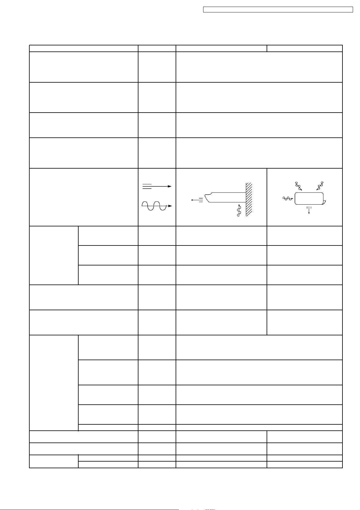
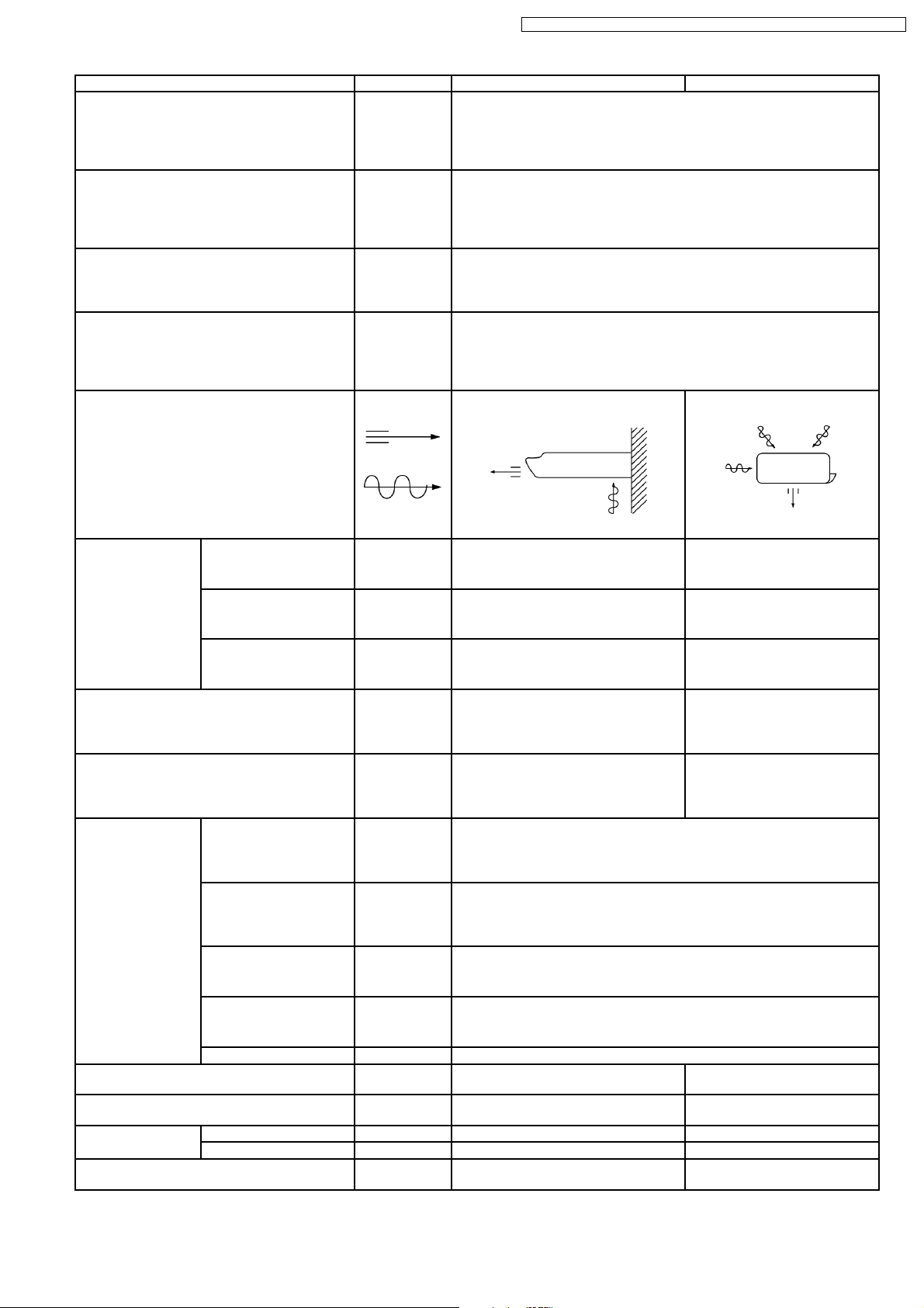
11.1.1. Relationship between the condition of the air conditioner and pressure and
electric current
Cooling Mode Heating Mode
Condition of the air
conditoner Low Pressure High Pressure Electric current
during operation
Insufficient refrigerant
(gas leakage)
Clogged capillary tube
or Strainer
Short circuit in the
indoor unit
Heat radiation
deficiency of the
outdoor unit
Low Pressure High Pressure Electric current
during operation
Inefficient compression
•
Carry out the measurements of pressure, electric current, and temperature fifteen minutes after an operation is started.
11.1.2. Diagnosis methods of a malfunction of a compressor and 4-way valve
Nature of fault Symptom
•
Electric current during operation becomes approximately 20% lower than the normal value.
Insufficient compressing of a compressor
Locked compressor
•
The discharge tube of the compressor becomes abnormally hot (normally 70 to 90°C).
•
The difference between high pressure and low pressure becomes almost zero.
•
Electric current reaches a high level abnormally, and the value exceeds the limit of an
ammeter. In some cases, a breaker turns off.
•
The compressor is a humming sound.
Insufficient switches of the 4-way valve
•
Electric current during operation becomes approximately 80% lower than the normal value.
•
The temperature different between from the discharge tube to the 4-way valve and from
suction tube to the 4-way valve becomes almost zero.
38
Page 39

12 Technical Data
CS-A12ATP5 CU-A12ATP5 / CS-A18ATP5 CU-A18ATPT5 / CS-A24ATP5 CU-A24ATPT5
39
Page 40

CS-A12ATP5 CU-A12ATP5 / CS-A18ATP5 CU-A18ATPT5 / CS-A24ATP5 CU-A24ATPT5
240V Outdoor Temp. (°C)
Indoor wet
bulb temp.
TC SHC IP TC SHC IP TC SHC IP TC SHC IP
30 35 40 46
17.0°C 3.37 2.56 1.19 3.15 2.45 1.28 2.93 2.36 1.37 2.67 2.24 1.48
19.0°C 3.40 1.30
19.5°C 3.70 2.68 1.21 3.46 2.57 1.31 3.22 2.48 1.40 2.93 2.36 1.51
22.0°C 4.04 2.78 1.24 3.77 2.67 1.33 3.51 2.58 1.42 3.19 2.46 1.53
230V Outdoor Temp. (°C)
Indoor wet
bulb temp.
TC SHC IP TC SHC IP TC SHC IP TC SHC IP
30 35 40 46
17.0°C 3.32 2.52 1.17 3.11 2.42 1.26 2.89 2.32 1.35 2.63 2.21 1.46
19.0°C 3.35 1.28
19.5°C 3.65 2.64 1.19 3.41 2.53 1.29 3.17 2.44 1.37 2.88 2.32 1.48
22.0°C 3.98 2.74 1.22 3.72 2.63 1.31 3.46 2.54 1.40 3.14 2.42 1.51
220V Outdoor Temp. (°C)
Indoor wet
bulb temp.
TC SHC IP TC SHC IP TC SHC IP TC SHC IP
30 35 40 46
17.0°C 3.32 2.52 1.16 3.11 2.42 1.25 2.89 2.32 1.34 2.63 2.21 1.44
19.0°C 3.35 1.27
19.5°C 3.65 2.64 1.18 3.41 2.53 1.28 3.17 2.44 1.36 2.88 2.32 1.47
22.0°C 3.98 2.74 1.21 3.72 2.63 1.30 3.46 2.54 1.39 3.14 2.42 1.50
240V Outdoor Temp. (°C)
Indoor wet
bulb temp.
TC SHC IP TC SHC IP TC SHC IP TC SHC IP
30 35 40 46
17.0°C 3.37 2.56 1.19 3.15 2.45 1.28 2.93 2.36 1.37 2.67 2.24 1.48
19.0°C 3.40 1.30
19.5°C 3.70 2.68 1.21 3.46 2.57 1.31 3.22 2.48 1.40 2.93 2.36 1.51
22.0°C 4.04 2.78 1.24 3.77 2.67 1.33 3.51 2.58 1.42 3.19 2.46 1.53
230V Outdoor Temp. (°C)
Indoor wet
bulb temp.
TC SHC IP TC SHC IP TC SHC IP TC SHC IP
30 35 40 46
17.0°C 5.01 3.80 1.95 4.68 3.64 2.10 4.35 3.50 2.25 3.96 3.33 2.42
19.0°C 5.05 2.13
19.5°C 5.50 3.98 1.99 5.14 3.82 2.14 4.78 3.68 2.29 4.35 3.50 2.47
22.0°C 5.99 4.12 2.02 5.60 3.97 2.18 5.21 3.83 2.33 4.74 3.65 2.51
220V Outdoor Temp. (°C)
Indoor wet
bulb temp.
TC SHC IP TC SHC IP TC SHC IP TC SHC IP
30 35 40 46
17.0°C 5.01 3.80 1.91 4.68 3.64 2.05 4.35 3.50 2.19 3.96 3.33 2.36
19.0°C 5.05 2.08
19.5°C 5.50 3.98 1.94 5.14 3.82 2.09 4.78 3.68 2.23 4.35 3.50 2.41
22.0°C 5.99 4.12 1.98 5.60 3.97 2.13 5.21 3.83 2.27 4.74 3.65 2.45
40
Page 41

CS-A12ATP5 CU-A12ATP5 / CS-A18ATP5 CU-A18ATPT5 / CS-A24ATP5 CU-A24ATPT5
240V Outdoor Temp. (°C)
Indoor wet
bulb temp.
TC SHC IP TC SHC IP TC SHC IP TC SHC IP
30 35 40 46
17.0°C 3.37 2.56 1.19 3.15 2.45 1.28 2.93 2.36 1.37 2.67 2.24 1.48
19.0°C 3.40 1.30
19.5°C 3.70 2.68 1.21 3.46 2.57 1.31 3.22 2.48 1.40 2.93 2.36 1.51
22.0°C 4.04 2.78 1.24 3.77 2.67 1.33 3.51 2.58 1.42 3.19 2.46 1.53
230V Outdoor Temp. (°C)
Indoor wet
bulb temp.
TC SHC IP TC SHC IP TC SHC IP TC SHC IP
30 35 40 46
17.0°C 6.00 4.55 2.56 5.61 4.36 2.76 5.22 4.19 2.95 4.74 3.98 3.18
19.0°C 6.05 2.80
19.5°C 6.59 4.76 2.61 6.16 4.58 2.81 5.73 4.41 3.01 5.21 4.19 3.24
22.0°C 7.18 4.94 2.66 6.71 4.75 2.86 6.24 4.58 3.06 5.67 4.37 3.30
220V Outdoor Temp. (°C)
Indoor wet
bulb temp.
TC SHC IP TC SHC IP TC SHC IP TC SHC IP
30 35 40 46
17.0°C 5.95 4.51 2.52 5.56 4.33 2.71 5.17 4.16 2.90 4.70 3.95 3.13
19.0°C 6.00 2.75
19.5°C 6.53 4.72 2.57 6.11 4.54 2.76 5.68 4.37 2.95 5.17 4.16 3.18
22.0°C 7.12 4.90 2.61 6.65 4.71 2.81 6.19 4.54 3.01 5.63 4.33 3.24
TC - Total Cooling Capacity (kW) Indoor 27°C/19°C
SHC - Sensible Heat Capacity (kW) Outdoor 35°C/24°C
IP - Input Power (kW)
41
Page 42

CS-A12ATP5 CU-A12ATP5 / CS-A18ATP5 CU-A18ATPT5 / CS-A24ATP5 CU-A24ATPT5
13 Exploded View
42
Page 43

CS-A12ATP5 CU-A12ATP5 / CS-A18ATP5 CU-A18ATPT5 / CS-A24ATP5 CU-A24ATPT5
14 Replacement Parts List
<Model: CS-A12ATP / CS-A18ATP / CS-A24ATP>
REF. NO. PART NAME & DESCRIPTION QTY. CS-A12ATP5 CS-A18ATP5 CS-C24ATP5
1 BASE ASS’Y 1 CWD52K195B
2 PARTICULAR PLATE FOR BASE 1 CWD90811
3 PARTICULAR PIECE 2 CWD93592
4 PARTICULAR PLATE 1 CWD90821
5 FAN MOTOR BRACKET (BOTTOM) 1 CWD54152
6 FAN MOTOR 1 CWA921094 CWA921092
7 FAN MOTOR BRACKET (UPPER) 1 CWD54153
8 BLOWER WHEEL ASS’Y 2 CWH01K094
9 AIR GUIDER B.W. (BOTTOM) 2 CWD32104
10 AIR GUIDER B.W. (UPPER) 2 CWD32103
12 CONTROL BOARD ASS’Y 1 CWH10K330
13 CAPACITOR FOR FAN MOTOR 1 CWA31342
(1.2MF/400VAC)
14 TERMINAL BOARD (BIG) 1 CWA28K1030
15 TRANSFORMER 1 CWA40C192
16 P.C. BOARD-MAIN 1 CWA742727
17 SENSOR ASS’Y (INTAKE AIR) 1 CWA50C447
18 SENSOR - EVAPORATOR PIPE 1 CWA50C534 CWA50C533
19 EVAPORATOR 1 CWB30428 CWB30429 CWB30430
20 TUBE ASS’Y (LIQUID SIDE) 1 CWT01494 CWT01479
21 FLARE NUT 1 CWH6002140 (1/4”)
22 TUBE ASS’Y (GAS SIDE) 1 CWT01495 CWT01480 CWT01481
23 FLARE NUT 1 CWT25007 (1/2”)
24 TAP DRAIN TRAY 1 CWH4612103
25 DRAIN PAN ASS’Y 1 CWH40K025
26 DISCHARGE GRILLE COMPLETE 1 CWE20C2127
27 DISCHARGE GRILLE 1 CWE20C135
28 VANE - AIR SWING 1 CWE24233A
29 VANE 12 CWE24234A
30 AIR SWING MOTOR 1 CWA98K059
31 INDICATOR 1 CWE391051
32 RECEIVER COMPLETE 1 CWD76C003
34 CABINET FRONT PLATE 1 CWE06074A
35 CABINET RIGHT SIDE PLATE 1 CWE04109
36 CABINET LEFT SIDE PLATE 1 CWE04110
37 CONTROL BOARD COVER 1 CWH13292 - 38 INTAKE GRILLE 1 CWE22C052
39 HOLDER - INTAKE GRILLE (RIGHT) 1 CWD93594
40 HOLDER - INTAKE GRILLE (UPPER) 1 CWD93593
41 HOLDER - INTAKE GRILLE (LEFT) 1 CWD93607
42 AIR FILTER 2 CWD00112
43 REMOTE CONTROL COMPLETE 1 CWA75C2208
44 POWER SUPPLY CORD 1 CWA20C2223 CWA20C2221 CWA20C2222
← ←
← ←
← ←
← ←
← ←
← ←
← ←
← ←
← ←
← ←
CWA31615
(1.2MF/450VAC)
← ←
← ←
← ←
← ←
← ←
←
← ←
← ←
← ←
← ←
← ←
← ←
← ←
← ←
← ←
← ←
← ←
← ←
← ←
← ←
← ←
← ←
← ←
← ←
←
←
←
←
CWT25004 (5/8”)
(Note)
All parts are supplied from MACC, Malaysia (Vendor Code: 061).
•
43
Page 44

CS-A12ATP5 CU-A12ATP5 / CS-A18ATP5 CU-A18ATPT5 / CS-A24ATP5 CU-A24ATPT5
15 Exploded View
44
Page 45

CS-A12ATP5 CU-A12ATP5 / CS-A18ATP5 CU-A18ATPT5 / CS-A24ATP5 CU-A24ATPT5
16 Replacement Parts List
<Model: CU-A12ATP / CU-A18ATPT / CU-A24ATPT>
REF. NO. PART NAME & DESCRIPTION QTY. CU-A12ATP5 CU-A28ATPT5 CU-A24ATPT5
1 CHASSY ASS’Y 1 CWD50K550A CWD50K514B
2 SOUND PROOF BOARD 1 CWH15214 CWH15223
3 FAN MOTOR BRACKET 1 CWD54155 CWD54145
4 SUPPORTOR - F.M. BRACKET (LEFT) 1 - CWD90835
5 SUPPORTOR - F.M. BRACKET (RIGHT) 1 - CWD90836
6 FAN MOTOR 1 CWA951151 CWA921095 CWA921093
7 PROPELLER FAN 1 CWH03K002 CWH00K049
8 NUT - P. FAN 1 CWH56053 CWH56060
9 COMPRESSOR 1 2KS224D5AA02 2JS350D3DA02 2JS442D3BA01
10 PACKING - COMP. MOUNT. 1/2 CWB81047 CWB81043 (2)
11 BUSHING - COMP. MOUNT. 3 CWH50055
12 NUT - COMP. MOUNT. 3 CWH4582065
13 CONDENSER 1 CWBDCC004 CWB32C177
14 RECEIVER 1 CWB14010 CWB14011
15 HOLDER - COUPLING 1 CWH35123A CWH35113B CWH35114B
16 GUIDER - COMP. 1 - CWD90830
17 3-WAY VALVE (LIQUID SIDE) 1 CWB01380 CWB01463
18 FLARE NUT 1 CWH6002140 (1/4”)
19 TUBE ASS’Y (STRAINER, CAPILLARY) 1 CWB11025 CWT01531
20 TUBE ASS’Y (CHECK VALVE, CAPILLARY) 1 CWT00C721 - 21 3-WAY VALVE (GAS SIDE) 1 CWB01379 CWB01364 CWB01377
22 4-WAY VALVE 1 CWB00003
23 4-WAY COIL COMPLETE 1 CWA43C2085 CWA43C2084
24 FLARE NUT 1 CWT25007 (1/2”)
25 NUT - TERMINAL COVER 1 CWH7080300
26 TERMINAL COVER - COMP. 1 CWH171011 CWH171012
29 CONTROL BOARD 1 CWH102127 CWH10K331
30 CAPACITOR - F. MOTOR 1 CWA31602
31 CAPACITOR - COMP. 1 CWA312076
32 ELECTRO MAGNETIC SWITCH 2 CWA00059
33 ELECTRO MAGNETIC SWITCH 1 - CWA00111
34 PRESSURE SWITCH 2 CWA10046
35 PRESSURE SWITCH 2 CWA10047
36 HOLDER - CAPACITOR 1 CWA30057
37 THERMOSTAT 1 - CWA15129
38 TERMINAL BOARD 1 CWA28K1021
39 TERMINAL BOARD (SMALL) 1 - CWH4711012
40 HOLDER - SENSOR 1 - CWH32002
41 CABINET ASS’Y 1 CWE00K240B - 42 CABINET FRONT PLATE 1 CWE06C050B CWE06K024B
43 CABINET REAR PLATE 1 - CWE02096B
44 CABINET FRONT PLATE 1 - CWE06075B
45 CABINET SIDE PLATE 1 - CWE04111B
46 CABINET TOP PLATE 1 - CWE03101B
47 CONTROL BOARD COVER 1 CWH13C286 CWH13021D
48 HANDLE 1/2 CWE16037C (1) CWE16000E (2)
49 SCREW - FAN MOTOR BRACKET 4/6 CWH4580399 (4) CWH55101 (6)
50 SCREW - SUPPORTOR 10 - CWH4580345
51 SCREW - FAN MOTOR MOUNT 2/4 CWH55027 (2) CWH55252 (4)
52 HOLDER - F.M. LEAD WIRES 1 CWH31043 CWH31043
55 SOUND PROOF MATERIAL (COMP.) 1 - CWG30561
56 SOUND PROOF MATERIAL 1 CWG30596 - 58 OPERATING INSTRUCTIONS 1 CWF563417
59 INSTALLATION INSTRUCTIONS 1 CWF612226
(1.2MF, 400V)
(30MF, 370V)
CWF612227
CWF612228
← ←
← ←
← ←
← ←
←
← ←
DS371356CPNA
(3.5MF, 400VAC)
CWA312077
(35MF, 370VAC)
← ←
← ←
← ←
←
← ←
← ←
← ←
←
←
←
←
←
←
←
←
←
←
←
←
←
←
CWT25004 (5/8”)
←
←
←
CWA312079
(45MF, 370VAC)
←
CWH30060
←
←
←
←
←
←
←
←
←
←
←
←
←
←
←
(Note)
All parts are supplied from MACC, Malaysia (Vendor Code: 061).
•
45
Page 46

CS-A12ATP5 CU-A12ATP5 / CS-A18ATP5 CU-A18ATPT5 / CS-A24ATP5 CU-A24ATPT5
17 Electronic Parts List
CWA74314
SYMBOL DESCRIPTION & NAME PART NO.
BZ BUZZER A48039
D1, D2, D3, D4, D5 DIODE A54MA165TA5
D6 DIODE A54RA15-01KB
DB1 DIODE BRIDGE A54CS1VB20E
FUSE FUSE XBA2C20TR0
IC1 INTEGRATED CIRCUIT A52D7533U313
IC2 INTEGRATED CIRCUIT A54MN1551ABA
IC3 INTEGRATED CIRCUIT A52MPC393C
IC4 INTEGRATED CIRCUIT A52MPA2003C
IC5 INTEGRATED CIRCUIT A52M54566P
IC6 INTEGRATED CIRCUIT A52C057
IC7 INTEGRATED CIRCUIT A52LQT50.5X1
IC8 INTEGRATED CIRCUIT A52C057
PC1 PHOTO COUPLER A52LP620-GB
Q1 TRANSISTOR A55DTD1234EST
Q2, Q3 TRANSISTOR A55C1740STPQ
Q4 TRANSISTOR A55DTC123YST
RY-C RELAY A00042
RY-H, RY-M, RY-L, RY-HOT RELAY A00084
X1 RESONATOR A45CSB400P19
X2 RESONATOR A45ST4.0MGWT
ZD1 ZENAR DIODE A54D6.2EL2TB
ZNR1 ZNR A54C057
(Note)
•
All parts are supplied from MACC, Malaysia (Vendor Code: 086)
46
Page 47

18 Electronic Circuit Diagram
• CS-C12ATP / CU-C12ATP
SCHEMATIC DIAGRAM 1/3
RY-C
CS-A12ATP5 CU-A12ATP5 / CS-A18ATP5 CU-A18ATPT5 / CS-A24ATP5 CU-A24ATPT5
TF
(VH-2)
T
L
BLACKTBLACK
P
CN-T
MAGNETIC RELAY
8
5
BLUE
C
L
PRESSURE SWITCH
L
BLUE
C
H
PRESSURE SWITCH
7
3
4
WHITE
WHITE
BLUE
BLACK
CAPASITOR
BLACK
MAGNETIC RELAY
ORANGE
BLACK
8
3
4
YELLOW
BLUEBLUE
3421
3421
RED
COIL
7
5
6
Y/G
REVERSING
VALVE
RED
YELLOW
FAN MOTOR
C-FM
YELLOW
COMPRESSOR
BLUE
WHITE
RED
RY-HOT
BLUE
GRY
GRY
(VH-3)
GREEN
CN-C
O.L.P.
YELLOW
BLUE
CAPACITOR
ZNR1
FUSE
ERZTCEAK471
2A
R42
1W
33.0K
R43
1W
33.0K
RY-H
CR1
CR2
ECQJ0186X
ECQJ0187X
1
1
3 3 53
FAN
MOTOR
RED
PC1
TLP620-GB
1
C24
0.01µ
2 3
RY-M
RY-L
(VH-5)
CN-FM
Remote Control No.
4
GREEN
ELECTRONIC
CIRCUIT
0
1
2
3
DB1
S1VB10
15
IC8
TA78DL12S
12V
I
R39
1W
91Ω
R102
1.5K
R41
10.0K
INTAKE AIR TEMP
SENSOR
(15K.3950)
PIPE TEMP
SENSOR
(20K.3950)
DISCHARGE AIR TEMP
SENSOR
(15K.3950)
Jumper Wire
C21
25V
3300µ
12
O
G
C22
25V
470µ
Rx
——
16 K
6.2 KΩ
C23
25V
10µ
RY-C
D6
ERA15-01
RY-HOT
RY-H
RY-M
RY-L
Fig.1
Fig.1
Fig.1
R40
1.5K
R30 4.7K
(NH-2) BLUE
PUMP
2
1
2
1
3
4
5
6
CN-TH
(NH-6) YELLOW
R34
15.0K
R35
5.9K
47
Page 48

CS-A12ATP5 CU-A12ATP5 / CS-A18ATP5 CU-A18ATPT5 / CS-A24ATP5 CU-A24ATPT5
SCHEMATIC DIAGRAM 2/3
IC6
AN78M05
REGULATOR
15 5
5V
C14
IO
25V
G
10µ
SU SU
IC7
LQT50.5X1
1
2
3
Q4
UN4224
RY-C
DRIVE
0
11 6
IC4
µPA2003C
13 4
4
15 2
4
C15
10V
22µ
SU
R36
10.0K
C16
10V
22µ
SU
12 5
14 3
16 1
R38
1W
1.2KΩ
C13
10V
22µ
R29
(50.5Hz)
1.0K
C12
0.01µ
C19
0.01µ
0
5
9
4
8
4
4
4
RX
R31
10.0K
C11
0.01µ
R37
R33
10.0K
10.0K
3
C18
2
1000P
C17
10V22µ
SU
IC3
R24
R25
2.8K
20.0K
5
6
C9
1000P
H
IC3
R22
18.7K
µPD7533CU221
P43 VSS
1
5
P42
2
DISPLAY
0
OUTPUT
P41
3
0
P40
4
R1 1K
5
P22
P21
6
BUZZER
5
P73
COMP
7
5 (0)
P72
8
4WAY
VALVE
9
P71
5 (0)
P70
10
0 (5)
P33
11
FAN
MOTOR
0
P32
DRIVE
12
0
P31
13
0
P30
14
0
AVSS
15
ANALOG GND
AN3
16
AN2
17
AN1
18
0
AN0
19
5
VAREF
20
5
VDD
21
1
IC3
µPC393C
INTAKE AIR TEMP
PIPE
TEMP
REMOTE CONTROL
NO. DETECTION
AIRFLOW POWER
POWER
Fig. 2
Fig. 2
C10
10V
100µ
SU
8
4
R32
158K
R23
15.8K
R21
13.7K
IC3
µPC393C
OSC
IC1
7
R19
1.0K
R20
10.0K
MICROCOMPUTER
GND
400KHz
OSC
RESET
REMOTE
CONTROL
COMMAND
INPUT
CLOCK
TIME
SHORTEN
DIVSEL
RESET
INTO
BZ
SCK
P03
P10
P11
P12
P13
P60
P61
P62
P63
P50
P51
P52
P53
CL2
CL1
S0
Q3
2SC1740S
BUZZER DRIVE
0
42
41
40
39
38
2.3
37
2.2
36
5
35
0
34
33
0
32
0
31
2.5
30
0
29
0
28
R13 1.0K
0
27
0
26
0
R14 10.0K
25
R15 10.0K
5
24
5
R16 10.0K
23
R17 10.0K
0
22
R18
10.0K
RA1
10K x 4
R12
1.0K
C8
10V22µ
1 2 3 4
R26 300Ω
R27 300Ω
RA2
10K x 10
X1
CSB400P
C6
220PC5220P
C7
0.01µ
(NH-2) WHITE
C3
R10
0.01µ
4.7K
R11
1.0K
TEST
21
C1
0.01µ
R2
10K
C4
6.3V 330µ
Fig. 2
ZD1
RD6.2EL2
SU
IC2
VDD
1
SB1
2
SB0
3
P40/RBI
4
5
P41/IRQ
P41/IC1
6
P00
7
8
P01
P02
9
P03
10
11
P10
P11
12
P12
13
P13
14
R7
4.7K
R8
10.0KR9510.0K
MN1551ABA
POWER
DISCHARGE
AIR TEMP.
FORCED
CLOSE
AIR-FLOW
DIRECTION
C20
50V1µ
SU
GND
4MHz
OSC
RESET
DISPLAY
OUT
STEPPING
MOTOR
DRIVE
D5
MA165
TA-5
R5
R6
47.0K
2.0K
Q2
2SC1740S
RESET SIGNAL GENERATION
VSS
OSC1
OSC2
RSC
SYNC
28
27
26
25
24
P51
P50
23
P33
22
P32
21
P31
20
P30
19
P23
18
17
P22
P21
16
P20
15
1
R
1K
PD1
PN313B
C1
16V10µ
K
48
Page 49

SCHEMATIC DIAGRAM 3/3
CS-A12ATP5 CU-A12ATP5 / CS-A18ATP5 CU-A18ATPT5 / CS-A24ATP5 CU-A24ATPT5
R3
510.0K
2415
IC5
M54588P
STEPPING MOTOR
DRIVE
R4
10.0K
Q1
UN4212
X2
CST4.0OMGT
9
116
3614
13
11
8
D1 D2 D3 D4
MA165
X4
TA-5
GND
(XH-4)
BLUE
CN-DISP
1
2
3
4
3
4
5
6
2
1
CN-STM
(NH-6) WHITE
(XH-4)
BLUE
CN-DISP
1
2
3
4
STEPPING MOTOR
DISPLAY
RED
ORANGE
OPERATION
TIMER
AUTO
Heat Exchanger Temp.
Intake Air Sensor
DISCHARGE AIR TEMP SENSOR
Outlet Air / Inlet Air /
Heat Exchanger Temp. Data
(XH-4) GREEN
34
112
CN-RCV
(XH-4) GREEN
3
24
CN-RCV
4
R
K
.1
5
R
10.0
8 1
6 5 2 3
R3
10Ω
C4
16V10µ
K
4300P
ECQP
4
IC
µPC1475HA
C5
4300P
ECQP
L1
CWA43053
K
C2
2
L2
CWA43053
C3
16V
10µ
K
7 9
C6
0.033µ
ECQP
C7
6.3V
47µ
K
C8
10000P
J1
SW
J1
RECEIVER
FORCED
OPERATION
SWITCH
010203040506070
49
Page 50

CS-A12ATP5 CU-A12ATP5 / CS-A18ATP5 CU-A18ATPT5 / CS-A24ATP5 CU-A24ATPT5
• CS-A18ATP / CU-A18ATPT
• CS-A24ATP / CU-A24ATPT
SCHEMATIC DIAGRAM 1/3
RY-C
TF
(VH-2)
T
L
BLACKTBLACK
P
CN-T
MAGNETIC RELAY
8
5
WHITE
BLUE
C
L
PRESSURE SWITCH
L
BLUE
C
H
PRESSURE SWITCH
WHITE
BLUE
BLUE
7
3
4
BROWN
BLACK
ORANGE
BLACK
YELLOW
WHITE
3421
3421
BLACK
MAGNETIC RELAY
8
3
4
YELLOW
MAGNETIC RELAY
BLUE
BROWN
BROWN
2
C-FM
WHITE
RED
RY-HOT
BLUE
GRY
GRY
(VH-3)
GREEN
1
3 3 53
CN-C
CR1
ECQJ0186X
MOTOR
FUSE
2A
FAN
1
CR2
ECQJ0187X
ZNR1
ERZTCEAK471
R42
1W
33.0K
C24
0.01µ
R43
1W
33.0K
RY-H
PC1
TLP620-GB
1
2 3
RY-M
RY-L
(VH-5)
GREEN
CN-FM
DB1
S1VB10
15
C21
IC8
TA78DL12S
I
R39
1W
91Ω
12V
G
25V
3300µ
C22
25V
470µ
12
O
C23
25V
10µ
RY-C
D6
ERA15-01
RY-HOT
RY-H
R40
1.5K
4
R102
1.5K
Y/G
RY-M
YELLOW
COIL
REVERSING
VALVE
RED
7
5
YELLOW
6
7
8
3
5
1
4
6
2
COMPRESSOR
BLUE
FAN
MOTOR
ORANGE
YELLOW
BLUE
CAPASITOR
WHITE
RED
H
RED
CAPACITOR
BROWN
1
BROWN
L
C
THERMOSTAT
BLUE
Remote Control No.
R41
10.0K
ELECTRONIC
CIRCUIT
INTAKE AIR TEMP
SENSOR
(15K.3950)
PIPE TEMP
SENSOR
(20K.3950)
DISCHARGE AIR TEMP
SENSOR
(15K.3950)
0
1
2
3
Jumper Wire
Rx
——
16 K
6.2 KΩ
RY-L
Fig.1
Fig.1
Fig.1
R30 4.7K
(NH-2) BLUE
PUMP
2
1
2
1
3
4
5
6
CN-TH
(NH-6) YELLOW
R34
15.0K
R35
5.9K
50
Page 51

SCHEMATIC DIAGRAM 2/3
N
R38
1W
IC6
0
C16
10V
22µ
SU
5V
G
R29
1.0K
1
2
3
0
11 6
12 5
14 3
16 1
1.2KΩ
C13
10V
22µ
(50.5Hz)
C12
0.01µ
C19
0.01µ
5
R1 1K
9
4
8
4
4
4
Fig. 2
Fig. 2
RX
R31
10.0K
C10
C11
10V
0.01µ
100µ
R37
R33
10.0K
10.0K
3
8
C18
IC3
2
1000P
4
C17
10V22µ
SU
AN78M05
REGULATOR
15 5
C14
IO
25V
10µ
SU SU
IC7
LQT50.5X1
Q4
UN4224
RY-C
DRIVE
IC4
µPA2003C
13 4
4
15 2
4
C15
10V
22µ
SU
R36
10.0K
R24
R25
20.0K
R22
18.7K
SU
5 (0)
5 (0)
0 (5)
R32
158K
2.8K
1
5
2
0
3
0
4
5
6
5
7
8
9
10
11
0
12
0
13
0
14
0
15
16
17
18
0
19
5
20
5
21
1
IC3
µPC393C
R23
5
15.8K
IC3
6
R21
13.7K
C9
1000P
IC3
H
µPC393C
OSC
IC1
µPD7533CU221
P43 VSS
P42
DISPLAY
OUTPUT
P41
P40
P22
P21
BUZZER
P73
COMP
P72
4WAY
VALVE
P71
P70
P33
FAN
MOTOR
P32
DRIVE
P31
P30
AVSS
ANALOG GND
AN3
INTAKE AIR TEMP
AN2
PIPE
TEMP
AN1
REMOTE CONTROL
AN0
NO. DETECTION
VAREF
AIRFLOW POWER
VDD
POWER
R19
1.0K
7
R20
10.0K
MICROCOMPUTER
GND
400KHz
OSC
RESET
REMOTE
CONTROL
COMMAND
INPUT
CLOCK
TIME
SHORTEN
BZ
CL2
CL1
DIVSEL
RESET
INTO
SCK
P03
P10
P11
P12
P13
P60
P61
P62
P63
Q3
2SC1740S
BUZZER DRIVE
42
41
P50
P51
40
P52
39
P53
38
37
36
35
34
33
32
31
S0
30
29
28
27
26
25
24
23
22
0
2.3
2.2
5
0
0
0
2.5
0
0
0
0
0
5
5
0
R13 1.0K
R14 10.0K
R15 10.0K
R16 10.0K
R17 10.0K
CS-A12ATP5 CU-A12ATP5 / CS-A18ATP5 CU-A18ATPT5 / CS-A24ATP5 CU-A24ATPT5
1 2 3 4
R26 300Ω
R18
10.0K
RA1
10K x 4
R12
1.0K
C8
10V22µ
R27 300Ω
RA2
10K x 10
X1
CSB400P
C6
220PC5220P
C3
0.01µ
C7
0.01µ
TEST
21
(NH-2) WHITE
R10
4.7K
R11
1.0K
C1
0.01µ
R2
10K
C4
6.3V 330µ
Fig. 2
ZD1
RD6.2EL2
SU
IC2
VDD
1
SB1
2
SB0
3
P40/RBI
4
5
P41/IRQ
P41/IC1
6
P00
7
8
P01
P02
9
P03
10
11
P10
P11
12
P12
13
P13
14
R7
4.7K
R8
10.0KR9510.0K
MN1551ABA
POWER
DISCHARGE
AIR TEMP.
FORCED
CLOSE
AIR-FLOW
DIRECTION
C20
50V1µ
SU
GND
4MHz
OSC
RESET
DISPLAY
OUT
STEPPING
MOTOR
DRIVE
D5
R6
MA165
2.0K
TA-5
Q2
2SC1740S
RESET SIGNAL GENERATIO
R5
47.0K
VSS
OSC1
OSC2
RSC
SYNC
28
27
26
25
24
P51
P50
23
P33
22
P32
21
P31
20
P30
19
P23
18
17
P22
P21
16
P20
15
1
R
1K
PD1
PN313B
C1
16V10µ
K
51
Page 52

CS-A12ATP5 CU-A12ATP5 / CS-A18ATP5 CU-A18ATPT5 / CS-A24ATP5 CU-A24ATPT5
SCHEMATIC DIAGRAM 3/3
R3
510.0K
2415
IC5
M54588P
STEPPING MOTOR
DRIVE
R4
10.0K
Q1
UN4212
X2
CST4.0OMGT
9
116
3614
13
11
8
D1 D2 D3 D4
MA165
X4
TA-5
GND
(XH-4)
BLUE
CN-DISP
1
2
3
4
3
4
5
6
2
1
CN-STM
(NH-6) WHITE
DISPLAY
(XH-4)
BLUE
CN-DISP
1
2
3
4
STEPPING MOTOR
RED
ORANGE
OPERATION
TIMER
AUTO
Heat Exchanger Temp.
Intake Air Sensor
DISCHARGE AIR TEMP SENSOR
Outlet Air / Inlet Air /
Heat Exchanger Temp. Data
24
C2
4300P
ECQP
IC
µPC1475HA
C5
4300P
ECQP
(XH-4) GREEN
112
CN-RCV
(XH-4) GREEN
CN-RCV
L1
CWA43053
L2
CWA43053
C3
16V
10µ
K
7 9
34
3
R4
K
.1
5
2
R
K
10.0
4
8 1
6 5 2 3
R3
10Ω
C4
16V10µ
K
C6
0.033µ
ECQP
C7
6.3V
47µ
K
C8
10000P
J1
SW
J1
RECEIVER
FORCED
OPERATION
SWITCH
0 10203040506070
52
Page 53

How to use electronic circuit diagram
CS-A12ATP5 CU-A12ATP5 / CS-A18ATP5 CU-A18ATPT5 / CS-A24ATP5 CU-A24ATPT5
TIMER TABLE
Test Mode
Name Time (When test point
Short-circuited)
Time Delay Safety Control 2 min. 58 sec. 0 sec.
Circuit Protection Control 30 sec. 0 sec.
Starting Current Control 1.6 sec. 0 sec.
Automatic Restarting Control 7 min. 7 min. Sleep Mode
5 min. 5 min.
12 hrs. 12 min.
11 hrs. 11 min.
10 hrs. 10 min.
9 hrs. 9 min.
8 hrs. 8 min.
7 hrs. 7 min.
Timer 6 hrs. 6 min.
5 hrs. 5 min.
4 hrs. 4 min.
3 hrs. 4 min.
2 hrs. 2 min.
1hr. 1 min.
10 min. 10 sec. ON Time
Sleep Mode Auto Control 20 min. 20 sec. OFF Time
5 hrs. 5 min.
4 sec. 4 sec. ON/OFF
Soft Dry 10 min. 1 min. ON
6 min. 6 min. OFF
Anti Freezing Control 3 min. 18 sec.
Remarks
53
Page 54

CS-A12ATP5 CU-A12ATP5 / CS-A18ATP5 CU-A18ATPT5 / CS-A24ATP5 CU-A24ATPT5
18.1. REMOTE CONTROL
54
Page 55

18.2. PRINT PATTERN
INDOOR UNIT PRINTED CIRCUIT BOARD
CS-A12ATP5 CU-A12ATP5 / CS-A18ATP5 CU-A18ATPT5 / CS-A24ATP5 CU-A24ATPT5
55
Page 56

CS-A12ATP5 CU-A12ATP5 / CS-A18ATP5 CU-A18ATPT5 / CS-A24ATP5 CU-A24ATPT5
56
[MACC] Printed in Malaysia
 Loading...