

Page 1
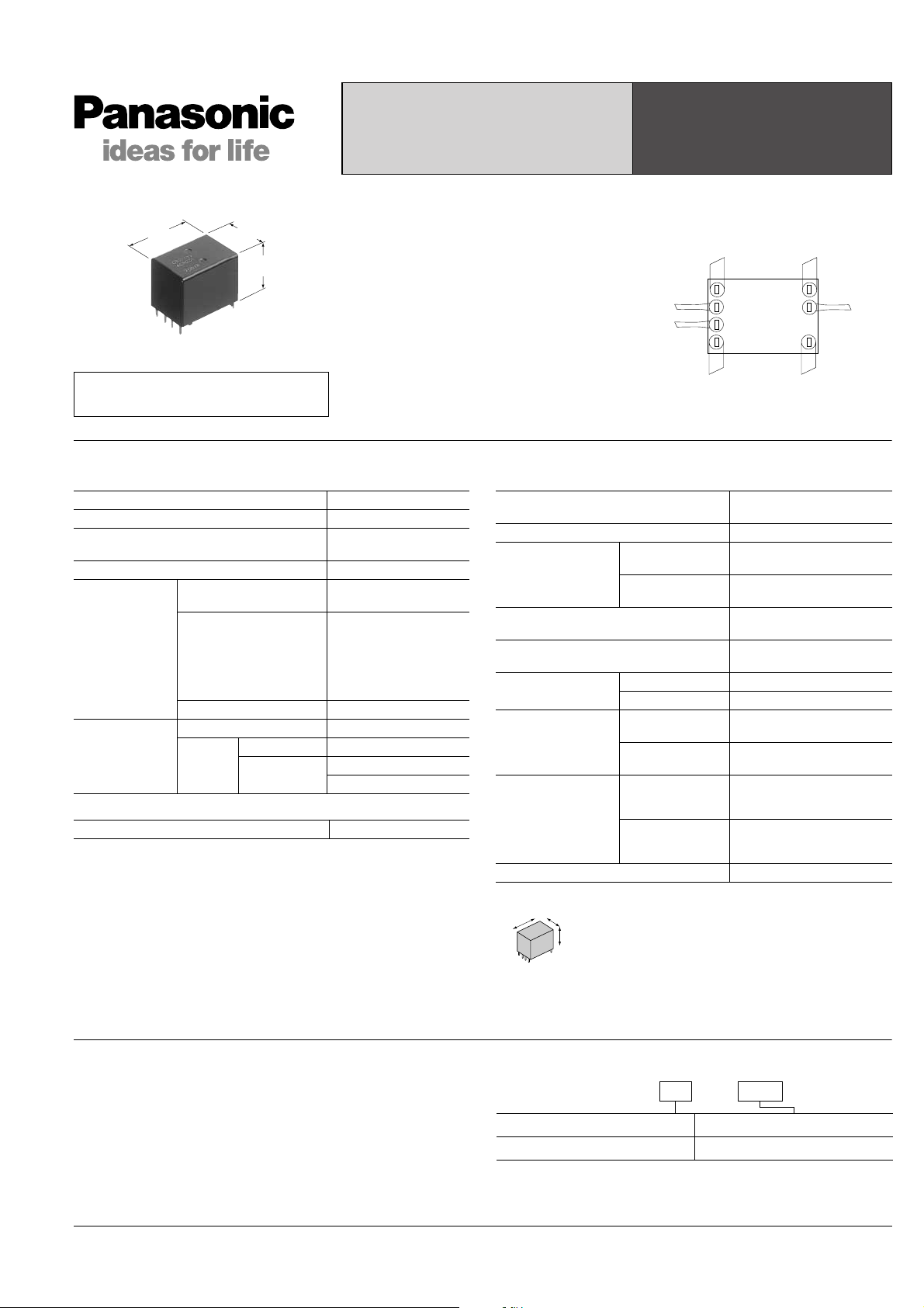
TWIN POWER SILENT
AUTOMOTIVE RELAY
CR
CR RELAYS
24.6
.969
17.0
.669
18.5
.728
FEATURES
• Silent
Noise has been reduced by
approximately 20 dB, using our own
silencing design.
• Twin (1 Form C × 2)
mm inch
Forward/reverse motor control is possible
with a single relay.
• Sealed construction
RoHS Directive compatibility information
• Simple footprint enable ease of PC
http://www.nais-e.com/
SPECIFICATIONS
Contact
Arrangement 1 Form C × 2
Contact material Ag alloy (Cadmium free)
Initial contact resistance (Initial)
(By voltage drop 6 V DC 1A)
Contact voltage drop Max. 0.2V (at 10 A)
Nominal switching
capacity
Rating
Max. carrying current
Min. switching capacity
Mechanical (at 120 cpm) Min. 10
Expected life
(min. operations)
Electrical
Resistive load Min. 10
Motor load
Coil
Nominal operating power 640 mW
#1 This value can change due to the switching frequency, environmental conditions,
and desired reliability level, therefore it is recommended to check this with the
actual load.
Remarks
*1At nominal switching capacity, operating frequency: 1s ON, 9s OFF
2
N.O.: at 5 A (steady), 25 A (inrush)/N.C.: at 20 A (brake) 14 V DC, operating
*
frequency: 0.5s ON, 9.5s OFF
3
At 20A 14 V DC (Motor lock), operating frequency: 0.5s ON, 9.5s OFF
*
4
Measurement at same location as “Initial breakdown voltage” section
*
5
Detection current: 10mA
*
6
Excluding contact bounce time
*
7
Half-wave pulse of sine wave: 11ms; detection: 10µs
*
8
Half-wave pulse of sine wave: 6ms
*
9
Detection time: 10µs
*
Typ. 6 mΩ (N.O.)
Typ. 9 mΩ (N.C.)
N.O.: 20 A 14 V DC
N.C.: 10 A 14 V DC
35 A for 2 minutes,
25 A for 1 hour
(12 V, at 20°C68°F)
30 A for 2 minutes,
20 A for 1 hour
(12 V, at 85°C185°F)
#1
1 A 12 V DC
Min. 2×10⁵*
Min. 105*
7
5*1
2
3
board layout
Common
Coil
Normally
Open
Normally
Closed
Characteristics
Max. operating speed
(at nominal switching capacity)
Initial insulation resistance*
4
Min. 100 MΩ (at 500 V DC)
Between open
Initial breakdown
5
voltage*
contacts
Between contacts
and coil
Operate time*6
(at nominal voltage)(at 20°C68°F)
Release time*6
(at nominal voltage)(at 20°C68°F)
Shock resistance
Functional*
Destructive*
Functional*
7
8
9
Min. 1,000 m/s2 {100G}
Vibration resistance
10
Conditions for
operation, transport
and storage*11
Destructive*
Ambient
temperature
(Not freezing and
condensing at low
Humidity 5% R.H. to 85% R.H.
temperature)
Mass Approx. 12.5g.44 oz
*10Time of vibration for each direction;
X
11
Refer to Conditions for operation, transport and storage mentioned in AMBIENT
*
ENVIRONMENT.
Please inquire if you will be using the relay in a high temperature atmosphere
(110°C 230°F).
X, Y, direction: 2 hours
Y
Z direction: 4 hours
Z
6 cpm
500 Vrms for 1 min.
500 Vrms for 1 min.
Max. 10 ms (initial)
Max. 10 ms (initial)
Min. 100 m/s2 {10G}
10 Hz to 100 Hz,
Min. 44.1 m/s2 {4.5G}
10 Hz to 500 Hz,
Min. 44.1 m/s
2
{4.5G}
–40°C to +85°C
–40°F to +185°F
Coil
TYPICAL APPLICATIONS
• Power windows
• Auto door lock
• Electrically powered sunroof
• Electrically powered mirror, etc.
All Rights Reserved © COPYRIGHT Matsushita Electric Works, Ltd.
ORDERING INFORMATION
Ex. CR 2 12 V–
Contact arrangement Coil voltage(DC)
1 Form C × 2
Standard packing: Carton(tube package) 32pcs. Case: 800pcs.
12 V
Page 2
CR
TYPES AND COIL DATA (at 20°C 68°F)
Nominal
operating
current,
mA
Nominal
operating power,
mW
Usable voltage
Part No.
Nominal voltage,
V DC
Pick-up voltage,
V DC
(Initial)*
Drop-out voltage,
V DC
(Initial)
Coil resistance,
Ω
CR2-12V 12 Max. 7.2 Min. 1.0 225±10% 53.3±10% 640 10 to 16
* Other pick-up voltage types are also available. Please contact us for details.
range,
V DC
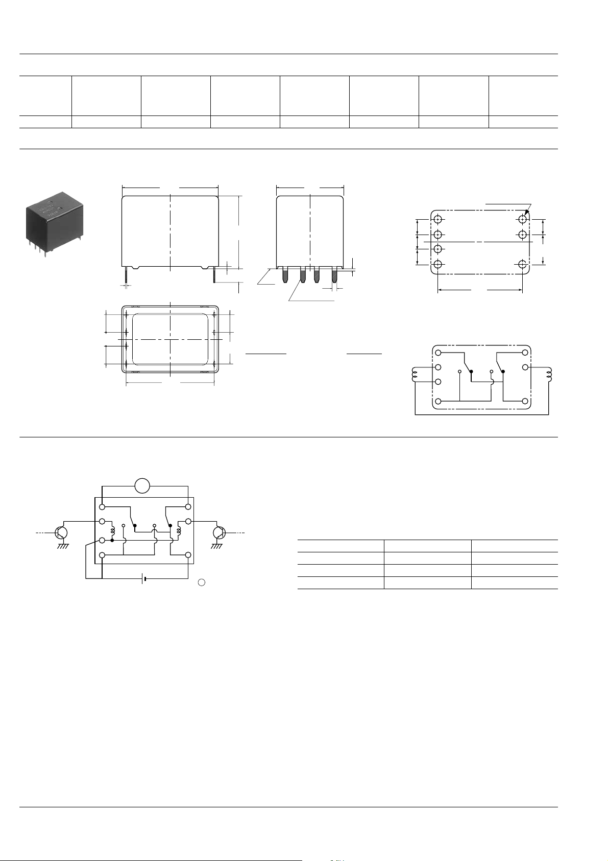
DIMENSIONS
24.6
.969
18.5
.728
0.6
.024
3.5
.138
A*
Dimension: Tolerance
4.5
.177
3.5
.138
7-0.25
.010
4.5
.177
8.0
.315
Max. 1mm .039 inch: ±0.1 ±.004
4.5
.177
* Dimensions (thickness and width) of terminal specified in this catalog is measured before pre-soldering.
Intervals between terminals is measured at A surface level.
22.4
.882
1 to 3mm .039 to .118 inch: ±0.2 ±.008
Min. 3mm .118 inch: ±0.3 ±.012
17.0
.669
Pre-soldering
EXAMPLE OF CIRCUIT
Forward/reverse control circuits of DC motor for power window
Max.
1.0
.039
7-1.2
.047
mm inch
PC board pattern (Bottom view)
+0.1
7-1.5 dia
0
+.004
7-.059 dia
0
4.5
.177
3.5
.138
4.5
.177
22.4
.882
Tolerance: ±0.1 ±.004
Schematic (Bottom view)
COM1 COM2
COIL
NCNO
8.0
.315
4.5
.177
M
COM COM
Tr1 Tr2
NO
12 VDC
NC
M
Power window motor
Tr1 Tr2 Motor
OFF OFF Stop
ON OFF Forward
OFF ON Reverse
All Rights Reserved © COPYRIGHT Matsushita Electric Works, Ltd.
Page 3

REFERENCE DATA
1-(1). Coil temperature rise (at room
temperature)
Sample: CR2-12V, 5pcs
Contact carrying current: 10A, 15A, 20A
Ambient temperature: Room temperature
200
1-(2). Coil temperature rise (at 85°C 185°F)
Sample: CR2-12V, 5pcs
Contact carrying current: 10A, 15A
Ambient temperature: 85°C 185°F
200
CR
2. Max. switching capability (Resistive load,
initial)
60
(N.O. side Room temperature)
160
120
80
Temperature rise, °C
40
0
12 14 16
Coil applied voltage, V
3. Ambient temperature and operating
temperature range
40
35
30
25
20
15
Coil applied voltage, VDC
10
5
0
–40 –20 20 40 60 1000 120
Pick-up voltage
(Cold start)
Ambient temperature, °C
8085
20A
15A
10A
160
120
80
Temperature rise, °C
40
0
12 14 16
15A
10A
Coil applied voltage, V
50
40
30
20
Switching voltage, VDC
10
0
020304010 50
Switching current, A
4. Ambient temperature characteristics 5. Distribution of pick-up and drop-out voltage
Sample: CR2-12V, 100pcs
80
Pick-up voltage upper limit
70
60
50
40
30
20
Ratio against the rated voltage, %V
10
Pick-up voltage lower limit
0
–40 –20 20 40 60 1000
Ambient temperature, °C
80
70
60
50
40
Frequency, n
30
20
10
0
1.5 2.0 2.5 3.0 3.5 4.5 5.04.0 5.5 6.0 6.5 7.0 7.5
Pick-up voltage
Drop-out voltage
Voltage, V
6. Distribution of operate time
Sample: CR2-12V, 100pcs
100
90
80
70
60
50
Quantity, n
40
30
20
10
0
3.02.01.5 2.5 3.5 4.5 5.04.0 5.5 6.0 6.5
Time, ms
8-(1). Operation noise distribution
When operated
50
40
30
Frequency
20
10
7. Distribution of release time
Sample: CR2-12V, 100pcs
* With diode
100
90
80
70
60
50
Quantity, n
40
30
20
10
0
3.02.01.5 2.5 3.5 4.5 5.04.0 5.5 6.0 6.5
Time, ms
8-(2). Operation noise distribution
When released
50
40
30
Frequency
20
10
Measuring conditions
Sample: CR2-12 V, 50 pcs.
Equipment setting: “A” weighted, Fast, Max. hold
Coil voltage: 12V DC
Coil connection device: Diode
Background noise: Approx. 20dB
Microphone
Relay
50mm
1.969inch
Sponge
0
40 42 44 46 48 50 52 5654
Noise level, dB
0
36 38 40 42 4644 48 50 52
Noise level, dB
All Rights Reserved © COPYRIGHT Matsushita Electric Works, Ltd.
Page 4

CR
Max.
Min.
X(N.C.)
0
No. of operations, × 10
4
Contact resistance, mΩ
Max.
Min.
X(N.O.)
50
40
30
20
10
010
N.O. side
N.C. side
9-(1). Electrical life test (Motor free)
Sample: CR2-12V, 3pcs
Load: Inrush current: 25A, Steady current: 6A,
Brake current: 15A,
power window motor actual load (free condition)
Tested voltage: 14V DC
Ambient temperature: Room temperature
Circuit
14VDC
Load current waveform
Inrush current: 25A, Steady current: 6A,
Brake current: 15A
Tested voltage: 14V DC
M
10A
100ms
Change of pick-up and drop-out voltage Change of contact resistance
10
9
8
7
6
5
4
3
Pick-up and drop-out voltage, V
2
1
0
02010
Pick-up voltage
Drop-out voltage
No. of operations, × 10
Max.
X
Min.
Max.
X
Min.
4
9-(2). Electrical life test (Motor lock)
Sample: CR2-12V, 3pcs
Brake current: 22A,
power window motor actual load (lock condition)
Tested voltage: 14V DC
Switching frequency: (ON:OFF = 0.5s:9.5s)
Ambient temperature: Room temperature
Circuit
14VDC
M
Load current waveform
Brake current: 22A
Tested voltage: 14V DC
5A
100ms
Motor
Change of pick-up and drop-out voltage Change of contact resistance
10
9
8
7
6
5
4
3
Pick-up and drop-out voltage, V
2
1
0
0105
Pick-up voltage
Drop-out voltage
No. of operations, × 10
Max.
X
Min.
Max.
X
Min.
4
50
40
30
20
Contact resistance, mΩ
10
0
0105
No. of operations, × 10
N.C. side
N.O. side
4
Max.
X
Max.
Min.
X
Min.
For Cautions for Use, see Relay Technical Information.
All Rights Reserved © COPYRIGHT Matsushita Electric Works, Ltd.
 Loading...