

Page 1
Technical Guide
CR5 Mechanism
Traverse Disassembly
Tray Removal and Assembly
Panasonic Services Company
National Training Center
Page 2

CR5 Mechanism
Produced by
Panasonic Services Company
National Training Department
Secaucus, NJ
Warning
This service information is designed for experienced repair technicians only and is not designed for use by
the general public. It does not contain warnings or cautions to advise non-technical individuals of potential
dangers in attempting to service a product. Products powered by electricity should be serviced or repaired
only by experienced professional technicians. Any attempt to service or repair the product or products
dealt with in this service information by anyone else could result in serious injury or death.
•
The numbers in parenthesis are the Reference Numbers for the parts named.
Page 3
CR5 Mechanism
Traverse Unit Disassembly
1. Traverse should be in down position. All trays should be on the tray
compartment side of the deck.
2. The deck should be placed upside down.
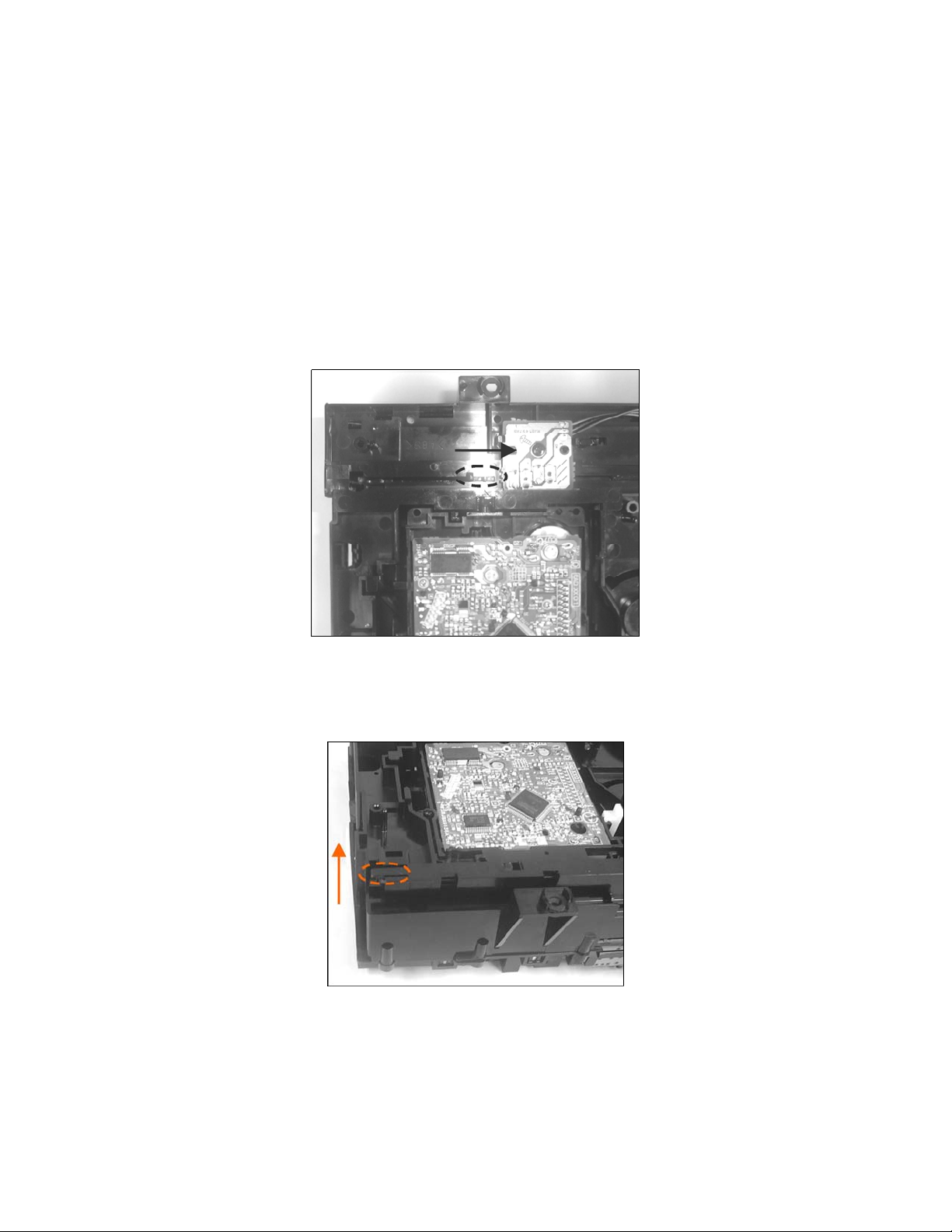
3. Apply backward and downward force on the front smaller post while pushing
and holding the larger back post of the Slide Plate Lever 1 (320) forward in
the direction of the arrow. See Figure 1.
Figure 1
4. Pull up on the rear tab to release the two slide plate levers. See Figure 2.
Figure 2
•
The numbers in parenthesis are the Reference Numbers for the parts named.
Page 4

CR5 Mechanism
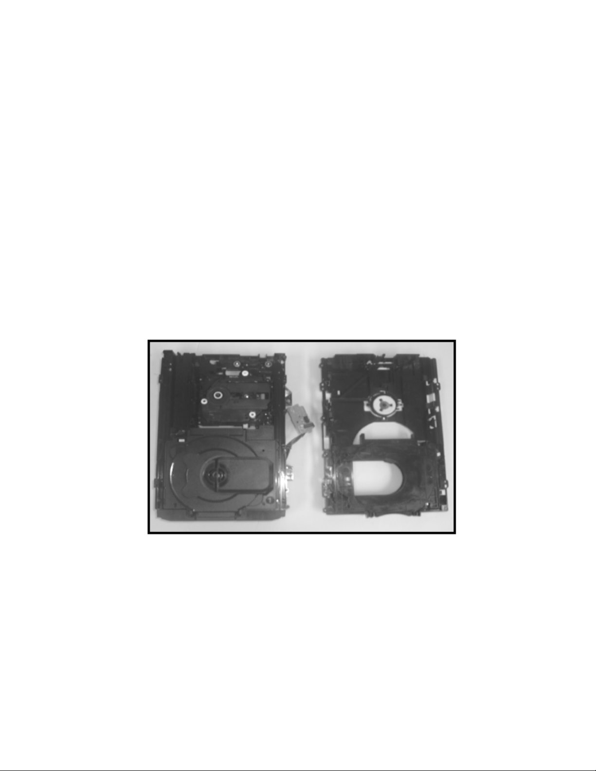
5. All three grooves of the traverse are now fully exposed. The traverse
assembly can now be pulled up and out of the deck. See figures 3 and 4.
Tray Removal
1. There are seven screws that attach the Mechanism Top Cover Assembly
(344) to the Mechanism Base Assembly (315). Two are on the right side,
Figure 5, and five are on the left side, Figure 6. Remove all seven screws.
•
The numbers in parenthesis are the Reference Numbers for the parts named.
Page 5

CR5 Mechanism
2. Remove the Tray Switch PCB from the Mechanism Top Cover Assembly
(344) by pulling back the two tabs holding it in place. Then pull the PCB up
and out of the holder. See Figure 7.
3. Remove the Mechanism Top Cover Assembly (344) from the Mechanism
Base assembly (315) by just pulling it off. Then lay it aside. The Top Cover
Assembly should contain four of the five CD Trays. The remaining CD Tray
should be laying on the Mechanism Base Assembly as shown in Figure 8.
4. Remove the CD Tray that remains on top of the Mechanism Base Assembly
(315). The CD Tray comes right out, with nothing holding it in. Now the Tray
Base Lock Lever (327) will be revealed.
•
The numbers in parenthesis are the Reference Numbers for the parts named.
Page 6

CR5 Mechanism
5. Release the Tray Base Lock Lever (327) by pulling the front part of it in the
direction of the arrow. See Figure 9. The Tray Base (329) will now be
released. Pull it forward until it cannot come out anymore. At this point it will
have reached the two stoppers.
6. One stopper is on the back left, shown in Figure 10, while the other is on the
right shown in Figure 11. Release the tabs in the direction of the arrows in
Figures 10 & 11. Then pull the Tray Base (329) forward until it is free from the
Mechanism Base Assembly (315).
•
The numbers in parenthesis are the Reference Numbers for the parts named.
Page 7

CR5 Mechanism
Tray Assembly
1. Position the Drive Rack (336) back as far as it can go on the bottom of the left
leg of the Tray Base (329). See Figure 12. The Carrier Lever (334) on the top
of the Tray Base, should be pulled all the way forward until it is held in place
by the Carrier Lock Lever (328). See figure 13.
2. While holding the Drive Rack (336) in place, insert the two Tray Base (329)
legs into the tracks of the Mechanism Base Assembly (315). Continue
pushing in until the first tooth of the Drive Rack meets the Drive Gear (303).
See Figure 14.
•
The numbers in parenthesis are the Reference Numbers for the parts named.
Page 8

CR5 Mechanism
3. While holding the Drive Rack to the Drive Gear with one hand, start turning
the Pulley Gear (302) in the clockwise direction. See Figure 14. The Tray
Base will begin to pull in. After a few turns you should be able to push the
Tray Base in the rest of the way.
4. Now with the Tray Base (329) back in the Mechanism Base Assembly (315),
place CD Tray #1 (307) on the Tray Base. Make sure the Hole (Groove) of
the CD Tray is fitted with the Tray Hook Spring (331). See Figure 15.
5. The other CD Trays numbered 2 through 5 (308 – 311) should be stacked
one on top of the other, with # 2 on the bottom and # 5 on top. Place these
Trays in the Mechanism Top Cover Assembly (344) with the Top Cover
Assembly facing right side up.
6. Place the Mechanism Top Cover Assembly (334) back on top of the
Mechanism Base Assembly (315). The Tray Switch PCB should be reinserted into its holder. Insert the seven screws and the re-assembly is
complete.
•
The numbers in parenthesis are the Reference Numbers for the parts named.
 Loading...