

Panasonic CR14 Diagram
CR14
ORDER NO. MD0801004CE
A6
Mechanism Unit
CONTENTS
Page Page
1 Mechanism Overview 2
2 Prevention of Electrostatic Discharge (ESD) to
Electrostatically Sensitive (ES) Devices
3 Precaution of Laser Diode
4 About Lead Free Solder (PbF)
5 Handling Precautions for Traverse Unit
6 Mechanism Drive Unit
7 Mechanism Operations Description
8 CR14 Mechanism Reliability
9 Before Disassembly 16
10 Disassembling and Assembling Procedure
3
11 Disassembly Flow
12 Notes of Schematic Diagram
4
5
13 Schematic Diagram
6
14 Printed Circuit Board
15 Exploded Views
8
11
16 Replacement Parts List
12
24
59
61
62
63
65
67
© 2008 Matsushita Electric Industrial Co. Ltd.. All
rights reserved. Unauthorized copying and
distribution is a violation of law.
CR14
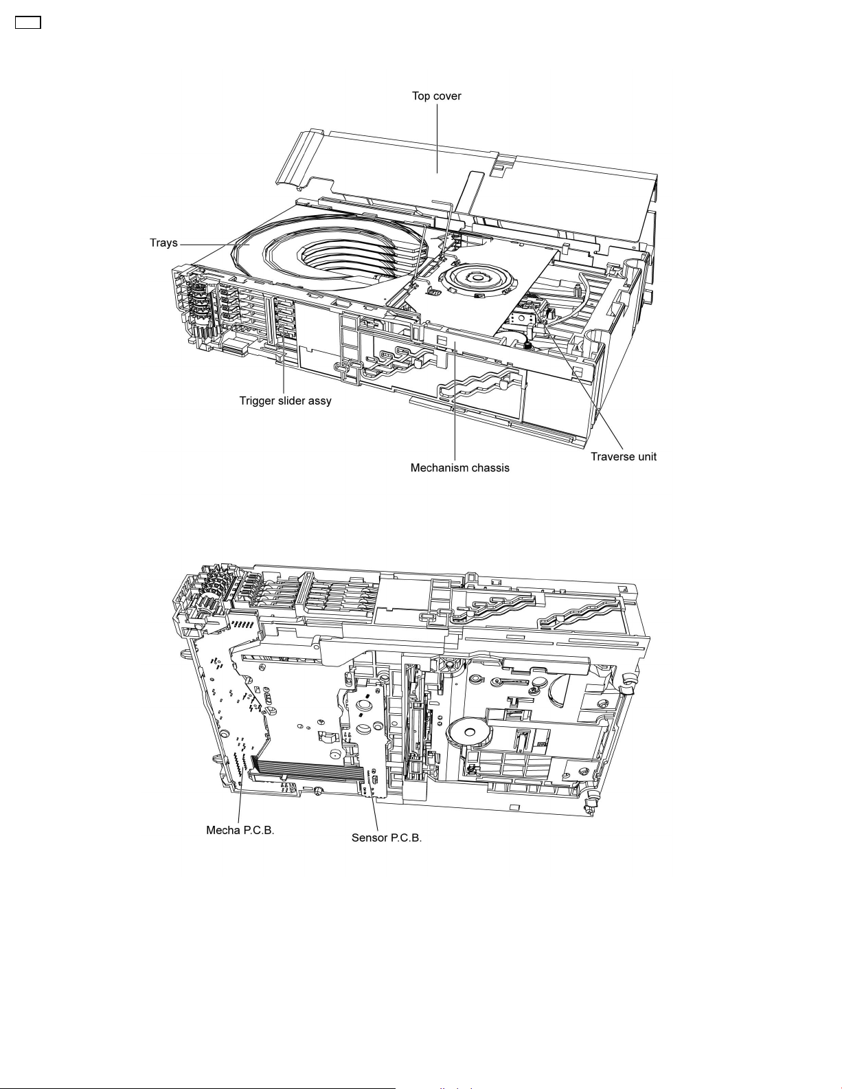
1 Mechanism Overview
2

2 Prevention of Electrostatic Discharge (ESD) to
Electrostatically Sensitive (ES) Devices
Some semiconductor (solid state) devices can be damaged easily by static electricity. Such components commonly are called
Electrostatically Sensitive (ES) Devices. Examples of typical ES devices are integrated circuits and some field-effect transistors and
semiconductor "chip" components. The following techniques should be used to help reduce the incidence of component damage
caused by electrostatic discharge (ESD).
1. Immediately before handling any semiconductor component or semiconductor-equipped assembly, drain off any ESD on your
body by touching a known earth ground. Alternatively, obtain and wear a commercially available discharging ESD wrist strap,
which should be removed for potential shock reasons prior to applying power to the unit under test.
2. After removing an electrical assembly equipped with ES devices, place the assembly on a conductive surface such as
aluminum foil, to prevent electrostatic charge buildup or exposure of the assembly.
3. Use only a grounded-tip soldering iron to solder or unsolder ES devices.
4. Use only an anti-static solder removal device. Some solder removal devices not classified as "anti-static (ESD protected)" can
generate electrical charge sufficient to damage ES devices.
5. Do not use freon-propelled chemicals. These can generate electrical charges sufficient to damage ES devices.
6. Do not remove a replacement ES device from its protective package until immediately before you are ready to install it. (Most
replacement ES devices are packaged with leads electrically shorted together by conductive foam, aluminum foil or comparable
conductive material).
7. Immediately before removing the protective material from the leads of a replacement ES device, touch the protective material
to the chassis or circuit assembly into which the device will be installed.
Caution:
Be sure no power is applied to the chassis or circuit, and observe all other safety precautions.
8. Minimize bodily motions when handling unpackaged replacement ES devices. (Otherwise harmless motion such as the
brushing together of your clothes fabric or the lifting of your foot from a carpeted floor can generate static electricity (ESD)
sufficient to damage an ES device).
CR14
3
CR14
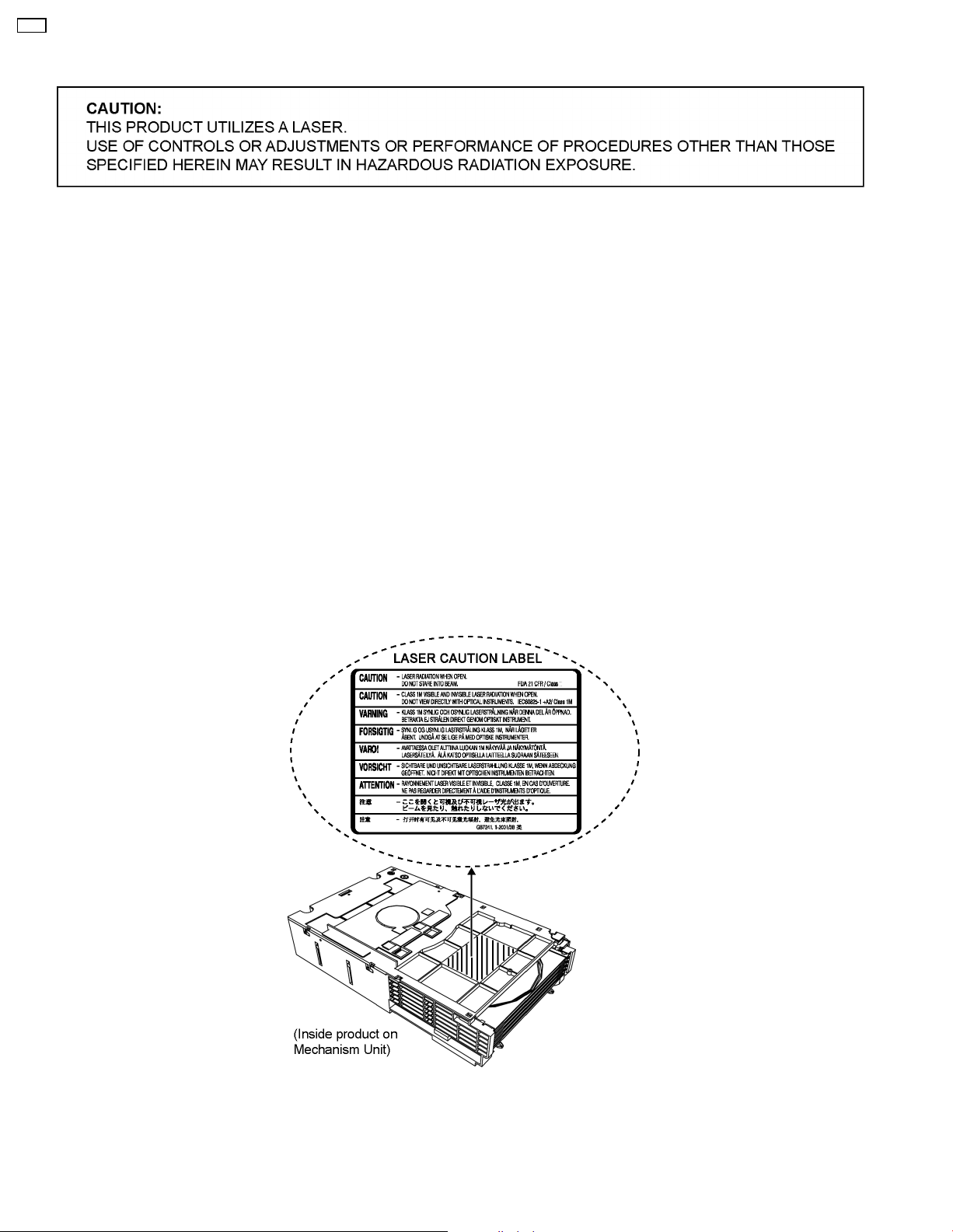
3 Precaution of Laser Diode
CAUTION :
This product utilizes a laser diode with the unit turned "on", invisible laser radiation is emitted from the pickup lens.
Wavelength: 655 nm (DVD)/785 nm (CD)
Maximum output radiation power from pickup: 100 µW/VDE
Laser radiation from the pickup unit is safety level, but be sure the followings:
1. Do not disassemble the pickup unit, since radiation from exposed laser diode is dangerous.
2. Do not adjust the variable resistor on the pickup unit. It was already adjusted.
3. Do not look at the focus lens using optical instruments.
4. Recommend not to look at pickup lens for a long time.
ACHTUNG :
Dieses Produkt enthält eine Laserdiode. Im eingeschalteten Zustand wird unsichtbare Laserstrahlung von der
Lasereinheitadgestrahit.
Wellenlänge: 655 nm (DVD)/785 nm (CD)
Maximale Strahlungsleistung der Lasereinhelt: 100 µW/VDE
Die strahlungan der Lasereinheit ist ungefährlich, wenn folgende Punkte beachtet werden:
1. Die Lasereinheit nicht zerlegen, da die Strahlung an der freigelegten Laserdiode gefährlich ist.
2. Den werksseitig justierten Einstellregler der Lasereinheit nicht verstellen.
3. Nicht mit optischen Instrumenten in die Fokussierlinse blicken.
4. Nicht über längere Zeit in die Fokussierlinse blicken.
4

4 About Lead Free Solder (PbF)
4.1. Service caution based on legal restrictions
4.1.1. General description about Lead Free Solder (PbF)
The lead free solder has been used in the mounting process of all electrical components on the printed circuit boards used for this
equipment in considering the globally environmental conservation.
The normal solder is the alloy of tin (Sn) and lead (Pb). On the other hand, the lead free solder is the alloy mainly consists of tin
(Sn), silver (Ag) and Copper (Cu), and the melting point of the lead free solder is higher approx.30 degrees C (86°F) more than that
of the normal solder.
Definition of PCB Lead Free Solder being used
The letter of “PbF” is printed either foil side or components side on the PCB using the lead free solder.
(See right figure)
Service caution for repair work using Lead Free Solder (PbF)
• The lead free solder has to be used when repairing the equipment for which the lead free solder is used.
(Definition: The letter of “PbF” is printed on the PCB using the lead free solder.)
• To put lead free solder, it should be well molten and mixed with the original lead free solder.
• Remove the remaining lead free solder on the PCB cleanly for soldering of the new IC.
• Since the melting point of the lead free solder is higher than that of the normal lead solder, it takes the longer time to melt
the lead free solder.
• Use the soldering iron (more than 70W) equipped with the temperature control after setting the temperature at 350±30
degrees C (662±86°F).
Recommended Lead Free Solder (Service Parts Route.)
• The following 3 types of lead free solder are available through the service parts route.
RFKZ03D01K-----------(0.3mm 100g Reel)
RFKZ06D01K-----------(0.6mm 100g Reel)
RFKZ10D01K-----------(1.0mm 100g Reel)
CR14
Note
* Ingredient: tin (Sn), 96.5%, silver (Ag) 3.0%, Copper (Cu) 0.5%, Cobalt (Co) / Germanium (Ge) 0.1 to 0.3%
5
CR14
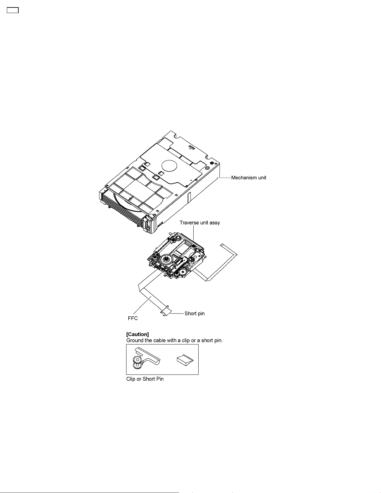
5 Handling Precautions for Traverse Unit
The laser diode in the optical pickup unit may break down due to static electricity of clothes or human body. Specia l care must be
taken avoid caution to electrostatic breakdown when servicing and handling the laser diode in the traverse unit.
5.1. Cautions to Be Taken in Handling the Optical Pickup Unit
The laser diode in the optical pickup unit may be damaged due to electrostatic discharge generating from clothes or human body.
Special care must be taken avoid caution to electrostatic discharge damage when servicing the laser diode.
1. Do not give a considerable shock to the optical pickup unit as it has an extremely high-precise structure.
2. To prevent the laser diode from the electrostatic discharge damage, the flexible cable of the optical pickup unit removed should
be short-circuited with a short pin or a clip.
3. The flexible cable may be cut off if an excessive force is applied to it. Use caution when handling the flexible cable.
4. The antistatic FPC is connected to the new optical pickup unit. After replacing the optical pickup unit and connecting the flexible
cable, cut off the antistatic FPC.
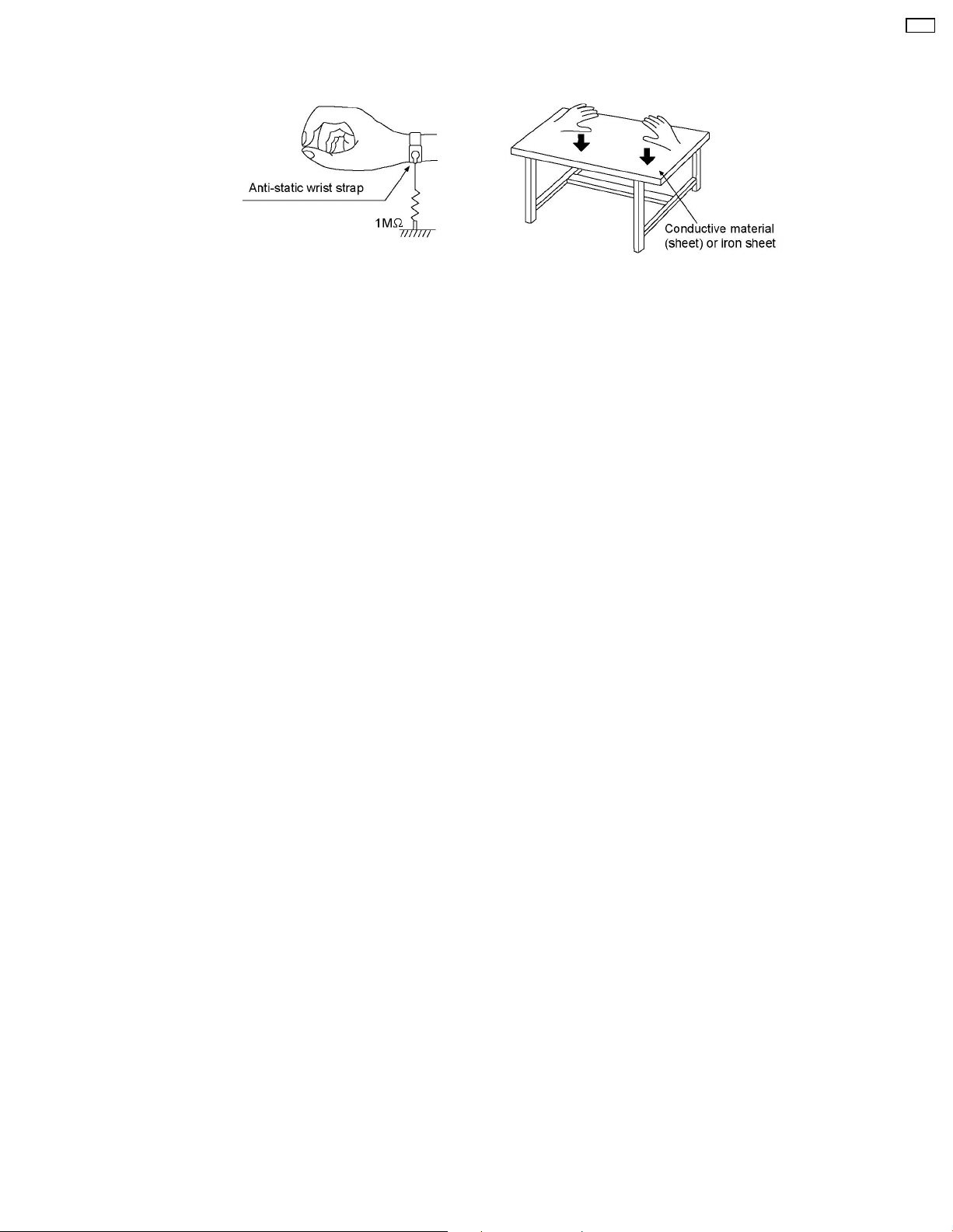
5.2. Grounding for electrostatic breakdown prevention
Some devices such as the DVD player use the optical pickup (laser diode) and the optical pickup will be damaged by static
electricity in the working environment. Proceed servicing works under the working environment where grounding works is
completed.
5.2.1. Worktable grounding
1. Put a conductive material (sheet) or iron sheet on the area where the optical pickup is placed, and ground the sheet.
5.2.2. Human body grounding
1. Use the anti-static wrist strap to discharge the static electricity form your body.
6
CR14
7
CR14
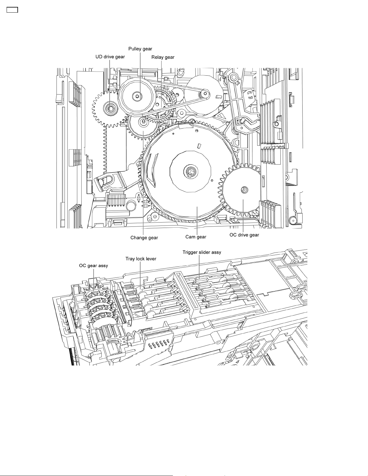
6 Mechanism Drive Unit
6.1. Description of trays open/close and discs exchange operations
1. The loading motor turns in the clockwise direction and the rotation is transmitted via the belt, the pulley gear also turns clockwise.
2. The relay gear turns counter clockwise.
3. The change gear turns clockwise.
4. The cam gear turns counter clockwise.
5. The OC drive gear turns clockwise driven OC gear assy.
6. Trigger slide assy releases tray lock lever.
7. Movement of OC gear assy releases all trays.
(The operation of trays closed is the opposi te of that for opening trays. Discs exchange is done during closing operation.)
8
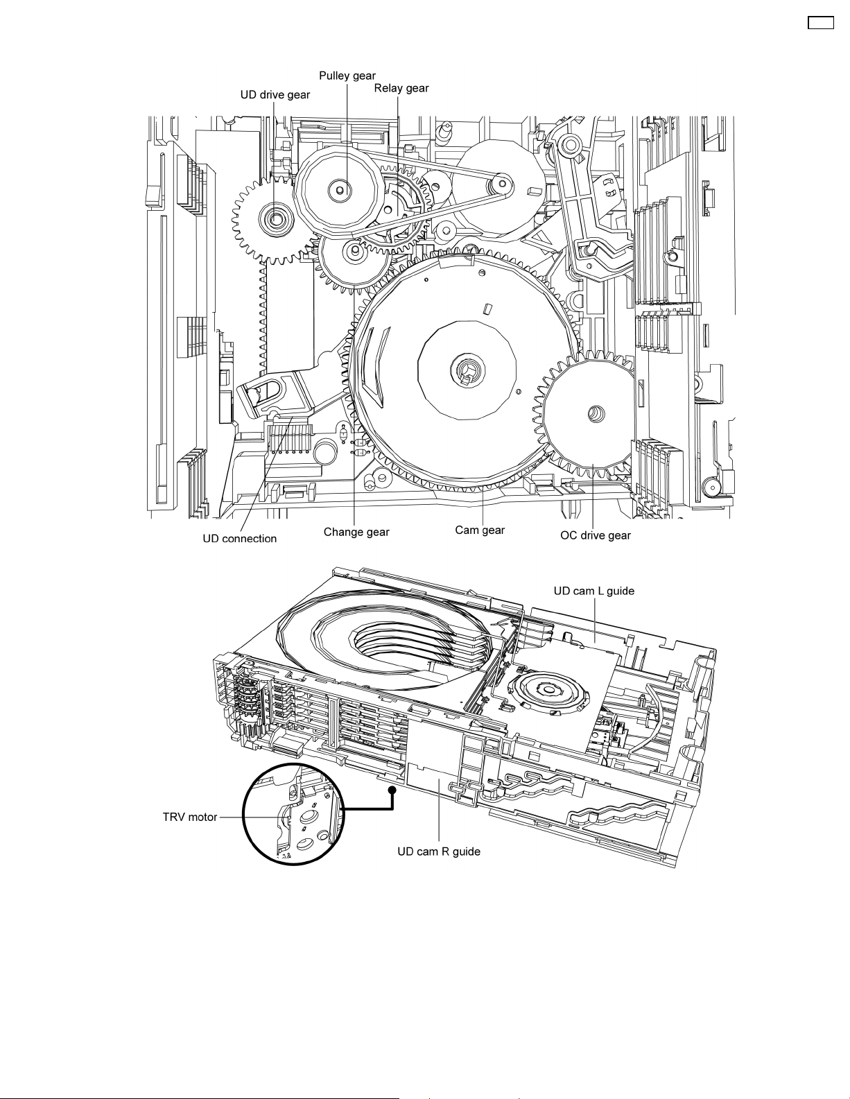
6.2. Description of tray selection operation
CR14
1. The loading motor turns in the clockwise direction and the rotation is transmitted via the belt, the pulley gear also turns clockwise.
2. The relay gear turns counter clockwise.
3. The change gear turns clockwise.
4. The cam gear turns counter clockwise.
5. The UD drive gear turns counter clockwise engages UD cam L guide drives UD connection turns counter clockwise, UD cam R
guide is driven to move UD base unit down.
(The operation of the UD base unit up is the opposite of that for the UD base unit down.)
9

CR14
6.3. Description of play operation
1. The loading motor turns in the clockwise direction and the rotation is transmitted via the belt, the pulley gear also turns cloc
2. The relay gear turns counter clockwise.
3. The change gear turns clockwise.
4. The cam gear turns counter clockwise.
5. Turn the TRV motor clockwise, the tray will load into play position until OPU at the centre position.
10

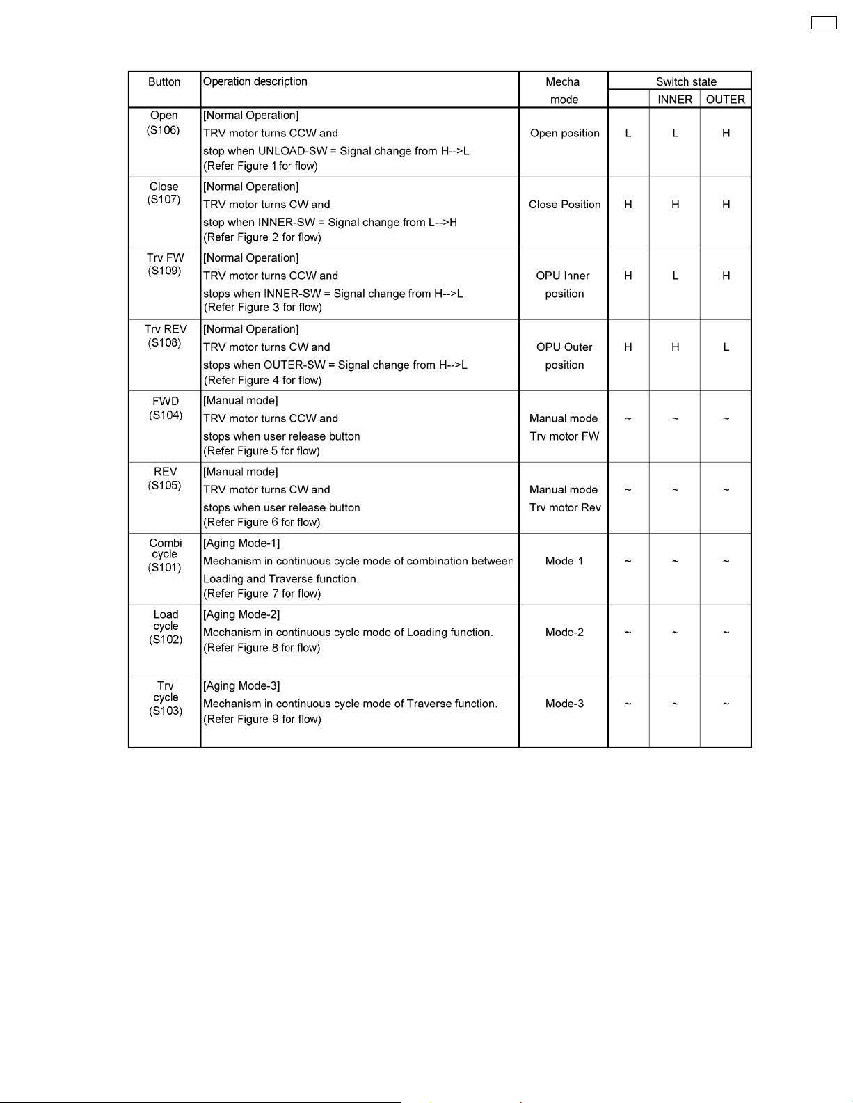
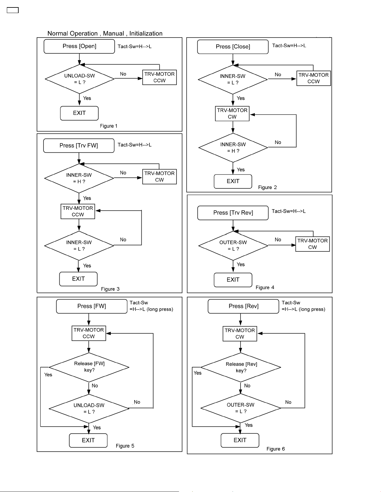
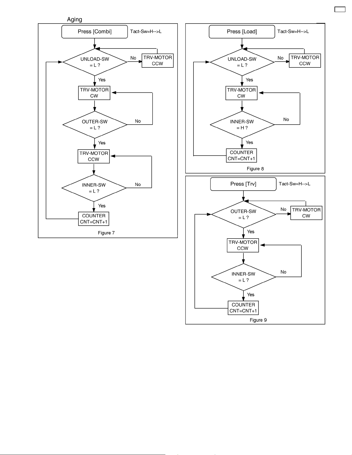
7 Mechanism Operations Description
This section is not available at the time of issue.
CR14
11
CR14
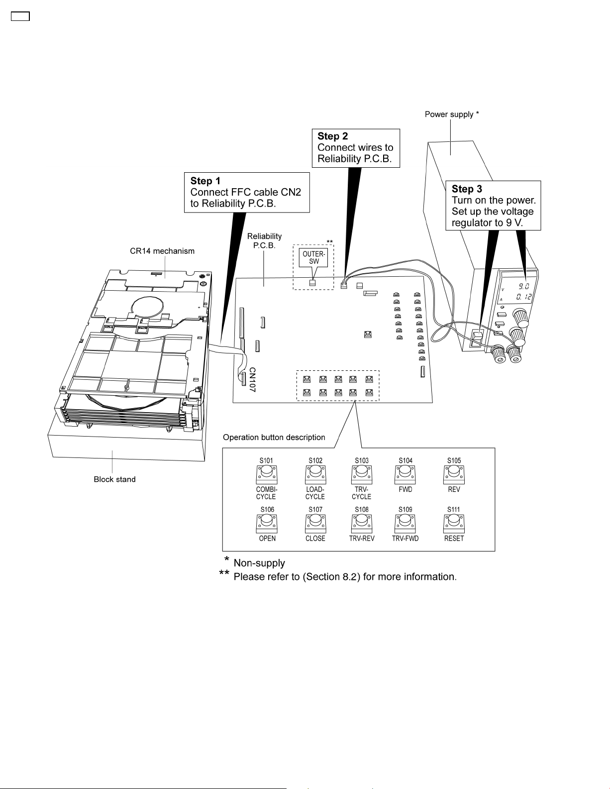
8 CR14 Mechanism Reliability
Purpose: To test the CR14 mechanism unit operation by using the Reliability P.C.B. before installation into the main unit.
8.1. Setup Connection
Below diagram shows the set-up necessary to carry out the reliability of mechanism.
Equipments required for the set up preparation:
- Power supply
- Reliability P.C.B. (RFKZCR14)
12
8.2. Jig’s Flow Diagram
CR14
13
CR14
8.2.1. Flow operation
14
CR14
15
CR14
9 Before Disassembly
9.1. Using Service Modes (Main
Unit)
9.1.1. In Service Mode 1
Purpose:
All trays in “STOCK” position, UD base unit at tray 5
position.
Refer to Section 10.2 for disassembling of Mechanism
unit.
Procedures:
• Press and hold “STOP” button followed by “FORWARD”
button to enter TEST mode.
• Press [1] button on main unit to enter Service Mode 1.
9.1.2. In Service Mode 2
Purpose:
In “PLAY” position, OPU at the centre position (see section
6.3 for more information).
Refer to Section 10.1 for disassembling of Traverse unit
assy.
9.2. Using Manually
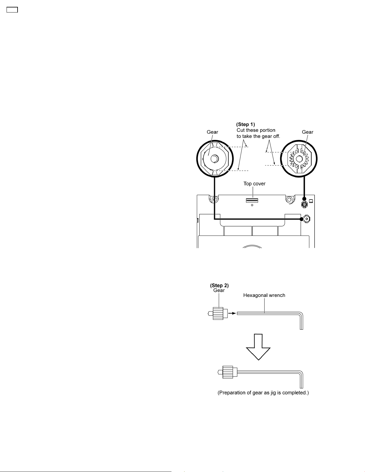
• Preparation of service jig
- This unit has two gears which are used for checking items
(open/close of tray, up/down operation of traverse unit by
manually) when servicing. (For gear information, that is
described on the items for disassembly procedures.)
- For preparation of gear (for servicing), perform the
procedures as follows.
- In case of re-servicing the same set, the “gear for
servicing” may be took off because it had been used. So,
the “gear for servicing” must be stored.
Procedures:
• Press and hold “STOP” button followed by “FORWARD”
button to enter TEST mode.
• Press [2] button on main unit to enter Service Mode 2.
Step 1: Cut the gear out from the top cover.
Note: The bigger gear is for loading hole and the smaller gear
is for traverse hole.
Step 2: Insert the gear into the hexago nal wrench.
16
9.2.1. Manually set to “UD” position
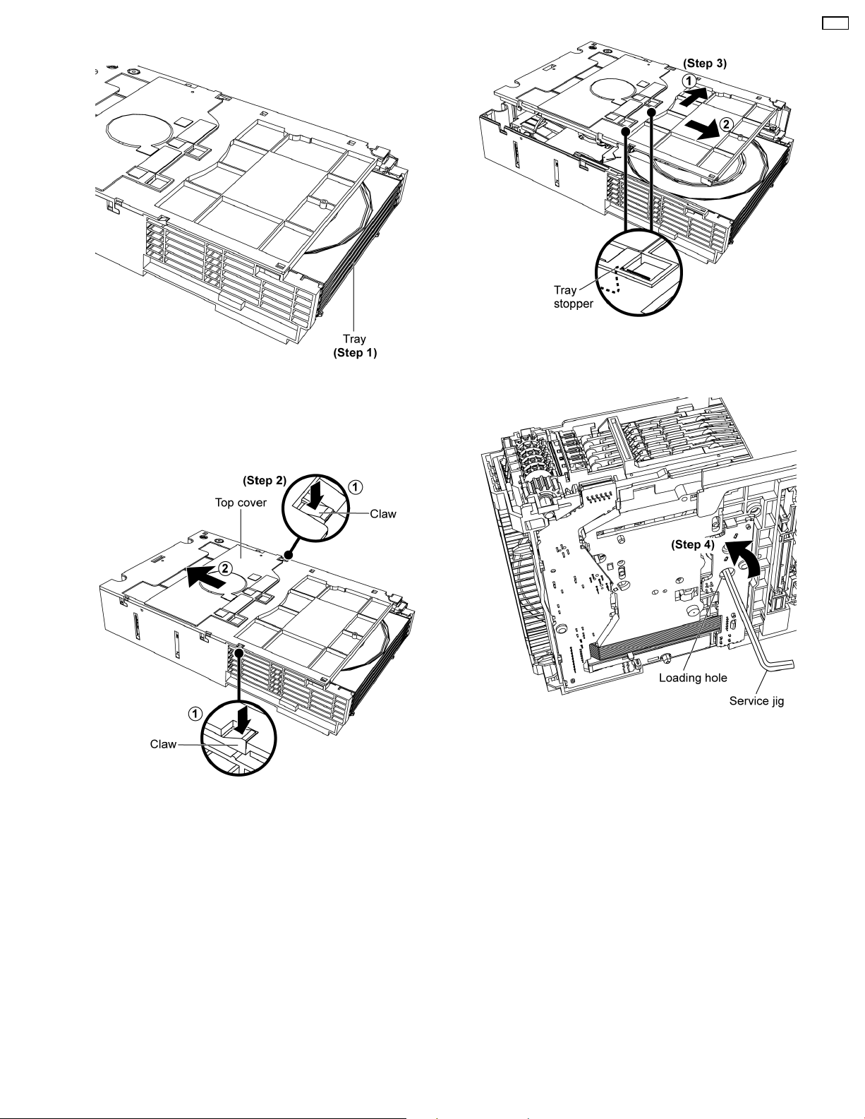
Step 1: Check any missing tray at the mechanism front.
Caution:
The missing tray is engaged in the play position.
CR14
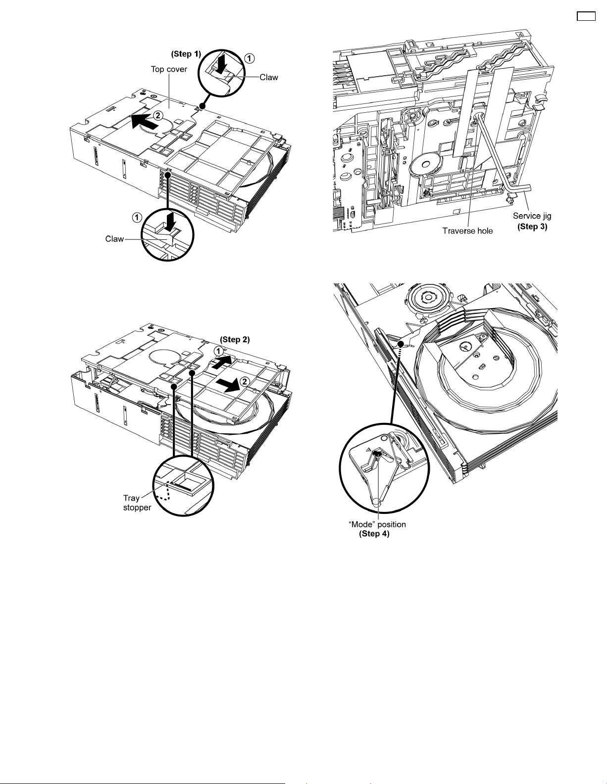
Step 3: Remove the top cover as arrows shown to release the
tray stoppers.
Step 2: Press both claws at the sides as arrows shown and
push the top cover backwards.
Step 4: Insert service jig into the loading hole, rotate the gear
counter clockwise.
17
CR14
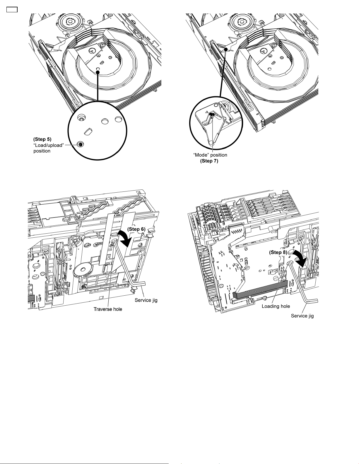
Step 5: Rotate the gear to “Load/upload” position.
Step 6: Insert service jig into the traverse hole, rotate the gear
clockwise.
Step 7: Rotate the gear to “Mode” position.
Step 8: Insert service jig into the loading hole, rotate the gear
clockwise.
18
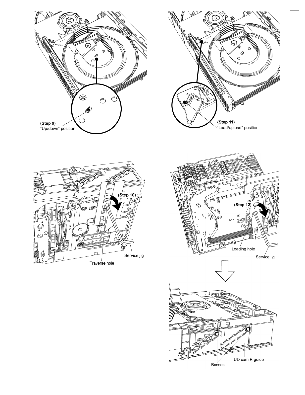
Step 9: Rotate the gear to “Up/down” position.
CR14
Step 11: Rotate the gear to “Load/upload” position.
Step 10: Insert service jig into the traverse hole, rotate the gear
clockwise.
Step 12: Insert service jig into the loading hole, rotate the gear
19
CR14
clockwise until both bosses positioned at the top of the UD cam
R guide.
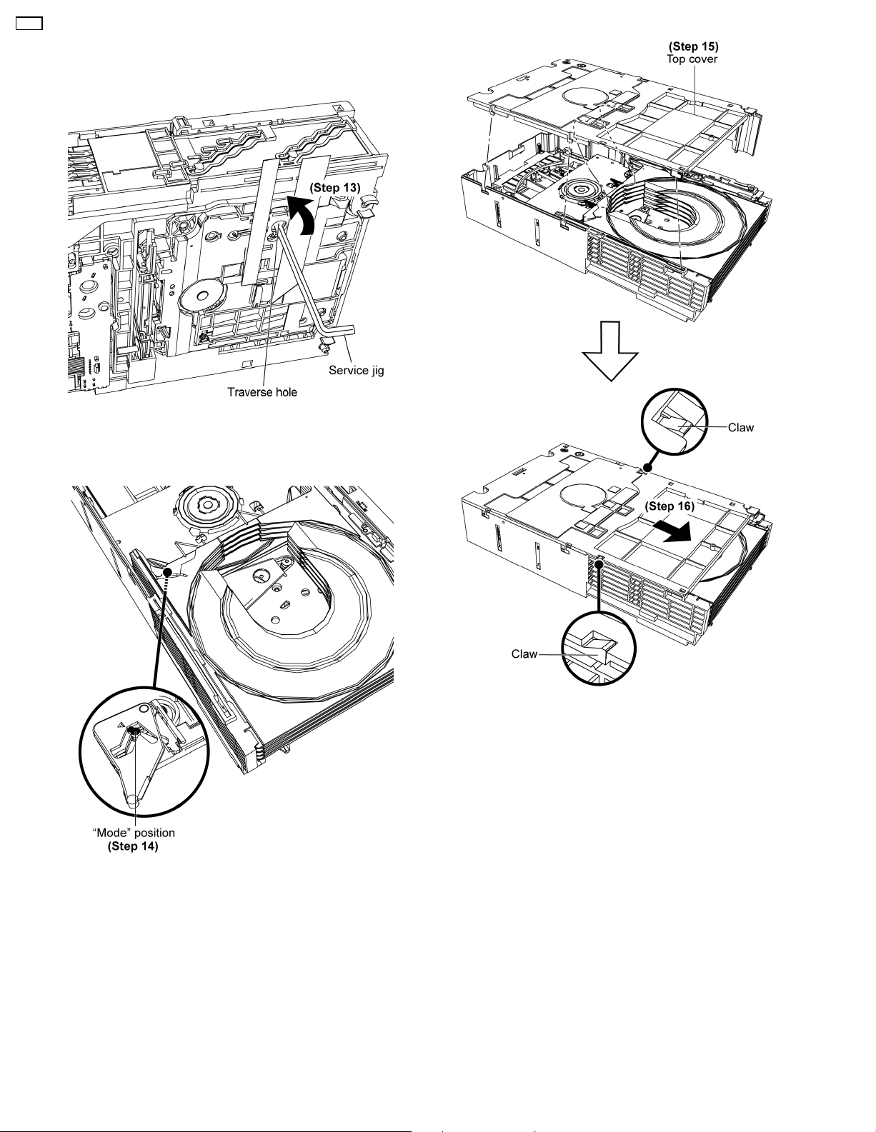
Step 13: Insert service jig into the traverse hole, rotate the gear
counter clockwise.
Step 14: Rotate the gear to “Mode” position.
Step 15: Attach the top cover to the tray stoppers.
Step 16: Slide the top cover as arrow shown.
Note: Ensure both claws are catched.
(Refer to Section 10.2 for disassembling of Mechanism
unit.)
20
9.2.2. Manually set to “PLAY” position
Step 1: Press both claws at the sides as arrows shown and
push the top cover backwards.
CR14
Step 3: Insert service jig into the traverse hole.
Step 2: Remove the top cover as arrows shown to release the
tray stoppers.
Step 4: Rotate the gear to “Mode” position.
21
 Loading...