

Page 1
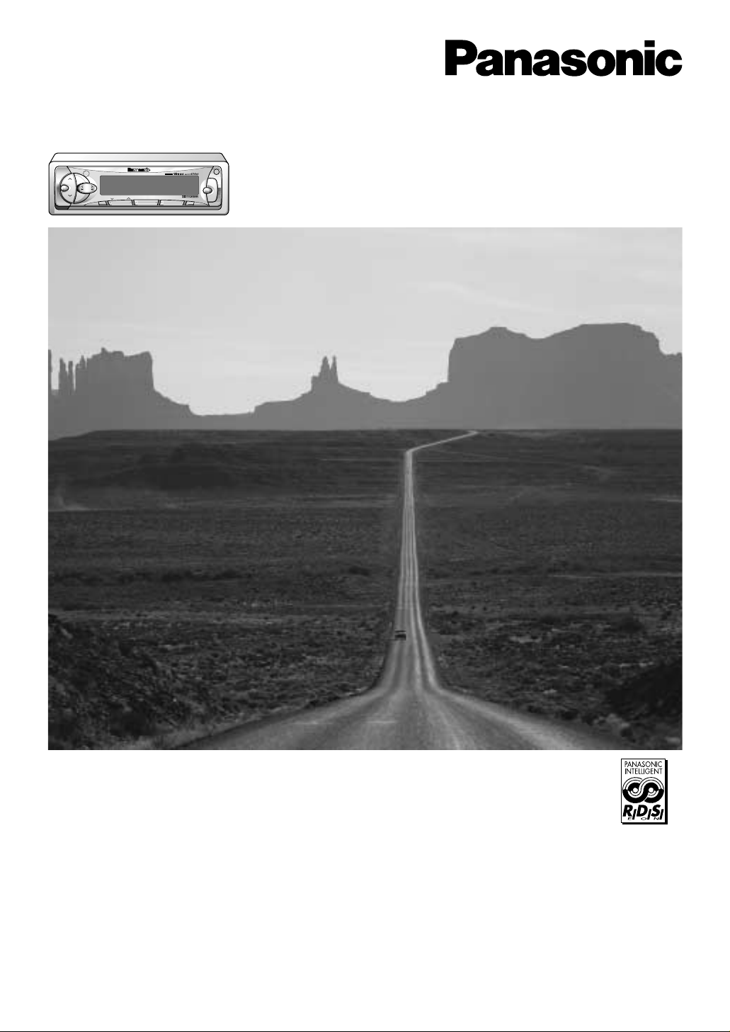
Cassette Player/Receiver with Changer Control
CQ-FX421/FX321N
Operating Instructions
¡Please read these instructions carefully before using this product and save this manual for future use.
¡Bitte lesen Sie diese Bedienungsanleitung vor der Verwendung dieses Produktes aufmerksam durch und bewahren Sie sie danach
für spätere Nachschlagzwecke sorgfältig auf.
¡Prière de lire ces instructions attentivement avant d’utiliser le produit et garder ce manuel pour l’utilisation ultérieure.
¡Leest u deze instructie alstublieft zorgvuldig door voor u dit product in gebruik neemt en bewaar deze handleiding voor later gebruik.
¡Läs igenom denna bruksanvisning noga innan produkten tas i bruk. Spara bruksanvisningen för framtida behov.
¡Si prega di leggere attentamente queste istruzioni prima di usare questo prodotto e di conservare questo manuale per usi futuri.
¡Lea con atención estas instrucciones antes de utilizar el producto y guarde este manual para poderlo consultar en el futuro.
Bedienungsanleitung
Manuel d’instructions
Gebruiksaanwijzing
Bruksanvisning
Manuale di istruzioni
Manual de Instrucciones
Bedienungsanleitung
Manuel d’instructions
Gebruiksaanwijzing
Bruksanvisning
Manuale di istruzioni
Manual de Instrucciones
VOL
SEL
SUB·W
OPEN
SOURCE
TA
PWR
AF
REG
TUNE
TRACK
BAND
SHB
DISC
PR
G
AUTO
·P
CQ-FX421N
EONEPTYECT
CASSETTE PLAYER/RECEIVER WITH CHANGER CONTROL
C
T
REPEAT
SCAN
RANDOM
MONO/LOC
DISP
PTY
1234
MTL NR TPS B·S REP
56
Page 2
2
CQ-FX421/FX321N
Contents
Page
Precautions (ISO Connector)....................... 4
Precautions ................................................... 6
Remote Control Unit Preparation................ 7
Power and Sound Controls.......................... 8
Radio Basics ................................................. 10
RDS (Radio Data System) ............................ 12
Inhaltsverzeichnis
Seite
Vorsichtsmaßnahmen (ISO-Stecker)........... 4
Vorsichtsmaßnahmen .................................. 28
Vorbereitung der Fernbedienung .............. 29
Stromversorgung und Klangregler ............. 30
Rundfunkempfang ........................................ 32
Radio-Daten-System (RDS)-Empfang ......... 34
Table des matières
Page
Mesures de précaution (connecteur ISO)
...... 4
Mesures de précaution................................. 50
Préparatifs pour la télécommande............ 51
Interrupteur d'alimentation et commandes
de réglage de la sonorité .......................... 52
Utilisation de base du récepteur radio ....... 54
Inhoudsopgave
Bladzijde
Voorzorgsmaatregelen (ISO aansluiting).... 4
Voorzorgen .................................................... 72
Voorbereiding afstandsbediening............. 73
Stroomvoorziening en geluidsregeling ...... 74
Basisbediening radio ................................... 76
RDS (Radio Data Systeem) .......................... 78
Innehåll
Sida
Observera (ISO-kontakt) .............................. 4
Observera ...................................................... 94
Förberedelser för fjärrstyrning.................. 95
Ström- och ljudreglage................................. 96
Grundläggande manövrering av radion ..... 98
RDS-mottagning (datastyrd radiomottagning)
100
Contenuto
Pag.
Precauzioni (Connettore ISO)...................... 4
Precauzioni.................................................. 116
Preparazione del telecomando ................ 117
Comandi di alimentazione e del suono..... 118
Funzionamento della radio ........................ 120
Ricezione RDS (Radio Data System) ........ 122
Indice
Pag.
Precauciones (conector ISO)..................... 4
Precauciones .............................................. 138
Preparativos del controlador remoto...... 139
Alimentación y controles del sonido ........ 140
Operación básica de la radio..................... 142
Recepción RDS
(sistema de datos radiofónicos) ........... 144
Page 3

3
CQ-FX421/FX321N
Clock Set ....................................................... 15
Cassette Tape Player Basics ....................... 16
CD Changer Basics ...................................... 18
Installation..................................................... 20
Anti-Theft System ......................................... 23
Electrical Connections ................................. 24
Speaker Connections ................................... 26
Fuse ............................................................... 26
Maintenance .................................................. 26
Specifications ............................................... 27
Uhrzeit (CT) ................................................... 37
Cassettenwiedergabe................................... 38
Grundlagen für die Bedienung des
CD-Wechslers .......................................... 40
Einbau............................................................ 42
Diebstahlschutz ............................................ 45
Elektrischer Anschluß .................................. 46
Anschluß der Lautsprecher ......................... 48
Sicherung ...................................................... 48
Pflege ............................................................. 48
Technische Daten ......................................... 49
Réception radio RDS (Radio Data System)
.... 56
Réglage de l'horloge
...................................... 59
Utilisation du lecteur de cassette................ 60
Utilisation de base du changeur de CD ...... 62
Installation..................................................... 64
Système antivol ............................................ 67
Branchements électriques........................... 68
Branchement des haut-parleurs.................. 70
Fusible ........................................................... 70
Entretien ........................................................ 70
Données techniques..................................... 71
Gelijk zetten van de klok .............................. 81
Basisbediening van de cassettespeler....... 82
Basisbediening van de CD-wisselaar ......... 84
Installatie ....................................................... 86
Anti-diefstal systeem.................................... 89
Elektrische aansluitingen ............................ 90
Aansluitingen luidsprekers.......................... 92
Zekering......................................................... 92
Onderhoud .................................................... 92
Technische gegevens................................... 93
Tidsinställning ............................................ 103
Grundläggande manövrering av
bandspelaren .............................................. 104
CD-växlarens grundläggande funktioner .106
Montering .................................................... 108
Stöldskyddsanordning ............................... 111
Elektriska anslutningar .............................. 112
Anslutning av högtalare ............................. 114
Säkring......................................................... 114
Underhåll...................................................... 114
Tekniska data............................................... 115
Regolazione dell'orologio .......................... 125
Funzionamento fondamentale del
riproduttore a cassette............................... 126
Funzionamento fondamentale del
Cambia CD................................................... 128
Installazione ................................................ 130
Sistema antifurto ........................................ 133
Collegamenti elettrici ................................. 134
Collegamenti degli altoparlanti ................. 136
Fusibile ........................................................ 136
Manutenzione.............................................. 136
Dati tecnici................................................... 137
Ajuste de la hora......................................... 147
Operación básica del reproductor de casetes
.148
Conocimientos básicos del cambiador
de discos de CD
........................................ 150
Instalación .................................................. 152
Sistema antirrobo ....................................... 155
Conexiones eléctricas................................ 156
Conexiones de los altavoces..................... 158
Fusible ......................................................... 158
Mantenimiento ............................................ 158
Especificaciones......................................... 159
Page 4

4
CQ-FX421/FX321N
Precautions (ISO Connector)
Vorsichtsmaßnahmen (ISO-Stecker)
Mesures de précaution (connecteur ISO)
Voorzorgsmaatregelen (ISO aansluiting)
Observera (ISO-kontakt)
Precauzioni (Connettore ISO)
Precauciones (conector ISO)
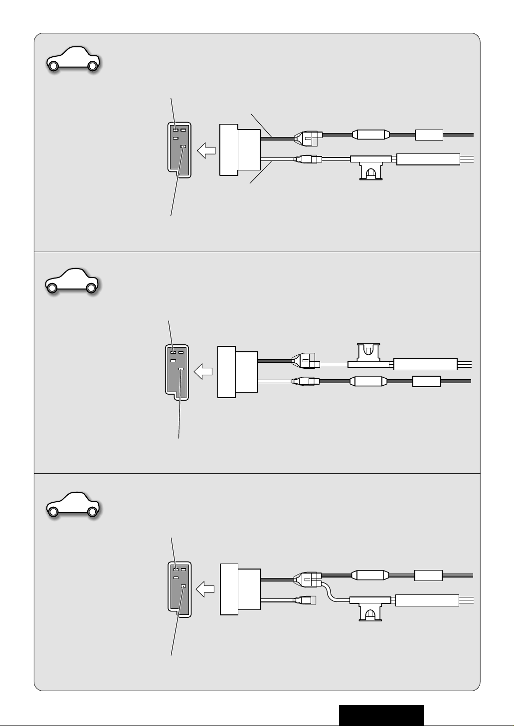
¡La disposición de las patillas del conector de alimentación
satisface las normas ISO.
¡La disposición de las patillas de los conectores ISO de
algunos vehículos puede ser distinta de las normas ISO.
¡Compruebe que la disposición de las patillas del conector de
su vehículo satisfaga las normas ISO.
¡Para los tipos A y B de vehículos, cambie las conexiones de
los cables rojo y amarillo como se muestra a la derecha.
¡Después de la conexión, aísle las partes marcadas con (C)
usando cinta aislante.
Nota: Para los vehículos que no sean de los tipos A y B, con-
sulte a su taller mecánico local.
¡La disposizione dei pin del connettore di alimentazione è
conforme allo standard ISO.
¡La disposizione dei pin dei connettori ISO in alcune automo-
bili potrebbe differire dallo standard ISO.
¡Accertarsi che la disposizione dei pin del connettore dell'au-
tomobile sia conforme allo standard INSTALLATO.
¡Per le macchine del tipo A e B, cambiare i collegamenti dei
cavi rosso e giallo come mostrato a destra.
¡Dopo il collegamento, isolare le parti contrassegnate colle-
gare (C) usando del nastro isolante.
Nota: Per le macchine diverse dal tipo A e B, rivolgersi a una
autorivendita locale.
¡Stiftens placering i strömkontakten överensstämmer med
ISO-standard.
¡I vissa bilar kan stiftens placering i ISO-kontakter skilja sig
från ISO-standard.
¡Kontrollera att stiftens placering i kontakten på din bil
överensstämmer med ISO-standard.
¡För biltyp A och B: ändra ledningsdragningen av de röda och
gula kablarna så som visas till höger.
¡Delar märkta med (C) måste efter slutförda anslutningar
isoleras med isoleringstejp.
Obs: Kontakta din lokala bilhandlare i fråga om bilar av annan
typ än A och B.
¡De pennen van de stroomaansluiting voldoen aan de vereis-
ten van de ISO standaard.
¡De pennen van ISO aansluitingen in sommige auto's kunnen
verschillen van de ISO standaard.
¡PControleer of de pennen van de aansluiting in uw auto vol-
doen aan de ISO standaard.
¡Voor auto's van de types A en B dienen de rode en gele
draden gewijzigd te worden zoals rechts staat aangegeven.
¡Na het aansluiten moeten de plekken die zijn aangegeven
met (C) afgeplakt worden met isolatieband.
Opmerking: voor auto's van andere types dan A en B dient u
uw plaatselijke garage te raadplegen.
¡La disposition des broches du connecteur d'alimentation est
conforme aux normes ISO.
¡La disposition des broches des connecteurs ISO de certaines
voitures risque d'être différente par rapport aux normes ISO.
¡Vérifier si la disposition des broches du connecteur de votre
voiture est conforme aux normes ISO.
¡En ce qui concerne les véhicules des types A et B, modifier
le câblage des fils rouge et jaune comme indiqué ci-contre.
¡Une fois le branchement réalisé, isoler les sections identi-
fiées par le signe (C) avec de l'adhésif isolant.
Remarque: En ce qui concerne les véicules des types A et B,
veuillez vous renseigner auprès de votre concessionnaire
automobile habituel.
¡Die Stiftanordnung des Versorgungssteckers entspricht dem
ISO-Standard.
¡Die Stiftanordnung der ISO-Stecker im manchen Fahrzeugen
kann von dem ISO-Standard abweichen.
¡Bitte stellen Sie sicher, daß die Stiftanordnung des Steckers
in Ihrem Fahrzeug dem ISO-Standard entspricht.
¡Für Fahrzeugtypen A und B die Verdrahtung der roten und
gelben Kabel gemäß rechter Abbildung äudern.
¡Nach der Verkabelung sollte unbedingt der durch (C)
gekennzeichnete Teil mit Hilfe von Isolierbändern o.ä. isoliert
werden.
Hinweis: Für andere als die Fahrzeugtypen A und B wenden
Sie sich bitte an Ihre örtliche Werkstatt.
¡The pin arrangement of the power connector conforms to
ISO standard.
¡The pin arrangement of ISO connectors in some cars may
differ from the ISO standard.
¡Please check that the pin arrangement of the connector in
your car conforms to ISO standard.
¡For car types A and B, change the wiring of the red and yel-
low leads as shown at right.
¡After connection, insulate the portions marked (C) with
insulating tape.
Note: For cars other than types A and B, please consult your
local car shop.
Page 5
5
CQ-FX421/FX321N
Standard ISO
¡IGN or ACC
switched 12V supply
¡Zündschalter
(ACC/IGN)
¡Sélecteur ACC/IGN
¡ACC/IGN schakelaar
¡tändningsomkopplare
¡Interruttore ACC/IGN
¡Llave ACC/IGN
¡+12 V Battery
(Permanent supply)
¡+12 V-Batterie
¡Batterie +12 V
¡+12 V accu
¡+12 V batteri
¡Batteria +12 V
¡+12 V Batería
Car Type A
¡+12 V Battery
(Permanent supply)
¡+12 V-Batterie
¡Batterie +12 V
¡+12 V accu
¡+12 V batteri
¡Batteria +12 V
¡+12 V Batería
¡IGN or ACC
switched 12V supply
¡Zündschalter
(ACC/IGN)
¡Sélecteur ACC/IGN
¡ACC/IGN schakelaar
¡tändningsomkopplare
¡Interruttore ACC/IGN
¡Llave ACC/IGN
Car Type B
¡+12 V Battery
(Permanent supply)
¡+12 V-Batterie
¡Batterie +12 V
¡+12 V accu
¡+12 V batteri
¡Batteria +12 V
¡+12 V Batería
¡No connection
¡Kein Anschluß
¡Non connecté
¡Niet aangesloten
¡ingen anslutning
¡Non collegato
¡Sin conexión
B
A
ISO
A7
A4
C
C
(Red)
(Rot)
(Rouge)
(Rood)
(Röd)
(Rosso)
(Rojo)
(Red)
(Rot)
(Rouge)
(Rood)
(Röd)
(Rosso)
(Rojo)
(Yellow)
(Gelb)
(Jaune)
(Geel)
(Gul)
(Giallo)
(Amarillo)
(Yellow)
(Gelb)
(Jaune)
(Geel)
(Gul)
(Giallo)
(Amarillo)
A7
A4
BATTERY 15A
ACC
C
C
(Red)
(Rot)
(Rouge)
(Rood)
(Röd)
(Rosso)
(Rojo)
(Red)
(Rot)
(Rouge)
(Rood)
(Röd)
(Rosso)
(Rojo)
(Yellow)
(Gelb)
(Jaune)
(Geel)
(Gul)
(Giallo)
(Amarillo)
(Yellow)
(Gelb)
(Jaune)
(Geel)
(Gul)
(Giallo)
(Amarillo)
BATTERY 15A
ACC
A7
A4
(Red)
(Rot)
(Rouge)
(Rood)
(Röd)
(Rosso)
(Rojo)
(Red)
(Rot)
(Rouge)
(Rood)
(Röd)
(Rosso)
(Rojo)
(Yellow)
(Gelb)
(Jaune)
(Geel)
(Gul)
(Giallo)
(Amarillo)
(Yellow)
(Gelb)
(Jaune)
(Geel)
(Gul)
(Giallo)
(Amarillo)
BATTERY 15A
ACC
C
C
A7
A4
Page 6
6
CQ-FX421/FX321N
1
E
N
G
L
I
S
H
Panasonic welcomes you to their constantly growing family of electronic products owners.
We endeavor to give you the advantages of precise electronic and mechanical engineering, manufactured with carefully selected components, and assembled by people who are proud of the reputation their
work has built for our company. We know this product will bring you many hours of enjoyment, and after
you discover the quality, value and reliability we have built into it, you too will be proud to be a member of
our family.
Precautions
Volume Level
For your driving safety, keep the volume level low enough to be aware of road
and traffic conditions.
Car Washing
To avoid electrical shorts which may cause fire, or other damage, do not
expose this Product (including the speakers and tape) to water or excessive
moisture.
Car Ventilation
If your car is parked for several hours in direct sunlight, the temperature inside the car may become very high. It is advisable to
drive the car and give the interior a chance to cool down before switching the
unit on.
Power Supply
This Product is designed to be used in a car having a 12-Volt negative ground
battery system.
Tape Mechanism
Keep magnets, screwdrivers and other metallic objects away from the tape
mechanism and tape head.
Service
This Product is made of precision parts. Do not attempt to disassemble or
adjust any parts. For repair, please consult your nearest authorized
Panasonic Service Center.
Note: The preset memory is cleared to return to the original factory setting
when the power connector or battery is disconnected.
Model
Features
Note: This operating instruction manual is for two models CQ-FX421N and CQ-FX321N.
The differences between these models are mentioned below. All illustrations throughout this manual represent model CQ-FX421N unless otherwise specified.
CQ-FX421N CQ-FX321N
Sub-Woofer Out (Level) Yes (2V) None
LCD Color Multi Color Blue
S•HDB Yes None
Loudness None Yes
Remote Control Supplied Option
Pre-out 2 (Front/Rear) 1 (Rear)
CD Changer Input Cord type Fix type
Page 7
7
CQ-FX421/FX321N
2
E
N
G
L
I
S
H
Remote Control Unit Preparation
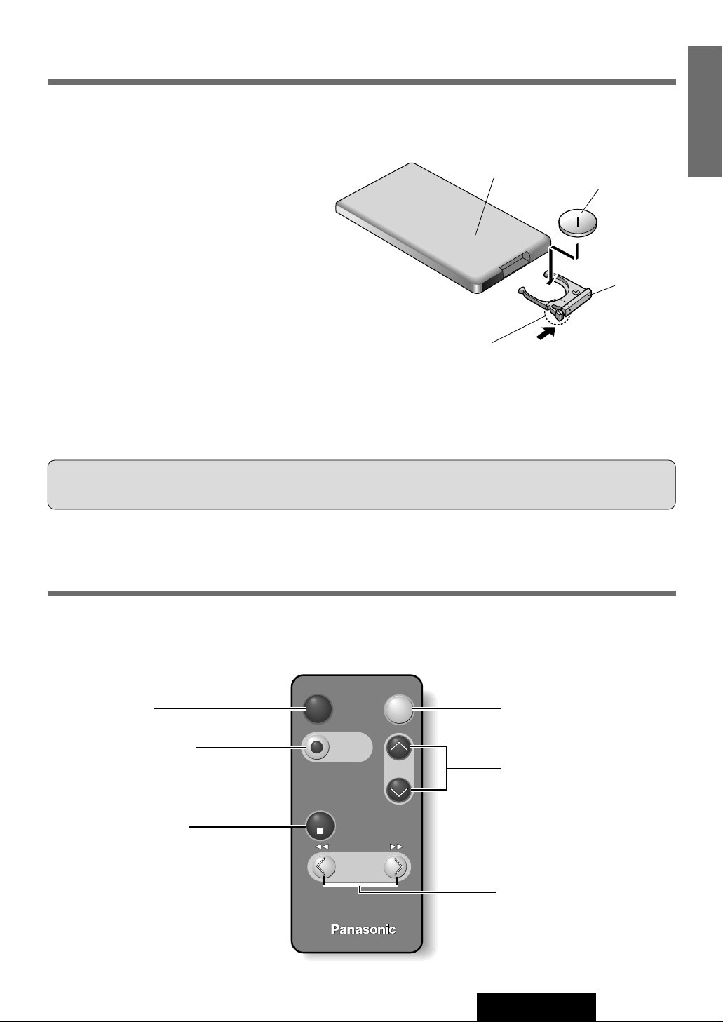
Battery Installation
q Remove the battery holder.
Take hold of the holder at position B and pull it out
by pushing position A in the direction shown by the
arrow.
w Install the battery on the battery holder.
Set a new battery properly with its (+) side facing
up as shown in the figure.
e Insert the battery holder.
Push in the battery holder back into its original
position.
Battery Notes
Remove and dispose of an old battery immediately.
Battery Information:
¡Battery Type:Panasonic lithium battery (CR2025)
¡Battery Life: Approximately 6 months under normal
use (at room temperature)
(Back side)
Lithium battery
Position B
Position A
Battery holder
Caution: Improper use of batteries may cause overheating, an explosion or ignition, resulting in injury or a fire. Battery
leakage may damage the unit.
¡Do not disassemble or short the battery. Do not throw a battery into a fire.
¡Keep batteries away from children to avoid the risk of accidents.
¡Be careful to the disposal rules when you dispose of batteries.
Main Controls
Some of the functions may not be usable even if they are shown.
(CQ-FX421N: Supplied / CQ-FX321N: Option)
Car Audio
BAND/DISC UP
PRG
(ATT)
PWR
VOL
MODE
MUTE
TRACK
TUNE
Mode (Source) Button
Power Button
Volume Control Buttons
Tune, Track Search,
Fast Forward/Rewind Button
Mute Button
Band, Disc up Button
Page 8
VOL
SEL
SUB·W
OPEN
SOURCE
TA
PWR
REG
TUNE
TRACK
BAND
S•HDB
DISC
PRG
AUTO·P
REMOTE
CQ-FX421N
EON
E
PTY
E
CT
CASSETTE RECEIVER WITH CHANGER CONTROL
CT
REPEAT
SCAN
RANDOM
MONO/LOC
DISP
PTY
123 4
MTL NR TPS B·S REP
56
AF
SEL
DISP
VOL
SOURCE
TUNE
TRACK
8
CQ-FX421/FX321N
3
E
N
G
L
I
S
H
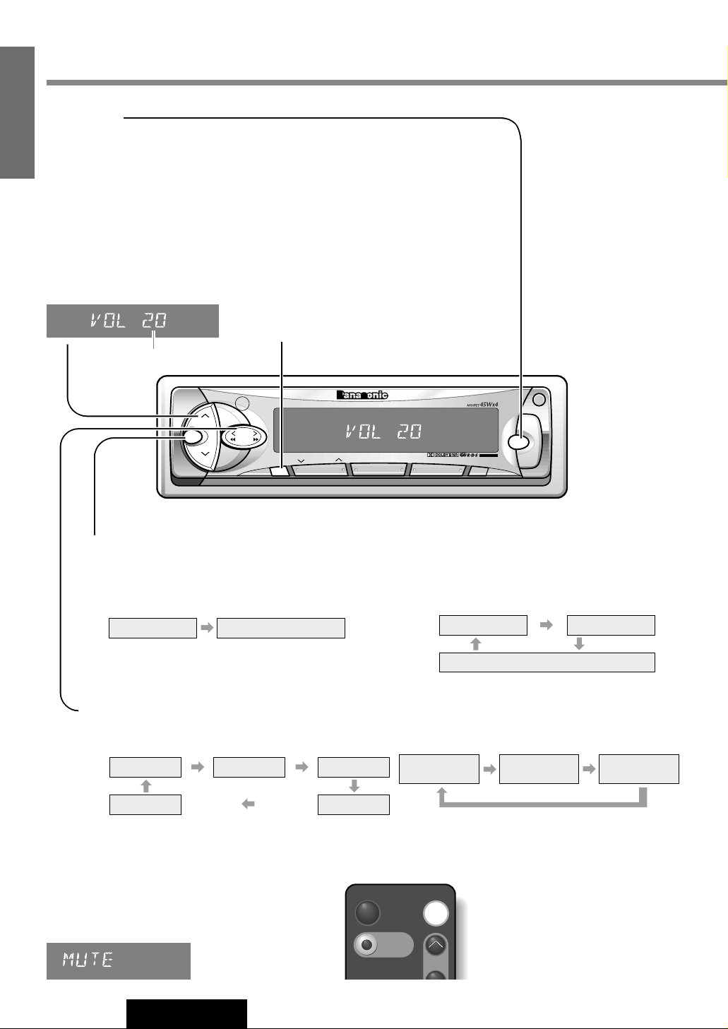
Volume Level (0 to 40)
Power and Sound Controls
Power
Turn the key in the ignition until the accessory
indicator lights.
Power on : Press [SOURCE] (PWR).
Power off : Press [SOURCE] (PWR) again
and hold.
Volume
[}VOL] : Up
[{VOL] : Down
Press and hold for rapid adjustment.
Anti-Volume-Blast
Circuit
When the power is switched
off and on again, the volume
slowly rises to the previous
level.
The anti-volume-blast circuit
will not work when the volume level is set lower than
position 20 on the display.
Level Meter
Note: When the power is switched on
for the first time, a demonstration message appears on the display.
To cancel this display, press [DISP].
Mute
(Only for a Remote control)
Press [MUTE] to mute the sound completely.
Press [MUTE] again to cancel.
Display Control Mode
q
Press and hold [SEL] to change to the display
control mode. (“PATTERN” appears on the display.)
w
Press [SEL] during the display control mode
to change the display control mode as follows.
e
Press [[TUNE] to change each setting. Select your desired setting. ([]TUNE] : opposite direction)
Dimmer
Note: The display will be back to the previous mode
with no operation for 5 seconds.
Pattern 1
Pattern off Pattern 4
Pattern 2 Pattern 3
Regular Mode Display Control Mode
Level Meter Dimmer
Panel Removal Alarm*
* See page 23.
Dimmer 3
(Brighter)
Dimmer 2
(Center)
Dimmer 1
(Darker)
PWR
(ATT)
MUTE
MODE
VOL
Page 9
VOL
SEL
SUB·W
OPEN
SOURCE
TA
PWR
REG
TUNE
TRACK
BAND
S•HDB
DISC
PRG
AUTO·P
REMOTE
CQ-FX421N
EON
E
PTY
E
CT
CASSETTE RECEIVER WITH CHANGER CONTROL
CT
REPEAT
SCAN
RANDOM
MONO/LOC
DISP
PTY
123 4
MTL NR TPS B·S REP
56
AF
SEL
VOL
S•HDB
9
CQ-FX421/FX321N
4
E
N
G
L
I
S
H
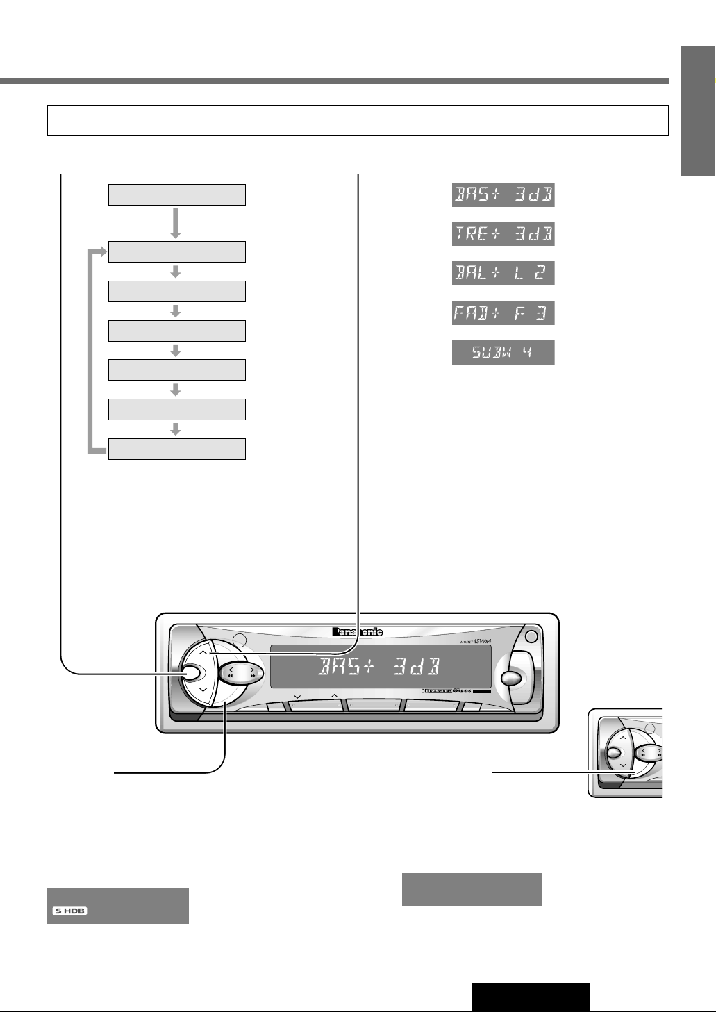
Loudness
(Only for CQ-FX321N)
Press and hold [LOUD] for more than 2 seconds to
enhance bass and treble tones at low or medium volume.
Press [LOUD] again to cancel.
LOUD
S•HDB
(Super High Definition Bass)
(Only for CQ-FX421N)
Especially for music, the bass-sound will be more powerful.
Press [S • HDB] to be able to listen to high-definition bass.
Press [S • HDB] again to cancel.
Note: If no operation takes place for more than 5 seconds in the audio mode (2 seconds in Volume mode), the
display returns to Regular Mode.
w
Press [}VOL] or [{VOL] to change each level.
Bass
(–12 to +12)
Treble
(-12 to +12)
Balance
(Left / Right: 1 to 15)
Fader
(Front / Rear: 1 to 15)
Subwoofer-Volume
(For CQ-FX421N)
Adjustable range:
MUTE(0) to 8
Note: If no operation takes place for more than 5
seconds in audio mode (2 seconds in Volume
mode), the display return to Regular Mode.
Audio Mode (Bass/Treble/Balance/Fader/Sub-Woofer)
q Press [SEL] to select the audio mode.
Regular Mode
Volume
Bass
Treble
Balance
Fader
Sub-Woofer
(Only for CQ-FX421N)
VOL
SEL
TUNE
TRACK
BAND
S•HDB
PRG
AUTO·P
REMOTE
LOUD
Page 10
Radio Basics
10
CQ-FX421/FX321N
5
E
N
G
L
I
S
H
VOL
SEL
SUB·W
OPEN
SOURCE
TA
PWR
REG
TUNE
TRACK
BAND
S•HDB
DISC
PRG
AUTO·P
REMOTE
CQ-FX421N
EON
E
PTY
E
CT
CASSETTE RECEIVER WITH CHANGER CONTROL
CT
REPEAT
SCAN
RANDOM
MONO/LOC
DISP
PTY
123 4
MTL NR TPS B·S REP
56
AF
SOURCE
TUNE
TRACK
BAND
PTY
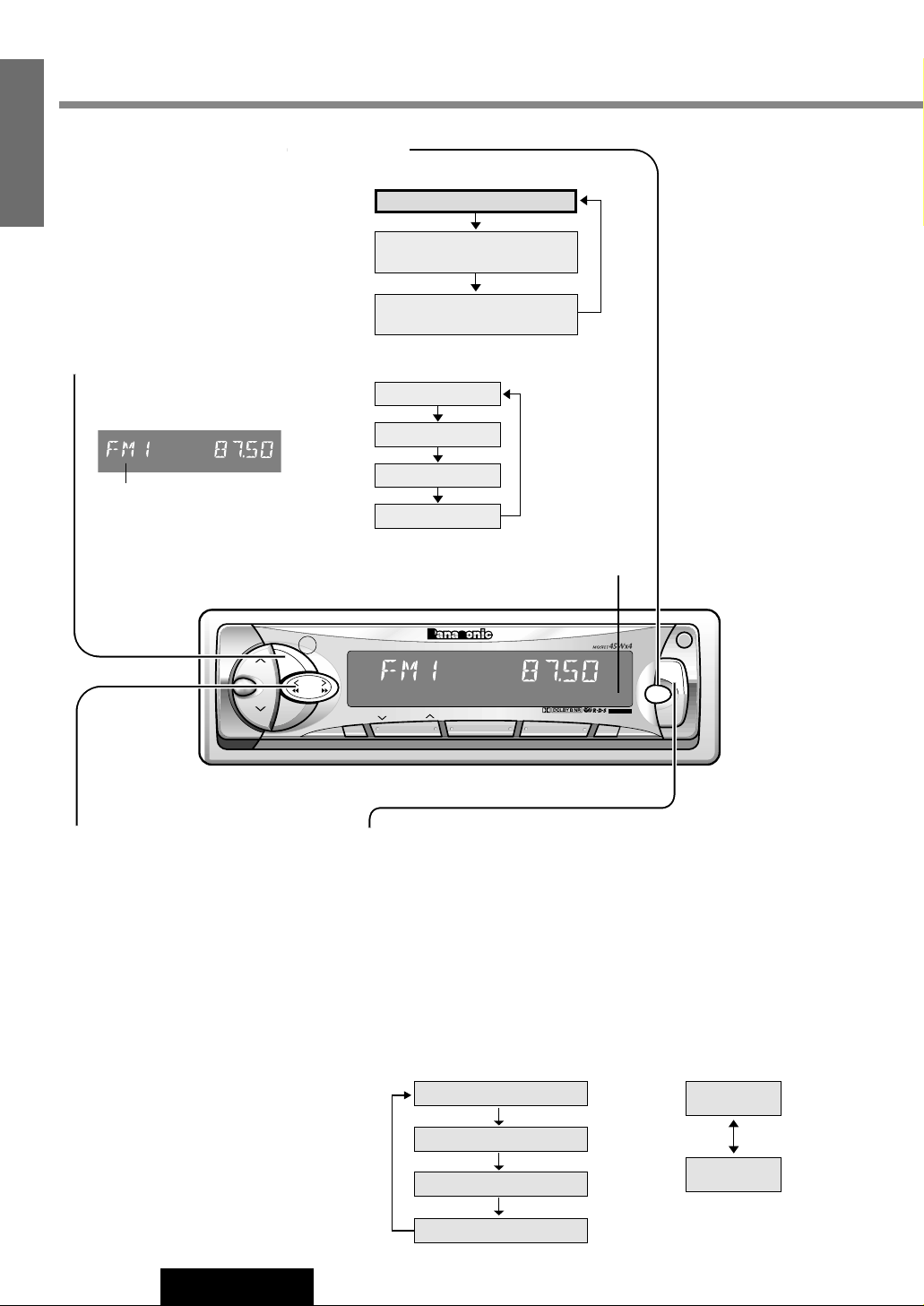
r Mono/Local Selection (MONO/LOC)
MONO : Noise is significantly decreased when weak signals are
received from an FM broadcast station.
LOCAL : Only strong signals of stations are searched in seek tuning,
while at the LOCAL OFF setting, relatively weak signals are
also searched.
e Manual Tuning
[[TUNE] : Higher frequency.
[]TUNE] : Lower frequency.
Seek Tuning
Press and hold
[[TUNE] : Higher frequency.
[]TUNE] : Lower frequency.
Tuning will automatically stop when
the signals of the next broadcast
station are received.
q Mode Selection
Press [SOURCE] to change to the
radio mode.
Radio
Cassette Tape Player
(When a tape is inserted)
CD changer control
(When a CD changer is connected)
FM1
FM2
FM3
AM (LW/MW)
w Band
Press [BAND] to change the
bands.
FM stereo indicator
FM broadcasts
Press and hold [PTY] (MONO/
LOC) to change the mode.
Release when at the desired point.
MONO OFF / LOCAL OFF
LOCAL OFF
MONO ON / LOCAL OFF
MONO ON / LOCAL ON
MONO OFF / LOCAL ON
LOCAL ON
AM broadcast
Press and hold [PTY] (MONO/LOC)
to switch LOCAL mode on and off.
Band
ST
(SOURCE)
Page 11
11
CQ-FX421/FX321N
6
E
N
G
L
I
S
H
VOL
SEL
SUB·W
OPEN
SOURCE
TA
PWR
REG
TUNE
TRACK
BAND
S•HDB
DISC
PRG
AUTO·P
REMOTE
CQ-FX421N
EON
E
PTY
E
CT
CASSETTE RECEIVER WITH CHANGER CONTROL
CT
REPEAT
SCAN
RANDOM
MONO/LOC
DISP
PTY
123 4
MTL NR TPS B·S REP
56
AF
BAND
12
MTL NR
34
TPS B·S REP
56
w
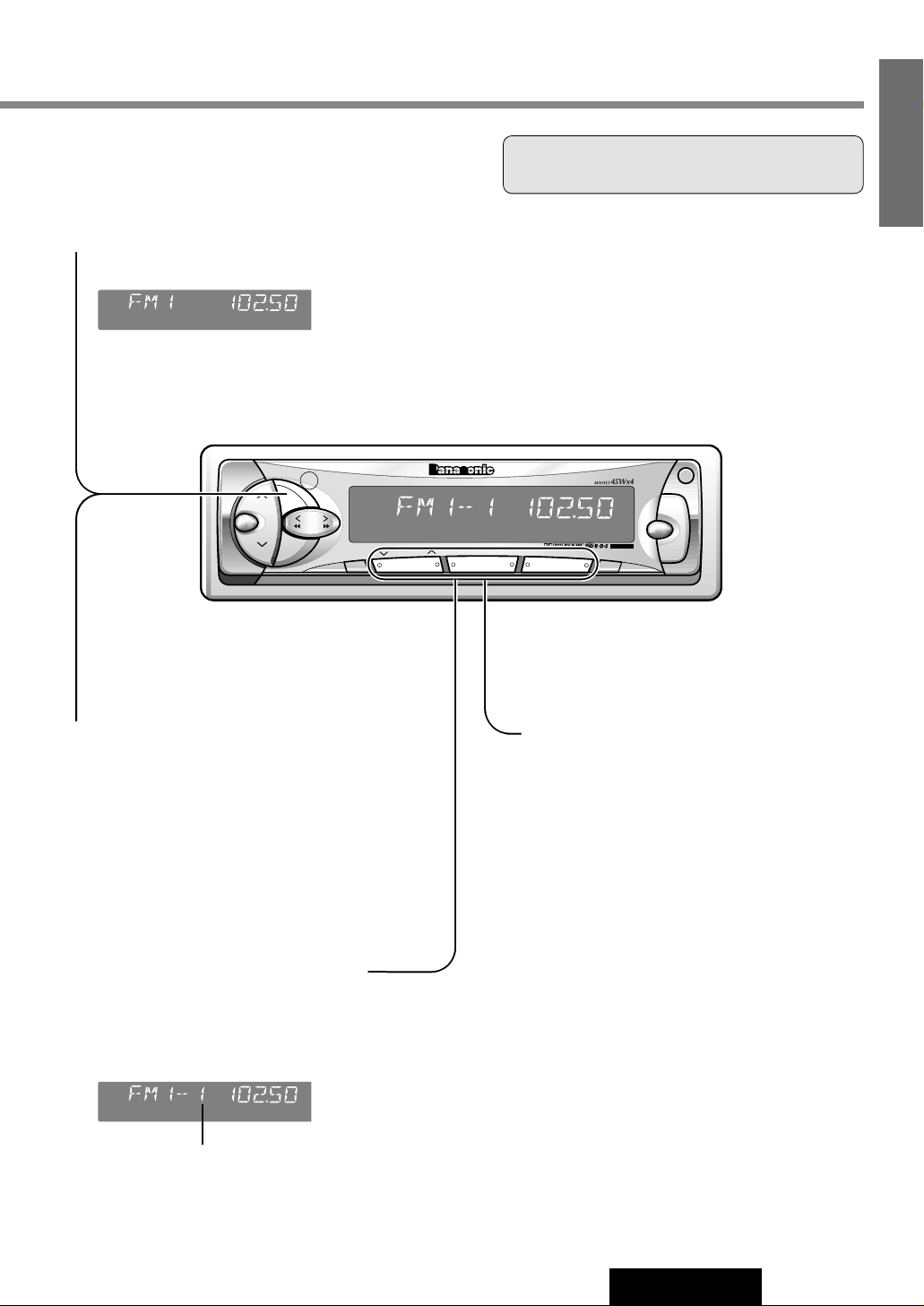
Auto Station Preset
Press and hold [BAND] (AUTO • P) for more than
2 seconds (Auto Preset Memory).
¡The 6 strongest available stations will be auto-
matically saved in the memory under preset buttons [1] to [6].
¡Once set, the preset stations are sequentially
scanned for 5 seconds each.
Manual Station Preset
q Use manual or seek tuning to find a station.
(a page 10)
w Press and hold one of the preset buttons [1] to
[6] until the display blinks once.
(AUTO • P)
Preset Station Setting
Up to 6 stations each can be saved in the FM1, FM2, FM3 and
AM (LW/MW) preset station memories.
q Band
Press [BAND] to select a desired band. (a Page 10)
Caution: To ensure safety, never attempt to preset
stations while you are driving.
e Tuning in a Preset
Station
Press the corresponding preset button [1] to
[6] to tune in a preset station.
Note: You can change the memory preset-
ting by repeating the above procedure.
Preset Number
Page 12
12
CQ-FX421/FX321N
7
E
N
G
L
I
S
H
RDS (Radio Data System)
RDS Basics
The following functions are available when receiving RDS stations.
PS Display
(Program Service name)
The name of station is displayed
instead of the frequency.
CT Service
(Clock Time)
When receiving an RDS station, the
CT (Clock Time) service automatically
adjusts the time.
"NO CT" is displayed in areas where
CT service is not available.
(a Page 15 for Clock Set)
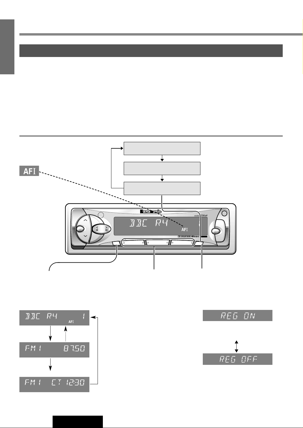
AF
(Alternative Frequency list)
When reception is poor, an RDS station broadcasting the same program
is tuned in automatically.
Display Change
Press [DISP] to change the display
as follows.
Auto Preset Memory
Auto preset of RDS stations works
only when AF mode is on.
Best Station Research
Best Station Research is automatically
activated to store the station with the
best reception for each preset button.
PI (Program Identification) Seek
If Best Station Research does not
work properly and reception is poor
when tuning in a preset station, press
the same preset button again. PI
Seek will search an AF station with
good reception.
REG (Region) Mode
Changes the selection range of AF,
Best Station Research and PI Seek.
Press and hold [AF] (REG) when AF
mode is on.
The frequency is changed only for
programs within the region.
The frequency is changed also for
programs outside the region.
AF Mode
Press [AF] to select one of the
following AF modes:
VOL
SEL
SUB·W
OPEN
SOURCE
TA
PWR
REG
TUNE
TRACK
BAND
S•HDB
DISC
PRG
AUTO·P
REMOTE
CQ-FX421N
EON
E
PTY
E
CT
CASSETTE RECEIVER WITH CHANGER CONTROL
CT
REPEAT
SCAN
RANDOM
MONO/LOC
DISP
PTY
123 4
MTL NR TPS B·S REP
56
AF
DISP
12
MTL NR
34
TPS B·S REP
56
AF
Low level AF operating sensitivity.
High level AF operating sensitivity.
When the AF network of an RDS
station is not required
AF 1 Mode
(Default)
AF 2 Mode
AF OFF Mode
PS (Program Service Name)(Default)
3 seconds
Frequency
CT (Clock Time)
Page 13
Traffic Announcements
TA Volume Set
(Volume Level : 0 to 40)
Press [}VOL] or [{VOL] while receiving traffic
announcements .
The TA volume differs from the regular volume (by up
to 5 levels).
TA in Tape/CD Changer Mode
When TA is on, tape or CD changer playback will be
interrupted by FM traffic announcements.
Muting in TA Mode
To listen only to Traffic Announcements while muting,
press and hold [TA] for more than 2 seconds.
To cancel the muting TA on mode (muting in TA mode /
TA mode), take either following two.
¡Press [TA] again.
¡Press [}VOL] several times.
Note: To switch to TA off, press [TA] again and hold for
more than 2 seconds.
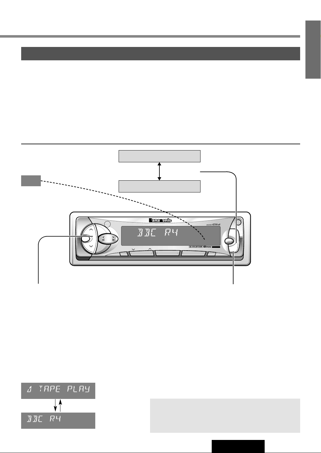
TP Auto Search
When reception of a TP station is poor, TP Auto Search
will automatically search for a TP station with better
reception.
TA Mode
Press [TA] to switch TA mode on
and off.
TA on
TA off
Seek and Preset Station
TP Seek Tuning
Seek tunes only TP stations. (a Page 10)
Auto TP Station Preset
The 6 strongest TP stations are saved in memory. (a Page 11)
Tuning in a TP Preset Station (a Page 11)
13
CQ-FX421/FX321N
8
E
N
G
L
I
S
H
VOL
SEL
SUB·W
OPEN
SOURCE
TA
PWR
REG
TUNE
TRACK
BAND
S•HDB
DISC
PRG
AUTO·P
REMOTE
CQ-FX421N
EON
E
PTY
E
CT
CASSETTE RECEIVER WITH CHANGER CONTROL
CT
REPEAT
SCAN
RANDOM
MONO/LOC
DISP
PTY
123 4
MTL NR TPS B·S REP
56
AF
TA
SEL
VOL
Information End
TP
AF
EON
TAon
TP
AF
EON
TAon
TAon
Some RDS FM stations periodically
provide traffic information.
TP
(Traffic Program identification)
Broadcasting of traffic information
TA
(Traffic Announcements identification)
Radio announcements on traffic conditions
Page 14
RDS (Radio Data System) (continued)
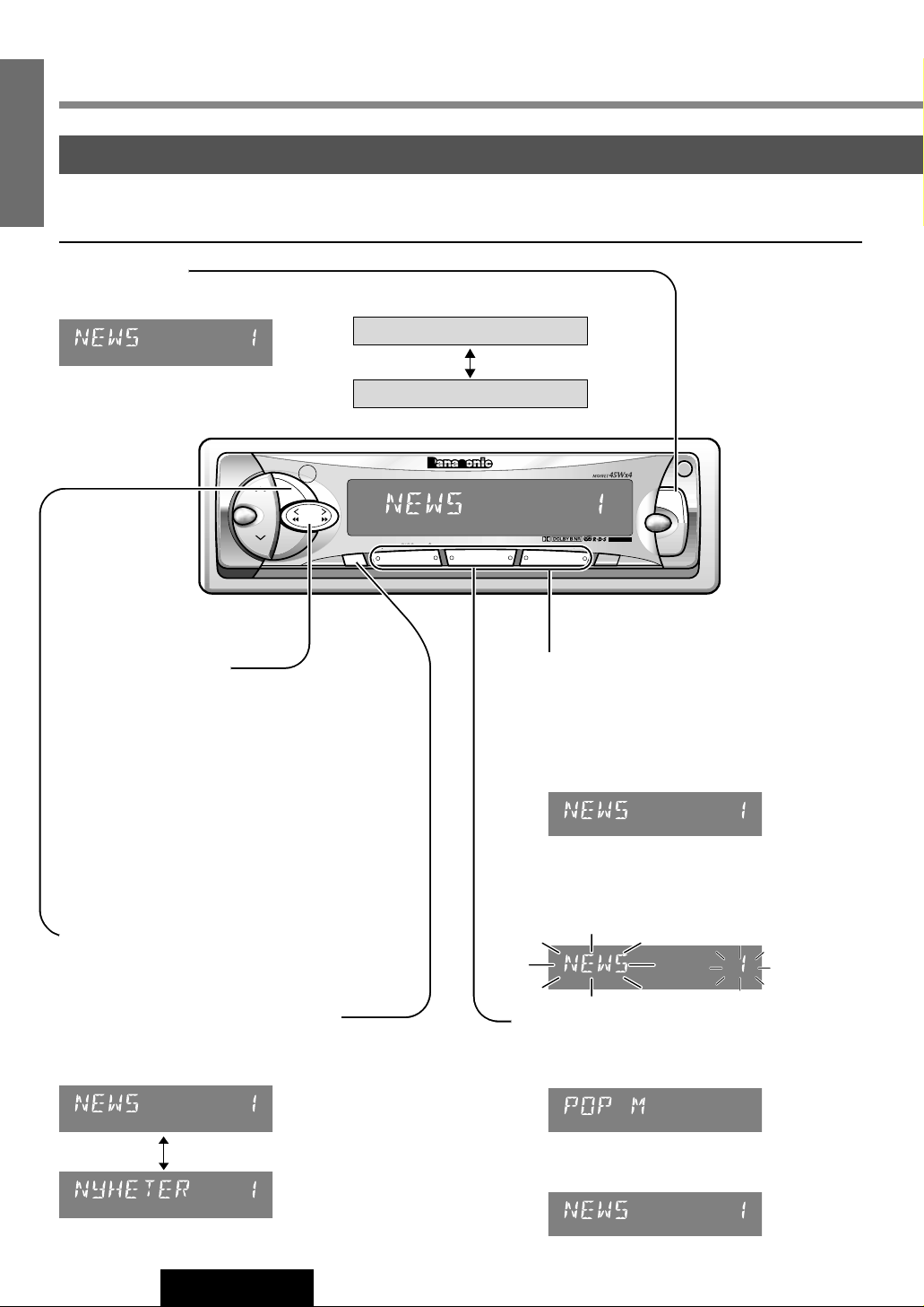
PTY Reception
(Program Type)
RDS FM stations provide a program type identification signal.
Example: news, rock, classical music, etc.
PTY Mode
Press [PTY] to switch PTY display mode on or off.
PTY Search
q
Select a program type by pressing the preset
button.
The preset program type appears on the display
for 5 seconds.
(Example) Press preset button [1].
w
Press the same preset button again (or press
[BAND]) to tune in the desired program type
station.
(Example) Press preset button [1] again.
PTY Preset Change
q
Select a program type by using PTY Selection or
pressing PTY Preset buttons.
w
Press and hold one of the buttons [1] to [6].
(Example) Press and hold preset button [2].
PTY
PTY
PTY
PTY
14
CQ-FX421/FX321N
9
E
N
G
L
I
S
H
PTY on
PTY off
VOL
SEL
SUB·W
OPEN
SOURCE
TA
PWR
REG
TUNE
TRACK
BAND
S•HDB
DISC
PRG
AUTO·P
REMOTE
CQ-FX421N
EON
E
PTY
E
CT
CASSETTE RECEIVER WITH CHANGER CONTROL
CT
REPEAT
SCAN
RANDOM
MONO/LOC
DISP
PTY
123 4
MTL NR TPS B·S REP
56
AF
TUNE
TRACK
DISP
BAND
12
MTL NR
34
TPS B·S REP
56
PTY
<English>
<Swedish>
When there is no corresponding program
type, “NO PTY” is display
PTY
PTY
PTY
PTY
PTY Selection
q
Press [[TUNE] to change the program type
as follows. ([]TUNE] : opposite direction)
w
Select the desired program and press [BAND].
Seek will start to tune in to a station broadcasting the selected program type.
PTY display in Swedish
Press [DISP] to switch the PTY display
language as follows.
SPEECH / MUSIC / NEWS / AFFAIRS /
INFO / SPORT / EDUCATE / DRAMA /
CULTURES / SCIENCE / VARIED / POP M /
ROCK M / M.O.R.M / LIGHT M / CLASSICS /
OTHER M / WEATHER / FINANCE / CHILDREN /
SOCIAL A / RELIGION / PHONE IN / TRAVEL /
LEISURE / JAZZ / COUNTRY / NATIONAL /
OLDIES / FOLK M / DOCUMENT /
Page 15
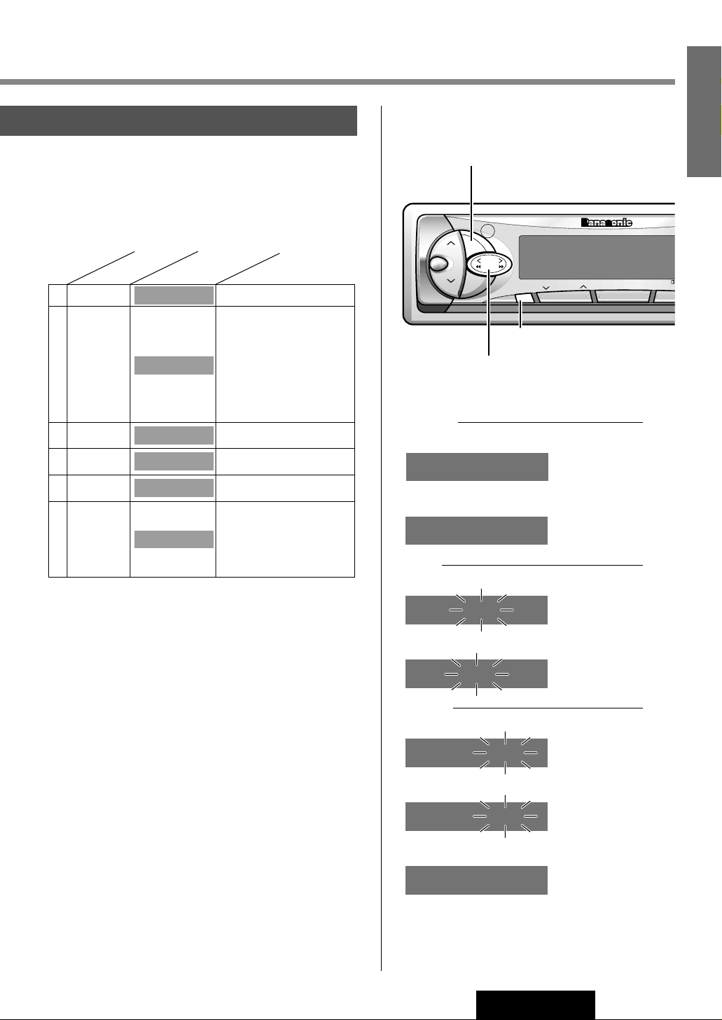
PTY Type Preset
Program types are stored in memory under preset buttons
[1] to [6] as shown in the table below.
To tune in the desired program type, press any of preset buttons [1] to [6].
EON
(Enhanced Other Networks)
When EON data is received, the EON indicator lights and the
TA and AF functions are expanded as follows.
TA : Traffic information from the current and other network
stations can be received.
AF : The frequency list of preset RDS stations is updated by
EON data.
EON enables the radio to make fuller use of RDS information.
It constantly updates the AF list of preset stations, including
that currently tuned in to. For example, if you preset a station far from home, you will later be able to receive the same
station at an alternative frequency, or any other station serving the same program. EON also keeps track of locally available TP stations for quick reception.
Emergency Announcement
Reception
When an emergency announcement is broadcast, the unit is
automatically switched to receiving that broadcast. If this
happens in a mode other than radio mode (tape mode, CD
Changer mode) or in Muting in TA mode, "ALARM" blinks on
the display.
Preset No.
Program Type
Display
AFFAIRS / INFO
EDUCATE / DRAMA
CULTURES / SCIENCE
VARIED / WEATHER
FINANCE / CHILDREN
SOCIAL A / RELIGION
PHONE IN / TRAVEL
LEISURE / DOCUMENT
ROCK M / M.O.R.M
LIGHT M / OTHER M
JAZZ / COUNTRY
NATIONAL / OLDIES
FOLK M
News NEWS1
Speech2
Sport SPORT3
Pop. Music
POP.M4
Classic
Music
CLASSICS5
Other
Music
6
When RDS CT service is not available, set the
clock as follows.
AM Band
q Press [BAND] to change to AM band.
w Press [DISP].
Hours
e Press and hold [DISP].
r Press [[TUNE] or []TUNE].
Minutes
t Press [DISP].
y Press [[TUNE] or []TUNE].
u Press [DISP].
Note: Hold [[TUNE] or []TUNE] to
change numbers rapidly.
(end)
10:35
(minute set)
10:35
(minute blinks)
10:00
(hour set)
10:00
(hour blinks)
0:00
(Clock display)
NO CT
(AM band)
AM 1305
Clock Set
15
CQ-FX421/FX321N
10
E
N
G
L
I
S
H
VOL
SEL
TUNE
TRACK
BAND
S•HDB
DISC
PRG
AUTO·P
REMOTE
CQ-FX421N
CASSETTE RECEIVER WITH CHANGER CONTROL
CT
SCAN
RANDOM
DISP
123 4
MTL NR TPS B·S
5
TUNE
TRACK
DISP
BAND
BAND
DISP (CT)
][ TUNE
NNEEWWSS 11
SSPPEEEECCHH 22
SSPPOORRTT 33
PPOOPP MM 44
CCLLAASSSSIICCSS 55
MMUUSSIICC 66
Page 16
16
CQ-FX421/FX321N
11
E
N
G
L
I
S
H
CD
MD
Cassette Tape Player Basics
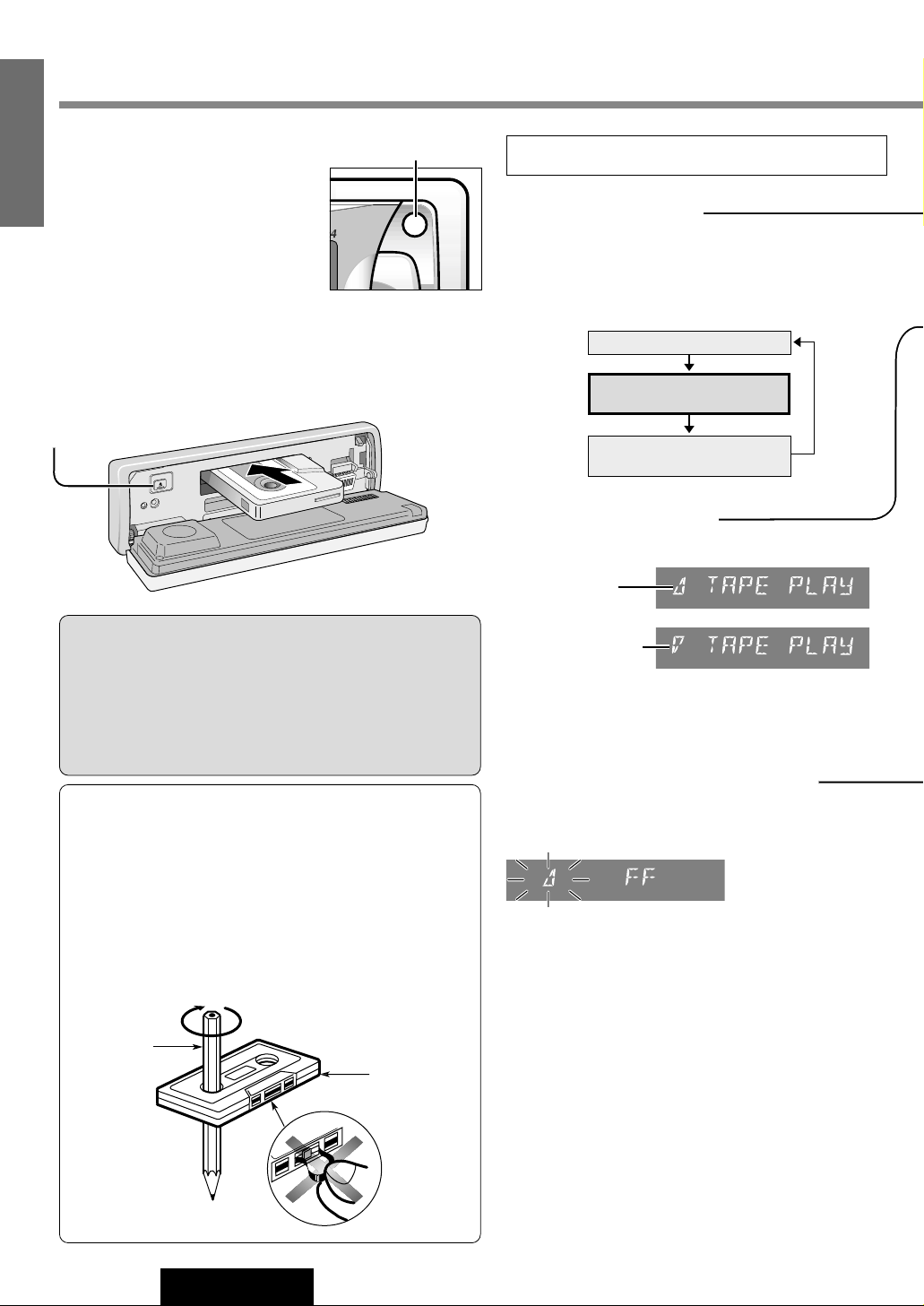
Tape Insert and Playback
q Open the front panel.
w Insert a cassette tape.
e Close the front panel manually.
Play back will start automatically.
Stop and Tape Eject
q Open the front panel.
w Press [u] to stop tape play and eject the cassette tape.
e Close the front panel manually.
Listening to a Cassette Tape
Rewind and Fast Forward
Press [1TRACK] or [2 TRACK] to activate
rewind or fast forward of the tape.
Press [BAND](PRG) to resume the tape play.
Play Side Change
Press [BAND](PRG) to reverse.
Top Side Playing
Bottom Side Playing
Source
Radio
Cassette Tape Player
(When a Tape is inserted)
CD changer control
(When a CD changer is connected)
Note: To maintain your cassette player in top condition, avoid
using tapes that are longer than 90 minutes (C-90).
Notes on Cassette Tape
Tape Slack:
Use a pencil or similar object to take up the slack as shown. If
a loose tape is used, this may result in the tape becoming tangled in the rotating parts of the unit.
Mode Selection
Press [SOURCE] to change to Cassette tape play
mode.
OPEN
PWR
MONO/LOC
PTY
OPEN
Eject
Cautions:
¡When the front panel is opened, do not force it down and
do not put anything on it since these may result in damage
to the unit.
¡When ejecting a cassette tape, do not close the front panel
until the cassette tape is ejected and removed from the
cassette slot completely.
Exposed end
(Open end)
Pencil
Do not touch or
pull out the tape.
Open
Page 17
VOL
SEL
SUB·W
OPEN
SOURCE
TA
PWR
REG
TUNE
TRACK
BAND
S•HDB
DISC
PRG
AUTO·P
REMOTE
CQ-FX421N
EON
E
PTY
E
CT
CASSETTE RECEIVER WITH CHANGER CONTROL
CT
REPEAT
SCAN
RANDOM
MONO/LOC
DISP
PTY
123 4
MTL NR TPS B·S REP
56
AF
12
MTL NR
3
TPS B·S REP
56
SOURCE
TUNE
TRACK
BAND
17
CQ-FX421/FX321N
12
E
N
G
L
I
S
H
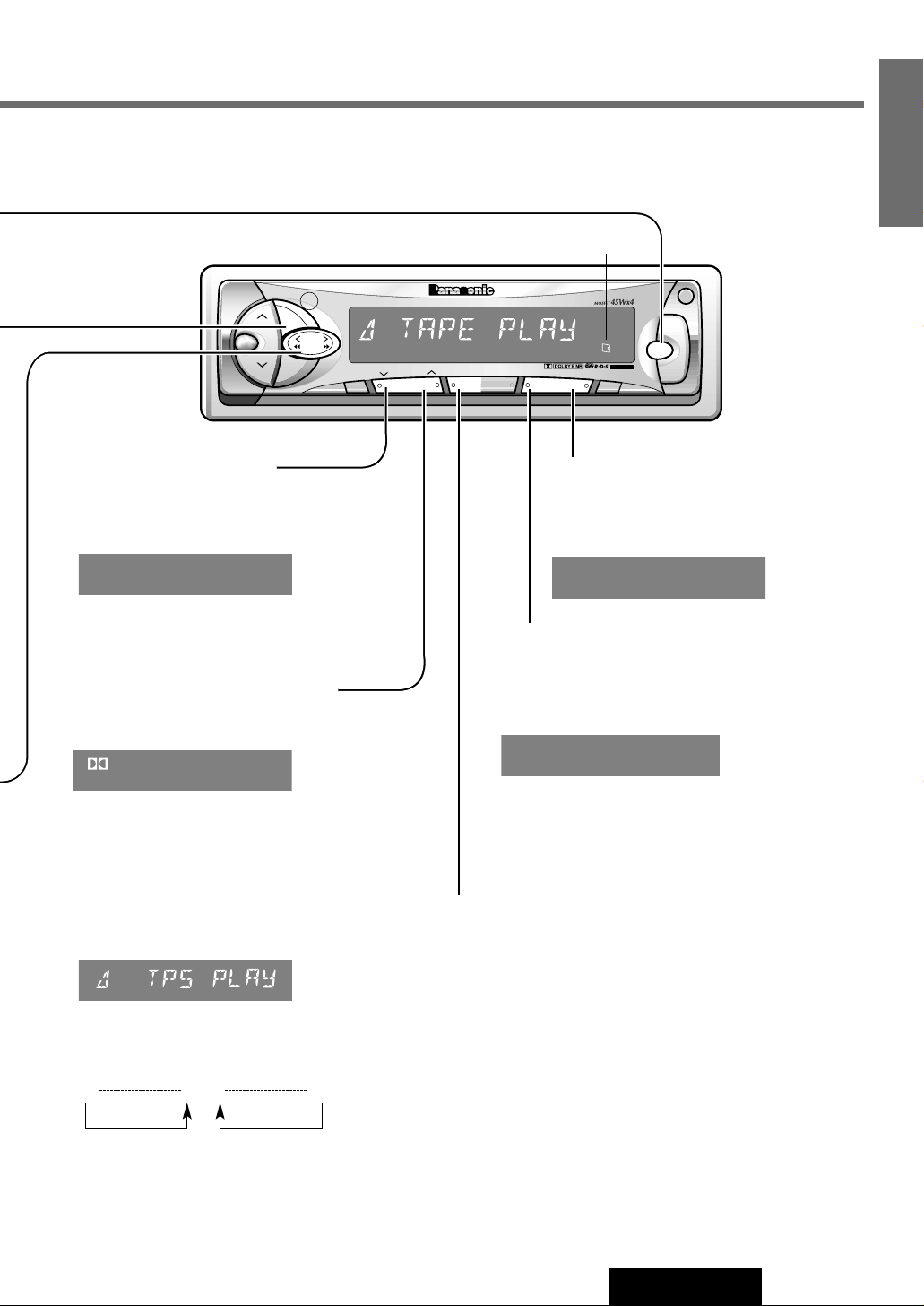
Metal Tape Mode
¡Press [1](MTL) when playing metal or chromium
dioxide (CrO
2
) tapes.
¡Press [1](MTL) again to cancel.
Note: Playing non-metal tapes in MTL mode causes
high frequency imbalance, which affects tone quality.
Dolby Noise Reduction
¡Press [2](NR) to set the Dolby B NR mode.
¡Press [2](NR) again to cancel.
Note: Set the Dolby B NR mode when playing back a
tape recorded with Dolby B Noise Reduction.
Repeat Play
¡Press [6](REP) to repeat the current
program.
¡Press [6](REP) again to cancel.
Blank Skip
¡Press [5](B • S) to skip unrecorded portions
longer than 15 seconds on the tape.
¡Press [5](B • S) again to cancel.
Note: When repeat is on, the blank skip does
not work because the repeat has priority over
the blank skip.
B-SKIP
REP
Tape Program Search (TPS) Operation
q Press [3](TPS) to activate the Tape Program Search mode.
w To select a desired program, press [2TRACK] or [1TRACK]
corresponding times to go forward (up to 9) or backward (up to 8).
e Press [3](TPS) again to cancel.
(Fast forward:)
1 s9
(Rewind:)
8t 0
Notes:
The TPS mode may not work correctly in the following cases. This,
however, does not mean that the unit is defective.
¡There is an interval less than 3 seconds or having a high level of
noise or hum between programs.
¡There is particularly low-level passage during the program.
Lights when a tape is in the deck
MTL
B
Page 18
18
CQ-FX421/FX321N
13
E
N
G
L
I
S
H
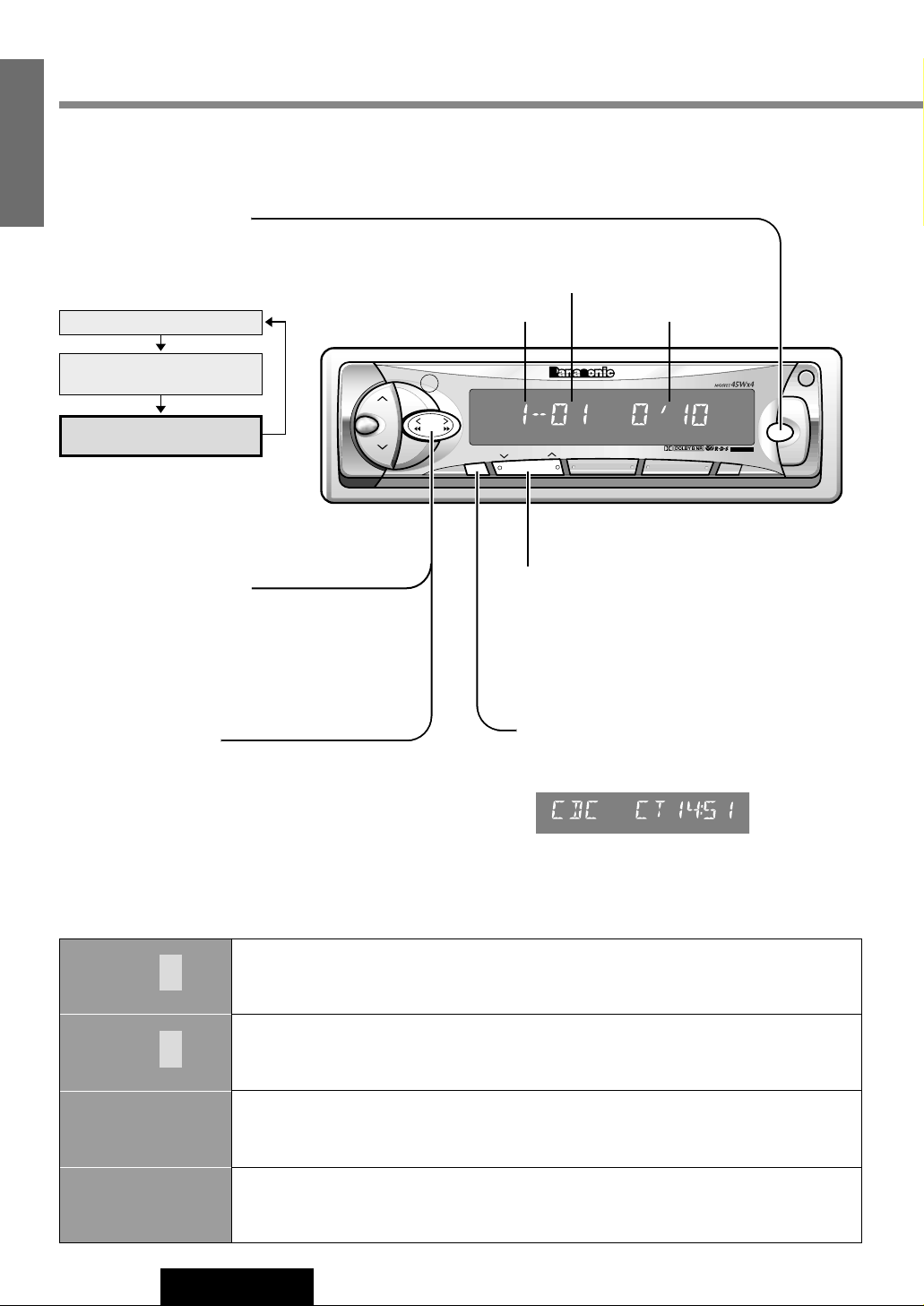
CD Changer Basics
Track Selection
[fTRACK] : Advance to the next track.
[aTRACK] : Back to beginning of the current
track.
Back to previous track.
(Press twice)
Track Search
Press and hold
[fTRACK] : Fast forward
[aTRACK] : Fast backward
Release to resume the regular CD
changer play.
Display Change
¡Press [DISP] to switch to the clock display.
¡Press again to cancel.
Mode Selection
Press [SOURCE] to change to the
CD changer mode.
CDC 0000
CDC E3
CDC E2
c
DISC No.
CDC E1
c
DISC No.
Appears on the display when the compact disc is dirty or inverted. Select the next available
compact disc.
Appears on the display when compact disc is scratched.
Select the next available compact disc.
Error Display Messages
Appears on the display when the unit stops operating for some reason.
Press the reset switch on the CD changer.
Appears on the display when there is no disc in the magazine.
VOL
SEL
SUB·W
OPEN
SOURCE
TA
PWR
REG
TUNE
TRACK
BAND
S•HDB
DISC
PRG
AUTO·P
REMOTE
CQ-FX421N
EON
E
PTY
E
CT
CASSETTE RECEIVER WITH CHANGER CONTROL
CT
REPEAT
SCAN
RANDOM
MONO/LOC
DISP
PTY
123 4
MTL NR TPS B·S REP
56
AF
SOURCE
TUNE
TRACK
DISP
12
MTL NR
Track Number
Disc Number Playing Time
Source
Radio
Cassette Tape Player
(When a Tape is inserted)
CD changer control
(When a CD changer is connected)
Disc Selection
[1] ({DISC): Previous disc.
[2] (}DISC): Next disc.
Page 19
19
CQ-FX421/FX321N
14
E
N
G
L
I
S
H
VOL
SEL
SUB·W
OPEN
SOURCE
TA
PWR
REG
TUNE
TRACK
BAND
S•HDB
DISC
PRG
AUTO·P
REMOTE
CQ-FX421N
EON
E
PTY
E
CT
CASSETTE RECEIVER WITH CHANGER CONTROL
CT
REPEAT
SCAN
RANDOM
MONO/LOC
DISP
PTY
123 4
MTL NR TPS B·S REP
56
AF
34
TPS B·S REP
56
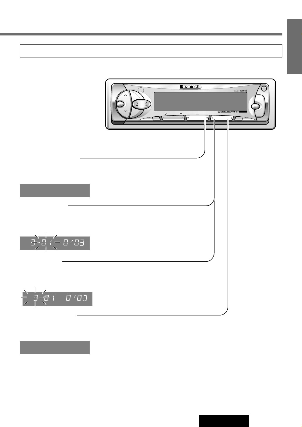
Track Random
¡Press [4] (RANDOM).
All tracks on all discs in the magazine are played in random order.
¡Press again to cancel.
Track Scan
¡Press [5] (SCAN).
The first 10 seconds of each track on the disc are played in sequence.
¡Press again to cancel.
Disc Scan
¡Press and hold [5] (SCAN) for more than 2 seconds.
The first track of all discs in the magazines is played for 10 seconds each.
¡Press again to cancel.
Track Repeat
¡Press [6] (REP).
The current track is repeated.
¡Press again to cancel.
Various Way of Listening
Note: The CD Changer functions are designed for an optional CD changer unit.
RAND
REP
Page 20
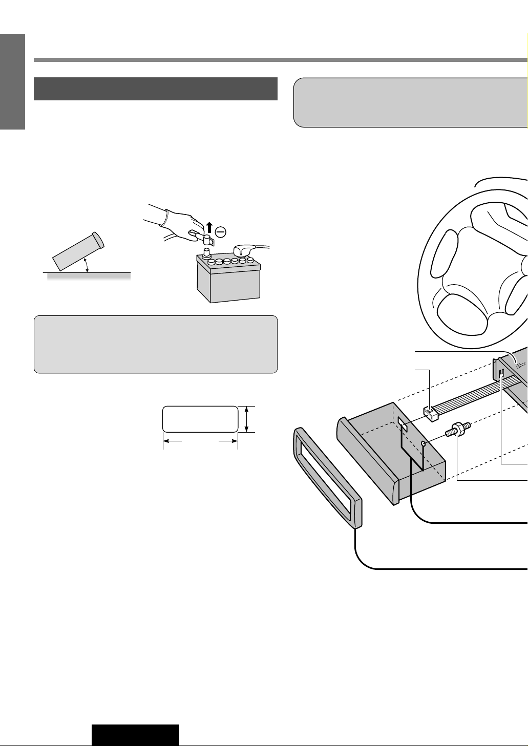
Caution: Do not disconnect the battery terminals of a car
with trip or navigational computer since all user settings
stored in memory will be lost. Instead take extra care with
installing the unit to prevent shorts.
Installation
Preparation
20
CQ-FX421/FX321N
15
E
N
G
L
I
S
H
¡Before installation, check the radio operation with antenna and
speakers.
¡Disconnect the cable from the negative (–) battery terminal
(see caution below).
¡Unit should be installed in a horizontal position with the front
end up at a convenient angle, but not more than 30°.
Dashboard Installation
Installation Opening
The unit can be installed in
any dashboard having an
opening as shown at right.
The dashboard should be
4.5 mm - 6 mm thick in order to be able to support the unit.
Installation Precautions
This product should be installed by a professional installer, if possible.
In case of difficulty, please consult your nearest authorized
Panasonic Service Center.
1. This system is to be used only in a 12-volt, DC battery system
(car) with negative ground.
2. Follow the electrical connections carefully (a Page 24).
Failure to do so may result in damage to the unit.
3. Connect the power lead (red) after all other connections are
made.
4. Be sure to connect the battery lead (yellow) to the positive terminal (+) of the battery or fuse block (BAT) terminal.
5. Insulate all exposed wires to prevent short circuiting.
6. Secure all loose wires after installing the unit.
7. Please carefully read the operating and installation instructions
of the respective equipment before connecting it to this unit.
First complete the electrical connections, and then
check them for correctness.(a Page 24)
Lock Lever (C)
Power Connector e
¡We strongly recommend that you wear gloves
for installation work to protect yourself from
injuries.
30° or less
182 mm
53 mm
Page 21
Q’tyDiagramItemNo.
1
2
3
4
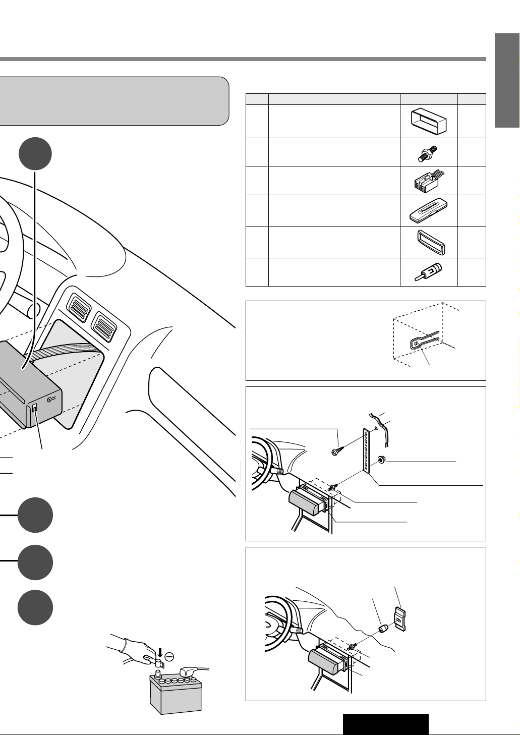
Supplied Hardware
Fire Wall of Car
Hex. Nut (Option)
Rear Support Strap (Option)
wMounting Bolt
qMounting Collar
Tapping Screw (Option)
3 mmø
(a) Using the Rear Support Strap (Option)
Rubber Cushion
(Option)
wMounting Bolt
qMounting Collar
Rear Support Bracket
(Provided on the car)
(b) Using the Rubber Cushion (Option)
Make sure that the lock lever (C)
is flush with the mounting collar
(not projecting outward).
Lock Lever
Mounting Tabs
Mounting Bolt w
Secure the rear of the unit.
After fixing Mounting Bolt w and Power
Connector e, fix the rear of the unit to
the car body by either method (a) or (b)
shown at right.
Insert Trim Plate t.
After installation reconnect the
negative (–) battery terminal.
Insert Mounting Collar q into
the dashboard, and bend the
mounting tabs out with a screwdriver.
¡When bending the mounting tab of the mount-
ing collar with a screwdriver, be careful not to
injure your hands and fingers.
q
w
e
r
t
y
Mounting Collar
Mounting Bolt (5 mmø)
Power Connector
Removable Face Plate Case
Trim Plate
ISO Antenna Adapter
1
1
1
1
1
1
21
CQ-FX421/FX321N
16
E
N
G
L
I
S
H
Page 22
22
CQ-FX421/FX321N
17
E
N
G
L
I
S
H
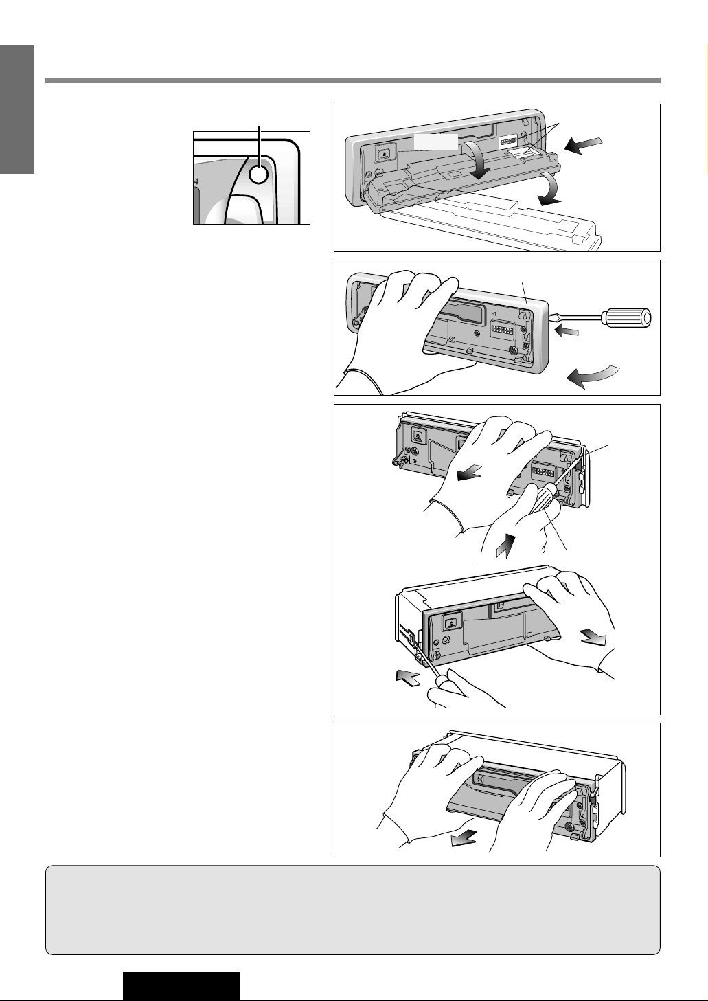
To Remove the Unit
q
Remove the removable
face plate.
(a) Open the face plate.
(b) Push the face plate
to either the right
or left, then pull it
out toward you.
e
Pull out the unit while pushing down the lock
lever with a screwdriver.
r
Remove the unit pulling with both hands.
Installation (continued)
1
2
Cautions:
¡Do not touch the contacts on the face plate or on the main unit, since this may result in poor electrical contacts.
¡If dirt or other foreign substances get on the contacts, wipe them off with clean and dry cloth.
¡Do not apply a strong downward force onto the face plate and do not put anything on it while it is open, or it might be
damaged.
q Open
Contact
w Push
e Pull out
tTrim Plate
Screwdriver
OPEN
PWR
MONO/LOC
PTY
w
Remove the trim plate t with a screwdriver.
OPEN
Open
Lock Lever
Screwdriver
Page 23
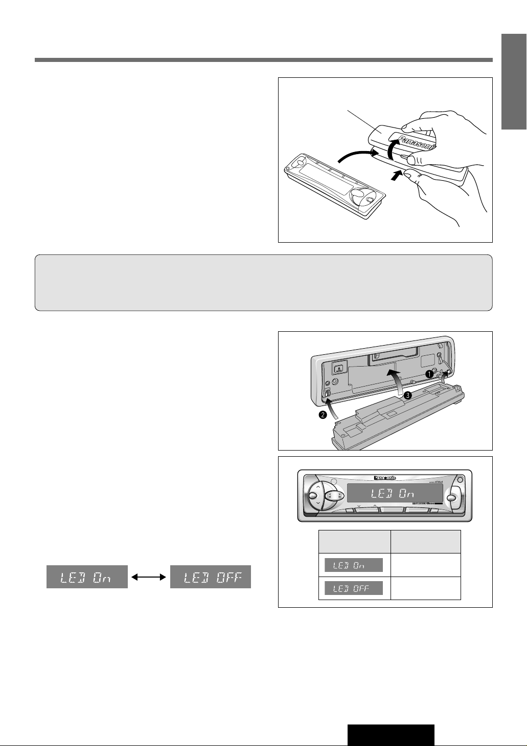
This unit is equipped with a removable face plate. Removing
this face plate makes the radio totally inoperable.
Place Removable Face Plate
into Case
q Switch off the power of the unit.
w Remove the removable face plate. (a Page 22)
e Gently press the bottom of the case and open the cover.
Place the face plate into the case and take it with you
when you leave the car.
Install Removable Face Plate
q Fit the face plate with its right or left hole on one of the
pins provided on the main unit.
w Fit the other hole on the other pin applying slight pres-
sure.
e Move the face plate up and down a few times to make
sure it is secure. Then close the front panel and press
down the right side of the face plate until it clicks into
place.
Panel Removal Alarm
This alarm sounds to warn you not to forget to remove the
panel before leaving your car.
q Press and hold [SEL] to change to display control
mode. (“PATTERN” is displayed.) (a Page 8)
w Press [SEL]. “LED On” or “LED OFF” is displayed.
e Press [] TUNE] or [[ TUNE] to turn the Panel
Removal alarm on or off (LED ON or OFF).
Anti-Theft System
Cautions:
¡This face plate is not water-proof. Do not expose it to water or excessive moisture.
¡Do not remove the face plate while driving your car.
¡Do not place the face plate on the dashboard or nearby areas where the temperature rises to high levels.
23
CQ-FX421/FX321N
18
E
N
G
L
I
S
H
r Removable Face Plate Case
VOL
SEL
SUB·W
OPEN
SOURCE
TA
PWR
R
E
G
TUNE
TRACK
BAND
S•HDB
DISC
P
R
G
A
U
T
O
·P
R
E
M
O
T
E
CQ-FX421N
EONEPTYECT
CASSETTE RECEIVER WITH CHANGER CONTROL
CT
R
E
P
E
A
T
SCAN
RANDOM
M
O
N
O
/L
O
C
DISP
PTY
123 4
MTL NR TPS B·S REP
56
AF
Panel Removal
Alarm
Display
ON
OFF
Page 24
Antenna
(If needed)
ePower
Connector
y ISO Antenna
Adapter
(White)
(Gray)
(Green)
(Violet)
Cassette Receiver
CQ-FX421N
R(Red)
L(White)
Preamp Out Connector (Rear)
Preamp Out Connector (Front)
(L)(White)
(R)(Red)
Extension Cord
(DIN/BATT/RCA/GND)
(Black)
CD Changer
CX-DP88N
Ground Lead
To a clean, bare metallic
part of the car chassis
Battery Lead
To the car battery,
continuous +12V DC
Sub-Woofer Out
(Monaural)
(Only for CQ-FX421N)
(Yellow)
Fuse (3A)
B (Brown)
Front Right –
Front Right
+
Rear Right –
Rear Right
+
(Violet w/black stripe)
(Gray w/black stripe)
(White w/black stripe)
(Green w/black stripe)
Changer Control DIN Cord
RCA Cord
Speakers
CD Changer
Control Connector
CH•C-IN
Rear Left –
Rear Left +
Front Left –
Front Left +
A
24
CQ-FX421/FX321N
19
E
N
G
L
I
S
H
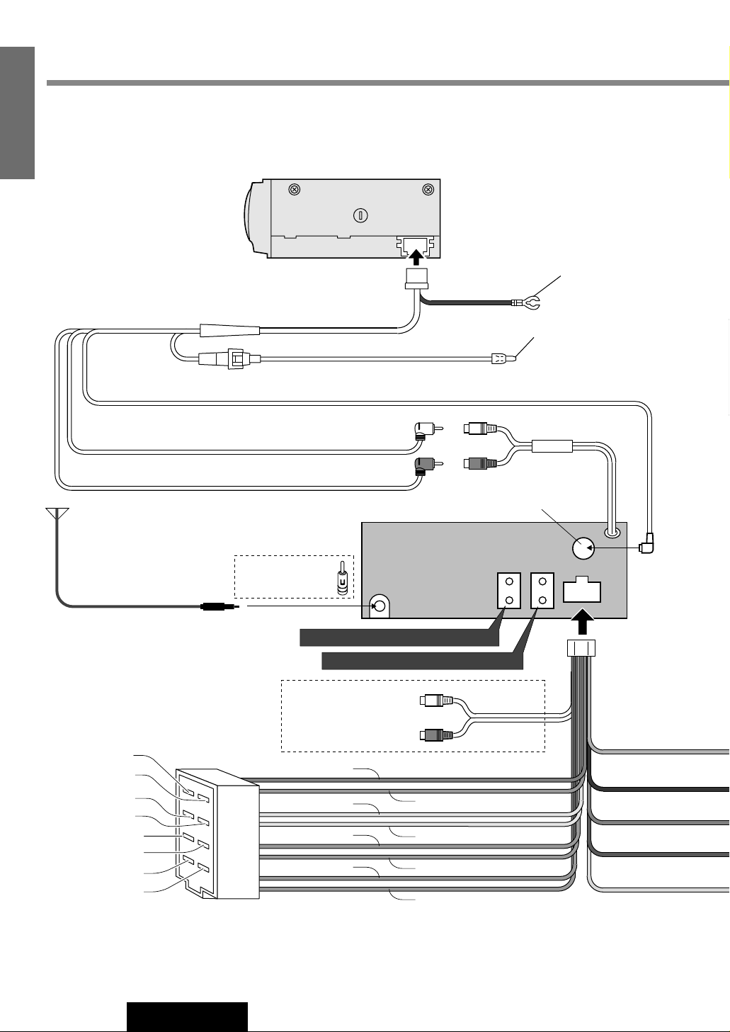
Cable Wiring Diagram
Example : Connection with CD changer CX-DP88N (Option).
Electrical Connections
Page 25
(Yellow)
(Red)
(Black)
(Orange)
A (Black)
(Dark blue)
(Dark blue)
Resistor(1kΩ)
<For CQ-FX321N>
BATTERY 15A
ACC
A5
Fuse(15A)
RCA Cord
of CD changer
ePower
Connector
R(Red)
L(White)
(L)(White)
(R)(Red)
CD Changer
Control
Connector
Preamp Out
Connector (Rear)
CD Changer
Input Connector
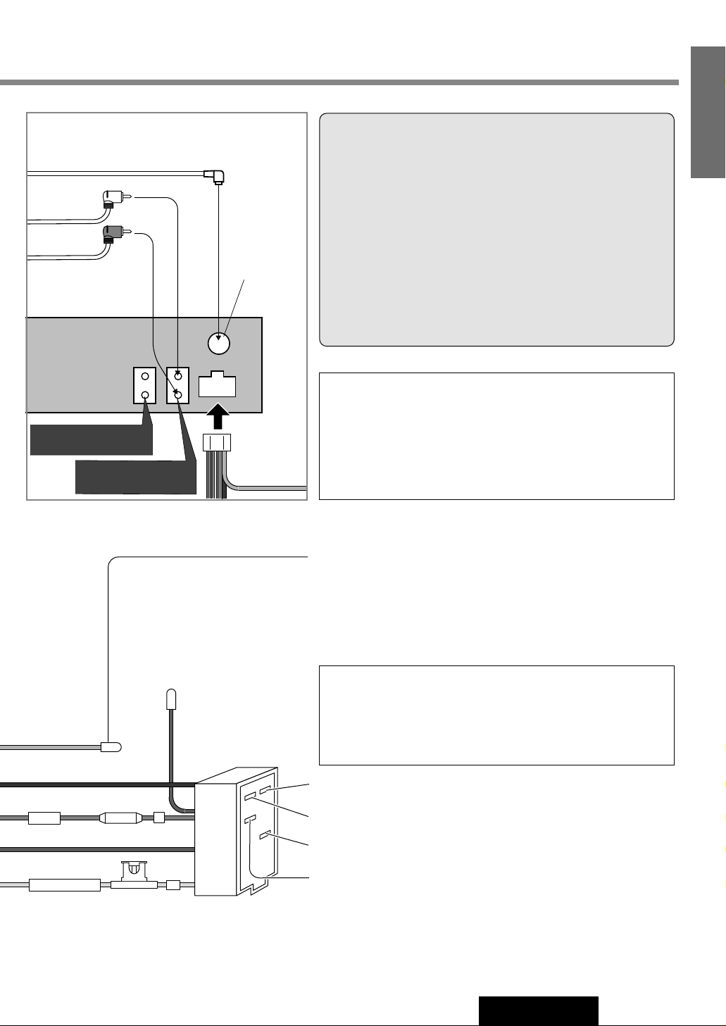
* Telephone Mute
The sound from the speakers cannot be heard while the telephone conversation is in progress.
** Navi Mute
The sound from the speakers cannot be heard while the navigation guide is on.
Cautions:
¡Check the connectors provided on your car (see note on page
4 and 5) before connecting the system.
¡This unit is designed for use in a car having a 12-volt negative
ground battery system.
¡To prevent damage to the unit, be sure to follow the connection
diagram below.
¡Strip about 5 mm of the lead ends for connection (only non-
ISO connector cords).
¡Do not insert the power connector into the unit until the wiring
is completed.
¡Be sure to insulate any exposed wires to prevent short circuit-
ing with the car chassis. Bundle all cables, and prevent cable
terminals from touching any metal parts.
¡This unit can be connected to an optional CD changer (CX-
DP9061/DP9060EN, CX-DP88N, CX-DP801/DP803EN or CXDP601EN) and optional extension cord.
¡For details consult your nearest authorized Panasonic Dealer.
¡For connection to a CD changer, refer to the operating instruc-
tions of the CD changer (CX-DP9061/DP9060EN, CX-DP88N,
CX-DP801/803EN or CX-DP601EN).
C1 : (Orange)
Telephone Mute Lead (*)
Connect to the car telephone mute lead.
Note: The telephone mute lead is only for connection to the radio
mute lead. Output other than telephone will not be muted
Navi Mute Lead (**)
To the Navi Mute lead of the Panasonic car navigation system.
A8 : Ground Lead (Black)
To a clean, bare metallic part of the car chassis
A7 : Power Lead (ACC or IGN) (Red)
To ACC power, +12VDC
A4 : Battery Lead (Yellow)
To the car battery, continuous +12 V DC
A5 : (Dark blue)
Motor Antenna Relay Control Lead
(To Motor Antenna) (Max. 500mA)
This lead is not intended for use with a switch actuated power antenna.
Amp·Relay Control Power Lead
This lead is for connection to a Panasonic power amplifier.
25
CQ-FX421/FX321N
20
E
N
G
L
I
S
H
Page 26
26
CQ-FX421/FX321N
21
E
N
G
L
I
S
H
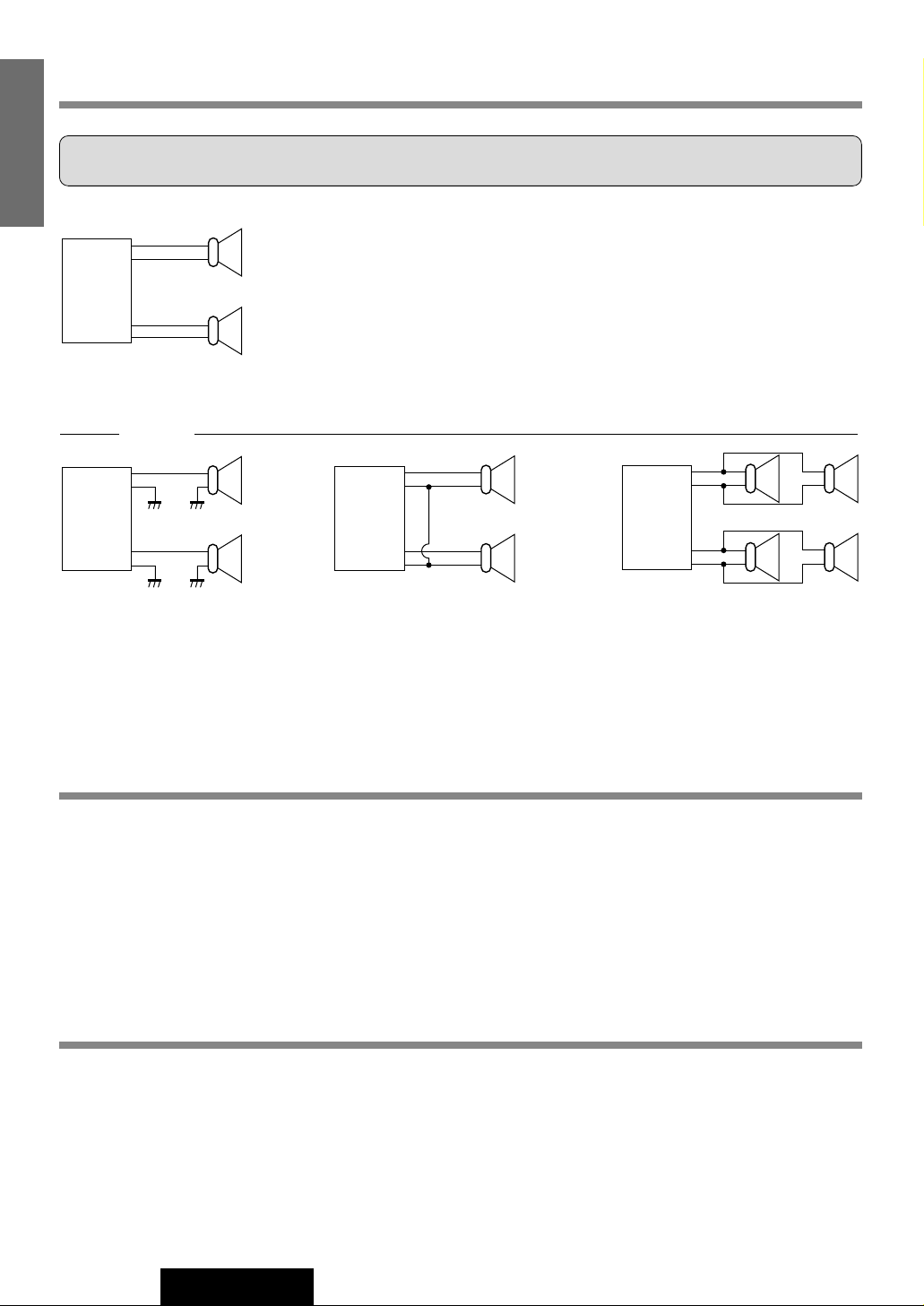
Speaker Connections
Caution: Please follow the instructions given below. Failure to do so will cause damage to the unit and speakers.
Fuse
Use fuses of the same specified rating (15 A). Using different substitutes or fuses with higher ratings, or connecting the unit
directly without a fuse, could cause fire or damage to the unit.
If the fuse replacement fails, contact your nearest authorized Panasonic Service Center.
Maintenance
Your product is designed and manufactured to ensure the minimum of maintenance. Use a soft cloth for routine exterior
cleaning. Never use benzine, thinner, or other solvents.
L
R
-
-
-
-
-
-
-
-
-
-
+
+
+
+
+
+
+
+
+
+
-
+
-
+
-
+
-
+
-
+
-
+
-
+
-
+
L
R
L
R
L
R
<Right>
<Wrong>
(White)
(White
w/black stripe)
Chassis
(Gray
w/black stripe)
(Gray)
Chassis
¡Use ungrounded speaker only.
¡The maximum speaker output should be 45 W or more. (If used with
the optional power amplifier, the speaker output should be higher than
the maximum amplifier output.)
¡The speaker impedance should be 4 - 8 Ω.
¡This unit uses the BTCL circuit, so each speaker should be connected
separately using parallel vinyl insulated cords.
¡The speaker cords and the power amplifier unit should be kept away
(about 30 cm apart) from the antenna and antenna extension cord.
¡Never connect the speaker cord to
the body of the car.
¡Do not use a 3-wire type speaker
system having a common earth
lead.
¡Do not connect more than one
speaker to one set of speaker
leads.
Page 27
27
CQ-FX421/FX321N
22
E
N
G
L
I
S
H
General
FM Stereo Radio
Specifications
Frequency Range : 87.5 - 108 MHz
Usable Sensitivity : 6 dB/µV(S/N 30 dB)
Stereo Separation : 35 dB (at 1 kHz)
Frequency Range : 531 - 1,602 kHz
Usable Sensitivity : 28 dB/µV (S/N 20 dB)
Frequency Range : 153 - 279 kHz
Usable Sensitivity : 32 dB/µV (S/N 20 dB)
Reproduction System : 4-track, 2-program stereo
Tape Speed : 4.76 cm/sec.
FF/REW Time : Less than 110 sec. (C-60)
Frequency Response : 30 - 17,000 Hz (normal)
30 - 18,000 Hz (metal)
Wow and Flutter : 0.12 % (WRMS)
Signal to Noise Ratio : 52 dB
(Dolby off)
62 dB (Dolby B NR on)
Cassette Tape Player
LW Radio
MW Radio
Power Supply : DC 12 V (11 V - 16 V), Test
Voltage 14.4 V, Negative
Ground
Tone Controls : Bass; ±12 dB at 100 Hz
Treble;±12 dB at 10 kHz
Current Consumption : Less than 2.5 A (tape
mode, 0.5 W 4-Speaker)
Maximum Power Output : 45 W x 4 (at 4 Ω)
Power Output : 22 W x 4
(DIN45 324, at 4 Ω)
Speaker Impedance : 4 - 8 Ω
Pre-Amp Output Impedance : 600 Ω
Sub-Woofer Output Voltage :
2 V (CQ-FX421N)
Dimensions (Main Unit) : 178(W) x 50(H) x
150(D) mm
Weight (Main Unit) : 1.6 kg
Note: Specifications and design are subject to modification without notice due to improvements.
Dolby noise reduction manufactured under license from Dolby Laboratories Licensing Corporation.
“DOLBY” and the double-D symbol B are trademarks of Dolby Laboratories Licensing Corporation.
Page 28

P.T. National Gobel
JI.Raya Jakarta-Bogor Km.29 P.O.BOX 6000, Jakarta 13710 INDONESIA
YEFM283652 NAB0201-0 Printed in Indonesia
Matsushita Electric Industrial Co., Ltd.
Central P.O. Box 288, Osaka 542-8588, Japan
 Loading...