

Page 1
ORDER No. 6072
CUSTOM MADE FOR
SUBARU
CQ-EF7160A
AM/FM MPX ELECTRONIC TUNING
RADIO with Stereo Cassette Tape
Player and 6-Disc CD Changer
SUBARU PART No. : 86201SA030
ID CORD : P127
VEHICLE : FORESTER
DESTINATION : North America
PRODUCED AFTER : Jan., 2002
I0
Specification*
General
Power Supply DC 12V (11V - 16V),
Test Voltage 13.2V
Negative Ground
Current Consumption Less than 2.5A (Vol. Max.)
Maximum Power Output 25W×4ch
Output Impedance 4Ω
AM Radio
Frequency Range 530 - 1,710kHz
Usable Sensitivity 26dB/µV (S/N 20dB)
FM Stereo Radio
Frequency Range 87.7 - 107.9MHz
Usable Sensitivity 6dB/µV (S/N 30dB)
WB Radio
Frequency Range 162.400 - 162.550MHz
Usable Sensitivity 6dB/µV (S/N 20dB)
Cassette Player
Reproduction System 4-Track, 2-Program Stereo
Tape Speed 4.76cm/sec.
Wow and Flutter Less than 0.2% (WRMS)
Signal to Noise Ratio 55dB
CD Changer
Signal to Noise Ratio More than 68dB (IHF-A)
Total Harmonic Distortion Less than 0.4%
Channel Separation 62dB (IHF-A)
Dimensions** (W×H×D) 178×100×174mm
Weight** 2.7kg
* Specifications and the design are subject to possible modification
without notice due to improvements.
** Dimensions and Weight shown are approximate.
Doldy noise reduction manufactured under license from Dolby
Laboratories Licensing Corporation.
“Dolby” and the double-D symbol
Laboratories Licensing Corporation.
are trade marks of Dolby
Page 2

CUSTOM MADE FOR SUBARU / CQ-EF7160A
CONTENTS
Page Page
1 FEATUERS 2
2 LASER PRODUCTS
3 REAR VIEW
4 FRONT VIEW AND FUNCTIONS
5 OPERATION OF CONTROLS
6 WIRING CONNECTION
7 BLOCK DIAGRAM (Main Block)
8 BLOCK DIAGRAM (CD Servo Block)
9 TERMINALS DESCRIPTION
10 ALIGNMENT INSTRUCTIONS
11 ALIGNMENT POINTS
12 CD DISC CENTERING ALIGNMENT
13 PACKAGE AND IC BLOCK DIAGRAM 14
2
14 REPLACEMENT PARTS LIST
2
15 EXPLOD ED VIEW (Unit)
3
16 CD CHANGER PARTS LIST
4
17 EXPLOD ED VIEW (CD Deck-1)
6
18 EXPLOD ED VIEW (CD Deck-2)
7
19 EXPLOD ED VIEW (CD Deck-3)
8
20 TAPE PLAYER PARTS
9
21 EXPLOD ED VIEW (Tape Deck)
12
22 WIRING DIAGRAM
12
23 SCHEMATIC DIAGRAM-1
13
24 SCHEMATIC DIAGRAM-2
17
21
22
25
26
27
28
29
30
37
39
1 FEATUERS
·
18-station preset (12-FM, 6-AM)
·
Scan Tuning.
·
TPS function.
·
Dolby noise reduction.
·
6-disc CD changer (in dash board).
·
CD changer control.
·
Electronic sound control function.
2 LASER PRODUCTS
3 REAR VIEW
2
Page 3
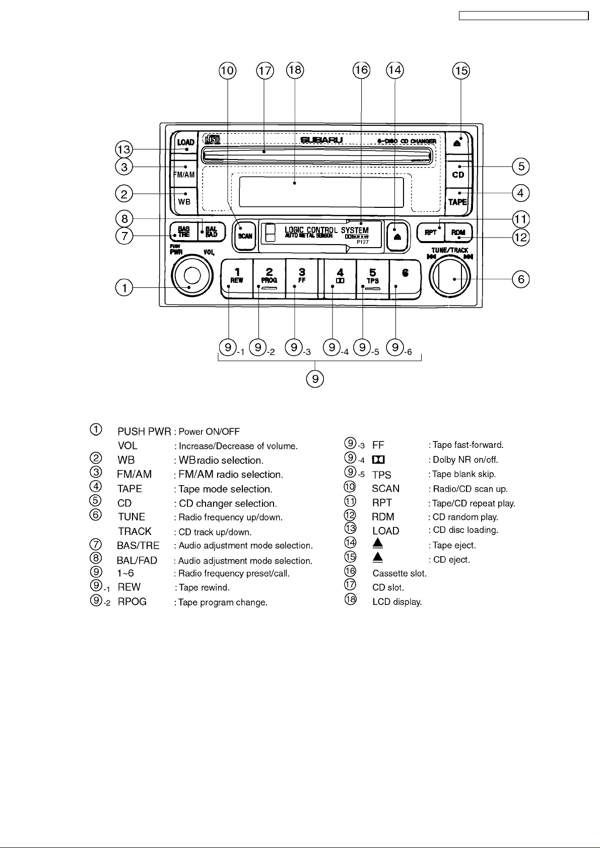
4 FRONT VIEW AND FUNCTIONS
CUSTOM MADE FOR SUBARU / CQ-EF7160A
3
Page 4
CUSTOM MADE FOR SUBARU / CQ-EF7160A
5 OPERATION OF CONTROLS
5.1. Power and Volume Controls
5.1.1. Power
·
Press PWR knob (1) to switch on the power.
·
Perss PWR knob (1) again to switch off the power.
5.1.2. Volume
·
Turn VOL knob (1) to the right or left to increase or
decrease the volume.
5.2. Tone Controls
5.2.1. Changing Audio Modes
·
Press BAS/TRE button (7) to change the audio mode as
follows.
BASS → TREB → VOL → .... BASS ...
5.2.2. Bass
1. Press BAS/TRE button (7) to select the bass mode.
2. Turn knob (1) to the right or left to increase or decrease the
low tones.
5.2.3. Treble
1. Press BAS/TRE button (7) to select the treble mode.
2. Turn knob (1) to the right or left to increase or decrease the
high tones.
5.4. Radio Controls
5.4.1. Selecting a Band
·
Press FM/AM button (3) to select the FM/AM band.
FM → AM → ... FM ...
5.4.2. Manual Tuning
·
Turn TUNE knob (6) to the right less than 0.5 seconds to
move to a higher frequency by one step.
·
Turn TUNE knob (6) to the left less than 0.5 seconds to
move to a lower frequency by one step.
AM FM
One Step 10kHz 0.2MHz
·
Turn TUNE knob (6) to the right or left more than 0.5
seconds to move to a higher or lower frequency
continuously.
5.4.3. Scan Tuning
·
Pess SCAN button (10). The frequency becomes
continuously higher by one step.
·
When receiving a station, scanning operation pauses
automatically for approx 5 sec, and then start scanning for
next station again.
5.3. Baiance and Fader Controls
5.3.1. Changing Audio Modes
·
Press BAL/FAD button (8) to change the audio mode as
follows.
BAL → FAD → VOL → .... BAL ...
5.3.2. Balance
1. Press BAL/FAD button (8) to select the balance mode.
2. Turn knob (1) to the right or left to shift the sound volume to
the right or left speakers.
5.3.3. Fader
1. Press BAL/FAD button (8) to select the fader mode.
2. Turn knob (1) to the right or left to shift the sound volume to
the front or rear speakers.
4
Page 5
5.5. Tape Controls
5.5.1. Selecting a Tape Mode
·
Press TAPE button (4) , if a cassette is loaded, then the
mode changes to the tape player mode.
5.5.2. Fast Forward and Rewind
·
Press FF button (9)-3 to fast forward the tape.
·
Press REW button (9)-1 to rewind the tape.
5.5.3. Changing Sides
·
Press PROG button (9)-2 to change to the program on the
other side of the tape.
5.5.4. TPS Mode
·
Press TPS button (9)-5 to skip long unrecorded portions
more than 15 secondes on the tape.
5.5.5. TPS FF and REW
·
If FF button (9)-3 press within TPS mode, the cassette
player fast forward to the beginning of the next music.
·
If REW button (9)-1 press within TPS mode, the cassette
player rewind to the beginning of the current music.
CUSTOM MADE FOR SUBARU / CQ-EF7160A
play from the beginning of the track.
5.6.6. Fast Forward and Revers
·
Turn knob (6) to the right more than 0.5 seconds to fast
forward a track.
·
Turn knob (6) to the left more than 0.5 seconds to reverse
through a track.
5.6.7. Repeating a Track
·
Press RPT button (11) to repeat the current selection.
5.6.8. Random Selection
·
Press RDM button (12). A random selection of music is
played from all available tracks on the current disc.
5.5.6. Repeat Play
·
Press RPT button (11) to repeat the same music.
5.5.7. Dolby Noise Reduction
·
Press "Dolby" button (9)-4 to set the Dolby B NR mode.
5.6. CD Changer Controls
5.6.1. Selecting a CD Changer
·
Press CD button (5) to change the CD changer as follows.
→ 6-disc CD CH (in dash board) → 6-disc CD CH (for BUS I/F) →
5.6.2. Loading Discs <Only for “in Dash
Board Changer”>
·
Press LOAD button (13) less than 1.5 secondes to load a
disc.
·
Press LOAD button (13) more than 1.5 secondes to load all
the disc.
5.6.3. Ejecting Discs <Only for “in Dash
Board Changer”>
......
·
Press button (15) less than 1.5 secondes to eject a playing
disc.
5.6.4. Selecting a Disc
·
Press one of the bottons (9) to select a dsired disc.
5.6.5. Selecting a Track
·
Turn TRACK knob (6) to the right less than 0.5 secondes to
go to the next track.
·
Turn TRACK knob (6) to the left less than 0.5 seconds to
5
Page 6
CUSTOM MADE FOR SUBARU / CQ-EF7160A
6 WIRING CONNECTION
6
Page 7
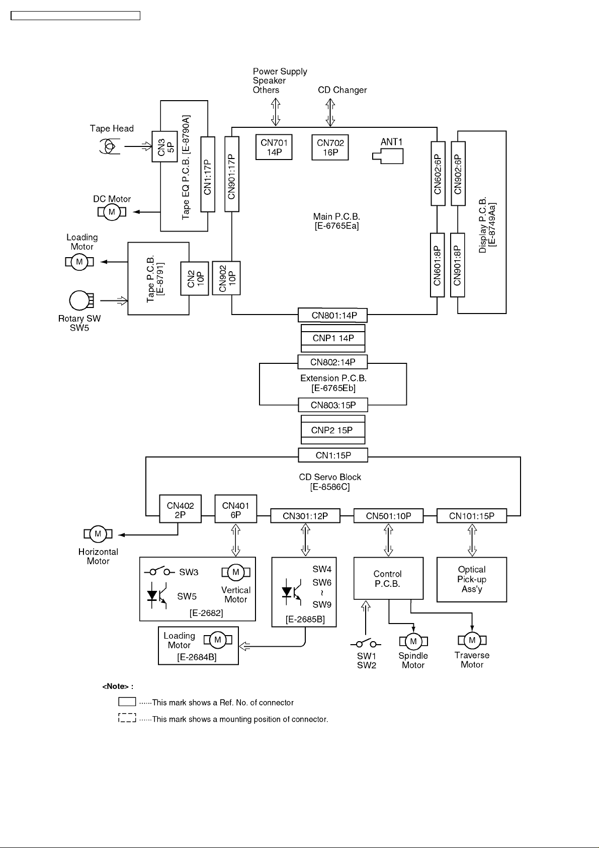
7 BLOCK DIAGRAM (Main Block)
CUSTOM MADE FOR SUBARU / CQ-EF7160A
7
Page 8
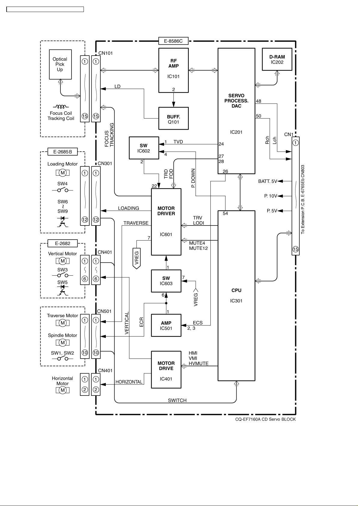
CUSTOM MADE FOR SUBARU / CQ-EF7160A
8 BLOCK DIAGRAM (CD Servo Block)
8
Page 9
9 TERMINALS DESCRIPTION
CUSTOM MADE FOR SUBARU / CQ-EF7160A
9.1. Main Block
IC601 : C2BBGF000299
Pin
No.
1 BATT-DET Batterylevel detection I 4.7
2 ACC-DET ACC level detection I 4.7
3 WB.CONT (Ground pull-down) - 0
4 FM.CONT FM radio power control O 5.1
5 AM/FM.CONTRadio power control O 5.0
6 CD-ON CD controll enable O 5.4
7 CD-RESET CD reset O 5.3
8 CD-SOM CD serial data O 4.9
9 CD-SIM CD serial data I 5.2
10 CD-SCKM Shift clock for CD serial data O 5.3
11 CD-SW1 (Ground pull-down) I 0
12 CD-SW3 (Ground pull-down) I 0
13 IDC.CONT CD changer power control O 5.2
14 DOLBY Dolby NR control O 0
15 M1-A Tape main motor control O 0
16 M1-B Tape main motor control O 0
17 END-A Tape end detection I 1.5
18 END-B Tape end derection I 1.6
19 VOL.CLK Electronic volume clock O 0
20 VOT.DATA Electronic volume data O 0
21 MUTE System mute O 0
22 AMP.C Power Amp. stand-by O 5.2
23 V.CONT (Ground pull-down) - 0
24 ILL.C (Ground pull-down) - 0
25 EQ/AM.IN (Ground pull-down) - 0
26 BIT1 Tape mode switch I 4.9
27 AVDD +5V power supply - 5.2
28 BIT2 Tape mode switch I 4.9
29 BIT3 Tape mode switch I 0
30 SD B/S detection I 0
31 FM.ST FM stereo detection I 0.4
32 AVSS Ground - 0
33 REGCPU Coupling capacitor terminal - 3.4
34 VDD +5V power supply - 5.2
35 REGOSC Coupling capacitor terminal - 5.2
36 X2 Crystal oscillator - 2.2
37 X1 Crystal oscillator - 0
38 GND Ground - 0
39 SSC Serch stop clear O 0
40 GND Ground - 0
41 AM.IF AM IF counter O 0
42 FM.IF FM IF counter O 0
43 PLL.VDD PLL +5V power supply - 5.2
44 FM.OSC FM local OSC I 2.4
45 AM.OSC AM local OSC I 1.3
46 PLL.GND Ground - 0
47 EO0 PLL phase error O 1.4
48 NC No connection - 49 IC (Connecting to ground) - 0
50 /RESET System reset I 4.8
51 CD.EJ CD eject switch I 5.1
52 TAPE.EJ Tape eject switch I 5.1
53-57 KI1-5 Key data input I 0
58 AM NC (Ground pull-down) - 0
59 BEEP Beep output O 0
60 DIV ON/OFF (+5V pull-up) - 5.0
61-66 - Not used - -
67 M2 Tape sub motor control O 0
68 M2F Tape sub motor control O 0.5
Port Description I/O (V)
69 EN-B Rotary encoder data I 0
70 EN-A Rotary encoder data I 0
71 SYIYOU6 Specification setting I 4.9
72 SYIYOU7 Specification setting I 0
73 SYIYOU8 Specification setting I 0
74 LCD.DIN LCD data O 5.1
75 LCD.CE LCD chip enable O 0
76 LCD.CLK LCD shift clock O 0
77 LCD.DOUT LCD data I 0
78 POWER.SW Power switch input I 5.1
79 CD-CH.IN CD changer data I 5.1
80 CD-CH.OUT CD changer data O 0
81 ILL.DET (ACC5V pull-up) I 5.1
82 GND Ground - 0
83 TEST.P Test point I 5.1
84 SYIYOU1 Specification setting I 5.0
85 SYIYOU2 Specification setting I 0
86 SYIYOU3 Specification setting I 0
87 SYIYOU4 Specification setting I 5.0
88 SYIYOU5 Specification setting I 0
89 P.CONT Power control O 5.1
90 LCD.C LCD illumi. control O 5.1
91 TAPE.CONT Tape power control O 4.6
92 A/B.OUT Tape FF/REW selection O 0
93 MS-PL/FF MS mode control O 0
94 MSM MS gain control O 0
95 MS Tape unrecorded portion detection I 0
96 A/B.IN Tape side detection I 0
97 T.LOAD Tape loading detection I 0
98 T-IN Tape-in signal I 0
99 VDD +5V power supply - 5.2
100 GND Ground - 0
Note :
Voltage measuerments are with respect to ground, with a
voltmeter (Internal resistance : 10M ohms.)
9.2. Display Block
IC901 : YEAMLC75853
Pin
No.
1-15 S1-S15 LCD segment data O 2.5
16-19 S16-S19 Not used - 20-40 S20-S40 LCD segment data O 2.5
41-43 COM1-3 LCD common O 2.5
44-47 KS1-4 Key scan O 0.9
48,49 KS5, 6 Not used - 50-54 KI1-5 Key data I 0
55 TEST (Connecting to ground) - 0
56 VDD +5V power supply - 5.1
57 VDD1 Ground through capacitor terminal - 3.3
58 VDD2 Ground through capacitor terminal - 1.7
56 Vss Ground - 0
60 OSC CR oscillator terminal - 3.9
61 DO LCD data O 4.4
62 CE LCD driver chip enable I 0
63 CL Clock for LCD I 0
64 DI LCD data I 0
Port Description I/O (V)
9
Page 10
CUSTOM MADE FOR SUBARU / CQ-EF7160A
9.3. CD Servo Block
IC201 : MN662783RPW
Pin
No.
1 VDD +5V power supply - 5.0
2 D0 D-RAM data I/O 2.3
3 D1 D-RAM data I/O 1.8
4 /WE D-RAM data write O 4.9
5 /RAS D-RAM row address strobe O 3.4
6 D2 D-RAM data I/O 0.8
7 D3 D-RAM data I/O 0
8 /CAS0 D-RAM columun address strobe O 3.9
9 /CAS1 D-RAM columun address strobe O 0
10 A8 D-RAM address O 0.6
11 A7 D-RAM address O 1.1
12 A6 D-RAM address O 0.7
13 A5 D-RAM address O 0
14 A4 D-RAM address O 1.1
15 A9 D-RAM address OZ 0.4
16-18 A0 D-RAM address O 1.0
19 A3 D-RAM address O 0
20 VSS2 Ground - 0
21 VDD2 +5V power supply - 5.0
22,23 - Not used - -
24 TVD Traverse motor control O 2.5
25 PC Not used - 26 ECS Spindle motor control O 2.4
27 TRD Tracking coil drive O 2.5
28 FOD Focus coil drive O 2.4
29 FBAL Focus balance O 1.9
30 TBAL Tracking balance O 3.0
31 VREF Refence voltage I 2.5
32 FE Focus error I 2.5
33 TE Tracking error I 2.5
34 RFENV RF envelope I 2.5
35 OFT Off track signal I 0
36 /RFDET RF detecting signal I 0
37 BDO Drop-out signal I 0
38 LDON Laser on signal O 4.5
39 ARF RF signal I 2.5
40 IREF Reference current input I 1.2
41 DRF Bias for DSL I 2.4
42 DSLF Loop filter for DSL I/O 2.5
43 DSLF2 Loop filter for DSL I/O 2.2
44 PLLF Loop filter for PLL I/O 1.4
45 VCOF Not used - 46 AVDD2 +5V power supply - 5.0
47 AVSS2 Ground - 0
48 OUTL L channel output O 2.3
49 AVSS1 Ground - 0
50 OUTR R channel output O 2.3
51 AVDD1 +5V power supply - 4.7
52-54 - (Connecting to ground) - 0
55 FLAG Flag output O 0
56 FCLK Frame clock O 0
57-59 - Not used - -
60 TX Not used - 61 MCLK Clock for I/F command I 1.0
62 MDATA Date for I/F command I 3.1
63 MLD I/F command load I 5.0
64 BLKCK Subcode block clock O 0
65 SQCK Ext.clock for sub code-Q I 5.0
66 SUBQ Code for sub. code-Q O 3.8
67 DMUTE Mute input I 0
68 STAT Status signal O 5.0
69 /RST Reset input I 5.0
Port Description I/O (V)
70 CSEL (Connecting to ground) - 0
71 PMCK Clock output O 2.5
72 SMCK Clock output O 2.5
73 SUBC Serial data of sub code O 0
74 SBCK Shift clock for SUBC I 0.6
75 /CLDCK Not used - 76 /TEST (Connecting to VDD) - 5.0
77 X1 Crystal oscillator - 0.4
78 X2 Crystal oscillator - 3.2
79 VDD1 +5V power supply - 5.0
80 VSS1 Ground - 0
IC301 : MN1873260AB
Pin
No.
1 VDD +5V power supply - 5.0
2 OSC2 Crystal oscillator - 2.2
3 OSC1 Crystal oscillator - 2.1
4 VSS Ground - 0
5 XI (Connecting to ground) - 0
6 XO Not used - 7 CM (Connecting to ground) - 0
8 VREFH Reference voltage I 5.0
9 SW13 Shuter SW I 4.9
10 SW12 Horizontal origin I 4.9
11 SW11 Clump SW I 0
12 SW10 Play SW I 0
13 SW4 Shuter SW I 4.9
14 SW3 Tray origin SW I 0
15 SW2 Inner SW I 4.8
16 SW1 Outer SW I 4.9
17 VREFL Reference voltage I 0
18 /RESET Reset input I 4.9
19 - (Ground pull-down) - 0
20 SCKM Clock for serial data I 5.0
21 SIM CD changer serial data I 1.3
22 SOM CD changer serial data O 4.3
23 SQCK Ext. clock for sub. code-Q O 5.0
24 SUBQ Code for sub. code-Q I 1.6
25 - Not used - 5.0
26 - (Ground pull-down) - 0
27 CD.ON CD changer start/stop I 5.0
28 - Not used - 5.0
29 BLKCK Sub. code block clock I 0
30 P.ON Not used - 5.0
31 MUTE Mute output O 5.0
32 - (Ground pull-down) - 0
33 SENS Servo status O 0
34 CLVS Servo status O 5.0
35 FLOCK Focus servo lock O 0.2
36 TLOCK Tracking servo lock O 0
37 VMI Horizontal motor control O 2.5
38 HMI Vertical motor control O 0
39 HVMUTE H/V motor mute O 0
40-42 - (Ground pull-down) - 0
43 SW9 Disc-in (B) SW I 0
44 SW8 Disc-in (L) SW I 0
45 SW7 Disc-in (F) SW I 0
46 SW6 Disc push SW I 0
47 SW5 Tray hight SW I 4.5
48 BDO Drop-out signal I 0
49 DQSY Not used - 50 /RST Reset output O 5.0
51 STAT Status signal I 2.1
52 DMUTE Mute output O 0
53 XE Not used - -
Port Description I/O (V)
10
Page 11
54 P.DOWN Power down signal O 0
55 - No connection - 56 MLD I/F command load O 5.0
57 MDATA Data for I/F command O 3.1
58 MCLK Clock for I/F command O 4.1
59 SPMT Spindle mute O 5.0
60 MUTE12 Focus/Tracking mute O 0
61 MUTE4 Loading motor mute O 4.8
62 LDOI Loading motor control I/O 2.5
63 TRV Forced traverse control I/O 2.4
64 SYNC Not used - -
CUSTOM MADE FOR SUBARU / CQ-EF7160A
11
Page 12
CUSTOM MADE FOR SUBARU / CQ-EF7160A
10 ALIGNMENT INSTRUCTIONS
10.1. Alignment Conditions
·
Power Supply Voltage : DC13.2V
·
Output Impedance : 4
·
Output Power : 0.5W
Note :
Do not align the FM/AM package block. When the package block is necessary, it will be supplied already aligned at the
factory.
Ω
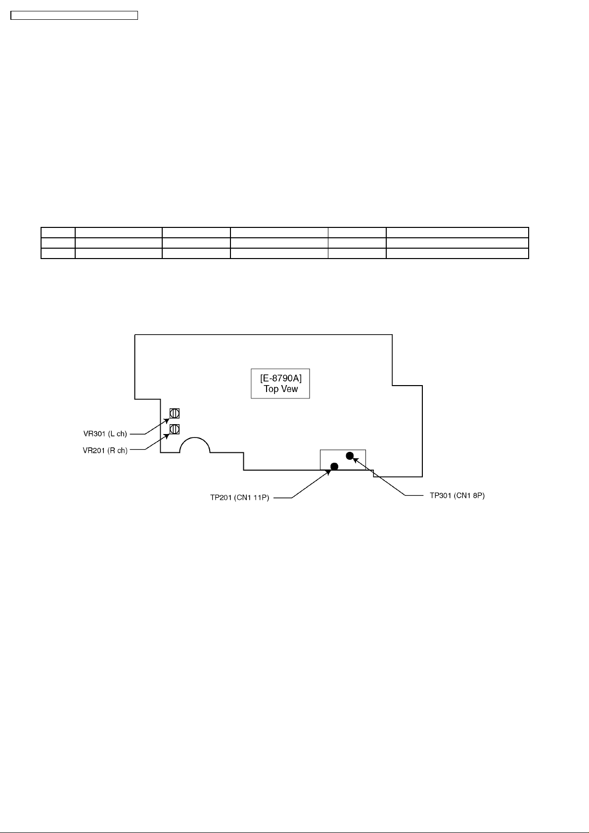
10.2. Dolby NR Alignment
Step Alignment Item Test Tape VTVM Connection Adjust Remarks
(1) DOLBY NR Rch RFKZ0038 TP201 VR201 Adjust for 388mV ±1.0dB
(2) DOLBY NR Lch RFKZ0038 TP301 VR301 Adjust for 388mV ±1.0dB
11 ALIGNMENT POINTS
·
Balance, Fader Control : center
·
Bass, Treble Control : Center
·
Dolby NR: OFF
12
Page 13

CUSTOM MADE FOR SUBARU / CQ-EF7160A
12 CD DISC CENTERING ALIGNMENT
·
This adjustment is for assuring that compact discs will be placed in the center of the turntable.
<Adjustment Condition / Jig>
·
Power Supply Voltage : 13.2V
·
Test Disc : TCD-784M
<Adjustment Procedures>
1. Attach the adjusting screw to the upper chassis (See Figure 1.).
2. Insert the test CD (TCD-784M) into the disc No.1 position and play it.
3. After checking whether the disc is centered on the turntable, turn the adjusting screw unit it is in the center.
<Check Items>
·
Check that the disc is correctly centered.
·
Check that the disc is securely clamped.
·
Check that no abnormal noise is produced when clamping the disc.
[Directions of Turning the Adjusting Screw]
·
CD stops before its proper position : Turn the screw counterclockwise.
·
CD overruns : Turn the screw clockwise.
4. After the adjustment, lock the screw.
13
Page 14

CUSTOM MADE FOR SUBARU / CQ-EF7160A
13 PACKAGE AND IC BLOCK DIAGRAM
13.1. Main Block
PA101 : YEP0PTA514B0
IC201 : C1BB000 00284
IC301 : C1BA000 00201
14
Page 15

CUSTOM MADE FOR SUBARU / CQ-EF7160A
IC701 : YEAMA61W12ST
IC702 : YEAMLB1930MT
13.3. CD Servo Block
IC741 : AN8065SE1
13.2. Tape Block
IC1 : YEAMCX1980QK
IC101 : YEAMBA6354BF
15
Page 16

CUSTOM MADE FOR SUBARU / CQ-EF7160A
IC202 : C3ABMB000010
IC601 : YEAMBA5971FP
IC401 : YEAMBA6792FY
IC501 : YEAMPC358G2T
IC603 : YEAMT4W53FUL
16
Page 17

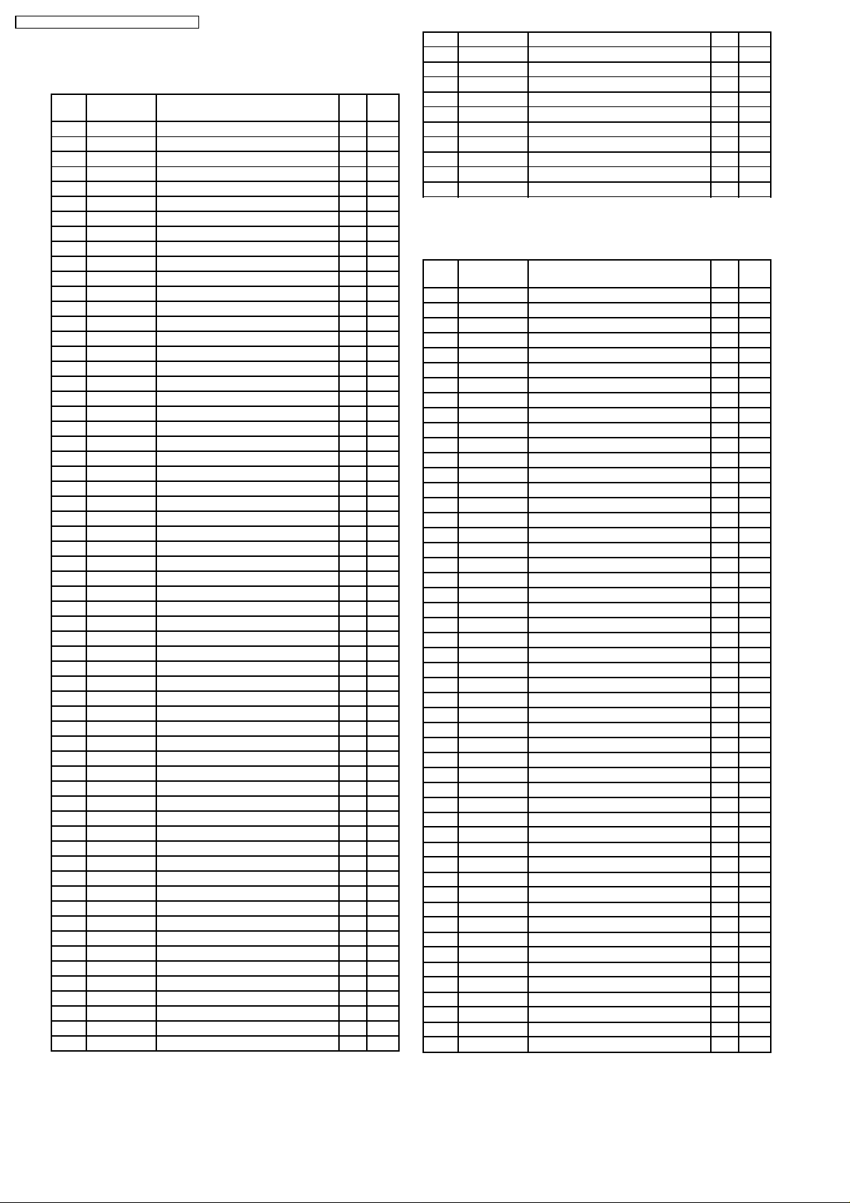
14 REPLACEMENT PARTS
LIST
Notes :
1. Be sure to make your orders of replacement parts
according to this list.
2. Important safety notice: Components, identified by
have special characteristics important for safety. When
replacing any of these components, use only
manufacturer´s specified parts.
3. Location keys in the remarks column indicates the general
location of the parts shown in the exploded drawing, as in a
road map.
4. The marking (RTL) indicates that Retention Time is limited
for this item. After the discontinuation of assembly in
production, the item will continue to be available for a
specific period of time. The retention period of availability is
dependent on the type of assembly, and in accordance with
the laws governing part and product retention. After the end
of this period, the assembly will no longer be available.
5. "MCC" marks in remarks column are indicated supply parts
of Matsushita Communication Industrial Corp. of America
(MCC).
Ref.
No.
[E6765E] Main Block
IC´s and TRANSISTORs
IC181 YEAMPC4570T1 IC
IC201 C1BB00000284 IC
IC301 C1BA00000201 IC
IC372 C0ABAB000001 IC
IC601 C2BBGF000299 IC
IC701 YEAMA61W12ST IC
IC702 YEAMLB1930MT IC
IC741 AN8065SE1 IC
PA101 YEP0PTA514B0 Electronic Tuner
PA181 YEAU034CSU02 Electronic Tuner
Q241 B1GBCFNN0004 Transistor
Q280 YEANFMG12T Transistor
Q451 YEAN2SK536TB Transistor
Q701 B1BBAC000007 Transistor
Q702 YEAND1862T Transistor
Q703 2SB1398QTA Transistor
Q704 2SB1073TX Transistor
Q705 YEANC114YKX Transistor
Q706 YEANBP1F3PT Transistor
Q707 YEANC114YKX Transistor
Q710 YEANBP1F3PT Transistor
Q711 YEANC114YKX Transistor
Q712 YEAN2SD1856 Transistor
Q721 YEANBP1F3PT Transistor
Q722 YEANC114YKX Transistor
Q723 YEANBP1F3PT Transistor
Q724 YEANC114YKX Transistor
Q725 YEANBP1F3PT Transistor
Q726 YEANC114YKX Transistor
Q731 YEANC114YKX Transistor
Q732 YEANC114YKX Transistor
Q733 B1GDCFJN0004 Transistor
Q740 B1ACJJ000001 Transistor
Q741 YEANC114YKX Transistor
Q742 B1GDCFNN0002 Transistor
Q754 YEANC114YKX Transistor
Q755 YEAN2SD1856 Transistor
Q756 YEANC114WKTX Transistor
Q770 YEANBP1F3PT Transistor
Q771 YEAN2SD1856 Transistor
Q772 YEANC114YKX Transistor
Part No. Part Name & Description Remarks
mark
CUSTOM MADE FOR SUBARU / CQ-EF7160A
Ref.
No.
Q773 YEANC114WKTX Transistor
Q801 B1ABCF000044 Transistor
Q802 YEANC114YKX Transistor
Q803 YEANA1037KTX Transistor
Q901 B1GBCFNN0004 Transistor
DIODEs
D101 MA856TA Diode
D102 MA3X152A0L Diode
D151 MA152WKTX Diode
D181 MA856TA Diode
D231 B0ACCK000005 Diode
D232 MA3X152K0L Diode
D233 B0ACCK000005 Diode
D601 MA152WATX Diode
D701 YEADZSA5A27F Diode
D702 YEADRB051L40 Diode
D705 YEADRD91M2T1 Diode
D706 YEADRD56M3T1 Diode
D707 YEADSR1544TL Diode
D708 MA152WKTX Diode
D720 B0BC9R600001 Diode
D756 B0ACCK000005 Diode
D757 MAZ40820MF Diode
D770 B0ACCK000005 Diode
D771 MAZ40820MF Diode
D772 MA165TA Diode
D801 MA153TX Diode
D901 YEADEC10DS1 Diode
D902 MA152WATX Diode
CAPACITORs
C51 YECUS1H102KX Ceramic, 1000PF 50WV
C52 YECUS1H103KX Ceramic, 0.01µF 50WV
C53 YECUS1H471JM Ceramic, 470PF 50WV
C101 YECUS1C154KX Ceramic, 0.15µF 16WV
C102 YECUS1H472KX Ceramic, 4700PF 50WV
C103 YECUS1H103KX Ceramic, 0.01µF 50WV
C104 YECUS1E393KX Ceramic, 0.039µF 25WV
C121 YECUS1E273KX Ceramic, 0.027µF 25WV
C124 YECUS1H682KX Ceramic, 6800PF 50WV
C125 YECUS1C474KX Ceramic, 0.47µF 16WV
C131 YECUS1E273KX Ceramic, 0.027µF 25WV
C134 YECUS1H682KX Ceramic, 6800PF 50WV
C135 YECUS1C474KX Ceramic, 0.47µF 16WV
C151 ECA1CM100I Electrolytic, 10µF 16WV
C152 YECUS1H151JM Ceramic, 150PF 50WV
C153 YECUS1H471JM Ceramic, 470PF 50WV
C154 YECUS1E223KX Ceramic, 0.022µF 25WV
C156 YECUS1H103KX Ceramic, 0.01µF 50WV
C161 YECUS1E223KX Ceramic, 0.022µF 25WV
C162 ECA1AM221I Electrolytic, 220µF 10WV
C163 YECUS1H103KX Ceramic, 0.01µF 50WV
C164 YECUS1E223KX Ceramic, 0.022µF 25WV
C165 ECA1AM221I Electrolytic, 220µF 10WV
C181 ECA1AM221I Electrolytic, 220µF 10WV
C182 YECUS1E223KX Ceramic, 0.022µF 25WV
C183 YECUS1H101JM Ceramic, 100PF 50WV
C184 YECUS1H392KX Ceramic, 3900PF 50WV
C185 YECUS1C154KX Ceramic, 0.15µF 16WV
C186 YECUS1C154KX Ceramic, 0.15µF 16WV
C187 YECUS1H103KX Ceramic, 0.01µF 50WV
C188 YECUS1H473KX Ceramic, 0.047µF 50WV
C189 YECUS1H473KX Ceramic, 0.047µF 50WV
C191 ECEA0JKS101I Electrolytic, 100µF 6.3WV
C192 YECUS1H103KX Ceramic, 0.01µF 50WV
C200 YECUS1E393KX Ceramic, 0.039µF 25WV
C201 YECUS1C224KX Ceramic, 0.22µF 16WV
C202 YECUS1C104KX Ceramic, 0.1µF 16WV
C203 YECUS1C104KX Ceramic, 0.1µF 16WV
C204 YECUS1H682KX Ceramic, 6800PF 50WV
Part No. Part Name & Description Remarks
17
Page 18

CUSTOM MADE FOR SUBARU / CQ-EF7160A
Ref.
No.
C205 ECEA1HBD010I Electrolytic, 1µF 50WV
C207 YECUS1H821JM Ceramic, 820PF 50WV
C208 ECEA1HBD010I Electrolytic, 1µF 50WV
C209 YECUS1H222KX Ceramic, 2200PF 50WV
C210 YECUS1H222KX Ceramic, 2200PF 50WV
C211 ECEA1CSN100I Electrolytic, 10µF 16WV
C216 ECEA1CSN4R7I Electrolytic, 4.7µF 16WV
C217 YECUS1H681JM Ceramic, 680PF 50WV
C218 YECUS1H561KX Ceramic, 560PF 50WV
C229 YECUS1C154KX Ceramic, 0.15µF 16WV
C230 YECUS1H183KX Ceramic, 0.018µF 50WV
C241 ECEA1HKA010I Electrolytic, 1µF 50WV
C242 ECEA1EKA4R7I Electrolytic, 4.7µF 25WV
C250 YECUS1H102KX Ceramic, 1000PF 50WV
C251 YECUV1C105KX Ceramic, 1µF 16WV
C252 YECUV1C105KX Ceramic, 1µF 16WV
C253 YECUS1H102KX Ceramic, 1000PF 50WV
C261 ECEA1AKA101I Electrolytic, 100µF 10WV
C262 YECUS1H103KX Ceramic, 0.01µF 50WV
C263 YECUS1H103KX Ceramic, 0.01µF 50WV
C281 ECEA1CSN4R7I Electrolytic, 4.7µF 16WV
C292 YECUS1C104KX Ceramic, 0.1µF 16WV
C301 YECUS1C224KX Ceramic, 0.22µF 16WV
C302 YECUS1C104KX Ceramic, 0.1µF 16WV
C303 YECUS1C104KX Ceramic, 0.1µF 16WV
C304 YECUS1H682KX Ceramic, 6800PF 50WV
C305 ECEA1HBD010I Electrolytic, 1µF 50WV
C307 YECUS1H821JM Ceramic, 820PF 50WV
C308 ECEA1HBD010I Electrolytic, 1µF 50WV
C309 YECUS1H222KX Ceramic, 2200PF 50WV
C310 YECUS1H222KX Ceramic, 2200PF 50WV
C311 ECEA1CSN100I Electrolytic, 10µF 16WV
C316 ECEA1CSN4R7I Electrolytic, 4.7µF 16WV
C317 YECUS1H681JM Ceramic, 680PF 50WV
C318 YECUS1H561KX Ceramic, 560PF 50WV
C329 YECUS1C154KX Ceramic, 0.15µF 16WV
C330 YECUS1H183KX Ceramic, 0.018µF 50WV
C350 YECUS1H102KX Ceramic, 1000PF 50WV
C351 YECUV1C105KX Ceramic, 1µF 16WV
C352 YECUV1C105KX Ceramic, 1µF 16WV
C371 ECEA0JKS101I Electrolytic, 100µF 6.3WV
C372 YECUS1H103KX Ceramic, 0.01µF 50WV
C381 ECEA1CSN4R7I Electrolytic, 4.7µF 16WV
C451 ECEA1HKAR68I Electrolytic, 0.68µF 50WV
C452 YECUS1H103KX Ceramic, 0.01µF 50WV
C453 YECUS1H103KX Ceramic, 0.01µF 50WV
C454 YECUS1H562KX Ceramic, 5600PF 50WV
C455 ECA1CM101I Electrolytic, 100µF 16WV
C500 ECEA0JKS101I Electrolytic, 100µF 6.3WV
C601 YECUS1H103KX Ceramic, 0.01µF 50WV
C602 ECEA0JKS331I Electrolytic, 330µF 6.3WV
C603 YECUS1C104KX Ceramic, 0.1µF 16WV
C604 YECUS1H103KX Ceramic, 0.01µF 50WV
C605 YECUS1H103KX Ceramic, 0.01µF 50WV
C606 YECUS1H180JC Ceramic, 18PF 50WV
C607 YECUS1H180JC Ceramic, 18PF 50WV
C608 YECUS1H101JM Ceramic, 100PF 50WV
C609 YECUS1H101JM Ceramic, 100PF 50WV
C610 YECUS1C104KX Ceramic, 0.1µF 16WV
C612 YECUS1H103KX Ceramic, 0.01µF 50WV
C703 ECA1CM222B Electrolytic, 2200µF 16WV
C706 YEECFYH473ZM Electrolytic, 0.047µF 5.5WV
C707 YECUS1H103KX Ceramic, 0.01µF 50WV
C708 ECEA1CKS100I Electrolytic, 10µF 16WV
C710 ECA1CM102B Electrolytic, 1000µF 16WV
C711 YECUS1H103KX Ceramic, 0.01µF 50WV
C712 EEUFC1C820H Electrolytic, 82µF 16WV
C713 ECEA1AKS101I Electrolytic, 100µF 10WV
C715 ECEA1AKS101I Electrolytic, 100µF 10WV
C718 YECUS1H103KX Ceramic, 0.01µF 50WV
C719 EEAFC1A820H Electrolytic, 82µF 10WV
C720 ECA1CM100I Electrolytic, 10µF 16WV
C730 YECUS1H102KX Ceramic, 1000PF 50WV
Part No. Part Name & Description Remarks
Ref.
No.
C731 YECUS1H102KX Ceramic, 1000PF 50WV
C732 YECUS1H102KX Ceramic, 1000PF 50WV
C733 YECUS1H102KX Ceramic, 1000PF 50WV
C734 YECUS1H102KX Ceramic, 1000PF 50WV
C735 YECUS1H102KX Ceramic, 1000PF 50WV
C736 YECUS1H102KX Ceramic, 1000PF 50WV
C737 YECUS1H102KX Ceramic, 1000PF 50WV
C741 YECUS1C104KX Ceramic, 0.1µF 16WV
C748 YECUS1H473KX Ceramic, 0.047µF 50WV
C749 ECEA1HKS010I Electrolytic, 1µF 50WV
C754 ECEA1AKS101I Electrolytic, 100µF 10WV
C755 YECUS1H103KX Ceramic, 0.01µF 50WV
C770 YECUS1H103KX Ceramic, 0.01µF 50WV
C771 ECEA1AKS101I Electrolytic, 100µF 10WV
C772 YECUS1H473KX Ceramic, 0.047µF 50WV
C773 ECEA1HKS010I Electrolytic, 1µF 50WV
C785 YECUS1C224KX Ceramic, 0.22µF 16WV
C786 YECUS1H103KX Ceramic, 0.01µF 50WV
C791 YECUS1A105KX Ceramic, 1µF 10WV
C801 YECUS1H102KX Ceramic, 1000PF 50WV
C802 YECUS1H471JM Ceramic, 470PF 50WV
C803 F1J1H330A025 Ceramic, 33PF 50WV
C811 YECUS1H103KX Ceramic, 0.01µF 50WV
C812 YECUS1H103KX Ceramic, 0.01µF 50WV
C813 YECUS1H103KX Ceramic, 0.01µF 50WV
C814 YECUS1H103KX Ceramic, 0.01µF 50WV
C815 YECUS1H103KX Ceramic, 0.01µF 50WV
RESISTORs
R101 ERJ6GEYJ822 Chip, 8.2k
R103 ERJ6GEYJ153 Chip, 15k
R104 ERJ6GEYJ153 Chip, 15k
R105 ERJ6GEYJ183 Chip, 18k
R111 ERJ6GEYJ332 Chip, 3.3k
R112 ERJ6GEYJ332 Chip, 3.3k
R113 ERJ6GEYJ472 Chip, 4.7k
R121 ERJ6GEYJ103 Chip, 10k
R123 ERJ6GEYJ222 Chip, 2.2k
R131 ERJ6GEYJ103 Chip, 10k
R133 ERJ6GEYJ222 Chip, 2.2k
R152 ERJ6GEYJ822 Chip, 8.2k
R153 ERJ6GEYJ823 Chip, 82k
R154 ERJ6GEYJ103 Chip, 10k
R155 ERJ6GEYJ563 Chip, 56k
R156 ERJ6GEYJ104 Chip, 100k
R157 ERJ6GEYJ151 Chip, 150
R158 ERJ6GEYJ123 Chip, 12k
R159 ERJ6GEYJ104 Chip, 100k
R160 ERJ6GEYJ103 Chip, 10k
R181 ERJ6GEYJ332 Chip, 3.3k
R182 ERJ6GEYJ272 Chip, 2.7k
R183 ERJ6GEYJ103 Chip, 10k
R184 ERJ6GEYJ473 Chip, 47k
R185 ERJ6GEYJ473 Chip, 47k
R186 ERJ6GEYJ154 Chip, 150k
R187 ERJ6GEYJ154 Chip, 150k
R188 ERJ6GEYJ123 Chip, 12k
R189 ERJ6GEYJ123 Chip, 12k
R191 ERJ6GEYJ103 Chip, 10k
R192 ERJ6GEYJ123 Chip, 12k
R201 ERJ6GEYJ562 Chip, 5.6k
R202 ERJ6GEYJ103 Chip, 10k
R203 ERJ6GEYJ183 Chip, 18k
R204 ERJ6GEYJ152 Chip, 1.5k
R211 ERJ6GEYJ333 Chip, 33k
R212 ERJ6GEYJ103 Chip, 10k
R216 ERJ6GEYJ103 Chip, 10k
R217 ERJ6GEYJ682 Chip, 6.8k
R218 ERJ6GEYJ332 Chip, 3.3k
R219 ERJ6GEYJ102 Chip, 1k
R220 ERJ6GEYJ102 Chip, 1k
R231 ERJ6GEYJ223 Chip, 22k
Part No. Part Name & Description Remarks
ΩΩΩΩ
1/10W
ΩΩΩΩ
1/10W
ΩΩΩΩ
1/10W
ΩΩΩΩ
1/10W
ΩΩΩΩ
1/10W
ΩΩΩΩ
1/10W
ΩΩΩΩ
1/10W
ΩΩΩΩ
1/10W
ΩΩΩΩ
1/10W
ΩΩΩΩ
1/10W
ΩΩΩΩ
1/10W
ΩΩΩΩ
1/10W
ΩΩΩΩ
1/10W
ΩΩΩΩ
1/10W
ΩΩΩΩ
1/10W
ΩΩΩΩ
1/10W
ΩΩΩΩ
1/10W
ΩΩΩΩ
1/10W
ΩΩΩΩ
1/10W
ΩΩΩΩ
1/10W
ΩΩΩΩ
1/10W
ΩΩΩΩ
1/10W
ΩΩΩΩ
1/10W
ΩΩΩΩ
1/10W
ΩΩΩΩ
1/10W
ΩΩΩΩ
1/10W
ΩΩΩΩ
1/10W
ΩΩΩΩ
1/10W
ΩΩΩΩ
1/10W
ΩΩΩΩ
1/10W
ΩΩΩΩ
1/10W
ΩΩΩΩ
1/10W
ΩΩΩΩ
1/10W
ΩΩΩΩ
1/10W
ΩΩΩΩ
1/10W
ΩΩΩΩ
1/10W
ΩΩΩΩ
1/10W
ΩΩΩΩ
1/10W
ΩΩΩΩ
1/10W
ΩΩΩΩ
1/10W
ΩΩΩΩ
1/10W
ΩΩΩΩ
1/10W
ΩΩΩΩ
1/10W
18
Page 19

Ref.
No.
R232 ERJ6GEYJ223 Chip, 22k
R241 ERJ6GEYJ103 Chip, 10k
R251 ERJ6GEYJ333 Chip, 33k
R252 ERJ6GEYJ333 Chip, 33k
R281 ERJ6GEYJ473 Chip, 47k
R291 ERJ6GEYJ472 Chip, 4.7k
R301 ERJ6GEYJ562 Chip, 5.6k
R302 ERJ6GEYJ103 Chip, 10k
R303 ERJ6GEYJ183 Chip, 18k
R304 ERJ6GEYJ152 Chip, 1.5k
R311 ERJ6GEYJ333 Chip, 33k
R312 ERJ6GEYJ103 Chip, 10k
R316 ERJ6GEYJ103 Chip, 10k
R317 ERJ6GEYJ682 Chip, 6.8k
R318 ERJ6GEYJ332 Chip, 3.3k
R319 ERJ6GEYJ102 Chip, 1k
R320 ERJ6GEYJ102 Chip, 1k
R351 ERJ6GEYJ333 Chip, 33k
R352 ERJ6GEYJ333 Chip, 33k
R371 ERJ6GEYJ222 Chip, 2.2k
R372 ERJ6GEYJ222 Chip, 2.2k
R381 ERJ6GEYJ473 Chip, 47k
R451 ERJ6GEYJ222 Chip, 2.2k
R452 ERJ6GEYJ102 Chip, 1k
R453 ERJ6GEYJ272 Chip, 2.7k
R454 ERJ6GEYJ331 Chip, 330
R501 ERJ6GEYJ473 Chip, 47k
R603 ERJ6GEYJ102 Chip, 1k
R604 ERJ6GEYJ102 Chip, 1k
R605 ERJ6GEYJ102 Chip, 1k
R606 ERJ6GEYJ102 Chip, 1k
R607 ERJ6GEYJ102 Chip, 1k
R608 ERJ6GEYJ104 Chip, 100k
R614 ERJ6GEYJ102 Chip, 1k
R627 ERJ6GEYJ473 Chip, 47k
R629 ERJ6GEYJ104 Chip, 100k
R630 ERJ6GEYJ102 Chip, 1k
R631 ERJ6GEYJ102 Chip, 1k
R639 ERJ6GEYJ102 Chip, 1k
R651 ERJ6GEYJ102 Chip, 1k
R652 ERJ6GEYJ102 Chip, 1k
R653 ERJ6GEYJ103 Chip, 10k
R654 ERJ6GEYJ103 Chip, 10k
R655 ERJ6GEYJ473 Chip, 47k
R656 ERJ6GEYJ473 Chip, 47k
R659 ERJ6GEYJ154 Chip, 150k
R660 ERJ6GEYJ473 Chip, 47k
R665 ERJ6GEYJ103 Chip, 10k
R666 ERJ6GEYJ103 Chip, 10k
R667 ERJ6GEYJ102 Chip, 1k
R669 ERJ6GEYJ102 Chip, 1k
R670 ERJ6GEYJ102 Chip, 1k
R671 ERJ6GEYJ473 Chip, 47k
R675 ERJ6GEYJ473 Chip, 47k
R676 ERJ6GEYJ473 Chip, 47k
R678 ERJ6GEYJ103 Chip, 10k
R679 ERJ6GEYJ103 Chip, 10k
R682 ERJ6GEYJ102 Chip, 1k
R683 ERJ6GEYJ473 Chip, 47k
R684 ERJ6GEYJ473 Chip, 47k
R689 ERJ6GEYJ102 Chip, 1k
R690 ERJ6GEYJ102 Chip, 1k
R691 ERJ6GEYJ103 Chip, 10k
R692 ERJ6GEYJ473 Chip, 47k
R693 ERJ6GEYJ473 Chip, 47k
R694 ERJ6GEYJ473 Chip, 47k
R701 ERJ6GEYJ103 Chip, 10k
R702 ERJ6GEYJ271 Chip, 270
R703 ERJ6GEYJ222 Chip, 2.2k
R704 ERJ6GEYJ473 Chip, 47k
R706 ERDS2TJ1R0 Carbon, 1
R707 ERJ6GEYJ222 Chip, 2.2k
R710 ERJ6GEYJ471 Chip, 470
Part No. Part Name & Description Remarks
ΩΩΩΩ
ΩΩΩΩ
ΩΩΩΩ
ΩΩΩΩ
ΩΩΩΩ
ΩΩΩΩ
ΩΩΩΩ
ΩΩΩΩ
ΩΩΩΩ
ΩΩΩΩ
ΩΩΩΩ
ΩΩΩΩ
ΩΩΩΩ
ΩΩΩΩ
ΩΩΩΩ
ΩΩΩΩ
ΩΩΩΩ
ΩΩΩΩ
ΩΩΩΩ
ΩΩΩΩ
ΩΩΩΩ
ΩΩΩΩ
ΩΩΩΩ
ΩΩΩΩ
ΩΩΩΩ
ΩΩΩΩ
ΩΩΩΩ
ΩΩΩΩ
ΩΩΩΩ
ΩΩΩΩ
ΩΩΩΩ
ΩΩΩΩ
ΩΩΩΩ
ΩΩΩΩ
ΩΩΩΩ
1/10W
1/10W
ΩΩΩΩ
ΩΩΩΩ
ΩΩΩΩ
ΩΩΩΩ
ΩΩΩΩ
ΩΩΩΩ
1/10W
ΩΩΩΩ
ΩΩΩΩ
ΩΩΩΩ
1/10W
1/10W
1/10W
1/10W
1/10W
ΩΩΩΩ
1/10W
ΩΩΩΩ
ΩΩΩΩ
1/10W
1/10W
1/10W
1/10W
1/10W
ΩΩΩΩ
ΩΩΩΩ
ΩΩΩΩ
ΩΩΩΩ
ΩΩΩΩ
ΩΩΩΩ
ΩΩΩΩ
ΩΩΩΩ
1/10W
1/10W
1/10W
ΩΩΩΩ
ΩΩΩΩ
ΩΩΩΩ
ΩΩΩΩ
ΩΩΩΩ
1/10W
ΩΩΩΩ
ΩΩΩΩ
1/10W
1/10W
ΩΩΩΩ
ΩΩΩΩ
ΩΩΩΩ
ΩΩΩΩ
ΩΩΩΩ
ΩΩΩΩ
ΩΩΩΩ
ΩΩΩΩ
ΩΩΩΩ
ΩΩΩΩ
ΩΩΩΩ
1/10W
1/10W
1/10W
1/10W
1/10W
1/10W
1/10W
1/10W
1/10W
1/10W
1/10W
1/10W
1/10W
1/10W
1/10W
1/10W
1/10W
1/10W
1/10W
1/10W
1/10W
1/10W
1/10W
1/10W
1/10W
1/10W
1/10W
1/10W
1/10W
1/10W
1/10W
1/10W
1/10W
1/10W
1/10W
1/10W
1/10W
1/10W
1/10W
1/10W
1/10W
1/10W
1/10W
1/10W
1/10W
1/10W
1/10W
1/10W
1/10W
1/10W
1/4W
1/10W
1/10W
CUSTOM MADE FOR SUBARU / CQ-EF7160A
Ref.
No.
R711 ERJ6GEYJ473 Chip, 47k
R712 ERJ6GEYJ471 Chip, 470
R720 ERJ6GEYJ102 Chip, 1k
R741 ERJ6ENF2702V Chip, 27k
R742 ERJ6ENF2703V Chip, 270k
R743 ERJ6ENF4701V Chip, 4.7K
R744 ERJ6ENF4302V Chip, 43k
R745 ERJ6GEYJ102 Chip, 1k
R756 ERDS2TJ471 Carbon, 470
R757 ERJ6GEYJ331 Chip, 330
R758 ERJ6GEYJ821 Chip, 820
R759 ERJ6GEYJ181 Chip, 180
R763 ERJ6GEYJ272 Chip, 2.7k
R764 ERJ6GEYJ473 Chip, 47k
R768 ERDS2TJ2R2 Carbon, 2.2
R769 ERJ6GEYJ473 Chip, 47k
R770 ERDS2TJ2R2 Carbon, 2.2
R771 ERDS2TJ271 Carbon, 270
R772 ERJ6GEYJ821 Chip, 820
R773 ERJ6GEYJ331 Chip, 330
R774 ERJ6GEYJ181 Chip, 180
R777 ERDS2TJ3R9 Carbon, 3.9
R781 ERJ6GEYJ2R2 Chip, 2.2
R785 ERJ8GEYJR39V Chip, 0.39
R791 ERJ6GEYJ103 Chip, 10k
R801 ERJ6GEYJ102 Chip, 1k
R802 ERJ6GEYJ223 Chip, 22k
R803 ERJ6GEYJ103 Chip, 10k
R804 ERJ6GEYJ183 Chip, 18k
R805 ERJ6GEYJ223 Chip, 22k
R807 ERJ6GEYJ104 Chip, 100k
R903 ERJ6GEYJ473 Chip, 47k
R904 ERJ6GEYJ472 Chip, 4.7k
R905 ERJ6GEYJ472 Chip, 4.7k
R906 ERJ6GEYJ104 Chip, 100k
R907 ERJ6GEYJ104 Chip, 100k
CONNECTORs
CN601 K1KA08A00152 Connector,8P
CN602 K1KA06B00075 Connector,6P
CN701 K1KA14B00053 Connector,14P
CN702 YEAE012673 Connector,16P
CN801 YEAEK623214S Connector,14P
CN802 K1MN14B00036 Connector,14P
CN803 K1MN15B00026 Connector,15P
CN901 YEAE012800A Connector,17P
CN902 YEAE0110TKAG Connector,10P
COILs
L51 YELT03N1R8JT Coil
L52 YELT03N1R8JT Coil
L102 YELT02C1R0KT Coil
L501 YELTBLM21A10 Coil
L601 YELT02C1R0KT Coil
L602 YELT02C101KT Coil
L603 YELT02C1R0KT Coil
L604 YELT02C101KT Coil
L701 G0A151J00004 Coil
CRYSTALs
XL601 H0D450400010 Crystal
LAMPs
Z51 J0LE00000002 Neon Lamp
NETWORK RESISTORs
RA601 EXBV8V102JV Network Resistor
RA602 EXBV8V102JV Network Resistor
Part No. Part Name & Description Remarks
ΩΩΩΩ
1/10W
ΩΩΩΩ
1/10W
ΩΩΩΩ
1/10W
ΩΩΩΩ
1/10W
ΩΩΩΩ
1/10W
ΩΩΩΩ
1/10W
ΩΩΩΩ
1/10W
ΩΩΩΩ
1/10W
ΩΩΩΩ
1/4W
ΩΩΩΩ
1/10W
ΩΩΩΩ
1/10W
ΩΩΩΩ
1/10W
ΩΩΩΩ
1/10W
ΩΩΩΩ
1/10W
ΩΩΩΩ
1/4W
ΩΩΩΩ
1/10W
ΩΩΩΩ
1/4W
ΩΩΩΩ
1/4W
ΩΩΩΩ
1/10W
ΩΩΩΩ
1/10W
ΩΩΩΩ
1/10W
ΩΩΩΩ
1/4W
ΩΩΩΩ
1/10W
ΩΩΩΩ
1/8W
ΩΩΩΩ
1/10W
ΩΩΩΩ
1/10W
ΩΩΩΩ
1/10W
ΩΩΩΩ
1/10W
ΩΩΩΩ
1/10W
ΩΩΩΩ
1/10W
ΩΩΩΩ
1/10W
ΩΩΩΩ
1/10W
ΩΩΩΩ
1/10W
ΩΩΩΩ
1/10W
ΩΩΩΩ
1/10W
ΩΩΩΩ
1/10W
19
Page 20

CUSTOM MADE FOR SUBARU / CQ-EF7160A
Ref.
No.
RA603 EXBV8V102JV Network Resistor
RA604 EXBV8V102JV Network Resistor
RA605 EXBV8V102JV Network Resistor
RA608 EXBV8V102JV Network Resistor
RA609 EXBV8V102JV Network Resistor
RA610 EXBV8V102JV Network Resistor
RA611 EXBV8V102JV Network Resistor
RA705 EXBV8V473JV Network Resistor
RA811 EXBV8V102JV Network Resistor
[E8749A] Display Block
IC´s and TRANSISTORs
IC901 YEAMLC75853 IC
Part No. Part Name & Description Remarks
Ref.
No.
COILs
L901 YELT03N101JT Coil
LAMPs
PL901 YEALSTGG011A Pilot Lamp
PL902 YEALSTGG011A Pilot Lamp
PL903 YEALSTGG011A Pilot Lamp
PL904 YEALSTGG011A Pilot Lamp
PL905 YEALSTGG011A Pilot Lamp
PL906 YEALSTGG011A Pilot Lamp
PL907 YEALSTGG011A Pilot Lamp
Part No. Part Name & Description Remarks
DIODEs
D900 B0ACCK000005 Diode
D901 B0ACCK000005 Diode
D902 B0ACCK000005 Diode
D903 B0ACCK000005 Diode
CAPACITORs
C901 YECUS1H103KX Ceramic, 0.01µF 50WV
C902 YECUS1H473KX Ceramic, 0.047µF 50WV
C903 YECUS1H473KX Ceramic, 0.047µF 50WV
C904 YECUS1H821JM Ceramic, 820PF 50WV
C906 YECUS1H181JM Ceramic, 180PF 50WV
C907 YECUS1H181JM Ceramic, 180PF 50WV
C908 YECUS1H181JM Ceramic, 180PF 50WV
C909 YECUS1H181JM Ceramic, 180PF 50WV
C910 YECUS1H181JM Ceramic, 180PF 50WV
C911 YECUS1H103KX Ceramic, 0.01µF 50WV
C912 YECUS1H103KX Ceramic, 0.01µF 50WV
C913 YECUS1H103KX Ceramic, 0.01µF 50WV
C914 YECUS1H103KX Ceramic, 0.01µF 50WV
C915 YECUS1H103KX Ceramic, 0.01µF 50WV
RESISTORs
R904 ERJ6GEYJ683 Chip, 68k
CONNECTORs
CN901 YEAETKCF08XY Connector,8P
CN902 YEAETKCF06XY Connector,6P
SWITCHEs
SW901 YEAS09285 Switch
SW902 YEAS09285 Switch
SW903 YEAS09285 Switch
SW905 YEAS09285 Switch
SW906 YEAS09285 Switch
SW907 YEAS09285 Switch
SW908 YEAS09285 Switch
SW909 YEAS09285 Switch
SW910 YEAS09285 Switch
SW912 YEAS09285 Switch
SW913 YEAS09285 Switch
SW914 YEAS09285 Switch
SW916 YEAS09285 Switch
SW917 YEAS09285 Switch
SW918 YEAS09285 Switch
SW919 YEAS09285 Switch
SW921 YEAS09285 Switch
SW922 YEAS09285 Switch
SW999 K0G123B00010 Switch
ΩΩΩΩ
1/10W
VARIABLE RESISTORs
VR901 EVQBAD02815B Variablr resistor
INSTALLATION PARTs
AJ1 YEAJ11081 Cord w/Plug
Mechanical Parts
MISCELLANEOUS
ANT1 YEAA10066 Antenna Receplacle
AT1 YEFX0213797 Bracket
AT3,4 YEAT03346A Terminal
CNP1 K9ZZ00000384 Connector,
CNP2 YEAES15B260A Connector,
1 YEFA031687A Upper Cover
2 YEFX0214840 Bracket,Casset Deck
3 YEFA09669 Side Plate (L)
4 YEFX0214839 Bracket
5 YEFK06891 Holder, Rubber
6 YEFV021656 Optical Shade
7 YEFX0214845 Bracket
8 YEFE02411 Knob,VOL
9 YEFC027419A Escucheon Ass´y
10 YEFE02412 Knob,TUNE/TRACK
11 YEFA05768 Bottom Cover
12 YEFX0213919 Bracket,GND
13 YEP0PT8749A0 PCB w/Component RTL
14 YEFF011021 Heat Sink
15 YEFA07499 Front Plate
16 YEP0PT6765E0 PCB w/Component RTL
17 YEFA09670A SIDE PLATE,STEEL
18 YEFX0214843 Bracket,ANT1
19 YEFX0214841 Bracket,IC301
20 YEFX0214842A Bracket,Q712/Q755
21 YEFJ05040 RIVET,Q711
22 YEFX0214202 Bracket,IC701
30 XTB2+6GFX Tapping Screw, 2mm * 6mm
31 XTB3+6FFX Tapping Screw, 3mm * 6mm
32 XTB3+8FFX Tapping Screw, 3mm * 8mm
33 XTV26+5GFN Tapping Screw, 2.6mm * 5mm
34 YEJS06254 SMALL SCREW,STEEL
35 YEJT03131 Tapping Screw, 2.6mm * 5mm
36 YEJS06219A Screw,
37 YEJT03009 Tapping Screw, 3mm * 8mm
38 YEJT03015 Tapping Screw, 3mm * 6mm
39 YEJT03038 Tapping Screw, 3mm * 16mm
LCD
LCD901 L5AAAKC00009 LCD
20
Page 21

15 EXPLODED VIEW (Unit)
31
CUSTOM MADE FOR SUBARU / CQ-EF7160A
1
CNP2
D
31
36
32
4
36
32
2
2
35
31
35
CD Dack Ass'y
2
31
32
A
Tape Dack Ass'y
6
3
B
5
39
32
32
37
D
36
7
LCD901
VR901
30
35
36
35
30
35
36
15
CN803
34
CN802
16
AT4
12
14
17
31
30
CN901
CN902
1
8
SW999
9
13
PA101
10
16
AT1
CN601
CNP1
CN702
37
22
18
38
AT3
ANT1
C
CN701
21
38
Q711
IC701
IC301
19
31
1
B
CN901
A
C
CN801
20
Q755
33
Q712
CN902
AT2
CN602
11
CQ-EF7160A
A
B
21
Page 22

CUSTOM MADE FOR SUBARU / CQ-EF7160A
16 CD CHANGER PARTS
LIST
Ref.
No.
[E8586C] CD Servo Block
IC´s and TRANSISTORs
IC101 C1BB00000173 IC
IC201 MN662783RPW IC
IC202 C3ABMB000010 IC
IC301 MNS73260ACBL IC
IC401 YEAMBA6792FY IC
IC501 YEAMPC358G2T IC
IC601 C0GBY0000004 IC
IC602 C0JBAS000051 IC
IC603 YEAMT4W53FUL IC
Q101 2SB766ATX Transistor
DIODE
D301 MA152WKTX Diode
CAPACITORs
C100 ECEV1CA470SP Electrolytic, 47µF 16WV
C101 YECUS1C104KX Ceramic, 0.1µF 16WV
C102 YECUS1C104KX Ceramic, 0.1µF 16WV
C103 F3H0J1070005 Tantalum, 100µF 6.3WV
C104 YECUS1C104KX Ceramic, 0.1µF 16WV
C105 F3E0J475A001 Tantalum, 4.7µF 6.3WV
C106 YECUS1E273KX Ceramic, 0.027µF 25WV
C107 YECUS1H152KX Ceramic, 1500PF 50WV
C108 YECUS1H472KX Ceramic, 4700PF 50WV
C109 YECUS1H102KX Ceramic, 1000PF 50WV
C110 YECUS1H102KX Ceramic, 1000PF 50WV
C111 YECSW1C106MS Tantalum, 10µF 16WV
C112 YECUS1C104KX Ceramic, 0.1µF 16WV
C113 YECUS1C104KX Ceramic, 0.1µF 16WV
C114 YECSW1C106MS Tantalum, 10µF 16WV
C115 YECUS1H102KX Ceramic, 1000PF 50WV
C116 YECUS1H102KX Ceramic, 1000PF 50WV
C118 YECUS1H391JM Ceramic, 390PF 50WV
C120 YECUS1H561JM Ceramic, 560PF 50WV
C122 YECUS1C104KX Ceramic, 0.1µF 16WV
C202 YECUS1H123KX Ceramic, 0.012µF 50WV
C203 YECUS1C334KX Ceramic, 0.33µF 16WV
C204 YECUS1C104KX Ceramic, 0.1µF 16WV
C205 YECSW1C106MS Tantalum, 10µF 16WV
C206 ECEV0JA470SR Electrolytic, 47µF 6.3WV
C207 YECUS1C104KX Ceramic, 0.1µF 16WV
C208 YECUS1C104KX Ceramic, 0.1µF 16WV
C209 YECSW1C106MS Tantalum, 10µF 16WV
C210 YECUS1C104KX Ceramic, 0.1µF 16WV
C211 YECUS1A105KX Ceramic, 1µF 10WV
C301 YECUS1C104KX Ceramic, 0.1µF 16WV
C302 YECSW1C106MS Tantalum, 10µF 16WV
C305 YECUS1H103KX Ceramic, 0.01µF 50WV
C401 YECUS1C104KX Ceramic, 0.1µF 16WV
C402 ECEV1CA470SP Electrolytic, 47µF 16WV
C403 YECUS1C104KX Ceramic, 0.1µF 16WV
C501 YECUS1C104KX Ceramic, 0.1µF 16WV
C503 YECUS1E273KX Ceramic, 0.027µF 25WV
C504 YECUS1E393KX Ceramic, 0.039µF 25WV
C601 YECUS1C104KX Ceramic, 0.1µF 16WV
C602 ECEV1CA470SP Electrolytic, 47µF 16WV
C603 YECUS1C104KX Ceramic, 0.1µF 16WV
C604 YECUS1C104KX Ceramic, 0.1µF 16WV
C605 F1H1H821A190 Ceramic, 820PF 50WV
Part No. Part Name & Description Remarks
Ref.
No.
R102 ERJ12YJ330H Chip, 33
R103 ERJ6GEYJ683 Chip, 68k
R104 ERJ6GEYJ683 Chip, 68k
R105 ERJ6GEYJ333 Chip, 33k
R106 ERJ6GEYJ184 Chip, 180k
R107 ERJ6GEYJ184 Chip, 180k
R108 ERJ6GEYJ823 Chip, 82k
R109 ERJ6GEYJ334 Chip, 330k
R110 ERJ6GEYJ102 Chip, 1k
R111 ERJ6GEYJ102 Chip, 1k
R112 ERJ6GEYJ393 Chip, 39k
R113 ERJ6GEYJ333 Chip, 33k
R201 ERJ6GEYJ124 Chip, 120k
R202 ERJ6GEYJ473 Chip, 47k
R203 ERJ6GEYJ334 Chip, 330k
R204 ERJ6GEYJ473 Chip, 47k
R205 ERJ6GEYJ331 Chip, 330
R206 ERJ6GEYJ470 Chip, 47
R207 ERJ6GEYJ472 Chip, 4.7k
R208 ERJ6GEYJ472 Chip, 4.7k
R209 ERJ6GEYJ472 Chip, 4.7k
R210 ERJ6GEYJ472 Chip, 4.7k
R211 ERJ6GEYJ472 Chip, 4.7k
R212 ERJ6GEYJ472 Chip, 4.7k
R213 ERJ6GEYJ472 Chip, 4.7k
R301 ERJ6GEYJ472 Chip, 4.7k
R302 ERJ6GEYJ472 Chip, 4.7k
R303 ERJ6GEYJ472 Chip, 4.7k
R304 ERJ6GEYJ472 Chip, 4.7k
R305 ERJ6GEYJ563 Chip, 56k
R306 ERJ6GEYJ563 Chip, 56k
R307 ERJ6GEYJ473 Chip, 47k
R308 ERJ6GEYJ472 Chip, 4.7k
R309 ERJ6GEYJ472 Chip, 4.7k
R310 ERJ6GEYJ472 Chip, 4.7k
R311 ERJ6GEYJ472 Chip, 4.7k
R312 ERJ6GEYJ473 Chip, 47k
R313 ERJ6GEYJ473 Chip, 47k
R314 ERJ6GEYJ823 Chip, 82k
R315 ERJ6GEYJ823 Chip, 82k
R316 ERJ6GEYJ823 Chip, 82k
R317 ERJ6GEYJ471 Chip, 470
R318 ERJ6GEYJ471 Chip, 470
R319 ERJ6GEYJ471 Chip, 470
R320 ERJ6GEYJ471 Chip, 470
R321 ERJ6GEYJ471 Chip, 470
R322 ERJ6GEYJ473 Chip, 47k
R324 ERJ6GEYJ473 Chip, 47k
R325 ERJ6GEYJ473 Chip, 47k
R326 ERJ6GEYJ473 Chip, 47k
R327 ERJ6GEYJ473 Chip, 47k
R328 ERJ6GEYJ473 Chip, 47k
R401 ERJ6GEYJ222 Chip, 2.2k
R402 ERJ6GEYJ222 Chip, 2.2k
R501 ERJ6GEYJ101 Chip, 100
R502 ERJ6GEYJ103 Chip, 10k
R503 ERJ6GEYJ103 Chip, 10k
R504 ERJ6GEYJ222 Chip, 2.2k
R505 ERJ6GEYJ103 Chip, 10k
R601 ERJ6GEYJ123 Chip, 12k
R602 ERJ6GEYJ103 Chip, 10k
R603 ERJ6GEYJ273 Chip, 27k
R604 ERJ6GEYJ103 Chip, 10k
R605 ERJ6GEYJ183 Chip, 18k
R606 ERJ6GEYJ393 Chip, 39k
R607 ERJ6GEYJ103 Chip, 10k
R608 ERJ6GEYJ472 Chip, 4.7k
R609 ERJ6GEYJ472 Chip, 4.7k
Part No. Part Name & Description Remarks
ΩΩΩΩ
ΩΩΩΩ
ΩΩΩΩ
ΩΩΩΩ
1/2W
ΩΩΩΩ
ΩΩΩΩ
ΩΩΩΩ
ΩΩΩΩ
ΩΩΩΩ
ΩΩΩΩ
ΩΩΩΩ
1/10W
1/10W
ΩΩΩΩ
ΩΩΩΩ
ΩΩΩΩ
ΩΩΩΩ
ΩΩΩΩ
ΩΩΩΩ
ΩΩΩΩ
1/10W
ΩΩΩΩ
ΩΩΩΩ
ΩΩΩΩ
ΩΩΩΩ
ΩΩΩΩ
ΩΩΩΩ
ΩΩΩΩ
ΩΩΩΩ
ΩΩΩΩ
ΩΩΩΩ
ΩΩΩΩ
ΩΩΩΩ
ΩΩΩΩ
ΩΩΩΩ
ΩΩΩΩ
ΩΩΩΩ
ΩΩΩΩ
ΩΩΩΩ
ΩΩΩΩ
ΩΩΩΩ
ΩΩΩΩ
ΩΩΩΩ
ΩΩΩΩ
ΩΩΩΩ
ΩΩΩΩ
ΩΩΩΩ
ΩΩΩΩ
ΩΩΩΩ
ΩΩΩΩ
ΩΩΩΩ
ΩΩΩΩ
ΩΩΩΩ
ΩΩΩΩ
ΩΩΩΩ
ΩΩΩΩ
ΩΩΩΩ
ΩΩΩΩ
ΩΩΩΩ
ΩΩΩΩ
ΩΩΩΩ
ΩΩΩΩ
ΩΩΩΩ
ΩΩΩΩ
ΩΩΩΩ
ΩΩΩΩ
ΩΩΩΩ
ΩΩΩΩ
ΩΩΩΩ
ΩΩΩΩ
ΩΩΩΩ
1/10W
1/10W
1/10W
1/10W
1/10W
1/10W
1/10W
1/10W
1/10W
1/10W
1/10W
1/10W
1/10W
1/10W
1/10W
1/10W
1/10W
1/10W
1/10W
1/10W
1/10W
1/10W
1/10W
1/10W
1/10W
1/10W
1/10W
1/10W
1/10W
1/10W
1/10W
1/10W
1/10W
1/10W
1/10W
1/10W
1/10W
1/10W
1/10W
1/10W
1/10W
1/10W
1/10W
1/10W
1/10W
1/10W
1/10W
1/10W
1/10W
1/10W
1/10W
1/10W
1/10W
1/10W
1/10W
1/10W
1/10W
1/10W
1/10W
1/10W
1/10W
1/10W
1/10W
1/10W
RESISTORs
R100 ERJ6GEYJ334 Chip, 330k
R101 ERJ6GEYJ101 Chip, 100
ΩΩΩΩ
ΩΩΩΩ
1/10W
1/10W
CONNECTORs
CN1 YEAE5220715 Connector, 15P
CN101 YEAE5220715 Connector, 15P
22
Page 23

Ref.
No.
CN301 YEAE5227112 Connector, 12P
CN401 YEAE5220706 Connector, 6P
CN402 YEAE5326102 Connector, 2P
CN501 YEAE5227110 Connector, 10P
SWITCHEs
SW10 ESE102MH4 Switch
SW11 ESE102MH4 Switch
SW12 ESE102MH4 Switch
SW13 ESE102MH4 Switch
COIL
L101 YELTLM41P750 Coil
CRYSTALs
XL201 H2D169500001 Crystal
XL301 YEXLSTCC737T Crystal
[E2682]
DIODE
D1 ON1004 Diode
SWITCHE
SW1 ESE102MH4 Switch
[E2684B]
DIODEs
D1 LN01201C Diode
D2 LN01201C Diode
D3 LN01201C Diode
[E2685B]
IC´s and TRANSISTORs
Q1 PNZ14700R Transistor
Q2 PNZ14700R Transistor
Q3 PNZ14700R Transistor
DIODE
D1 ON1004 Diode
SWITCHE
SW4 ESE102MH4 Switch
CONNECTOR
JD1 YEAE5227106 Connector, 6P
Mechanical Parts
MISCELLANEOUS
3 K1LA0200021 Cord w/Connector (4-A)
4 YEAP2683B Suspension FPC (1-E)
5 YEATSD00405 Terminal (1-F)
6 YEFA011711S Upper Chassis Ass´y (3-B)
7 YGFA011713E Side Chassis (R) (1-C)
8 YGFA011714G Side Chassis (L) Ass´y (4-A)
9 YGFA011716E Suspension Chassis Ass´y (1-D)
10 YGFA011718E Suspension Chassis(Bottom)
11 YGFA011720J Swing Chassis Ass´y (3-D)
Part No. Part Name & Description Remarks
Ass´y
(1-D)
CUSTOM MADE FOR SUBARU / CQ-EF7160A
Ref.
No.
12 YGFA011722B Stocker Plate Ass´y (4-F)
13 YGFA011858F Main Chassis Ass´y (3-E)
14 YGFS04707 Damper (4-D)
16 YGFV011897 Insulator (2-F)
17 YGFW04158 Bearing (3-D)
18 YGFX4159A Roller Shaft Holder(L) (2-B)
19 YGFX04161A Feed Screw Housing (1-E)
20 YGFX05412 Disc Collar (2-B)
22 YGFX062351 Disc Roller Shaft (2-A)
23 YGFX062461C Roller Shaft Ass´y (2-B)
24 YGFX003872 Elevator Gear(1) (3-F)
25 YGFX003873 Elevator Gear(2) (2-F)
26 YGFX003874 Elevator Gear(3) (3-E)
27 YGFX003875A Elevator Gear(4) (3-E)
28 YGFX003877A Traverse Gear(2) (2-D)
29 YGFX003878A Traverse Gear(3) (2-D)
30 YGFX003879 Traverse Gear(4) (1-D)
31 YGFX003882B Stocker Cam Gear(1) (3-F)
32 YGFX003883B Stocker Cam Gear(2) (3-E)
33 YGFX003884B Stocker Cam Gear(3) (3-E)
34 YGFX0031007 Disc Hold Gear (3-F)
35 YGFX0031057A Load Gear (3-B)
36 YGFX003891A Push Gear(1) (3-B)
37 YGFX0031003 Push Gear(2) (3-B)
38 YGFX003894 Horizontal Cam Gear(1) (3-D)
39 YGFX003895B Horizontal Cam Gear(2) (2-E)
40 YGFX003896 Horizontal Gear(1) (3-E)
41 YGFX003897A Horizontal Gear(2) (3-E)
42 YGFX003898 Horizontal Gear(3) (3-E)
43 YGFX003899B Horizontal Gear(4) (3-D)
44 YGFX003929 Horizontal Cam Gear(3) (3-E)
45 YGFX003931 Horizontal Gear(5) (3-D)
46 YEFX003932D Push Cam Gear (3-B)
47 YGFX0052269 FPC Hold Spring (2-D)
48 YGFX0052272 Guide Spring(B) (1-B)
49 YGFX0052274B Suspension Lock Spring (3-D)
50 YGFX0052275C Swing Spring (3-D)
51 YGFX0052276B Stocker Spring(1) (4-D)
52 YGFX0052277 Stocker Spring(2) (4-D)
53 YGFX0052278 Thrust Spring (1-E)
54 YGFX0052279 Sencer Lever Spring (1-E)
55 YGFX0052449A Damper Spring (4-D)
56 YGFX0052447 Balance Spring(1) (3-D)
57 YGFX0052284 Push Spring (3-A)
58 YGFX0052285A Spring (4-B)
59 YGFX0052499 Roller Hold Spring(L) (2-B)
60 YGFX0052527 Roller Hold Spring(R) (2-B)
61 YGFX0052289B Push Lever Spring (4-E)
62 YGFX0052290B Feeder Spring (4-B)
63 YGFX0052291B Push Plate Spring (3-B)
64 YGFX0052292B Change Spring (1-D)
65 YGFX0052335 Guide Spring(F) (2-B)
66 YGFX0052595 Stocker Thrust Spring (4-E)
67 YGFX0052495 Damper Spring (R ) (4-D)
68 YGFX0052494 Damper Spring (L) (4-D)
69 YGFX0052445 Lock Spring (3-A)
70 YGFX018552 Travese Motor Bracket Ass´y (2-E)
71 YGFX018553D Guide(F) Bracket (3-E)
72 YGFX018595A Guide(B) (3-D)
73 YGFX018556B Bearing Bracket (3-D)
74 YGFX018596A Stopper Plate (1-D)
75 YGFX018638 Gear Bracket Ass´y (2-D)
76 YGFX018600A Elevator Motor Bracket (3-F)
77 YGFX0461903B Guide Lever (B) Ass´y (3-D)
78 YGFX0461905A Guide Lever (F) Ass´y (3-E)
79 YGFX0461914B Senser Cover (1-F)
Part No. Part Name & Description Remarks
(3-F)
(2-F)
(2-F)
(2-F)
(2-D)
(4-E)
(4-E)
(1-F)
(3-F)
23
Page 24

CUSTOM MADE FOR SUBARU / CQ-EF7160A
Ref.
No.
80 YGFX0461917D Stocker Rack (4-F)
81 YGFX61918 Senser Lever(B) (2-E)
82 YGFX0461919B Sneser Lever(FA) (1-F)
83 YGFX0461922H Feeder Plate (2-B)
84 YGFX0462143 Push Lever (3-A)
85 YGFX0461926B Rack Lever (3-F)
86 YGFX0461931C Push Lever (4-E)
87 YGFX0462062B Escape Lever(1) (3-A)
88 YGFX219129 Guide (F) (2-B)
90 YGFX0462002F Guide Cam Plate(F) (1-B)
91 YGFX0462003E Guide Cam (B) Plate Ass´y (1-B)
92 YGFX0462026C Lever Guide Plate Ass´y (2-D)
93 YGFS02342 Felt (4-A)
94 YEFX0462029 Feeder Guide Plate Ass´y (2-B)
95 YGFX206135C Guide(BL) (1-B)
96 YGFX206136D Guide(BU) (1-B)
97 YGFX206137B Guide(FL) (2-B)
98 YGFX206138D Guide(FU) (2-B)
99 YGFX206139H Disc Guide (2-A)
100 YGFX206140 Traverse Guide (1-D)
101 YGFX206141A FPC Guide (1-D)
102 YGFX206143 Disc Guide(S) (2-D)
103 YGFX206144B Disc Guide(U) (3-B)
104 YGFX218296 Disc Roller (2-A)
105 YGFX218299 Disc Roller (2-B)
106 YGFX219124H Guide (B) Base Ass´y (1-B)
107 YGFX219126L Guide Base (F) Ass´y (2-B)
108 YGFX233504C Stocker Tray Housing (4-D)
109 YGFX233521A Disc Holder(L) (3-F)
110 YGFX233506 Disc Holder(U) (4-E)
111 YGFX234192 Elevator Cam (2-E)
112 YGFX249486A Feeder Arm Ass´y (1-A)
113 YEFX9992184 Suspension Balancer (1-D)
114 YEFX9992237 Stocker Tray (4-D)
115 YGFX9991903A Feed Screw Guide (1-E)
120 YGJT03220 Feed Screw Ass´y (1-D)
121 YGP0FX4078 Optical Pick-up Ass´y (1-E)
122 YGP0FX3633 Spindle Motor Ass´y (1-E)
123 YEP0FX3661S Horizontal Motor Ass´y (4-A)
124 YEP0FX3660S Vertical Motor Ass´y (3-F)
125 YEP0FX3662S Loading Motor Ass´y (3-C)
126 YEP0FX3663S Traverse Motor Ass´y (2-E)
134 YGFX218308 Roller (1-A)
135 YGFX0031053 Load Gear (2-B)
136 YGFX0031054 Load Gear (2-C)
137 YGFX014040 Retaining Ring, 2mm (2-C)
138 YGP0PT8586A2 PCB w/Component RTL
139 YGP0PT2682A0 PCB w/Component RTL
140 YGP0PT2684A0 PCB w/Component RTL
141 YGP0PT2685A0 PCB w/Component RTL
142 YGFX0052448 Spring (3-D)
143 YGFX9992193 Suspension Balancer 3 (1-D)
144 YGFX9992192A Suspension Balancer 2 (1-D)
145 YGFS011864 Pad (3-C)
146 YGFW4181 Guide Plate Collar (1-B)
Part No. Part Name & Description Remarks
Ref.
No.
166 XSB2+4FX Screw, 2mm * 4mm
167 XYN2+J5FX Screw, 2mm * 5mm
168 XYN2+C6FX Screw, 2mm * 6mm
169 XYN2+C10FX Screw, 2mm * 10mm
170 XQN2+C2FX Screw, 2mm * 2mm
171 YGJT03129 Tapping Screw, 2mm * 4mm
173 YGJS06244 Screw
174 YGJS06242 Screw
175 XYN2+C8FX Screw, 2mm * 8mm
176 YGFX0051590 Retaining Ring
Part No. Part Name & Description Remarks
150 XUC2V Retaining Ring, 2mm
151 YGJE01044 Retaining Ring
152 XUC15V Retaining Ring, 1.5mm
153 YGFX014047 Retaining Ring
154 YGJS06097A Screw, 2mm * 2.5mm
155 YGJS06173 Screw
156 YGJS06220 Screw
157 YGJT03216 Tapping Screw
158 XQN14+C18FX Screw
159 XQN17+A2FX Screw
160 XQN2+A2FX Screw
161 XQN2+C25FX Screw
162 XSB2+3FX Screw, 2mm * 3mm
163 XSB26+3FX Screw, 2.6mm * 3mm
164 XYN2+C3FX Screw, 2mm * 3mm
165 XYN2+C4FX Screw, 2mm * 4mm
24
Page 25

17 EXPLODED VIEW (CD Deck-1)
CUSTOM MADE FOR SUBARU / CQ-EF7160A
25
Page 26

CUSTOM MADE FOR SUBARU / CQ-EF7160A
18 EXPLODED VIEW (CD Deck-2)
26
Page 27

19 EXPLODED VIEW (CD Deck-3)
CUSTOM MADE FOR SUBARU / CQ-EF7160A
27
Page 28

CUSTOM MADE FOR SUBARU / CQ-EF7160A
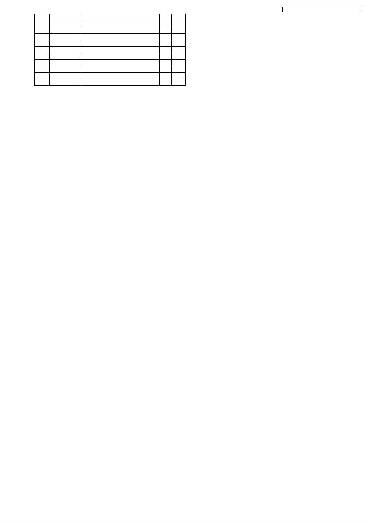
20 TAPE PLAYER PARTS
Ref.
No.
[8790A] Tape Dolby Block
ICs AND TRANSISTORs
IC1 YEAMCXA2565Q IC
Q401 YEANC114YKT Transistor
CAPACITORs
C201 YECUS1H331JM Ceramic, 330PF 50WV
C202 YECUS1H331JM Ceramic, 330PF 50WV
C204 YECUS1H123KX Ceramic, 0.012MF 50WV
C205 YECUS1E333KX Ceramic, 0.033MF 25WV
C206 YECUS1C104KX Ceramic, 0.1MF 16WV
C301 YECUS1H331JM Ceramic, 330PF 50WV
C302 YECUS1H331JM Ceramic, 330PF 50WV
C304 YECUS1H123KX Ceramic, 0.012MF 50WV
C305 YECUS1E333KX Ceramic, 0.033MF 25WV
C306 YECUS1C104KX Ceramic, 0.1MF 16WV
C401 ECA1CSA220I Electrolytic, 22MF 16WV
C402 ECEA1AKS330I Electrolytic, 33MF 10WV
C403 YECUV2A103KX Ceramic, 0.01MF 100WV
C404 YECUS1E333KX Ceramic, 0.033MF 25WV
C405 ECA1HSAR33I Electrolytic, 0.33MF 50WV
C406 YECUS1H472KX Ceramic, 0.0047MF 50WV
C407 ECEA1CKS100I Electrolytic, 10MF 16WV
C409 YECUS1H472KX Ceramic, 0.0047MF 50WV
C501 YECUV1E334ZF Ceramic, 0.33MF 25WV
RESISTORs
R201 ERJ6GEYJ683 Chip, 68k OHM 1/10W
R202 ERJ6GEYJ683 Chip, 68k OHM 1/10W
R207 ERJ8GEYJ181V Chip, 180 OHM 1/8W
R301 ERJ6GEYJ683 Chip, 68k OHM 1/10W
R302 ERJ6GEYJ683 Chip, 68k OHM 1/10W
R307 ERJ6GEYJ181 Chip, 180 OHM 1/10W
R402 ERJ6GEYJ183 Chip, 18k OHM 1/10W
R403 ERJ6GEYJ473 Chip, 47k OHM 1/10W
R404 ERJ8GEYJ334V Chip, 330k OHM 1/8W
R405 ERJ8GEYJ392V Chip, 3.9k OHM 1/8W
R406 ERJ6GEYJ273 Chip, 27k OHM 1/10W
R408 ERJ8GEYJ223V Chip, 22k OHM 1/8W
R409 ERJ6GEYJ273 Chip, 27k OHM 1/10W
R501 ERJ6GEYJ472 Chip, 4.7k OHM 1/10W
CONNECTORs
CN1 YEAE012385 Connector, 17P
CN3 YEAESLW05R1 Connector, 5P
SWITCHEs
SW1 K0J1CB00001 Switch
SW2 YEAS07174 Switch
SW3 YEAS08042 Switch
VARIABLE RESISTORs
VR201 EVNDXAA00B13 Variable Resistor
VR301 EVNDXAA00B13 Variable Resistor
[E8791] Tape Reel Block
DIODEs
TE1 YEADRPI221 Diode
TE2 YEADRPI221 Diode
CAPACITORs
C1 YECUS1H471JM Ceramic, 470PF 50WV
C2 YECUS1H471JM Ceramic, 470PF 50WV
C3 YECUS1H471JM Ceramic, 470PF 50WV
RESISTORs
R1 ERJ8GEYJ683V Chip, 68k OHM 1/8W
R2 ERJ8GEYJ683V Chip, 68k OHM 1/8W
R3 ERJ6GEYJ472 Chip, 4.7k OHM 1/10W
Part No. Part Name & Description Remarks
Ref.
No.
R4 ERJ8GEYJ472V Chip, 4.7k OHM 1/8W
R5 ERJ8GEYJ472V Chip, 4.7k OHM 1/8W
R6 ERJ8GEYJ472V Chip, 4.7k OHM 1/8W
R7 ERJ8GEYJ821V Chip, 820 OHM 1/8W
R8 ERJ8GEYJ821V Chip, 820 OHM 1/8W
CONNECTORs
CN2 YEAE0110TKCR Connector, 10P
JP3 YGAJ071387A CORD W/Connector
SWITCHEs
SW4 YEAS07174 Switch
SW5 EVQWJE001 Rotary Switch
Mechanical Parts
MISCELLANEOUS
1 YGFX0052472 Lock Plate Spring
2 YGFX0052454 Spring
3 YGFX0462100 Cassette Holder (U) Ass´y
4 YGFX0462104 Cassette Holder(L)
5 YGFA011830 Head Chassis Ass´y
6 YGFX234194 Cam
7 YGFX0052427 Back Tension Spring
8 YGFX209271 Reel (R) Ass´y
9 YGFX0052471 Holding Spring
10 YGJW04131 Washer
11 YGFX0052475 Lack Plate Spring
12 YGFX0031035 Lack Plate
13 YGFA011827 Main Chassis Ass´y
14 YGFX0052444 EQ Lever Spring
16 YGP0PT8790A0 Dolby P.C.B. Ass´y
17 YGP9FZ2973 Head Ass´y
18 YGFX0462105 Lever
19 YGFX0052478 Vibration-proof Spring
20 YGFX0052477 Spring
21 YGFX239470 Cassette Guid Plate
22 YGFX0462097 PRO Change Plate
23 YGFX0031031 Idler Gear Plate (F) Ass´y
24 YGP0FX3845 Main Motor Ass´y
25 YGFX0052474 Lack Return Spring
26 YGFX218305 Pinch Roller (F) Ass´y
28 YGFX0031033 Idler Gear Plate (R) Ass´y
29 YGFX0462102 Lack Return Link
30 YGFW062600 Lack Return Link Shaft
31 YGFX218306 Pinch Roller (R) Ass´y
32 YGFX213213 Flywheel Ass´y
33 YGFX0031001 Drive Gear (2)
34 YEFX003753B Play Idler Gear
35 YGFX014075 Lock Ling
36 YGFX003970 Gear
37 YGJT03250 Gear Shaft
38 YGFX0052446 Idler Gear Plate Spring
39 YGFX0031030 Worm Gear
40 YGP0FX3846 Loading Motor Ass´y
41 YGFX030102 Worm Gear Stopper
42 YGFX0031026 Drive Gear (3)
43 YGFA011851 Drive Chassis Ass´y
44 YGP0PT8791A0 Reel P.C.B. Ass´y
46 YGFX209270 Reel (F) Ass´y
47 YGFX0052473 Pinch Roller Spring
50 YGFX003971 PRO Change Gear
52 YEFR03083 Belt
54 YGFX0031029 Drive Gear
61 YEJE01004 E-Ring
62 YEJE01036 E-Ring
63 XYN2+J6FX Screw, 2 x 6mm
64 XYN2+C8FX Screw, 2 x 8mm
65 YEJT03167 Screw,
66 YEJS06097A Screw, 2 x 2.5mm
67 YEJT03271 Screw,
Part No. Part Name & Description Remarks
28
Page 29

21 EXPLODED VIEW (Tape Deck)
CUSTOM MADE FOR SUBARU / CQ-EF7160A
29
Page 30

CUSTOM MADE FOR SUBARU / CQ-EF7160A
22 WIRING DIAGRAM
22.1. Main Block (Top View)
E
BE
C
1
4
C
B
8
5
B
B
C
E
BE
B
C
C
E
C
E
B
B
B
C
E
C
C
E
B
E
C
E
B
C
E
16
1
2
7
8
B
C
E
B
C
E
BE
C
B
C
E
1
2
B
C
E
7
8
E
[E-6765Ea][T op Vie w]
50
80
C
B
30
100
4
E
C
B
B
C
E
C
8
B
C
E
B
C
E
B
C
8
3
1
4
5
E
B
C
B
BE
C
C
B
B
C
E
BE
C
E
BE
C
B
C
E
BE
C
E
CBE
B
E
C
B
C
E
E
C
B
C
B
B
C
E
E
B
C
E
1
2
E
3
4
5
[E-6765Eb][T op Vie w]
30
CQ-EF7160A Main P.C.B.
Page 31

22.2. Main Block (Bottom View)
CUSTOM MADE FOR SUBARU / CQ-EF7160A
[E-6765Eb][Bottom View]
[E-6765Ea][Bottom View]
CQ-EF7160A Main P.C.B.
31
Page 32

CUSTOM MADE FOR SUBARU / CQ-EF7160A
22.3. Display Block (Top View)
[E-8749Aa][T op Vie w]
CQ-EF7160A Display P.C.B.
32
Page 33

22.4. Display Block (Bottom View)
CUSTOM MADE FOR SUBARU / CQ-EF7160A
16
17
32
1
64
49
48
33
33
[E-8749Aa][Bottom View]
CQ-EF7160A Display P.C.B.
Page 34

CUSTOM MADE FOR SUBARU / CQ-EF7160A
22.5. Tape Block -1
1
2
E
C
B
16
17
1
2
4
5
9
8
16
17
24
1
32
25
[E-8790A]
[T op Vie w]
[E-8790A]
[Bottom View]
CQ-EF7160A FD04728 Tape Block
34
Page 35

22.6. Tape Block -2
CUSTOM MADE FOR SUBARU / CQ-EF7160A
[E-8791][T op Vie w] [E-8791][Bottom View]
CQ-EF7160A FD04728 Tape Block
35
Page 36

CUSTOM MADE FOR SUBARU / CQ-EF7160A
22.7. CD Servo Block
Horizontal Motor
BCE
[E-8586C] [Top V e w]
28
22
3
16
17
32
33
1
64
21
8
7
19
8
21
6
20
16
21
40
41
1
80
61
60
36
[E-8586C] [Bottom View]
CQ-EF7160A FD13096 CD Servo P.C.B.
Page 37

23 SCHEMATIC DIAGRAM-1
23.1. Tape Block
E-6765Ea
CN902
E-6765Ea
CN901
CUSTOM MADE FOR SUBARU / CQ-EF7160A
CQ-EF7160A FD04728 Tape Block
<Symbol T able>
37
Page 38

CUSTOM MADE FOR SUBARU / CQ-EF7160A
23.2. Display Block
5V
P-P
1mS, 2V/DIV
(1~43pin:2.5V)
5V
P-P
IC901
LCD DRIVER
YEAMLC75853
2mS, 2V/DIV
5V
P-P
2mS, 2V/DIV
0.9
5V
0.9
5V
P-P
P-P
0.9
3.9
1.7
0.5mS, 2V/DIV
3.7
5.1
2mS, 2V/DIV
0.9
0
0
0
4.4
0
0
0
0
0
B0ACCK000005
D900~903
CQ-EF7160A Display
PL901~PL907
YEALSTGG011A
To Main P.C.B.
E-6765Ea CN602
WB 2/PROG
BAS/TRE
To Main P.C.B.
E-6765Ea CN601
K0G123B00010
SW901~SW922
YEAS09285
TAPE.EJECT
38
Page 39

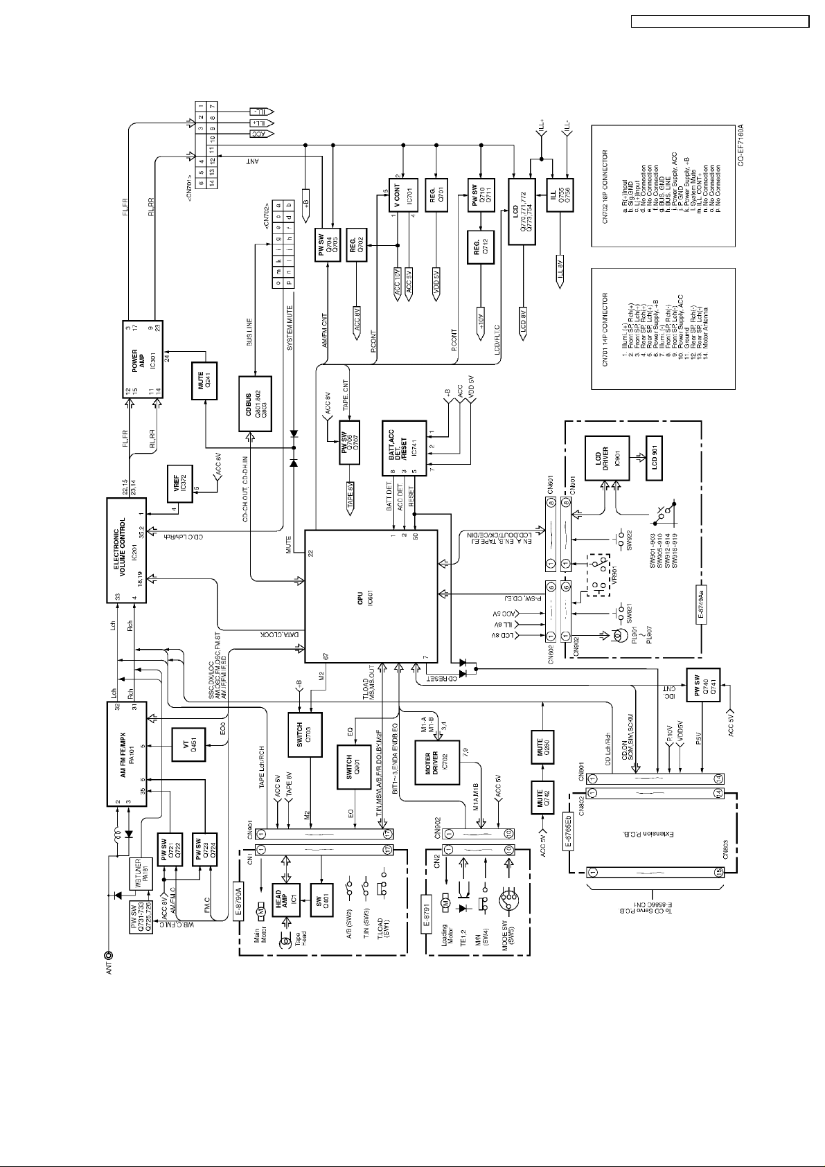
24 SCHEMATIC DIAGRAM-2
24.1. Main Block
CUSTOM MADE FOR SUBARU / CQ-EF7160A
39
Page 40

CUSTOM MADE FOR SUBARU / CQ-EF7160A
24.2. CD Servo Block
E-6765Eb CN803
40
CQ-EF7160A CD Servo Block
Printed in Japan (K) 2002. 1 (Recycled Paper)
 Loading...