

Page 1
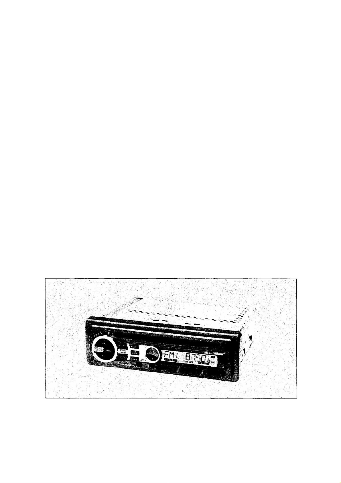
Operating Instructions
Bedienungsanleitung
Manuel d’instructions
Bruksanvisning
Manuale di istruzioni
Changer Control High-Power CD Player/RDS Receiver
RDS CD-Tuner; High Power; CD-Wechslersteuerung
Récepteur CD Pilote Changeur haute Puissance/Récepteur RDS
Hòg uteffekts CD/RDS radio med CD vàxiar styrning
Sinto/lettore CD High Power con RDS/controllo per cambia CD
CQ-DPG55LEN
Panasonic
Before operating this set, please read these instructions completely.
Bitte lesen Sie diese Bedienungsanleitung vor der Inbetriebnahme aufmerksam durch.
Nous vous recommandons de lire attentivement ces instructions avant d'utiliser cet appareil.
Läs noga dessa anvisningar fore apparatene användning.
Prima di adoperare Tapparecchio, vogliate leggere attentamente le istruzioni.
Page 2

Contents
Page
Precautions (ISO Connector).
Power and Sound Controls............................ 14
Radio Basics
RDS (Radio Data System) Reception
Compact Disc Player Bastes
CD Changer Basics
Remote Control Basics....................................30
Anti-Theft System
...................................................
........................................
..........................................
.........................
.............
...........................
4
16
18
26
28
34
Inhaltsverzeichnis
Seite
ISO-Anschlußschema-Achtung :Sehr wichtig....6
Stromversorgung und Klangregler...................44
Rundfunkempfang
Radio-Data-System (RDS)-Empfang
Grundlagen für die Bedienung des CD-Spielers.56
Grundlagen für die Bedienung des CD-Wechslers ... 58
Grundlagen für Fernbedienung
Diebstahlschutz
.........................................
..............
.......................
...............................................
46
48
60
64
Page
Installation
Electrical Connection.......................................40
Speaker Connections......................................41
Special Notes
Fuse............................................................... 43
Maintenance....................................................43
Specifications
Einbau
Elektrischer Anschluß......................................70
Anschluß der Lautsprecher
Besondere Hinweise........................................72
Sicherung
Pflege
Technische Daten............................................73
.......................................................
..................................................
..................................................
.............................................................
.............................
........................................................
..............................................................
37
42
43
Seite
67
71
73
73
Sommaire
Page
Précautions (Connecteur ISO)
Mise sous tension et commandes de son
Utilisation de la radio
Réception avec le système RDS
Utilisation de base du lecteur CD
Utilisation de base du changeur de CD
Utilisation de la télécommande
Système anti-vol
......................................
.............................................
........................
.......
....................
....................
..........
......................
8
74
76
78
86
88
90
94
InnehâlI
Sida
Observera (ISO-kontakter)
Ström- och ljudreglage
Grundläggande manövrering av radion
RDS-mottagning (datastyrd radiomottagning)
Grundläggande manövrering av CD-spelaren 116
CD-spelarens grundläggande funktioner
Grundläggande tiilvägagängssätt vid fjärrstyrning.. 120
Stöldskyddsanordning
.............................
.................................
.........
.......
...................................
10
104
106
..........
118
124
108
Page
installation
Connexions éiectriques
Connexion des haut-parleurs
Remarques spéciales
Fusible........................................................ 103
Entretien
Spécifications.................................................103
Montering
Elektriska ansiutningar
Anslutning av högtalare
Speciella anmärkningar
Säkring
Underhàll
Tekniska data
......................................................
.................................
........................
....................................
........................................................
.....................................................127
.................................
.............................
................................
.........................................................
......................................................
...............................................
97
100
101
102
103
Sida
130
131
132
133
133
133
CQ-DPG55LEN
Page 3
Contenuto
Pag.
Precauzioni (Connecttore ISO)........................12
Comandi di alimentazione e del suono
Funzionamento della radio
Ricezione RDS (Radio Data System)
Funzionamento del lettore CD
Operazioni fondamentali del cambiadischi CD.... 148
Fondamenti dei telecomando
Sistema antifurto............................................154
............................
......................
........................
..........
............
134
136
138
146
150
Pag.
Installazione
Collegamenti elettrici
Collegamento diffusori
Note speciali..
Fusibile..........................................................163
Manutenzione.............................................. 163
Dati tecnici.....................................................163
................................................
...........
...............................................162
.........................
..................................
157
160
161
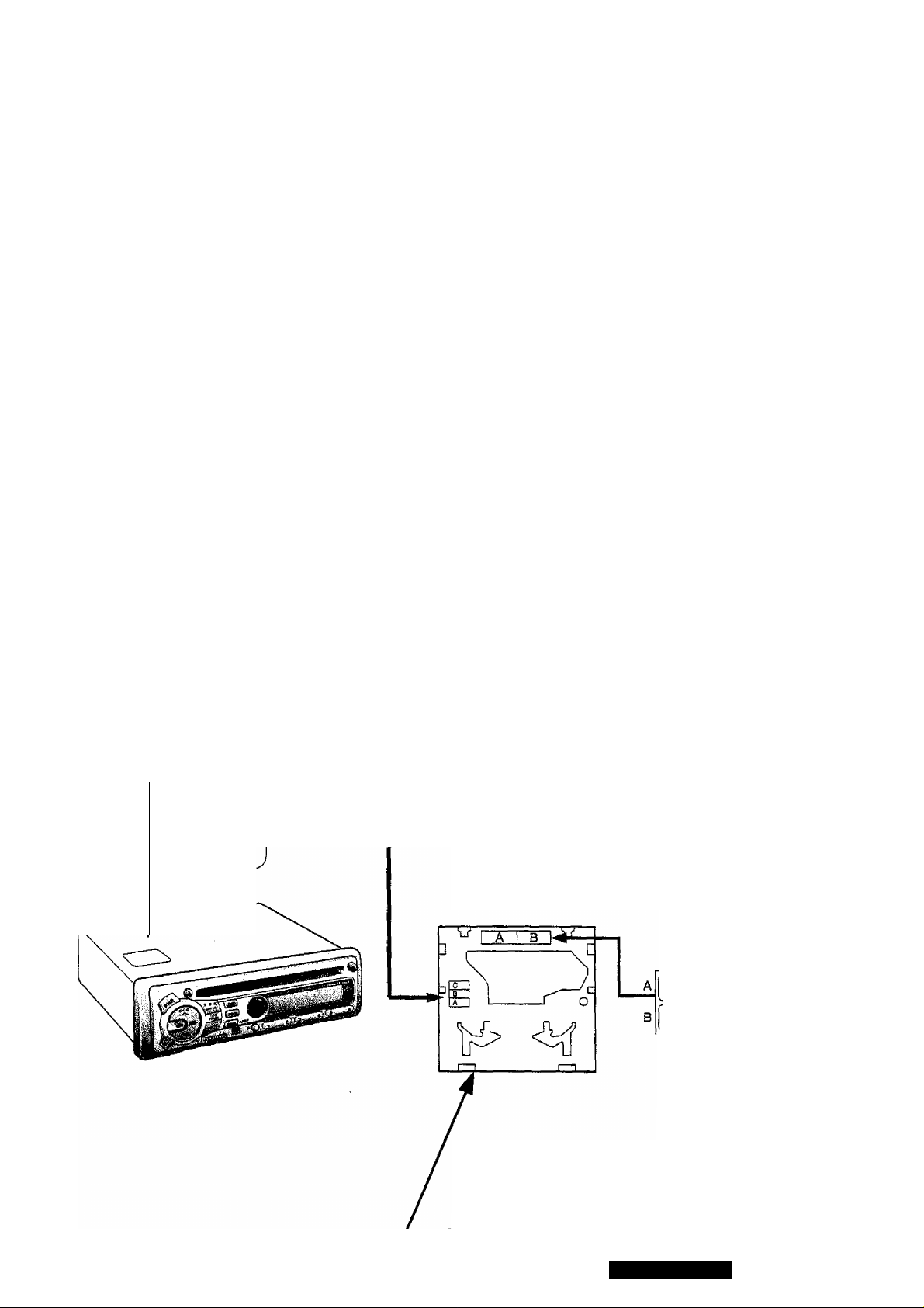
• Label Indications and Their Locations
• Warnetiketten und deren Anbringungsort
• Indications portées les étiquettes et
emplacement
• APPAREIL A LASER DE CLASSE 1
• KLASS 1 LASER APPARAT
• LUOKAN 1 LASERPLAITÊ
CLASS
LASER
K
—^
1
PRODUCT
r
VORSICHT!
A) ADVERSEU
B) VARNINGI
C) VARO!
• Varningsskyltarna, och deras placering
• Indicazioni delie etichette e le ioro posizioni
UNSICHTBARE LASERSTRAHLUNG, WENN
ABDECKUNG GEÖFFNET IST, NICHT DEM
LASERSTRAHL AUSSET2EN.
Usynlig lasersträling när deksel äpnes og
sikKerhedsläs brytes. Unngä eksponering for
strälen.
Osyniig iasersträining när denna de! är öppnad
och Sparren är urkopplad. Betrakta ej strälen.
Avattaessa ja suojalukitus ohitettaessa ölet alttiina näkymättömälle lasersätellylle. Älä katso
säteeseen.
DANGER ' tnvbfell liMr raiAatlan WiMfi opan.
AVOID DIRECT EXPOSURE TO BEAR
AOVERSEL ‘ UiynSgtlUHlys mttiàln wd
ibnln^UNDOA DIREKTE BESTWAlNIMG.
• Caution Mark
• Warnzeichen
• Marque d'avertissement
• Varningsmärke
• Marca di precauzione
• Deck Ass’y (Upper Side)
• Geràteansicht (Oberseite)
• Assemblage de la table lecture (Côté supérieur)
• Dâcksenhet (Topp)
• Gruppo della piastra (Lato superiore)
CQ-DPG55LEN
Page 4
Precautions (ISO connector)
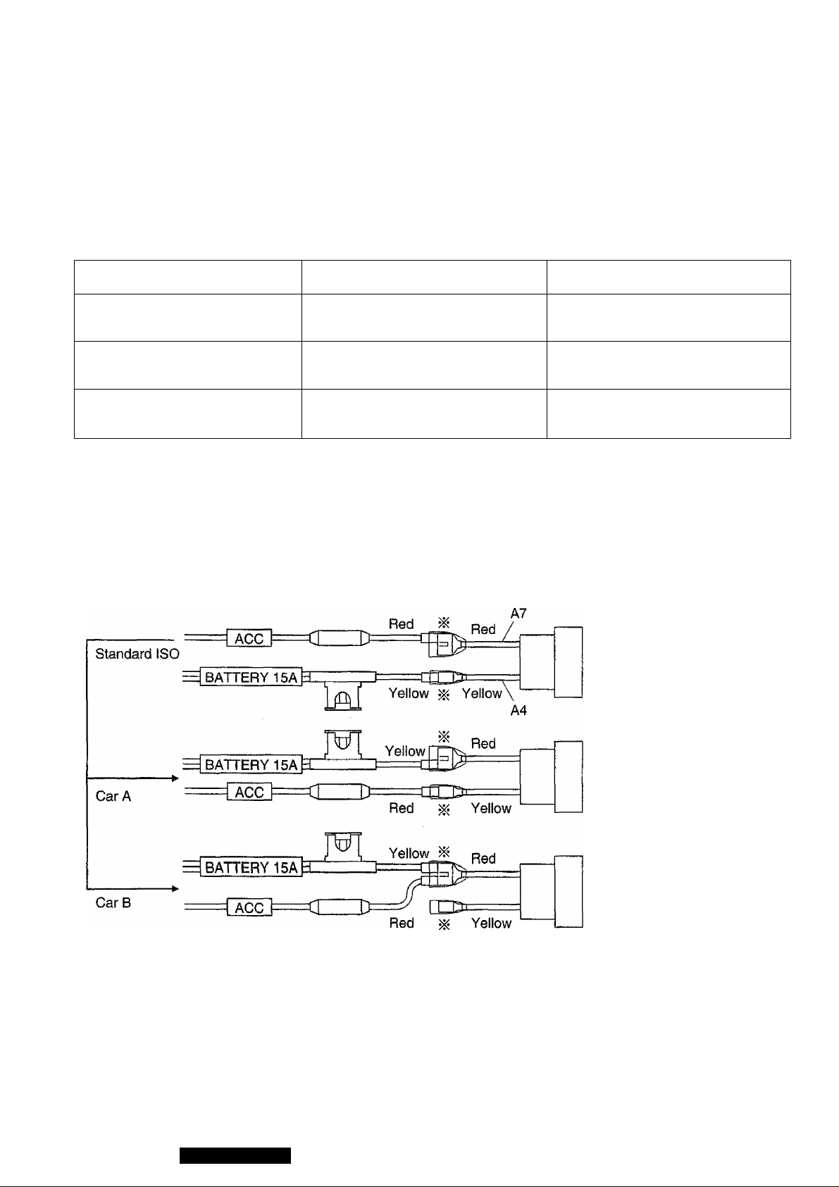
• Wiring for the power connector conforms to the arrangement of standard ISO connectors,
® In case of some car types, the arrangement of connector may differ from the standard ISO as
shown in Table 1, even though ISO connectors are adopted.
Table 1
Car for standard ISO
In case of Car type A
In case of Car type B
A4
Battery
(permanent 12 V supply)
“IGN”or‘ACC”
(switched 12 V supply)
No Connection
(switched 12 V supply)
(permanent 12 V supply)
(permanent 12 V supply)
A7
‘1GN”or‘ACC”
Battery
Battery
e Make sure the ISO connector arrangement in your car side is as same as the standard ISO.
(Table 1, Fig. 1)
® In case of arrangement for Car type A or B, change connections of the red/yellow leads at the
re-connectable joint (iii) as shown in Fig.1.
Fig.1
A7: ACC/IGN Switch
° +12V
A4 : +12V Battery
A7 : +12V Battery
A4 : ACC/IGN Switch
---------
-----------------------
A7 : +12V Battery
A4 : NC
• After fix the connections, the part should be insulated with electrical tape to keep away
from unit damage.
+12V
CQ-DPG55LEN
Page 5

Panasonic welcomes you to their constantly growing family of electronic products owners.
We endeavor to give you the advantages of precise eiectronic and mechanicai engineering, manufactured
with carefully selected components, and assembled by people who are proud of the reputation their work
has buiit for our company. We know this product wiil bring you many hours of enjoyment, and after you dis
cover the quality, value, and reliability we have built into it, you too will be proud to be a member of our fami-
iy-
Precautions
Volume Level
For your driving safety, keep the volume level iow
enough to be aware of road and traffic conditions.
Car Washing
To avoid electrical shorts which may cause fire, or
other damage, do not expose this equipment
(including the speakers and CDs) to water or exces
sive moisture.
Car Ventilation
If your car is parked for several hours in direct sun
light, the temperature inside the car may become
very high. It is advisable to drive the car and give
the interior a chance to cool down before switching
the unit on.
Power Supply
This equipment is designed to be used in a car hav
ing 12-Volt negative ground battery system.
Disc Mechanism
Do not insert coins or any small objects. Keep
screwdrivers and other metallic objects away from
the disc mechanism and disc.
Service
This unit is made of precision parts. Do not attempt
to disassemble or adjust any parts. For repair,
please consult your nearest authorized Panasonic
Service Center.
Note:
The preset memory is cleared to return to the origi
nal factory setting when the power connector or bat
tery is disconnected.
Laser Products
Caution;
This product utilizes a laser.
Use of controls or adjustments or perfor
mance of procedures other than those spec
ified herein may result in hazardous radia
tion exposure.
Do not take apart this unit or attempt to make any changes yourself.
This unit is a very intricate device that uses a laser pickup to retrieve information from the surface of com
pact discs. The laser is carefully shielded so that its rays remain Inside the cabinet.
Therefore, never try to disassemble the player or alter any of its parts since you may be exposed to laser
rays and dangerous voltages.
Laser products:
Wave Length 780 nm
Laser Power No hazardous radiation is
emitted with safety protection.
CQ-DPG55LEN
Page 6
ISO-Anschlußschema-Achtung: Sehr wichtig
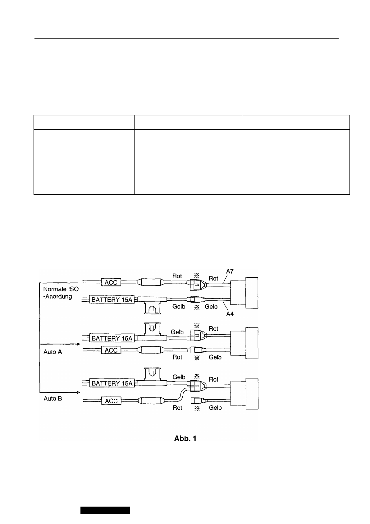
• Die Verdrahtung des mitgelieferten Stromkabeis entspricht der Anordnung der normalen ISOSteckverbinder.
® Bei einigen Autotypen kann es Vorkommen, daß die Verdrahtung anders als die aus der
Tabelle 1 ersichtlichen ISO-Anordnung ist, obwohl ISO-Steckverbinder verwendet werden.
Tabelle 1
—----------_^^AbbJ^^tif^
Auto für normale ISO-
Anordnung
Beispiel Auto A
Batterie (ständige 12V-
Stromversorgung)
“IGN” oder “ACC” (umgeschal
tete 12V-Stromversorgung)
Beispiel Auto B Kein Anschluß
A4
A7
“IGN” oder “ACC” {umgeschal
tete 12V-Stromversorung)
Batterie (ständige 12V-
Stromversorgung)
Batterie (ständige 12V-
Stromversorgung)
® Die Daten überprüfen, um sicherzustellen, daß die Anordnung der ISO-Steckverbinder auf
der Autoseite die gleiche ist wie die normale ISO-Anordnung (Tabelle 1, Abb. 1).
• Im Falle der Anordnung für Auto A oder B die Anschlüsse der rot/gelben Kabel am Übertra-
gungs-Sieckverbinderblock gemäß Abb. 1 ändern.
A7: Zündschalter
(ACC/IGN)
---------
+12 V
A4: +12V-Batterie
X
A7; +12V-Batterie
A4: Zündschalter
(ACC/IGN)
---------
+12V
A7: +12V-Batterie
A4: Kein Anschluß
Nach der Verkabelung sollte unbedingt der durch ^ gekennzeichnete Teil mit Hilfe von
Isolierbändern o.ä. isoliert werden.
CQ-DPG55LEN
Page 7

Lieber Panasonic-Kunde
Wir möchten Ihnen dafür danken, daß Sie sich für dieses Gerät entschieden haben. Wir heißen Sie hiermit herzlich
willkommen in der ständig wachsenden Familie zufriedener Besitzer von Panasonic-Geräten in der ganzen Welt.
Wir sind sicher, daß mit dieser Neuerwerbung alle ihre Ansprüche befriedigt werden.
Lesen Sie bitte diese Bedienungsanleitung sorgfältig durch, und halten Sie sie immer griffbereit. Denn sie enthält eine
Anzahl wichtiger Hinweise, die gewährleisten, daß Sie die Möglichkeiten ihres Gerätes voll ausnutzen können.
Vorsichtsmaßnahmen
Lautstärkepegel
Aus Gründen der Fahrsicherheit ist der Lautstärke
pegel so einzustellen, daß auch andere
Verkehrsgeräusche (Hupen, Warnsignale) vernom
men werden können.
Autowäsche
Dieses Gerät (einschließlich Lautsprecher und CD)
vor Wasser und übermäßiger Feuchtigkeit
schützen, um elektrischen Kurzschlüssen vorzubeu
gen.
Belüftung
Falls Ihr Wagen längere Zeit in direktem
Sonnenlicht geparkt ist, könnte sich das innere sehr
stark erwärmen. In einem solchen Fall sollte das
Fahrzeug mit geöffneten Fenstern für einige Zeit
gefahren werden, damit sich das Wageninnere ab
kühlen kann. Erst danach das Gerät einschaiten.
Stromversorgung
Dieses Gerät darf nur in Fahrzeuge mit 12 VBatterie und negativer Batterieklemme an Masse
eingebaut werden.
CD-Laufwerk
Keine Münzen oder kleine Gegenstände in das
Gerät einstecken. Schraubenzieher und andere me
tallische Gegenstände vom CD-Lautwerk und den
CDs fernhalten.
Kundendienst
Dieses Gerät ist aus Präzisionsteilen zusammengesteltt. Niemals selbst das Gerät zerlegen bzw.
einzelne Teile einstellen.Für Reparaturen wenden
Sie sich bitte an den Panasonic Kundendienst.
Hinweis:
Beim Trennen des Versorgungssteckers oder der
Batterie wird der Voreinstellungsspeicher gelöscht
und die ursprüngliche Werkseinsteilung wird wieder
aktiv.
Laser Erzeugnisse
Vorsicht;
Dieses Gerät arbeitet mit Laserstrahlen.
Benutzung der Bedienungseiemente anders als
in der Bedienungsanleitung beschrieben oder
Veränderungen der Betriebsweise können zu
gefährlicher Strahlenaussetzung führen.
Öffnen Sie dieses Gerät nicht, und versuchen Sie unter keinen Umständen, am Gerät herumzubasteln.
Dieses Gerät ist ein sehr kompiiziertes Instrument, das einen Laserstrahl benutzt,um die auf der Oberfläche der CDs
gespeicherten Informationen abzulesen. Der Laserstrahl ist sorgfältig abgeschirmt, so daß die Strahlung innerhalb
des Gerätes verbleibt.
Aus diesem Grunde öffnen Sie das Gerät auf keinen Fall, und versuchen Sie unter keinen Umständen Geräteteiie zu
verändern. Sie können sich unter Umständen gefährlicher Strahlung und Stromspannung aussetzen.
Laser-Erzeugnisse:
Wellenlänge 780 nm
Laser Energie
Mit Sicherheitsschutz ent
weicht keine gefährliche
Strahlung.
CQ-DPG55LEN
Page 8
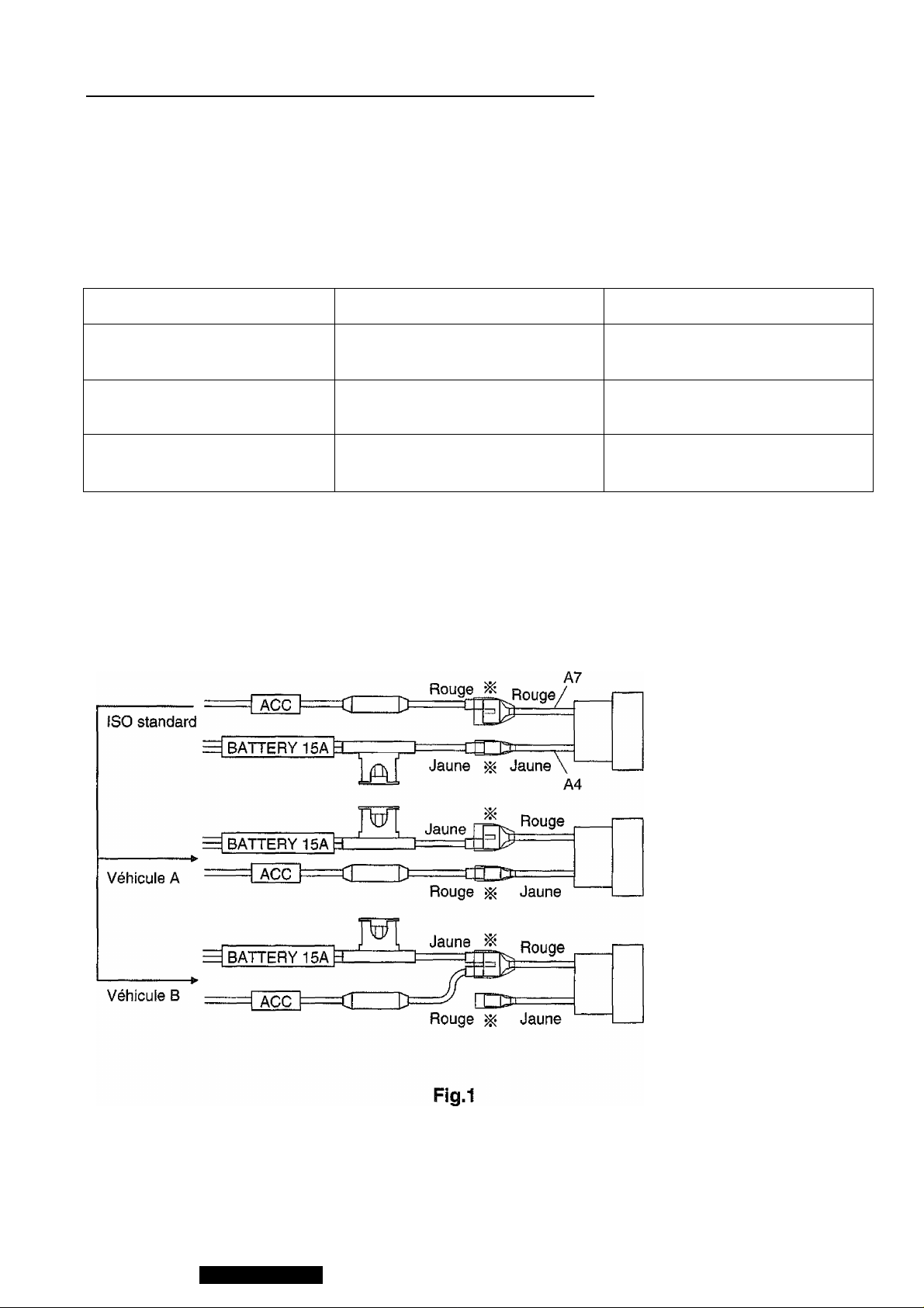
Précautions (Connecteur ISO)______________
® Le câblage pour le cordon d’alimentation prévu en accessoire se conforme à l’alignement des
connecteurs standard ISO.
® Pour certains types de véhicules, une partie de câblage peut différer de l’alignement standard
ISO comme l’indique le Tableau 1, même si les connecteurs ISO sont adoptés.
Tableau 1
broche sur la ^’9^
Véhicule pour l’alignemeiit
standard ISO
Exemple de véhicule A
Exemple de véhicule B
Batterie (alimentation perma
nente en 12 V)
“IGN” ou “ACC” (alimentation
en 12 V sélectionnée)
Absence de connexion
A4 A7
“IGN” ou “ACC” (alimentation
en 12 V sélectionnée)
Batterie (alimentation perma
nente en 12 V)
Batterie (alimentation perma
nente en 12 V)
® Vérifier les données pour s’assurer que l’alignement de connecteur ISO du côté véhicule est
identique à celui standard ISO (Tableau 1, Fig. 1).
® En cas d’alignement pour le véhicule A ou B, changer les connexions des conducteurs
rouges/jaunes au bloc connecteur de transfert (-X*) comme le montre la Fig. 1.
A7 : Sélecteur ACC/IGN
---------
-----------------------
+12V
A4 : Batterie +12 V
A7 ; Batterie +12 V
A4 : Sélecteur ACC/IGN
---------
-----------------------
T—
A7 : Batterie +12 V
A4 : Non connecté
«Après les opérations, les parties marquées par un astérisque (^) doivent être isolées sans
faute en utilisant des rubans isolants ou des matériaux similaires.
+12V
8
CQ-DPG55LEN
Page 9

Panasonic vous souhaite la bienvenue parmi ia famiile toujours croissante des possesseurs de nos
appareils électroniques. Nous avons fait de notre mieux pour vous apporter les avantages de la précision
mécanique et électronique de pointe, étant donné que l’appareil a été composé avec des pièces
soigneusement choisies et montées par des gens qui sont fiers de la renommée de leur Société que leur
travail consciencieux lui a value. Nous sommes sûrs que cet appareil vous permettra de profiter de nom
breuses heures d’écoute, et après avoir découvert la qualité intrinsèque et ia fiabilité de l’appareil, vous
serez vous aussi fier d’appartenir à la famiile Panasonic.
Précautions
Niveau du voiume
Par mesure de sécurité routière, maintenez le
niveau de volume assez bas pour pouvoir entendre
les bruits de la rue.
Nettoyage de la voiture
Pour éviter les court-circuits électriques qui peuvent
provoquer un incendie ou autre dommage, n’ex
posez pas l’appareil (y compris les hautparleurs, les
CDs) à i’eau ou à une humidité excessive.
Ventilation de la voiture
Si votre véhicule est stationné pendant plusieurs
heures au soleil, la température intérieure peut être
très élevée.Pour revenir au mode de température
normal, il est recommandé de conduire un certain
temps avant de mettre l’appareil sous tension.
Alimentation
Cet équipement est conçu pour fonctionner avec du
12 V cc, masse négative.
Méchanisme d’entrainement du disque
Ne pas introduire de pièce de monnaie ou tout autre
petit object. Eloigner les aimants, tournevis et
autres objets métalliques du mécanisme
d’entraînement et du disque.
Entretien
Cet appareil est conçu à partir d’éléments de pré
cision. N’essayez pas de démonter ces éléments.
Pour l’entretien, adressez-vous à votre service d’en
tretien Panasonic le plus proche.
Remarque:
Les présélections mémorisées sont effacées pour
revenir aux sélections initiales en usine lorsque le
connecteur d’alimentation ou la batterie est déb
ranché.
Charactéristiques du dispositif laser
Attention:
Ce produit utilise un laser.
L’utilisation des commandes, le réglage ou te fonc
tionnement, suivant les procédures différentes de
celles exposées ci-dessus peuvent entraîner une
exposition dangereuse aux radiations.
Ne pas démonter cet appareil ni y apporter de modifications vous-même.
Cet appareil est un dispositif très complexe utilisant une tête de lecture laser pour extraire des informa
tions de la surface des disques compacts.
Le laser est soigneusement protégé de telle manière que le faisceau laser reste à l’intérrieur du coffret.
Par conséquent, ne jamais essayer de démonter le lecteur ni modifier une de ses parties étant donné que
vous pourriez ainsi être exposé au faisceau laser et à des tensions dangereuses.
Caractéristiques du dispositif laser:
Longueur d’onde 780 nm
Puissance Aucune radiation nocive n’est
émise avec protection de
sécurité.
CQ-DPG55LEN
Page 10
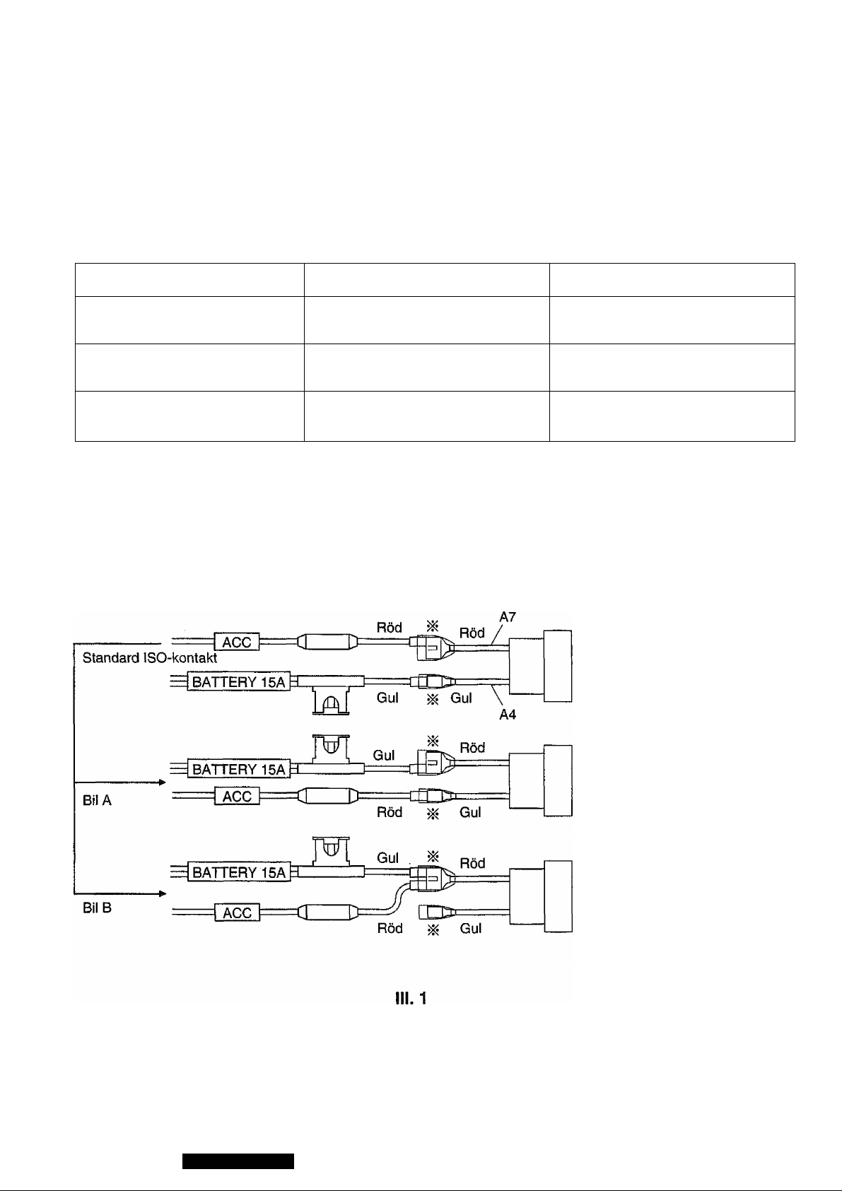
Observera (ISO-kontakter)
• Kontrollera att kablarna for tändningens strömkabel är korrekt utformade for anpassning till
Standard ISO-kontakter.
® 1 en del typer av bilar kan det hända att vissa kabtar skiljer sig frän anpassningen tili Standard
ISO-kontakter pä det satt som framgär av tabeli 1, även om ISO-kontakter används.
Tabeli 1
Bil for anpassning till stan
dard ISO-kontakt
Exempel pâ bil A
Exempe! pâ bil B
A4
Batteri (ständig, 12 V
strömförsörjning)
Tändning (omkopplad, 12 V
strömförsörjning)
Ingen anslutning
Tändning (omkopplad, 12 V
strömförsörjning)
Batteri (ständig, 12 V
strömförsörjning)
Batteri (ständig, 12 V
strömförsörjning)
A7
• Kontrollera data for att bekràfta att anpassningen till ISO-kontakter pâ bilens kablar
overensstammer med anpassningen till standard ISO-kontakter (tabeli 1/ill. 1).
® Àndra den rôda och den gula kabelns anslutningar till overforingskontakten (^*) sâsom visas
pâ ill. 1, nàr anpassning for bil A eller bil B galler.
A7 : tandningsomkopplare
---------
-----------------------
+12V
^—A4 : +12 V batteri
A7 ; +12 V batteri
A4 : tändningsomkopplare
------
o''"^o
-------+12V
A7 ! +12 V batteri
— A4 : ingen anslutning
® Kontakterna märkta ^ mäste alltid isoleras med hjälp av isoleringstejp elier liknande, efter
slutförda anslutningar.
10
CQ-DPG55LEN
Page 11

Välkommen till den ständlgt växande gruppen av ägare tili Panasonic elektroniska Produkten Varje Pro
dukt tillverkas av noggrant utvalda komponenter och sammansätts av välutbildad personal under sträng
kvalitetskontroll.
Las bruksanvisningen noga och iär apparaten väi innan den används.
Observera
Volym
Anpassa ljudvolymen sä att säker bilkörning ej hindras.
Biltvättning
För att undvika kortsiutningar sot^i kan resulterà 1
brand elier annan skada, fär apparaten (inklusive
högtaiarna och skivorna) inte utsättas för vatten
eller fukt.
Ventilation inom bilen
Är det mycket varmt i bilen, kör den dà en stund för
att sänka temperaturen innan apparaten kopplas
pä.
Strömförsörjning
Apparaten far enbart anslutas tili ett fordon vars
elektriska system är 12 V likspänning och negativ
jordning.
Skyvmekanism
Stoppa inte in mynt eller andra smäföremäl, Häli,
skruvmejslar och andra metallföemäl borta frän
skyvmekanismen och skivor.
Service
Apparaten är tillverkad av precisionsdelar.Tag aldrig
isär eller justera nägonting själv.För reparation,
lämna apparaten tili en Panasonic-äterförsäljare.
Anm:
Observers att samtliga uppgifter, som iagrats i minnet, ätergär till de inställingar som gjordes före bilstereons leverans frän fabriken när strömkabeln
eller batterikabelen kopplas ur.
Om laserprodukter
Att observera:
En lasersträle används i denna produkt.
Användandet av reglage och utförandet av justeringar/tlllvägagängssätt, som Inte beskrivs i denna
bruksanvisning, kan bli orsak tili farlig sträining.
Denna apparat fär inte plockas isär och Inga ändringar fär utföras av konsumenten.
Denna apparat är en mycket komplicerad anordning som nyttjar en lasersträle för upptagning av Informa
tionen frän CD-skivans yta. Lasern är noggrant avskärmad sä att dess strälar förbiir innanför
apparathöljet. Därför fär CD-spelaren inte tagas isär eller nägon av dess delar andres eftersom du kan
utsättas för lasersträten och hög spanning.
VARNING! Om apparaten används pä annat sätt än i denna bruksanvisning specificerats, kan
användaren utsättas för osyniig lasersträining, som överskrider gränsen för laserklass 1.
VAROITUS! Laitteen käyttäminen muulia kuin tässä käyttöohjeessa mainitulia tavalla saattaa altistaa
käyttäjän turvaliisuusluokan I ylittävälle näkymättömälle lasersäteiiylte.
Lasersträlens egenskaper:
Väglängd 780 nm
Lasereffekt
Ingen farlig sträining avges med
skyddssäkringarna intakta.
CQ-DPG55LEN
11
Page 12
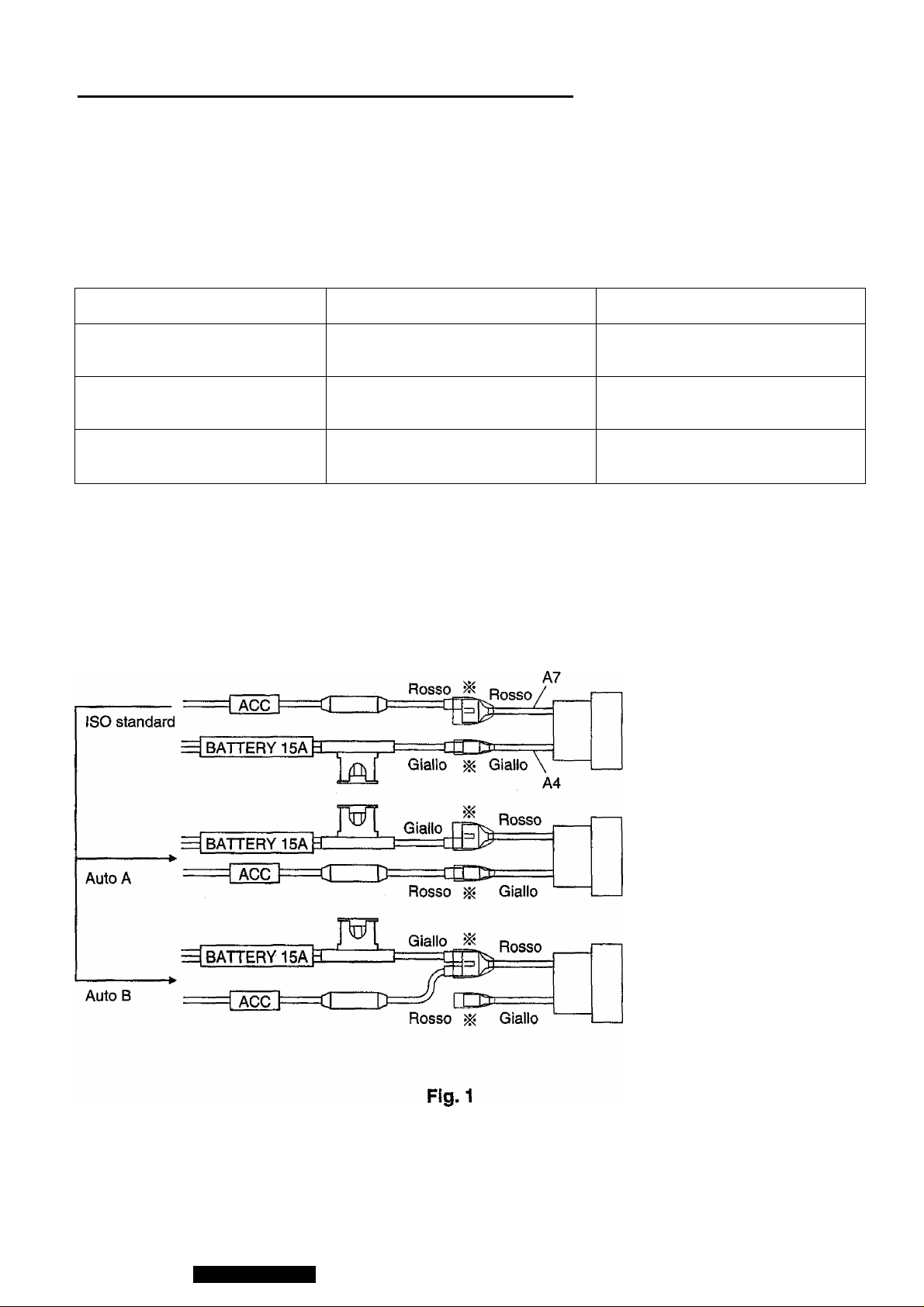
Precauzioni (Connettore ISO)
______________
• Il cablaggio per il cavo di alimentazione accessoria è conforme ali'allineamento dei collegamenti ISO standard.
« Per alcuni tipi di auto, parti del cablaggio possono differire dairallineamento ISO standard
mostrato nella tabella 1, anche se sono impiegati connettori ISO.
Tabella 1
Auto per allineamento ISO
standard
Esempio di auto A
Esempio di auto B
A4
Batteria (12 V forniti continua
mente)
"IGN"o"ACC" (12 V forniti a
commutazione)
Nessun collegamento
"IGN" o"ACC" (12 V forniti a
commutazione)
Batteria (12 V forniti continua-
Batteria (12 V forniti continua-
A7
mente)
mente)
• Controllare i dati per verificare che l'allineamento connettori ISO sul lato dell'auto sia uguale
ali'allineamento ISO standard (Tabella 1, Fig. 1).
9 Nel caso dell'allineamento per auto A o B, cambiare il collegamento del cavi rosso/giallo al
blocco connettore di transferimento (')K) come mostrato nella Fig. 1.
Ai: InterruttoreACC/IGN
---------
-----------------------
%
A4 : Batteria +12 V
+12V
A7 : Batteria +12 V
A4 : Interruttore ACC/IGN
+12V
^—A7 : Batteria +12 V
A4 : Non collegato
• Dopo l'operazione la parte indicata da ^ deve essere assolutamente isolata, usando nastro
isolante 0 simili.
12
CQ-DPG55LEN
Page 13

Panasonic Vi dà il benvenuto nella famiglia in costante aumento dei proprietari dei suoi prodotti elettroni
ci. Noi cerchiamo sempre di offrirvi i vantaggi di una tecnica elettronica e di una meccanica perfetta nei
nostri prodotti fabbricati con componenti altamente selezionati e lavorati da persone che godono di piena
fiducià presso la nostra compagnia. Noi siamo sicuri che questo prodotto Vi offrirà molte ore piacevoli e
che dopo averne scoperto la qualità, il valore e l’affidabilità, anche Voi sarete orgogliosi di essere un
membro della nostra famiglia.
Precauzioni
Livello del volume
Per la vostra sicurezza quando portate l'automobile,
tenete i! volume su un livello abbastanza basso per
poter sentire il suoni di awertimentb del traffico.
Lavaggio deirautomobile
Per evitare cortocircuiti elettrici, che potrebbero
causare incendi o altri danni, non esponete quest’u
nità (inclusi gii altorparlanti, i dischi) all’acqua o ad
eccessive quantità di umidità.
Ventilazione deirautomobile
Nel caso in cui lasciate l’automobile parcheggiata
per parecchie ore nella luce diretta del sole, la tem
peratura all’interno deirautomobile può diventare
molto alta. Per far ritornare la temperatura interna
ad un livello normale, è consigliabile guidare l’auto
mobile un po’ di tempo prima di accendere l’unità.
Alimentazione
Quest’unità è stata disegnata per essere alimentata
con 12 V di corrente continua, massa negativa.
Meccanismo del dischi
Non inserire delle moneto o altri oggetti piccoli.
Allontanare i cacciaviti ed altri oggetti metallici dal
meccanismo del dischi e dai dischi.
Servizio
Quest’unità è stata costruita con parti di precisione.
Non cercate di smontare o aggiustare queste parti.
Per il lavori di servizio, consultate il più vicino centro
assistenza della Panasonic.
Nota:
Quando si stacca il cablaggio o la batteria, la
memoria di preselezione si cancella e torna la rego
lazione operata in fabbrica.
Prodotti laser
Precauzione:
Questo prodotto utilizza un laser.
L’impiego dei comandi o regolazioni, o una essecuzione dei procedimenti diversi da quelli speci
ficati in questo manuale possono risultare in una
esposizione pericolo sa a radiazioni.
Non smontare quest’unità o tentare di eseguire dei cambiamenti da solo.
Quest’unità è un apparecchio con pezzi di precisione che usa un pick-up con laser per ricevere dati dalla
superficie dei compact disc. Il laser viene protetto con cura di modo che rimanga all’interno dei mobiletto.
Si raccomanda quindi di non smontare la piastra o esseguire delle modificazioni con i suoi componenti
poiché procedendo cosi si può esporsi al raggio del laser ed alie tensioni pericolose.
Prodotti laser:
Lunghezza d’onda
Potenza dei laser
780 nm
Nessuna radiazione peri
colosa viene emessa con
una protezione di sicurezza.
CQ-DPG55LEN
13
Page 14
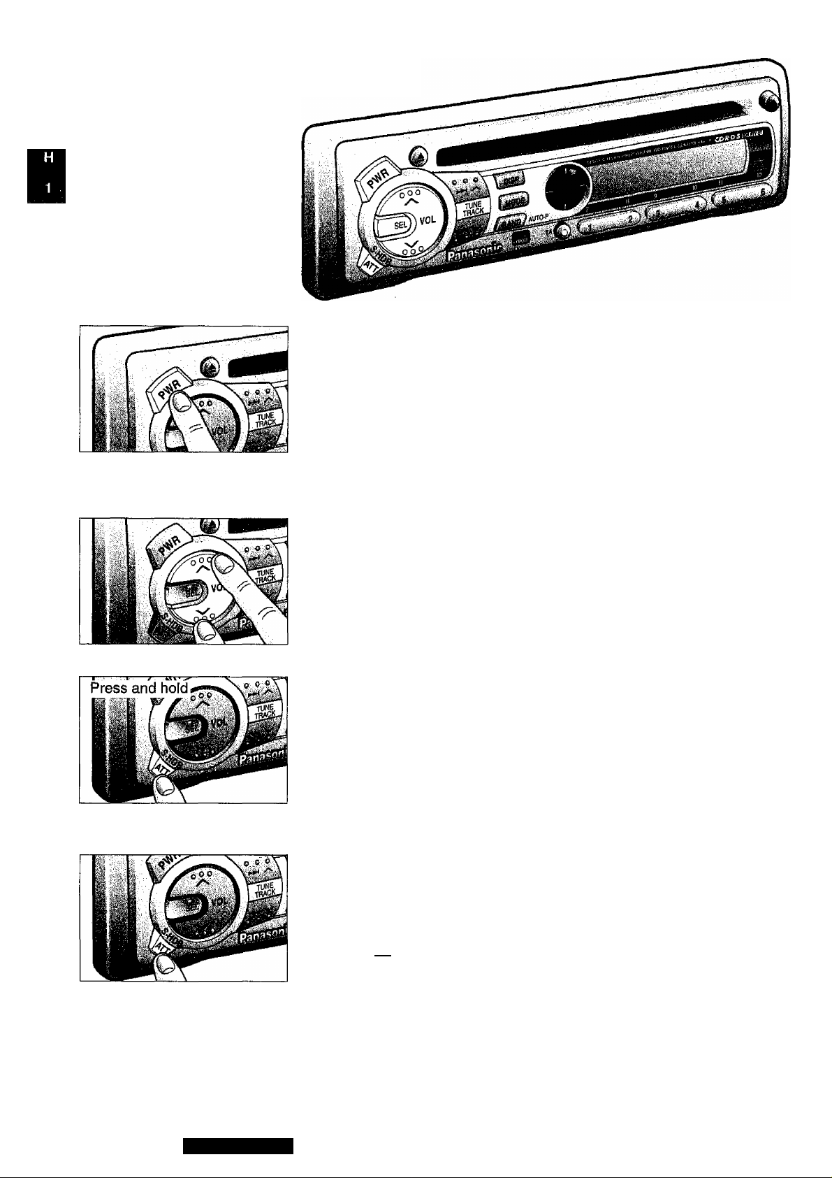
n Power and Sound H Controls
Power
If the car is not already running, turn the key in the ignition until the
accessory indicator lights.
Press PWR to switch on the power.
Press and hold PWR again to switch off the power.
Note: When power is switched on for the first time, demonstration display
appears. To release this display, press DISP.
R1Í B15G "
Volume
Press “VOLA” or “ VVOL” to increase or decrease volume.
lu
Oto 40
Press “VOLA” or “VVOL” for more than a half second to sequential
ly change numeric levels on the display.
•Volume Level
S*HDB (Super High Definition Bass)
Especially for rock music, the bass-sound will be more powerful.
• Press and hold ATT for more than 2 seconds to be able to listen to
high-definition bass.
• Press and hold ATT for more than 2 seconds again to cancel.
Attenuator
• Press ATT to decrease volume to about 1/10 of the previous level.
14
rm.
• Press ATT again to cancel.
Note: This unit is equipped with anti-volume-blast circuit which serves as an automatic volume level
adjuster so that you will not be deafened with sudden loud volume.
This system operates as below. When PWR is first pressed to switch on, the volume level is low. After
that, the volume level gradually returns to the level when the switch is turned off.
Anti-volume-blast circuit is not effective when volume level is lower than position 20 at the display.
CQ-DPG55LEN
Page 15
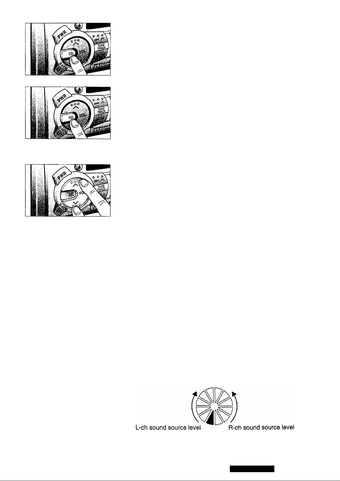
Changing Audio Modes
Press SEL to switch the audio mode in the following order.
Normal Mode VOL ^ BAS ^ TRE BAL FAD
t
___________________
Sr
Bass and Treble
Press SEL to select the BASS (TREBLE) mode. Press “VOL A” or “V
VOL” to increase or decrease the bass (treble) response.
JR5-^ 3d3
-12 to+12
Tf?Ef a
-12 to+12
Balance
Press SEL to select the BALANCE mode. Press “VOLA” or “VVOL”
to shift the sound volume to the right or left speakers.
m i ¿?
1 to 15
WLCNT
Balance Center
m p a
1 to 15
Fader
Press SEL to select the FADER mode. Press “VOLA” or “VVOL” to
shift the sound volume to the front or rear speakers.
. , ..... ■.[
1to15
FRU CNT
Fader Center
FBI f? p
1 to 15
Note: When a Audio control mode (BAS/TRE/BAL/FAD) is selected but no operation is made within 5
seconds (2 seconds at VOL mode), the display will return to the normal operation (Radio, CD, CD
Changer) mode. In such a case, press SEL again to select the control mode.
Level Meter
When power is ON, the level of sound sources, such as radio and
CD, is displayed by the level meter shown below at all times.
CQ-DPG55LEN
15
Page 16
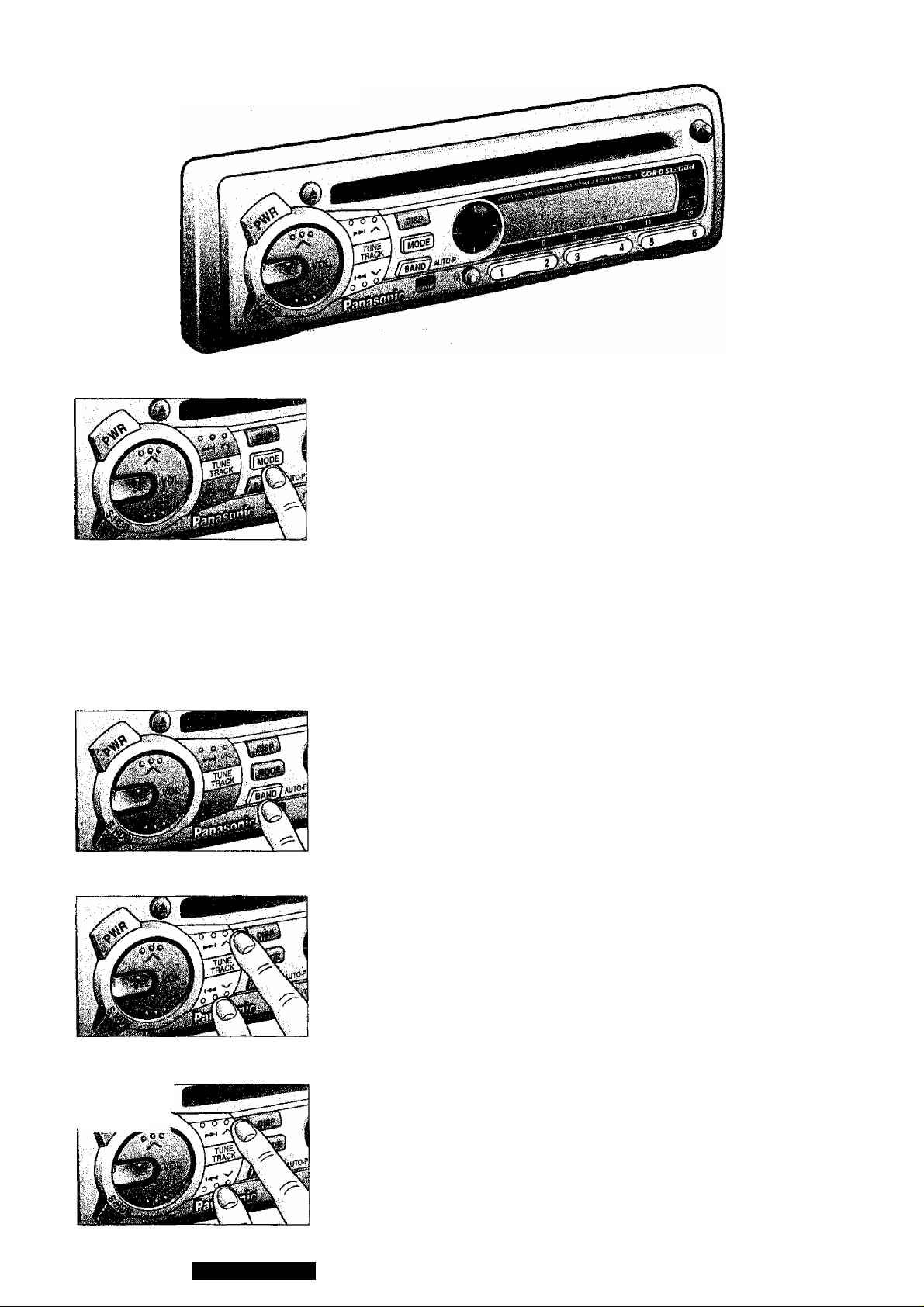
Radio Basics
To change Tuner Mode
Press MODE to switch the operation mode in the following order.
Tuner ^ CD Player ^ (CD Changer Control)
t
_________________
r fMMlm ^ tjX 1.13 mm
Selecting a Band
Press BAND to select the bands in the following order.
“ST” indicator lights if the station is broadcasting in stereo.
FM1 FM2 FM3 AM(LW/MW)
t
______________ __
S'
Manual Tuning
Press “ VTUNE” or “TUNE A” to move to a lower or higher frequency.
Press and hold “VTUNE” or “TUNEA” to move to a lower or higher
frequency rapidly.
16
Hold and
release
Seek Tuning
Press and hold "VTUNE” or “TUNEA” for more than a half second,
then release. The radio automatically stops on the next station.
CQ-DPG55LEN
Page 17
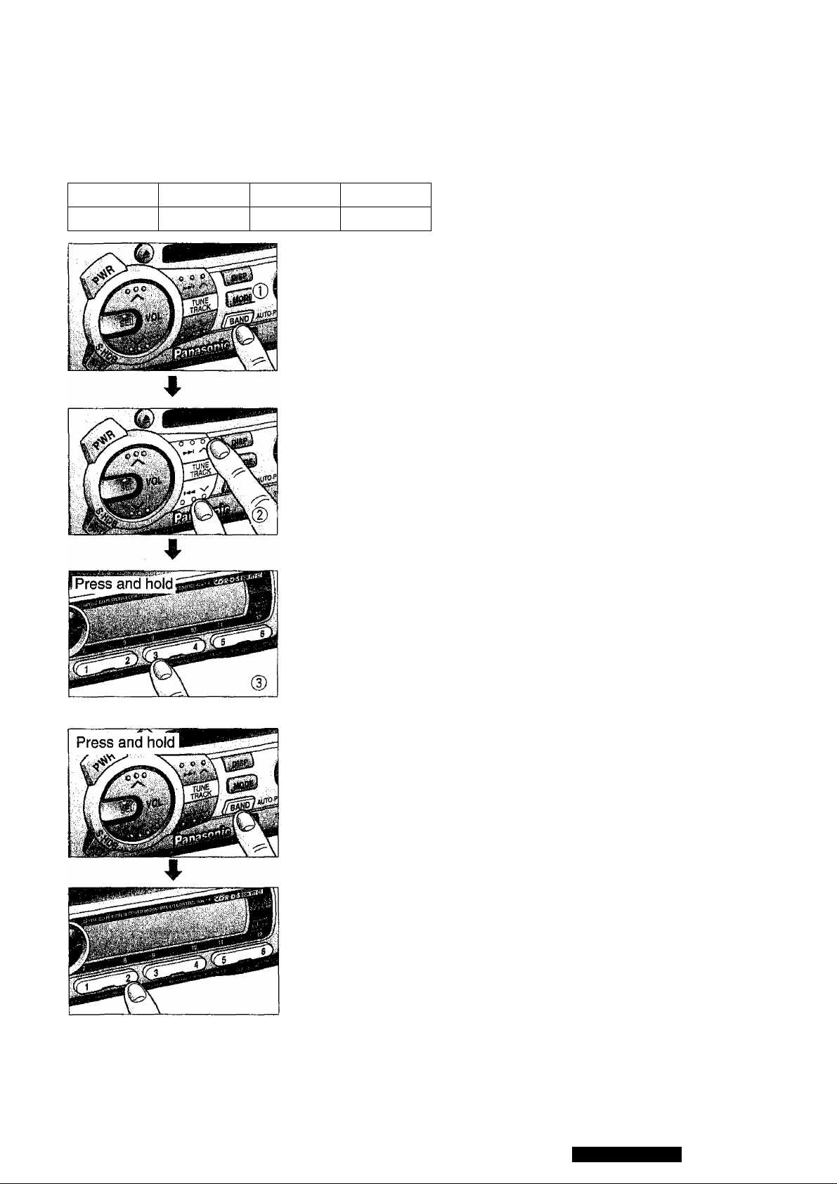
Preset Station Setting
Up to 24 stations can be preset in the station memory as follows;
FM1
6 stations
FM2
6 stations 6 stations
FM3
Manuai Station Preset
© Press BAND to select a desired band.
(2) Use manual or seek tuning to find a station that you want to program
® Press and hold one of the station selector buttons 1 through 6 for
Note: You can change the memory setting by repeating the above pro
cedure.
Tuning in a Preset Station
Press any of the buttons 1 through 6 to tune in the station preset by the
above steps ® to ©.
AM(LW/MW)
6 stations
into memory.
more than 2 seconds until the display blinks.
Repeat the process to set other stations for the FM1 to AM bands.
Preset Channel Indicator
Auto Station Preset
Select a band and press and hold BAND (AUTO • P) for more than 2
seconds.
• The six strongest available stations will be automatically set in memo
ry on preset buttons 1 through 6.
• Once set, the preset stations are sequentially scanned for 5 seconds
each.
• Press the appropriate preset button for the station you want to hear.
CAUTION: For safety reasons, do not attempt to program white driving.
CQ-DPG55LEN
17
Page 18

RDS (Radio Data System) Reception
Many FM stations are broadcasting added data compatible with RDS. This radio set offers
convenient functions using such data.
AF (Alternative Frequency)
When receiving condition becomes poor, an RDS
station with the same program will be automatically
selected.
EON (Enhanced Other Networks)
When EON data is received, the EON indicator
lights and the TA and AF functions are expanded.
TA: Traffic information from not only the station
now tuned in to but also other stations of the
same network can be received.
AF: The frequency list of the RDS stations preset
by received EON data is updated.
TA (Traffic Announcement)
When an FM station that periodically provides the latest traffic information is received, the TP indicator
lights. If TA ON is set, FM traffic information automatically interrupts tour listening to a CD, CD changer
source until it ends, then you will listen again to whatever you have been listening to.
PS (Program Service Name)
When an RDS station is received, the RDS indica
tor lights and automatically displays the name of
that station instead of the frequency. When DiSP
is pressed during PS display, the frequency is dis
played for 3 seconds, then PS display returns.
P! (Program Identification)
If a preset RDS station is poor in receiving condi
tion when it is selected, the automatic seek (PI
Seek) starts to seek the same program and tune
in to it.
PTY (Program TYpe)
Program type identification signal
REG(Reg)on)
The AF, Best Station Research, PI Seek functions will be as follows:
REG ON : The frequency changes only with the same regional program. This function Is mainly used
while driving in the same area, for example, in a city.
REG OFF: The frequency changes even with a different regional program if the station is in the same net
work. The broadcast may be different depending on the case. This function is mainly used
when driving far from one region to another.
WHAT PROVIDES EON CAPABILITIES
EON lets the radio set take advantage of RDS information much more then before. It constantly
updates the AF list of all presets, including the station currently tuned in to. So, even if you change pre
set far from home, you will be able to receive the same station at an alternative frequency, or another
station serving the same program if any. EON also keeps track of locally available TP stations for quick
reception.
Note: When you’re in “AF ON” mode, auto preset memory only works for RDS station. When in “TA
on” mode, it only works for TP stations. To make auto preset for ordinary stations, cancel AF mode and
switch to TA off in advance.
18
CQ-DPG55LEN
Page 19
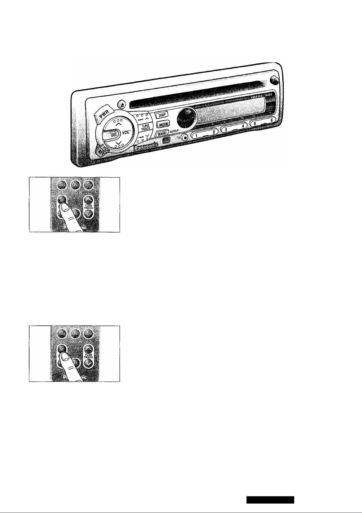
A. Basic Operation in RDS Reception (PS, AF, CT, PI)
RDS Reception
{Use the remote controller for the following operation.)
Press AF when receiving a station in the FM1, FM2 or FM3 band.
• The operating mode changes to AF ON or AF OFF, respectively.
iiai
IK RH
<Remote control operatlon>
• Select AF ON if you wish to use the AF network of an RDS station.
Best station research is activated at the same time.
• Select AF OFF if the AF network of an RDS station is not neces
sary.
dn^Biiàiia
<Remote control operatlon>
Best Station Research
If a preset RDS station is in poor condition of reception when you try to
tune in to it, the best frequency is selected from the AF list of that station.
To Change AF Mode
(Use the remote controller for the following operation.)
Press AF to chage AF ON and activate Best Station Research at the
same time, (3 seconds maximum)
IK RH W -
■n'nr"
if i f L i
Notes:
1. Default mode is AF1.
2. AF1 has a low level of AF operating sensitivity in urban areas.
Therefore, AF dose not frequently operate even of sensitivity is
temporarily lowered between skyscrapers, for examples.
3. AF2 is for suburban areas with a higher level of sensitivity than
AF1.
RH
CQ-DPG55LEN
19
Page 20
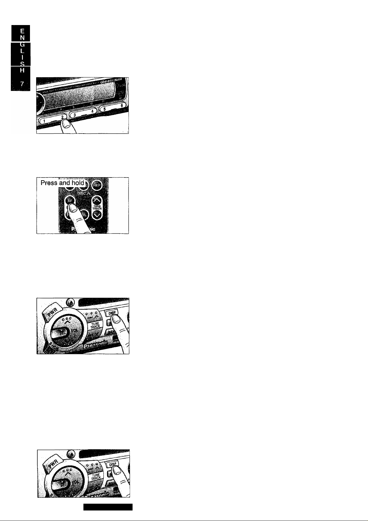
RDS (R ad io Da ta S yst em ) Rec ep ti on
For Seek Tuning, RDS Station Preset, Tuning in a RDS preset station, and Auto RDS
Station Preset, please refer to Radio Basics (Page 16 to page 17).
continued
RDS seek tuning (PI seek)
The PI seek function may be used if an RDS station selected from the
memory is poor in receiving condition. Press the preset button again
for the station now tuned in to.
SEEH;^
PI
PI Seek: If Best Station Research fails in selecting the best station,
the PI seek function operates to automatically tune in to the
same program.
Region (REG) Switching
(Use the remote controller for the following operation.)
Press and hold AF for more than 1 second in AF mode to alternately
select REG ON and REG OFF.
<Remote control operation>
ms ^ ^
Note:
If you wish to stay with the same program, keep REG ON. If you keep
REG OFF, there is a higher possibility of returning in to an AF station
in better receiving condition.
The relationship of the PI seek function with REG ON and REG OFF
is as described above.
PEG OFF
Changing Display
• Press DISP to change the display as follows.
(Frequency display continues for only 3 seconds, returning to PS
display after that.)
PS display -^1
Frequency display—
CT display
-----
•(3 seconds)
Clock Time (CT) System
The CT (24-hour) system may not properly operate in areas where
RDS CT service is not available. Once CT service is received, the CT
system keeps operating. “NO CT” is displayed in areas where no CT
service is available.
20
Clock Display
Press DISP to indicate the clock display.
CQ-DPG55LEN
Page 21
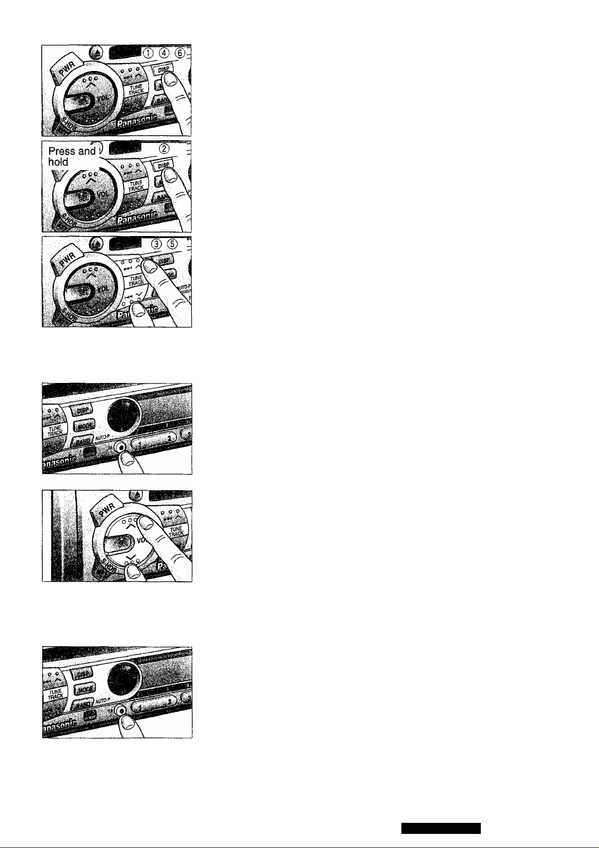
Initial Time Setting
Press BAND to change to AM mode.
© Press DISP. “NO Cr is displayed.
© Press and hold DISP again for more than 2 seconds, "hours” blinks
indicating the time setting mode is activated.
© To set hours, press “TUNE A or VTUNE”.
0 Press DISP again for minutes setting.
0 To set minutes, press TUNE A or VTUNE.
Hold “ A” or “ V” change numbers rapidly.
® When set the time, press DISP.
Notes:
• If CT display is kept on, it remains on even if PWR and ACC are tuned
off and back on again.
• In CD Changer mode, press and hold DISP for more than 2 seconds
(In FM, CD mode, press DISP) to get RDS CT-service.
B. TP Reception
Select traffic information (TA on) mode
Press TA to switch ON and keep it there when you wish to listen to traffic
information. Press TA to switch OFF when no traffic information is need
ed.
Volume Setting (Only for CD/CD C TA on mode)
Adjust the volume as desired using “VOLA” or “V VOL” while receiving
traffic announcement. (TA)
After volume for traffic announcement (TA) is set, the glifference
between normal volume and TA volume is automatically stored in the
memory (up to 5 levels) so that next traffic information will be received
at the preceding TA volume which may be higher or lower than normal
volume.
Normal volume can be changed up to 5 levels upward or downward.
If an adjusted level of volume is over 40 or less than 0, any further
change will not be made.
When receiving a station other than TP station (includ
ing EON stations)
A traffic information station is automatically searched for and the radio
automatically stops the next available TP station. EON Capabilities:
EON lets the radio take advantage of much more RDS information than
before. It constantly updates the AF lists for all switch presets far from
home, you will receive an alternative frequency for the same station, or
another station carrying the same program, when such exists. EON also
keeps track of locally available TP station.
Press TA.
CQ-DPG55LEN
21
Page 22
RDS (R ad io Da ta S yst em ) Rec ep ti on
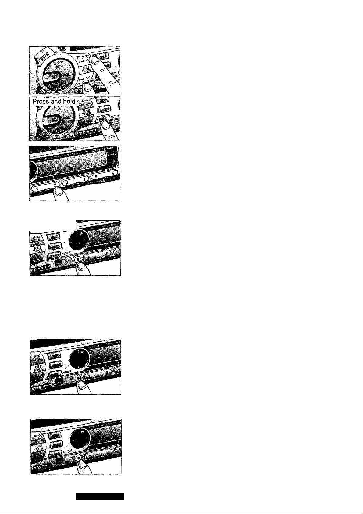
TP Seek Tuning
Press “VTUNE” or 'TUNE A” for more than a half second, then
release. The radio automatically stops on the next available TP station.
Auto TP Station Preset
Press and hold BAND (AUTO • P) for more than 2 seconds until the display
blinks in TA on. The six strongest available TP stations are automatically set
in memory on the preset button 1 through 6.
Once set, the preset stations are sequentially scanned for 5 seconds each.
Tuning in a TP station preset
Press any of the preset buttons 1 through 6 that you want to hear. And then
Best Station Research function is activated to automatically select the
strongest available frequency for the TP station (through the built-in frequen
cy) lists, if reception is weak.
33C XENT'i^
continued
jfpressan^oid
Muting TA on
Press and hold TA for more than 2 seconds to light TA on”.
Then Traffic Announcement (TA) function is activated to operate,
allowing you to listen to only Traffic Program whenever it is available.
Muting TA on canceling (Muting TA on TA on)
Press TA again.
Press “VOLA” to increase the volume level.
TP Auto Search
If receiving conditions are poor when TA is on during muting and if
there is no other alternative frequency in the same network, a traffic
announcement station in good receiving condition is automatically
searched for.
CD/CD-C TA on
Press TA during CD, CD changer mode.
TA on mode is selected, while listening to the source in that mode,
wait for Traffic Announcement to being.
(CD)
01 0 "dc‘
Information
End
22
Switching to TA off Mode
Select either one of the following steps.
• Press TA when TA is ON.
• Press and hold TA for more than 2 seconds when Muting TA is ON.
• Press TA when CD/CD-C TA is ON.
CQ-DPG55LEN
Page 23
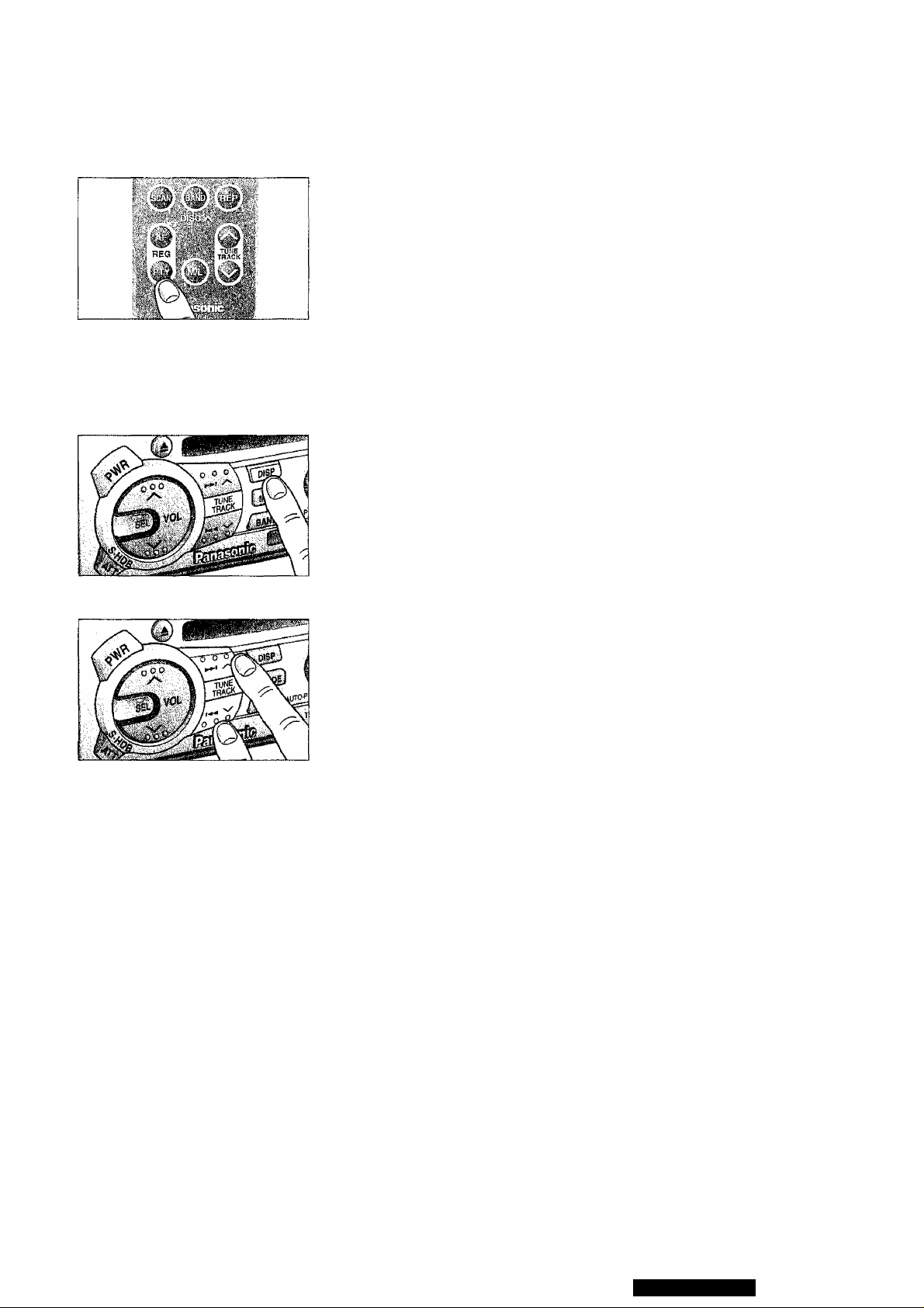
C. PTY Reception
(There are some areas where PTY service may not be available.)
Switching to PTY mode
(Use the remote controller tor the following operation.)
Press PTY to select PTY display mode, and the PTY of the broadcast
now received is displayed.
<Remote control operation>
CLR55IÌI5
"NO PTY ” is show if there is no corresponding program type.
NO
rprania
pifTlDEB
Changing PTY Display Language
Pressing DISP each time in PTY mode to alternate the language
between English and Swedish.
Press DISP
NERB
<English>
NUHETE£
<Swedish>
Program Type Selection
Press “VTUNE” or “TUNE A” to select the program type in
sequence as follows.
-SPEECH - MUSIC-NEWS-AFFAIRS-INFO-SPORT-EDUCATE-DRAMA
ROCK M - POP M - VARIED - SCIENCE - CULTURES
I
M.O.R.M - LIGHT M - CLASSICS - OTHER M - WEATHER - FINANCE
I
LEISURE - TRAVEL - PHONE IN - RELIGION - SOCIAL A - CHILDREN
I
JAZZ - COUNTRY - NATIONAL - OLDIES - FOLK M - DOCUMENT-
When the desired selection has been made, press BAND. Then auto
matic seek will start to tune into the station broadcasting the selected
program type.
Note :
Seek tuning does not operate as long as “NO PTY” is displayed.
CQ-DPG55LEN
23
Page 24
RDS (R ad io Da ta S yst em ) Rec ep ti on
TABLE of PTY CODE and program Type
Press any of the preset button 1 through 6 that you want to desire the
program type. Those buttons are already stored program types as
below. (Initial setting)
<PRESET PTY>
Preset NO.
continued
Program Type NEWS
Display
Press and hold
ifnq
ntf'“ ’
NEWS AFFAIRS
SPEECH
SPGEQI?
INFO
EDUCATE
DRAMA
CULTURES
SCIENCE
VARIED
WEATHER
FINANCE
CHILDREN
SOCIAL A
RELIGION
PHONE IN
TRAVEL
LEISURE
DOCUMENT
SPORTS
EPOPT
SPORT
POP. MUSIC
POP : n H
POPM
CLASSICS
CLP5SIC5 5
CLASSICS ROCKM
MUSIC
Aiil irrr
tiUDlL
M.O.R.M
LIGHT M
OTHER M
JAZZ
COUNTRY
NATIONAL
OLDIES
FOLKM
Program Type Preset
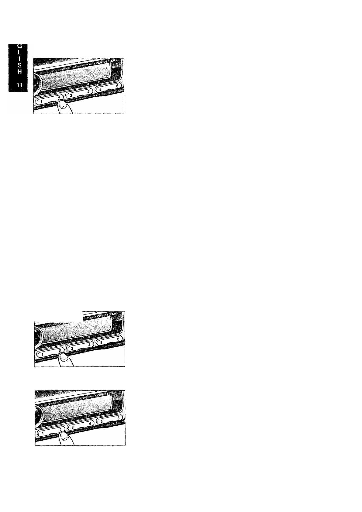
Press and hold one of the buttons 1 through 6 for more than 2 seconds
to preset the desired program type selection in that button.
24
Tuning in a PTY Preset Station
Press any of the preset buttons 1 through 6 that you want to hear.
Page 25
<Remote control operation>
n
Searching for PTY
(Use the remote controller for the following operation.)
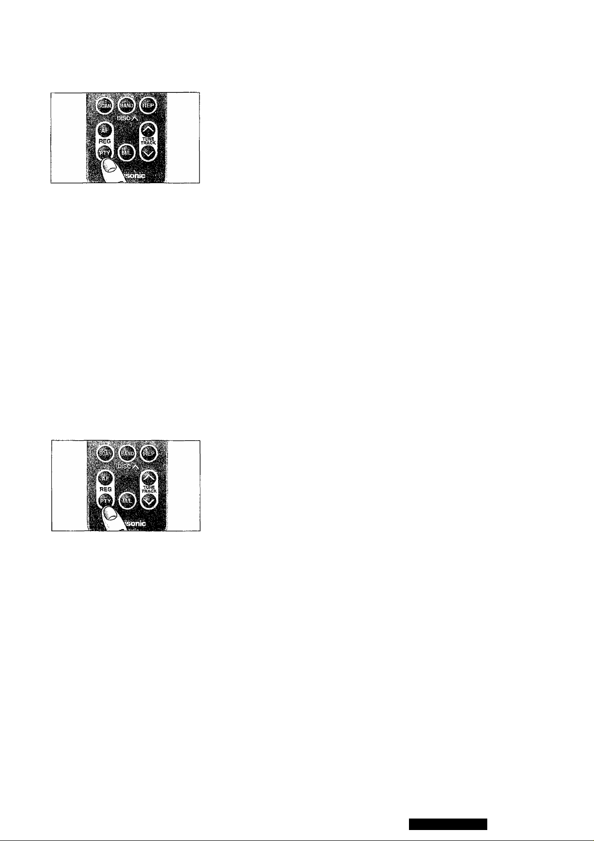
© Select the desired station from among those preset in the preset
number buttons 1 through 6. (The buttons of Main unit.) Then, the
preset PTY and that preset number are displayed for 5 seconds,
(When PTY is dispiayed, PTY may be searched for with the BAND
button after selecting PTY with “ VTUNE” or “TUNE A”.)
POP M h'
Press preset button.
© While the desired type from 6 presets is displayed, take either of the
following two steps.
A) Press the same preset button again. (The buttons of Main unit.)
B) Press BAND.
If the desired PTY station is available, it is directly received. If It is
not, “NO PTY” blinks and the radio returns to the station that was
received before the search.
Press
preset button.
Press
preset button.
<Remote control operation>
Press the same button again to cancel.
Canceling of PTY Mode
(Use the remote controller for the following operation.)
Press PTY to cancel.
The set returns to the state existing before PTY mode while the receiv
ing frequency remains unchanged.
Emergency Announcement
Reception
(Some areas are not covered by emergency announcement service.)
If an emergency announcement is broadcast during CD/CD changer
mode, the radio is automatically selected to receive the emergency
announcement. “ALARM” blinks.
CQ-DPG55LEN
25
Page 26
Compact Disc Player Basics
Mode Selection
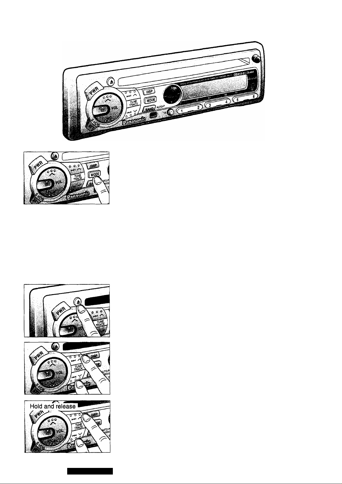
Press MODE to change into the CD player mode.
To start the CD Player
Insert the disc and playback starts automatically.
“CD LOAD” will be displayed until the disc is loaded. Play starts from
first track.
EJJ LORD D i
Note: While the disc is inserted, “CD IN ” indicator will light.
u LitJ
Stopping and Ejecting a Disc
Press “A” to stop CD piay, and the disc will quietly eject from the CD
slot. (During disc ejection, “CD EJECT’ will be displayed.)
Selecting a Track
• Press TRACK^*H” once to go to the next track.
• Press “H^^TRACK” once to play from the beginning of the track you
are listening to. Press twice to play the previous track,
• Press repeatedly to skip the desired number of tracks.
26
Searching a Track
• Press and hold “TRACK^-^I” or “H^-^TRACK” for more than a half
second to activate fast fonward or reverse through a track.
• Release ‘TRACK^^i” or “t^-^TRACK” to resume the normal CD
play.
CQ-DPG55LEN
Page 27
Selecting by Track Number H
(Direct Track access) H
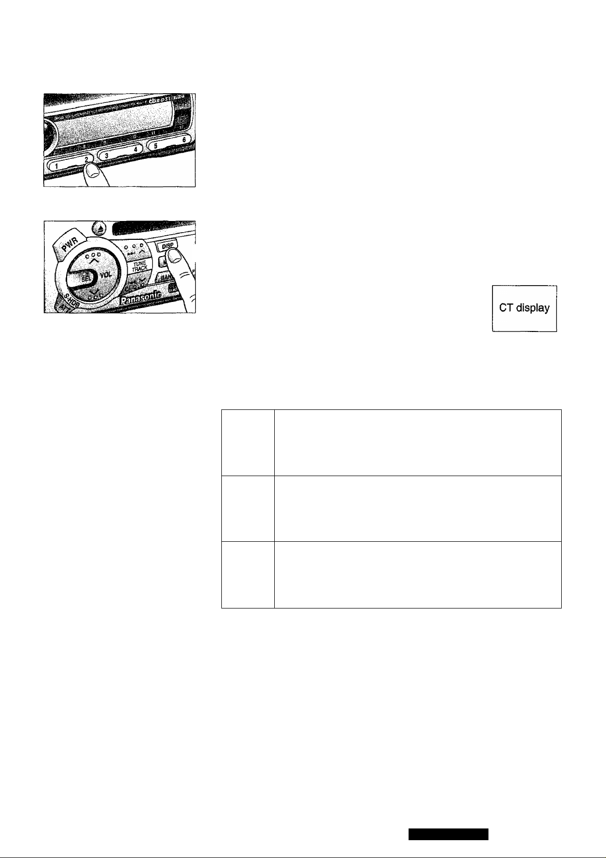
• Press a number from “V to “6” than the corresponding track will start.
• Press and hold a number from “7” to “12” (“1” to "6”) for more than
one second and the corresponding track will start.
Changing the Display
j Press DISP to switch the display in sequence as follows.
Track Number/
Track Play Time
Press DISP.
I
Error Display Messages
Displays when the compact disc is dirty or upside down.
The disc eject automatically.
f
£3
But, the disc may eject automatically, even if this error
message is not displayed.
Displays when compact disc is scratched. The disc eject
automatically.
But, the disc may eject automatically, even if this error
message is not displayed.
Displays when the compact disc stops operating for some
reason. Please turn off the car engine (ACC off) and remove
the fuse from yellow lead for 1 minute. Then reinstall the
fuse.
CQ-DPG55LEN
27
Page 28
CD Changer Basics
Note:
CD changer control functions are applicable to units with
optional CD changer unit, (sold separately)
To start the CD Changer
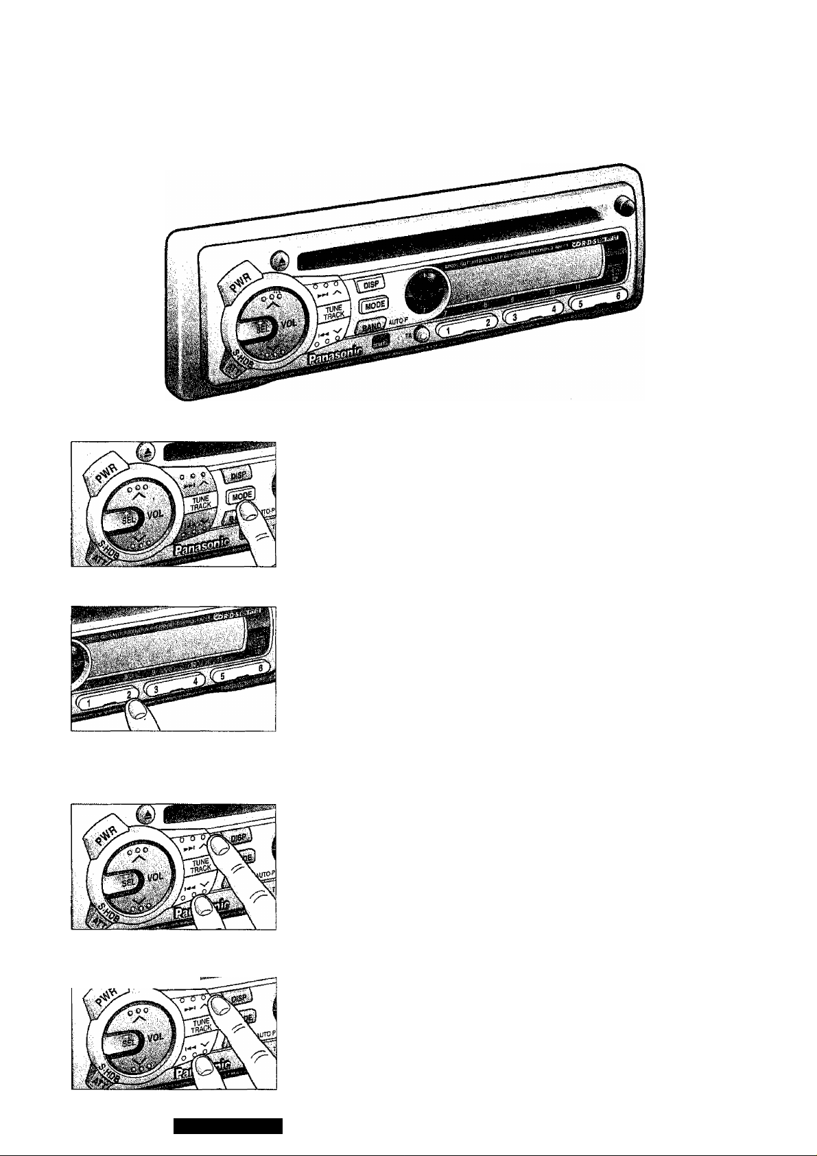
While CD changer is connected, press MODE to change into the CD
changer mode and playback starts automatically.
CMC i-0 I
Selecting a Disc
(Direct Disc access)
• Press a number from “1” to “6” than the corresponding Disc will start.
Only for CX-DP1200EN
• Press and hold a number from '7” to “12” {'T to “6”) for more than
one second and the corresponding Disc will start.
Selecting a Track
• Press TRACK ►>!” once to go to the next track.
® Press TRACK” once to play from the beginning of the current
track. Press twice to play the previous track.
• Press repeatedly to skip the desired number of tracks.
28
------------------
Hold and release
Searching a Track
• Press and hold TRACK or TRACK” for more than a half
second to activate fast forward or reverse through a track.
® Release “TRACK or TRACK” to resume the normal CD
play.
GQ-DPG55LEN
Page 29
Changing the Display
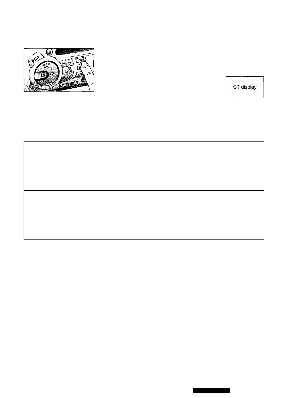
Press D!SP to switch the display in sequence as follows.
Disc/Track Number
Track Play Time
Error Display Messages
rur r 1
L i
DISC No.
Cic EE
CHd E3
Displays when the compact disc is dirty or upside down. Selects the next
available compact disc.
Displays when compact disc is scratched. Selects next available compact
disc.
Displays when the unit stops operating for some reason. Press RESET on the
CD Changer (optional).
Press and hold DISP for
more than 2 seconds.
t
Press DISP.
rur nnnn
lMl uuyy
Displays when there is no disc in the magazine.
CQ-DPG55LEN
29
Page 30
Remote Control Basics
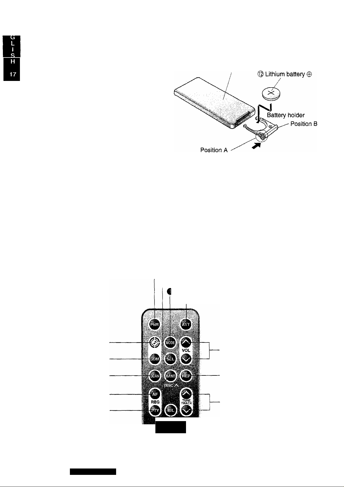
Battery Replacement: -
1, Remove the battery holder.
Pull the holder by the Position B while pushing
Position A in the direction indicated by the
arrow.
2. Replace the battery.
Set a new battery properly with (+)side up
as illustrated.
3. Insert the battery holder.
Push in the holder to the original position.
Back side
Note on Batteries:
Old batteries must immediately be removed and disposed.
Battery Information:
• Designated Battery: Panasonic Lithium Battery (CR2025)
• Battery Life: 6 months with normal use (in normal room temperature)
Caution;
Improper use of batteries may cause overheating, explosion or ignition, resulting in injury or fire.
Battery leakage may cause damage to the unit.
• Do not disassemble or short the batteries. Do not throw the batteries into the fire.
• To avoid the risk of accident, keep the batteries out of reach of children.
----------------------
Names of Main Controls:
Power Button
i Select Button
Mode Button
® ATT Button
30
O S - HDB Button
O SDM Button
@ SCAN Button
AF/REG (RDS) Button
O PTY (RDS) Button
CQ-DPG55LEN
Panasonic
: Sar-AudTp. .
^ MONO/LOCAL Button
BAND /DISC UP Button
® Volume Control Button
® REPEAT Button
0 TUNE/TRACK Up/Down Button
Page 31

Operating Procedures
General
Aim the remote controller toward the sensor of
the main unit.
Power
® PWR (Power Button)
Press PWR to switch on the power.
Press PWR again to switch off the power.
s
________________________________________
Mode Selection
О MODE (Mode Button)
Press MODE to switch the operation mode in the
following order.
Tuner ^ CD Player ^ (CD Changer Control)
___________
---------------------------------------------------------------------------------------------------------
Volume
VVOLA (Volume Control Button)
Press “A” or “V” to increase or decrease vol-
. ume level.
''---------------------------------------------------------------------
Super High Definition Bass О s * HDB Button
• Press (S • HDB) to be able to listen to
high-definition bass.
• Press the same button again to cancel.
Attenuator
Ф ATT Button
• Press ATT to decrease volume to about 1/10
of the previous level.
• Press ATT again to cancel.
-___________J'
____
Changing Audio Modes
9 SEL (Select Button)
>
Press SEL to switch the audio control mode in
the following order.
Normal Mode # VOL ^ BAS4TRE4BAL# FAD
t__________________Mr
^
^
Bass and Treble
9 VVOLA (Volume Control Button)
Press SEL to select the BASS (TREBLE) mode.
Press “VOLA” or “VVOL” to increase or
decrease the bass (treble) response.
V
_______________________________________
--------------------------------------------------------------------------------------------------- N,
Balance
ill VVOLA (Volume Control Button)
Press SEL to select the BALANCE mode. Press
“VOLA” or “VVOL” to shift the sound volume
to the right or left speakers.
'
______________________________________________________________________
Fader
® VVOLA (Volume Control Button)
Press SEL to select the FADER mode. Press
“VOL A” or “VVOL” to shift the sound volume
to the front or rear speakers.
■“ ■■ ~ -s
y
^
Sound Memory (Only for Remote Control)
Changing Sound Memory
0 SDM (SDM Button)
Press SDM to switch the sound memory in the following order.
Initial ^ SOUND 0 ■►SOUND 1 ^ SOUND 2 ^ SOUND 3
t
_______________________
Sound memory settings are as follows.
SOUND 0 (at Initial) 0 0 Center Center
SOUND 1 (On expressways: recommended)
SOUND 2 (Vocal emphasized) -6 -6
SOUND 3 (Bass emphasized) 0
Notes: Desired sound memory input:
• If SDM is pressed at SOUND 0,1, 2, or 3 after changing BAS, TRE, BAL, FAD, or S*HDB settings, the
selected condition is stored in the memory of “SOUND 0”.
• When “SOUND” is not displayed, press SDM to show current SOUND mode.
Mode change is valid only when “SOUND” is displayed.
*
BAS TRE BAL FAD S»HDB
OFF
+6 +3 Center
Center Center
+3 Center
Center
Center
OFF
OFF
ON
CQ-DPG55LEN
31
Page 32
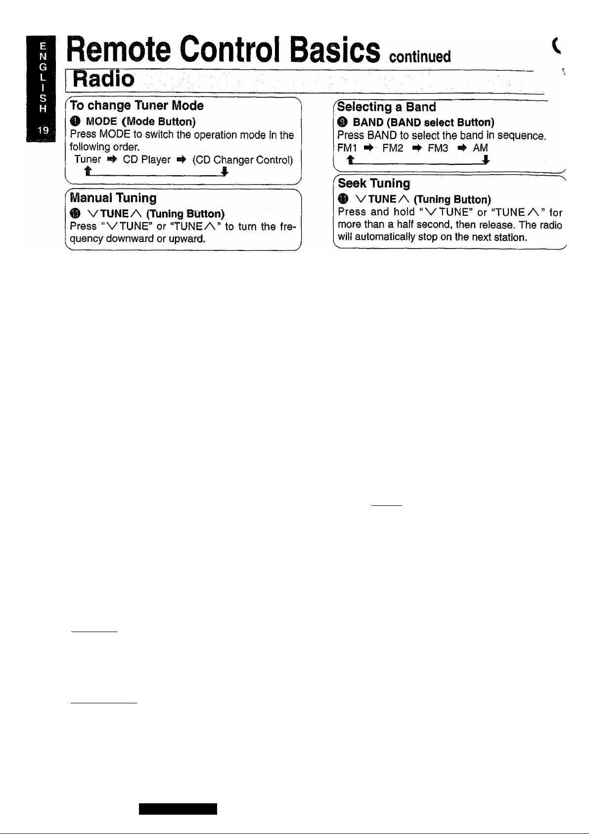
MONO/LOCAL Selection
® MONO/LOCAL Button
• Much interference is reduced during a weak FM stereo
broadcasts, when MONO is ON. (Only for FM mode)
® Searching stops automatically at a strong wave station
only when LOCAL is ON.
0 During FM broadcasts.
Press M/L to switch the mode in the following order.
MONO OFF MONO ON MONO ON
LOCAL OFF LOCAL OFF “► LOCAL ON
t
___________________________________
(2) During AM broadcasts.
Press M/L to switch on or off the LOCAL mode as
follows,
LOCAL OFF W LOCAL ON
^ MONO OFF
^ LOCAL ON
RDS (Radio pata System^ Reception
RDS Reception
^ AF (AF Button)
Press AF when receiving a station in the FM1,
FM2 or FM3 band.
• The operating mode changes to AF ON or AF
OFF, respectively.
• Select AF ON if you wish to use the AF net
work of an RDS station. Best station
research is activated at the same time.
• Select AF OFF if the AF network of an RDS
station is not necessary.
_____________________________________________________________
_________^
To Change AF Mode
O AF (AF Button)
Press AF to change AF ON and activate Best
Station Research at the same time. (3 seconds
maximum)
________________________________
Region (REG) Switching
0 AF (AF Button)
Press and hold AF(REG) for more than 1 sec
ond in AF mode to alternately select REG ON
and REG OFF._____________________________
Switching to PTY mode
© PTY (PTY Button)
Press PTY to select PTY display mode, and the PTY
of the broadcast now received is displayed.
“NO PTY ” is show if there is no corresponding pro
gram type.
Canceling of PTY Mode
O PTY (PTY Button)
Press PTY to cancel. The set returns to the state
existing before PTY mode while the receiving fre
quency remains unchanged.
— - ---- -- ^
Searching for PTY ~
• PTY (PTY Button)
© Select the desired station from among those
preset in the preset number buttons 1 through
6. (The buttons of Main unit) Then, the preset
PTY and that preset number are displayed for
5 seconds.
® While the desired type from 6 presets is dis
played, take either of the following two steps.
j
A) Press the same preset button again. (The
buttons of Main unit)
B) Press BAND.
If the desired PTY station is available, it is
directly received. If it is not, “NO PTY” blinks
and the radio returns to the station that was
received before the search.
Press the same button again to cancel.
32
CQ-DPG55LÉN
Page 33

Compact Disc Player
(When a disc is inserted, playback starts.)
To Start CD Play
O MODE (Mode Button)
Onty when a disc is inserted, press to select CD play
mode, and playback starts automatically.
Tuner CD Player “► (CD Changer Control)
t
________________________
When a disc is inserted, CD play starts automatically
regardless what mode you are being listened.
Selecting a Track
® V TRACK A (Track Select Button)
• Press “A” once to go to the next track.
• Press “V” once to play from the beginning of
the currently played track.
• Press repeatedly to skip forward or backward
through all the tracks.
^
Searching a Track
0 VTRACK A (Track Select Button)
• Press and hold "V” or “A” for more than a
half second to activate fast forward or reverse
through the track.
• Release to stop reverse or fast forward.
Repeating a Track (Only for Remote Control)
® REP (Repeat Button)
Press REP to repeat the current selection. “REP”
indicator will light.
Press REP again to cancel.
Scanning a Disc (Only for Remote Control)
@ SCAN (SCAN Button)
Press SCAN. The display will blink and the first
10 seconds of each track on the discs play in
order.
Press SCAN again to cancel.
CD Changer Control
(In connection with the CD Changer)
To Start CD Play
O MODE (Mode Button)
When connecting with the CD changer, press repeat
edly to select the mode as follows.
Tuner ^ CD Player ^ (CD Changer Control)
t
________________________
Selecting a DISC
@ DISC UP (BAND Button)
Press DISC UP to sequentially advance to the
next DISC.
Selecting a Track
0 VTRACK A (Track Select Button)
• Press “A” once to go to the next track.
• Press “V” once to play from the beginning of
the currently played track.
• Press repeatedly to skip forward or backward
through all the tracks.
*
A
^Searching a Track
(D VTRACK A (Track Select Button)
• Press and hold “V” or “A” for more than a
half second to activate fast forward or reverse
through the track.
• Release to stop reverse or fast forward.
Repeating a Track (Only for Remote Control)
0 REP (Repeat Button)
Press REP to repeat the current selection. “REP”
indicator will light.
Press REP again to cancel.
Scanning Track (Only for Remote Control)
O SCAN (SCAN Button)
Press SCAN. The display wiil blink and the first
10 seconds of each track on the discs play in
sequence.
Press SCAN again to cancel.
CQ-DPG55LEN
33
Page 34
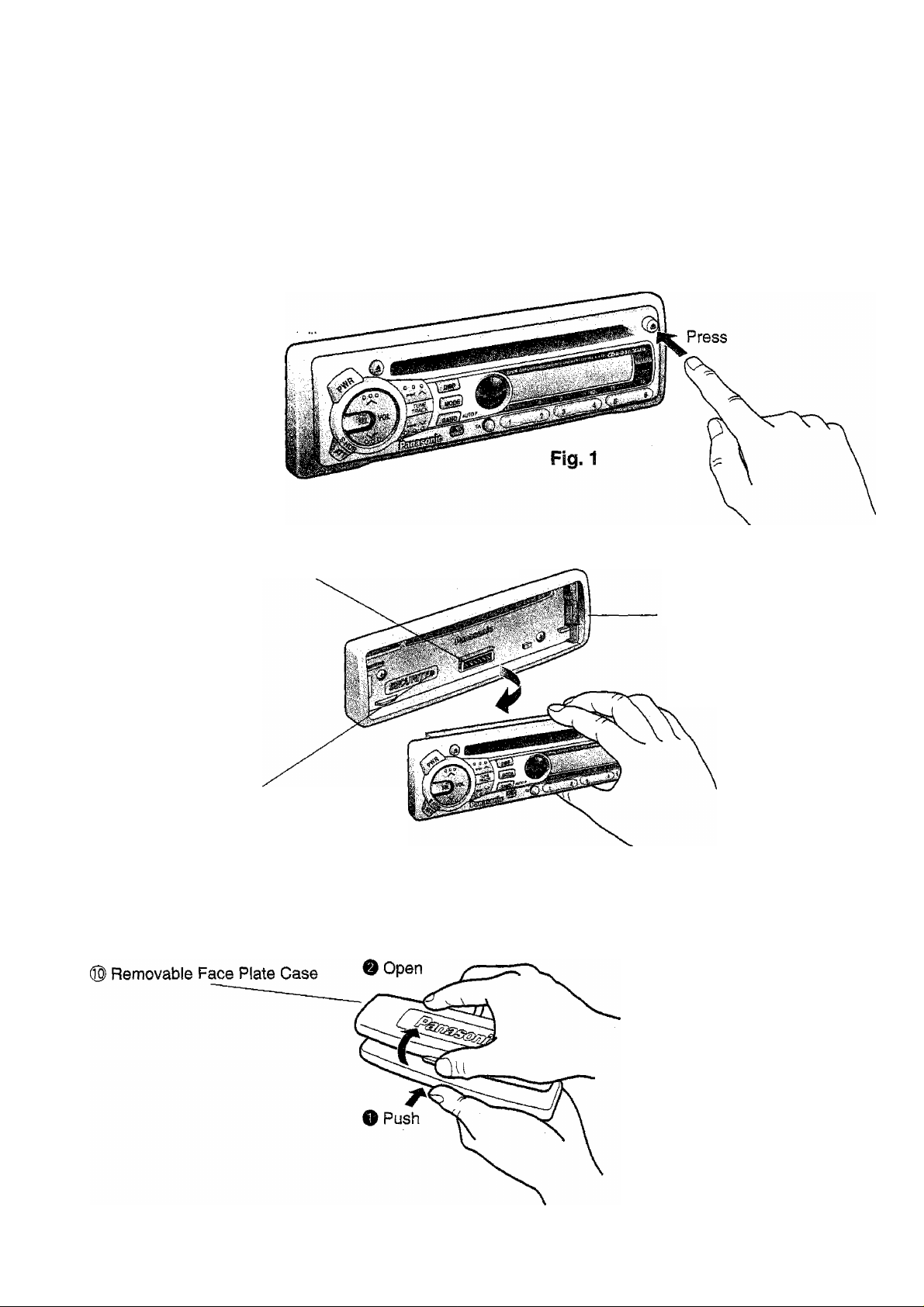
Anti-Theft System
This unit is equipped with a removable face plate. By removing this face plate, the radio becomes totally inop
erable. The security indicator will blink.
To Remove the Removable Face Plate
0 Switch off the power.
0 Press the release button The removable face plate will be released.
0 Remove the removable face plate by pulling on the right side of the unit. Place the removable face plate in
a supplied case.
Contacts
Main Unit
Fig. 2
Security Indicator
0 As shown in Fig.3, insert the removable face plate with the arrow pointing toward the removable face plate
case until you hear a “click”. Keep the removable face plate in the case. Then, you can bring the plate
safely.
34
Fig.3
Page 35
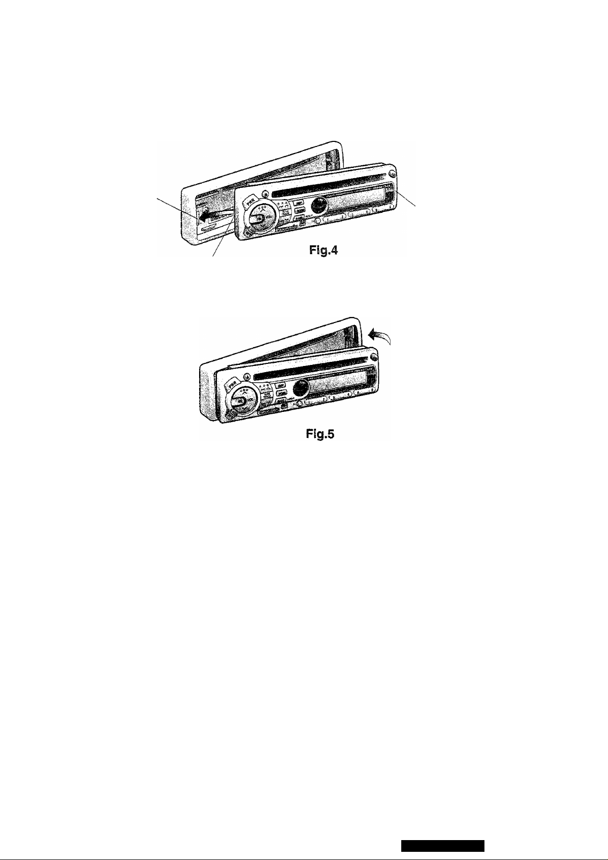
To install the Removable Face Plate
0 Slide the left side of the removable face plate in place.
Plastic Tab
Cutout
(2) Press the right end of removable face plate until “click” is heard.
Removable Face Plate
Caution:
1. Before removing the removable face plate, make sure the power is off.
2. This removable face plate is not water-proof. Do not expose it to water or excessive moisture.
3. Do not remove the removable face plate, while driving your car.
4. Do not place the removable face plate on the dashboard or nearby areas where the temperature rises
to high levels.
5. Do not touch the contacts on the removable face plate or on the main unit, since this may result in poor
electrical contacts.
6. If dirt or other foreign substances get on the contacts, wipe them with a clean, dry cloth.
CQ-DPG55LEN.
35
Page 36

Anti-Theft System continued
Warning Alarm
Caution
This car radio is equipped with an integrated Warning Alarm in order to make robbery more difficult.
But it has to be secured that the installation will be properly done so that the Warning Alarm may
work in a perfect way. Concerning the installation the following points have to be observed;
1. The supplied mounting collar has to be firmly fixed with the mounting tabs to the
dashboard.
2. The radio has to be put into the mounting collar in that way that it exactly ends with
the collar.
3. Please make sure that the technical features (impedance and power) of the speakers
installed correspond to the specifications of this car radio (see technical specifica
tions).
Only when these three points are observed during the installation, the correct function of the
“Warning Alarm” will be secured.
If the main unit is not correctly wired and installed, the system may accidentally sound the alarm.
Warning Alarm and Security Indicator
The security indicator blinks when the removable face plate is removed from the unit Furthermore, the alarm
will set off for 1 minute then reset when an attempt is made to remove the unit from the mounting collar.
Activate Warning Alarm and Security indicator
1. Press and hold SEL for more than 4 seconds when the power is ON. “ALRM ON” is displayed, and the
security indicator and Warning Alarm turn ON.
Note: The ALARM mode is inactivated when it is shipped.
2. To check whether the unit is set in the ALARM ON mode, make sure that the security indicator blinks when
the removable face plate is removed.
Display Security Indicator Warning Alarm Panel Removal Alarm
Blinks
n
L n H U
Caution;
1. Warning Alarm system may not operate if the exclusive supplied mounting collar is not used. This mount
ing collar will set off the alarm when the unit is being removed.
If the main unit is not correctly wired and installed, the system may accidentally sound the alarm.
2. When removing or installing the unit, make sure that it is in the ALARM OFF mode.
3. When the Warning Alarm is activated by mistake, or when you want to remove the unit, the Warning Alarm
and the security indicator functions can be canceled by the following steps of procedure.
• Install the removable face plate.
• Disconnect the power connector.
OFF
(Press and hold SEL for more than 4 seconds.)
OFF OFF OFF
ON
ON
Pane! Removal Alarm
This alarm sounds to warn you not to forget to remove the panel before leaving your car. This function is
activated when the security alarm is ON.
36
Page 37
Installation
Preparation
® Before Insiailation check the radio operation with antenna and speakers.
® Disconnect the cable from the negative (-) battery terminal (see caution below).
Caution:
For insiailation to cars with trip or navigational computers, ail electronic memory settings previously registered
in the computer will be lost when the battery terminal is disconnected. For this type of car, battery could not be
disconnected. Therefore, extra care should be taken to prevent short circuitting.
in-cfasti instayation
installation Opening
in-dash installation can be done if the car’s dash
board has an opening for this unit as shown in Fig.
1. The car’s dashboard should have a thickness of
4.5mm - 6mm in order to make the installation of
the unit.
■1^-
Installation Precautions
This equipment,’ if possible, should be installed by a professional installer.
■182 mmFig. 1
T
53 mm
JL
in case of difficulty, please consult your nearest authorized Panasonic Service Center.
1. This system is to be used only in a 12-voit, DC battery system (car) with negative ground.
2. Follow the eiectrica! connection on page 40 carefully. Failure to do so may result in damage to the unit.
3. Connect the power lead after other connections are made.
4. Be sure to connect the YELLOW lead to the positive terminal (+) of the battery or fuse block (BAT) terminal.
5. insulate all exposed wires to prevent short circuitting.
6. Secure all loose wires after installing the unit.
7. Please carefully read the operating and installation instructions of the respective equipment before connect
ing it to this unit.
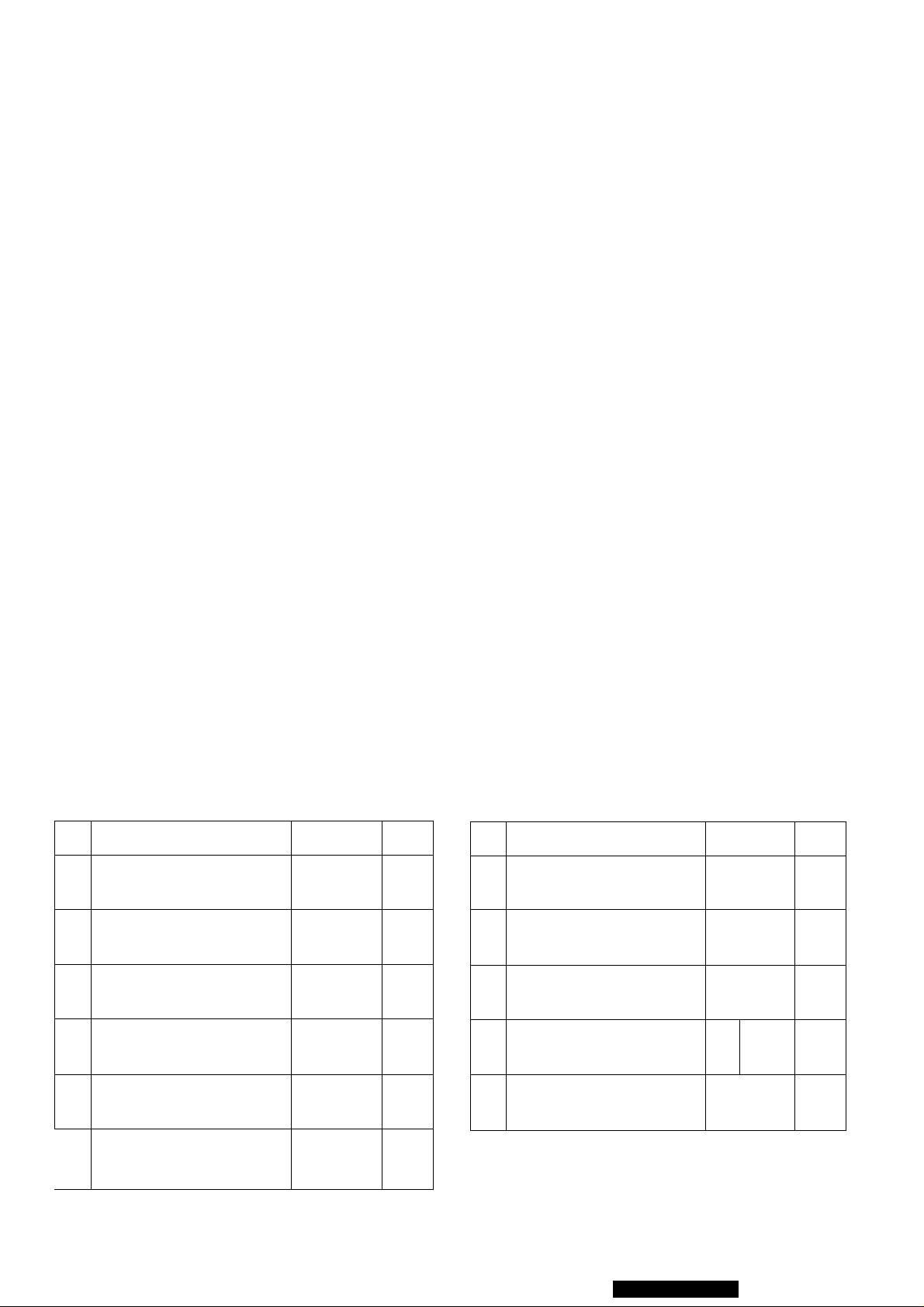
SuppSsed Hardwares
No.
Mounting Collar 1
Plain Washer (5 mm<())
Spring Washer (5 mmd)
Hex. Nut (5 inm(i>)
Item
Diagram Q’ty
2
2
©
2
No. Item
Mounting Bolt (5 mmi}))
Power Connector
Removable Face Plate
Case
Remote Control Unit
©
Diagram Q’ty
6)
999 i 1
1
1
1
Rear Support Strap
Hex. Bolt
\
(5 mm<|) X 25 mm)
(5 mmp)
1
✓
1
Lithium Battery
©
©
CQrDPGSSLEN
1
37
Page 38
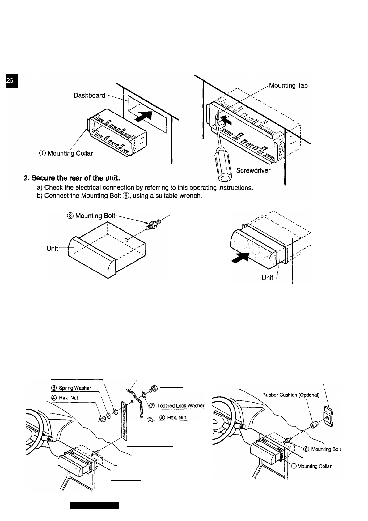
Installation
continued
installation Procedures
1. Secure the Mounting Collar ©.
Insert Mounting Collar 0 into the car's dashboard, and bend mounting tabs out with a screwdriver.
c) Insert the unit into Mounting Collar 0 and push it in until “click” Is heard.
d) Secure the rear of the unit to the car by either of the two recommended methods.
■ Using the Rear Support Strap ©
Affix one end of the Rear Support Strap ® to the rear of the unit, and the other end to the Fire Wail
of Car, or some other metallic area.
■ Using the Rubber Cushion (Optional)
(If there is an existing Rear Support Bracket on the Fire Wall of Car.)
Cover Mounting Bolt (D on the rear of the unit with Rubber Cushion (Optional), and mount it into the
existing Rear Support Bracket.
(2) Plain Washer
Rre Wall of Car
(P Hex. Bolt
Spring Washer
*\(D Plain Washer
© d) Rear Support Strap
Rear Support Bracket
(existing on the car)
C|) Mounting Bolt
38
Mounting Collar
CQ-DPG55LEN
Page 39
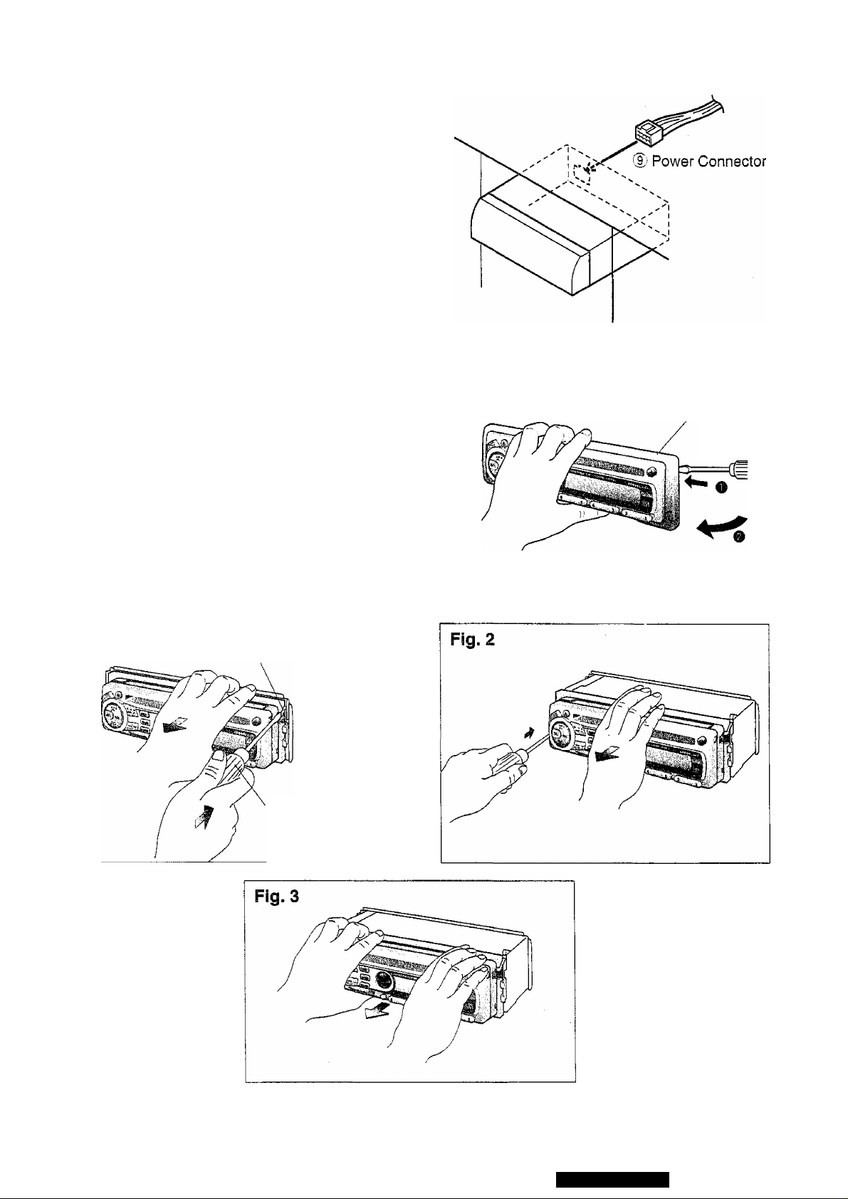
3. Plug the Power Connector d).
4. After instaSiatlon reconnect the nega
tive (—) battery terminal.
To Remove the Unit
a) Remove the trim plate with a screwdriver as shown in
the figure.
b) Pull out the unit while pushing two lock levers using
Screwdriver in the following order. {Fig. 1,2)
c) Remove the unit pulling with both hands. (Fig. 3)
Trim Plate
Screwdriver
Fig. 1
Lock Lever
Screwdriver
CQ-DPG55LEN
39
Page 40
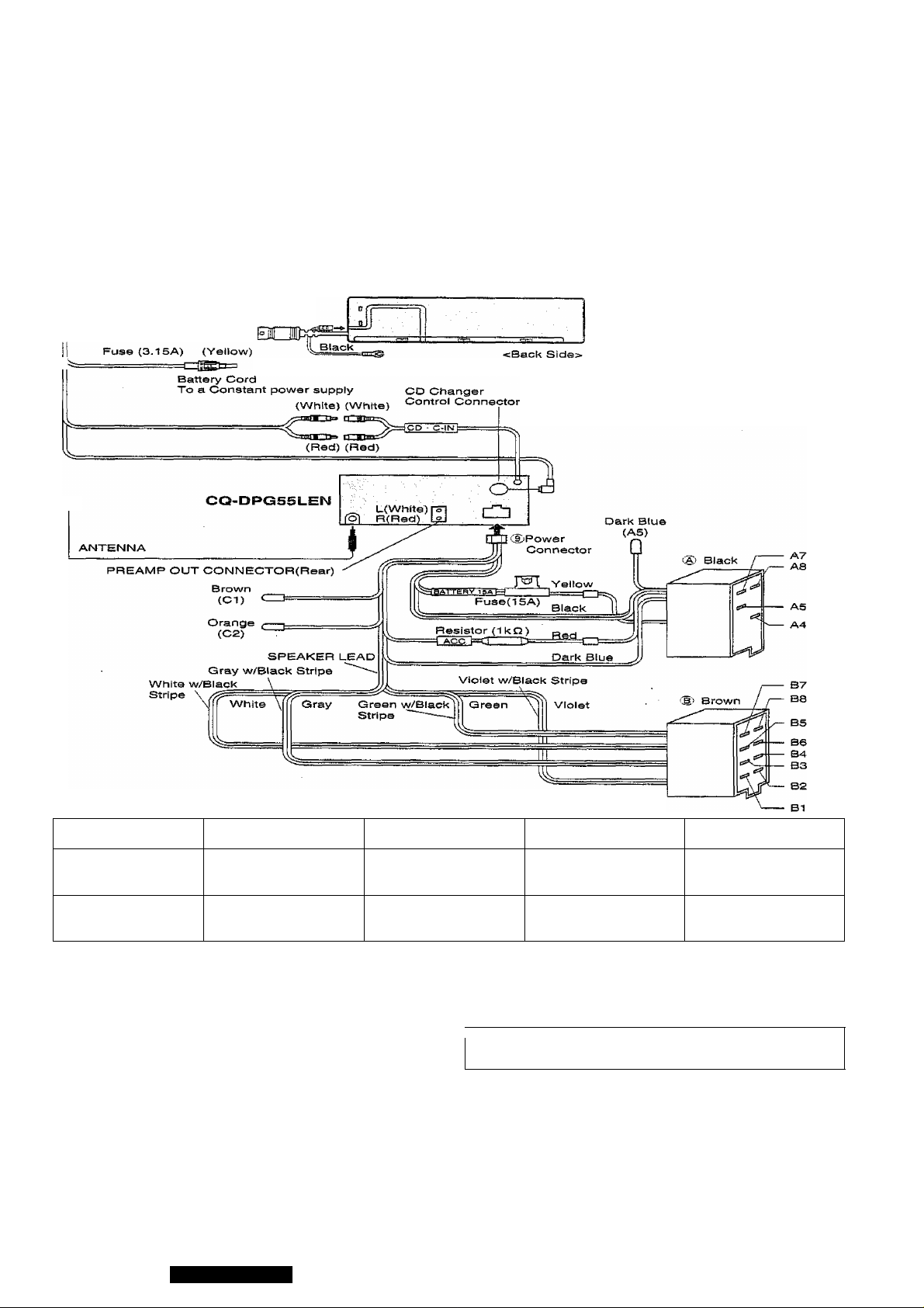
Electrical Connection
Caution:
• Confirm the note on page 4, and make connections to the connectors on car side.
• To prevent damage to the unit, be sure to follow the connection diagram below.
• Remove the covering of the leads about 5 mm long from their end before connecting, {the cords except for ISO
connector’s cords)
• Do not insert the power connector into the unit until the wiring is completed.
• Be sure to insulate any exposed wires from a possible short-circuit from the car chassis. Bundle all cables and
keep cable terminals free from touching any metai parts.
Extension Cord (DIN/BATT/RCA)
=ш[11Е^ —
CX-DP601EN
® This unit can be connected to an
optional CD changer {CX-DP600
EN/AEN or CX-DP1200EN).
For details consult your nearest
authorized Panasonic Dealer.
® For connection to a CD changer,
refer to the operating instructions
of the CD changer (CX-DP600EN/
AEN or CX-DP1200EN).
Loudspeakers (connector B)
Left Left-
Front
Rear
B5 (White)
B7 (Green)
B6 (White w/Black
B8 (Green w/Black
A4
BATTERY LEAD (To Battery of Car) (Yellow)
Connect to the ‘BAT’ terminal on the fuse block of the car.
The power should be supplied continuously to the yellow
leads regardless of the on/off position of the ignition key.
A5
MOTOR ANTENNA RELAY CONTROL LEAD (Dark Blue)
(To Motor Antenna) (Max. 500mA)
This lead is not intended for use with switch actuated power
antenna.
AMP.RELAY CONTROL POWER LEAD
This lead is for connection to Panasonic power amplifier.
A7
POWER LEAD (Red)
Connect to the “radio" power line of the car or to the “IGN"
or "ACC” terminal of the fuse block.
Stripe)
Stripe)
Right -H Right -
B3 (Gray)
B1 (Violet)
B4 (Gray w/Black
Stripe)
B2 (Violet w/Black
Stripe)
A8
GROUND LEAD (Black)
Connect to a well grounded metallic part of your car.
Cl
—
Not Used
V
____________________________
------------------------------------
C2
TELEPHONE MUTE LEAD (Orange)
(To car telephone mute line)
TELEPHONE MUTE
The telephone mute lead, if connected to the car telephone
mute line, will activate the muting circuit and the sound from
the speakers cannot be heard while the telephone conver
sation is in progress.
Note: This telephone mute lead is for connection only to the
radio mute line. Be sure to ascertain this because it will not
work with other type of output system.
\
J
40
CQ-DPG55LEN
Page 41
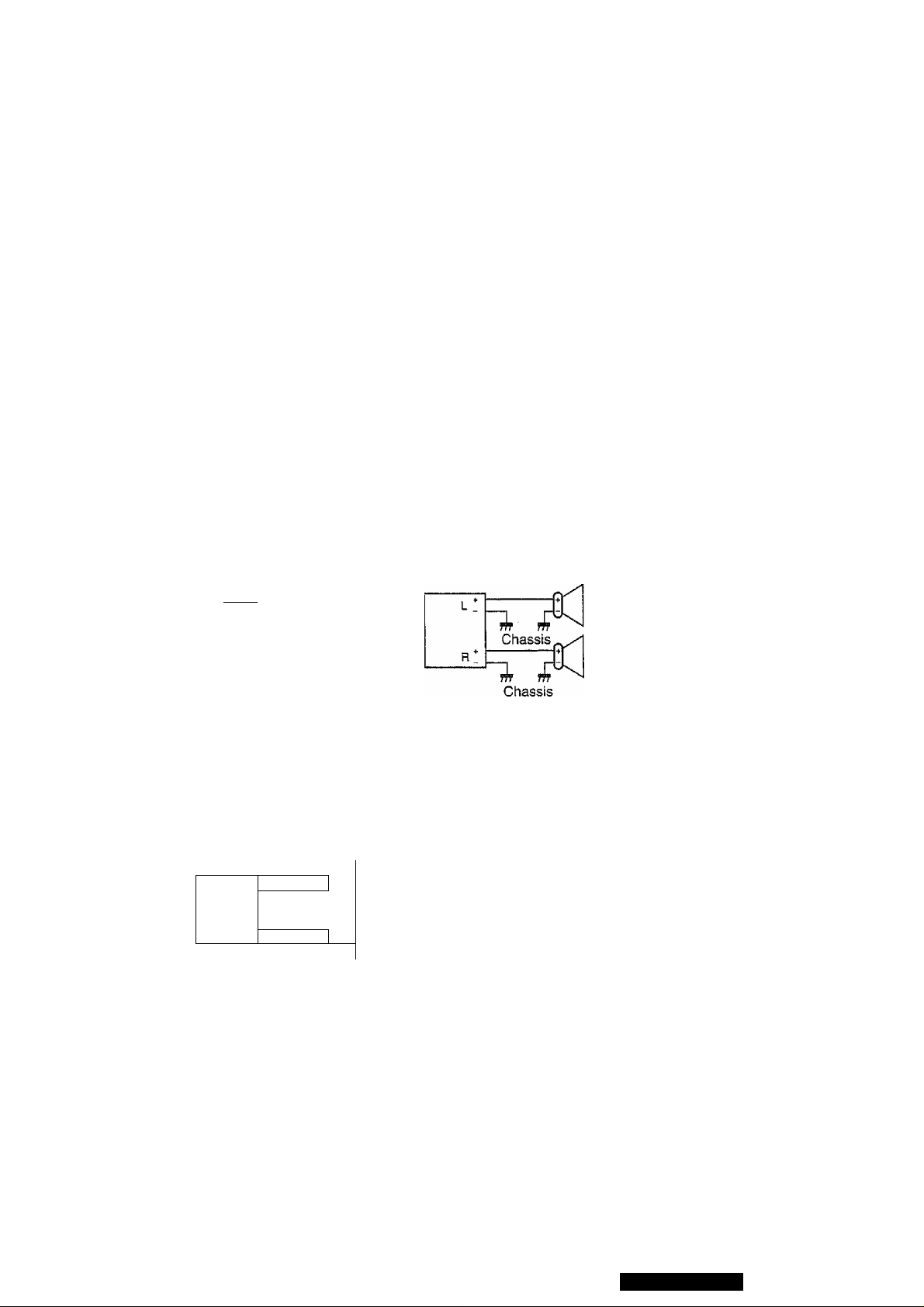
Speaker Connections
CAUTION:
1. Use ungrounded speakers only.
2. The speakers to be used with this unit should be able to handle more than 40W of audio power. If an
optional amplifier is used, the speakers should be able to handle the maximum output power of the
amplifier. Use of speakers with small input ratings can cause damage to the speakers.
3. The speaker impedance should be 4 - 8 ohms. If the impedance is too large or too small, it affects the
output and may cause damage to the speakers or this unit.
4. Do not use 3-wire type speaker system having a common earth lead. Never connect the speaker cord
to the body of the car. This unit uses the BTCL circuit, so each speaker should be connected separate
ly using parallel vinyl insulated cords.
5. The speaker cords and the power amplifier unit should be kept away (about 30cm apart) from the
antenna and antenna extension cord.
6. Follow the connection diagram below carefully. Failure to do so may cause damage to both unit and
speakers.
Unit will be damaged if speakers (Front, Rear) are not connected properly.
White
White
RIGHT
w/Biack Stripy
—
■‘Gray
w/Black Stripe
WRONG
WRONG
® Do not connect more than one speaker to one set of speaker leads.
RIGHT
White
L*
White
w/BIack Str
Grav
R*
Gray
w/Biack Stripe
I-
WRONG
R"
5
X
GQ-DPG55LEN
41
Page 42
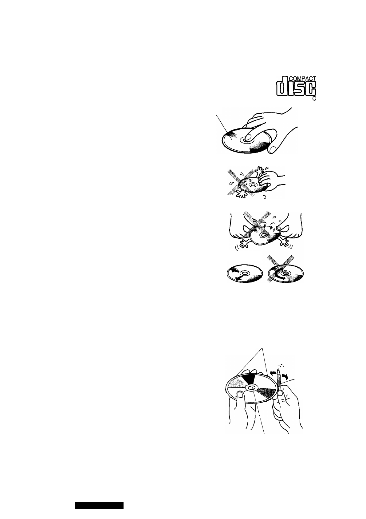
Special Notes
Notes on Compact Discs
ONLY USE DISCS CARRYING LABEL SHOWN ON THE RIGHT
• Dirt, dust, scratches and bending of disc will cause
misoperation. Handle discs with care.
• Do not place stickers or make scratches on disc.
• Do not bend discs.
• Disc should always be kept in the case when not
in use to prevent from damaging.
• Do not place discs in the following places;
1. Direct sunlight:
2. Dirty, dusty and damp areas;
3. Near car heaters;
4. Seats and dashboard.
Disc Cleaning
Use a dry soft cloth to wipe the surface, if the disc is
quite dirty use a soft cloth slightly dampened in iso
propyl (rubbing) alcohol. Never use solvents such as
benzine, thinner, conventional record cleaner, or
mopper as they may mar the surface of the disc.
DIGITAL AUDI
Label
Do not touch the
underside of the
disc.
a t-
Do not bend.
Caution for use of a new
Disc
A new disc may have rough edges on its inner and
outer perimeter. If a disc with rough edges is used,
proper setting will not be possible and the CD player
will not play the disc. Therefore, remove the rough
edges in advance by using a ball-point pen or pencil
as shown on right. To remove the rough edges, press
the side of the pen or pencil against the inner and
outer perimeter of the disc.
Wipe the disc from center to outside direction.
Rough edges
on outer perimeter
A bail-point pen
or pencil
Rough edges
on inner perimeter
42
CQ-DPG55LEN
Page 43
Fuse
Be sure to use a fuse of the specified rating (15A) when replacing a blown fuse. Fuses with higher capacity
ratings, use of any substitute, or connection without a fuse may result in a fire hazard or damage to the unit, if
the replacement fuse fails, consult your nearest authorized Panasonic Service Center.
Maintenance
To clean the exterior of this unit, use a soft cloth to wipe the surface.Do not use benzine, thinner, or any other
type of solvents.
Specifications
General
Power Supply :
Tone Controls : Bass; ± 12dB at 100Hz
Current Consumption
Maximum Power Output 40W X 4 (at 4Q)
Power Output
Speaker Impedance
Dimensions (Main unit) 178(W)x 50(H) X 150(D) mm
Weight (Main unit)
FM Stereo Radio
Frequency Range
Usable Sensitivity 6dB/|jV(S/N 30dB)
Stereo Separation
MW Radio
Frequency Range
Usable Sensitivity 28dB/|jV (S/N 20dB)
LW Radio
Frequency Range
Usable Sensitivity 32dB/|jV (S/N 20dB)
DC 12V (11V - 16V), Test Voltage 14.4V, Negative Ground
Treble; ±12dB at 10kHz
Less than 2.5A (CD mode, 0.5W 4-Speaker)
20W X 4 (DIN45 324, at 4i2)
4-sa
1.6 kg
87.5- 108MHz
35dB{at1kHz)
531 - 1,602kHz
153-279kHz
CD Player
Sampling Frequency 32 times oversampling
DA Converter MASH«1 bit/4 DAC System
Error Correction System
Pick-Up Type
Light Source
Wavelength
Frequency Response
Signal to Noise Ratio
Total Harmonic Distortion 0.01 %(1 kHz)
Wow and Flutter
Channel Separation 75 dB
Note;
Specifications and the design are subject to possible modification without notice due to improvements.
Panasonic Super Decoding Algorithm
1 -beam
Semiconductor laser
780 nm
20 Hz-20,000 Hz (±1 dB)
98 dB
Below measurable limits
CQ-DPG55LEN
43
 Loading...