

Panasonic CQ-C1110U, CQ-C1200U, CQ-C1100U, CQC1110, CQC1120 Operating Instructions Manual [en, es, fr]
...Page 1
• Please read these instructions carefully before using this product and keep this manual for future reference.
• Prière de lire ces instructions attentivement avant d’utiliser Ie produit et garder ce manuel pour l’utilisation ultérieure.
• Lea con atención estas instrucciones antes de utilizar el producto y guarde este manual para poderlo consultar en el futuro.
Removable Front Panel CD Player/Receiver
Récepteur/lecteur CD avec panneau avant amovible
Reproductor de CD/Receptor y Panel Frontal Removible
CQ-C1200U/C1120U
CQ-C1110U/C1100U
Operating Instructions
Manuel d
’instructions
Manual de instrucciones
POWER
CLOCK
CQ-C1200U
DISP
SQ
MUTE
789101112SCAN
1
2
3
46
APM
BAND
SRC
5
V
O
L
U
M
E
/
P
U
S
H
S
E
L
REP
TUNE
TRACK
D•M
(CQ-C1200U)
YFM284C404ZA TAMACO1103-0 Printed in China
Imprimé en Chine
Impreso en China
Panasonic Consumer
Electronics Company, Division
of Matsushita Electric
Corporation of America
One Panasonic Way, Secaucus,
New Jersey 07094
http://www.panasonic.com
Panasonic Sales Company.
Division of Matsushita Electric
of Puerto Rico, Inc. (“PSC”)
Ave. 65 de Infanteria, Km. 9.5
San Gabriel Industrial Park,
Carolina, Puerto Rico 00985
http://www.panasonic.com
Panasonic Canada Inc.
5770 Ambler Drive,
Mississauga, Ontario
L4W 2T3
http://www.panasonic.ca
Page 2

3
CQ-C1200U/C1120U/C1110U/C1100U
E
N
G
L
I
S
H
2
CQ-C1200U/C1120U/C1110U/C1100U
Find the model number and serial number on either the back or bottom of the unit. Please record them in the
space below and retain this booklet as a permanent record of your purchase to help with identification in case of
theft.
MODEL NUMBER
CQ-C1200U/C1120U/C1110U/C1100U
SERIAL NUMBER
DATE PURCHASED FROM
CAUTION!
THIS PRODUCT UTILIZES A CLASS ILASER.
USE OF CONTROLS OR ADJUSTMENTS OR PERFORMANCE OF PROCEDURES OTHER THAN THOSE
SPECIFIED HEREIN MAY RESULT IN HAZARDOUS
RADIATION EXPOSURE.
DO NOT OPEN COVERS AND DO NOT REPAIR
YOURSELF. REFER SERVICING TO QUALIFIED PERSONNEL.
WARNING:
TO REDUCE THE RISK OF FIRE OR ELECTRIC
SHOCK OR PRODUCT DAMAGE, DO NOT EXPOSE
THIS APPLIANCE TO RAIN, SPLASHING, DRIPPING
OR MOISTURE.
Safety Information
Consignes de sécurité
Información para su seguridad
CAUTION:
PLEASE FOLLOW THE LAWS AND REGULATIONS
OF YOUR STATE, PROVINCE OR COUNTRY FOR
INSTALLATION OF THE UNIT.
Laser products:
Wave length: 780 nm
Laser power: No hazardous radiation is emitted with
safety protection.
Il est recommandé de noter, dans l’espace prévu cidessous, les numéros de modèle et de série inscrits
soit à l’arrière soit sous le fond de l’appareil, et de
conserver ce manuel comme mémorandum de
l’achat afin de permettre l’identification de l’appareil
en cas de vol.
NUMÉRO DE MODÈLE
CQ-C1200U/C1120U
CQ-C1110U/C1100U
NUMÉRO DE SÉRIE
DATE DE L’ACHAT
VENDEUR
Busque el número del modelo y el número de serie
ya sea en la parte trasera o en el fondo de la unidad.
Sírvase anotar dichos números en el espacio siguiente, y mantenga este manual como una anotación permanente de su compra para ayudar a la
identificación en el caso de robo.
NÚMERO DEL MODELO
CQ-C1200U/C1120U
CQ-C1110U/C1100U
NÚMERO DE SERIE
FECHA DE COMPRA
NOMBRE DE LA TIENDA
ATTENTION!
CET APPAREIL EST UN PRODUIT LASER DE LA
CLASSE I.
L'UTILISATION DE COMMANDES OU RÉGLAGES
OU L'EXÉCUTION D'OPÉRATIONS AUTRES QUE
CELLES QUI SONT INDIQUÉES DANS CE DOCUMENT PEUVENT RÉSULTER EN UNE EXPOSITION À
UN RAYONNEMENT DANGEREUX.
N'OUVREZ PAS LES COUVERCLES ET N'ESSAYEZ
PAS D'EFFECTUER VOUS-MÊME DES RÉPARATIONS. ADRESSEZ-VOUS À UN PERSONNEL
QUALIFIÉ POUR TOUTE RÉPARATION.
Produits laser:
Longueur d’onde: 780 nm
Puissance du laser: Aucune radiation dangereuse
n’est émise avec la protection
de sécurité.
ATTENTION:
OBSERVEZ LES LOIS ET RÉGLEMENTS DE VOTRE
PROVINCE OU PAYS POUR L’INSTALLATION DE
L’APPAREIL.
PRECAUCIÓN:
RESPETE LAS LEYES Y REGULACIONES DE SU ESTADO, PROVINCIA O PAÍS PARA LA INSTALACIÓN DEL
APARATO.
Productos láser:
Longitud de onda: 780 nm
Potencia láser: Con protección de seguridad no se emite
radiación peligrosa.
AVERTISSEMENT:
AFIN DE LIMITER LES RISQUES D’INCENDIE OU
D’ÉLECTROCUTION OU ENCORE D’ENDOMMAGEMENT DE L’APPAREIL, N’EXPOSEZ PAS CET
APPAREIL À LA PLUIE, AUX ÉCLABOUSSURES
D’EAU OU À L’HUMIDITÉ.
ADVERTENCIA:
PARA REDUCIR EL PELIGRO DE INCENDIOS Y DE
DESCARGAS ELÉCTRICAS ASÍ COMO DE DAÑOS DEL
PRODUCTO, NO LO EXPONGA A LA LLUVIA, A
SALPICADURAS, CONDENSACIÓN DE AGUA NI
HUMEDAD.
¡PRECAUCIÓN!
ÉSTE ES UN PRODUCTO LÁSER DE LA CLASE I.
LA UTILIZACIÓN DE CONTROLES, EL HACER
AJUSTES O EL SEGUIR PROCEDIMIENTOS DISTINTOS DE LOS ESPECIFICADOS EN ESTE MANUAL PODRÍA CAUSAR UNA EXPOSICIÓN PELIGROSA A LA RADIACIÓN.
NO ABRA LAS CUBIERTAS NI HAGA REPARACIONES USTED MISMO. SOLICITE LOS TRABAJOS DE SERVICIO AL PERSONAL CALIFICADO.
The following applies only in the U.S.A.
Part 15 of the FCC Rules
FCC Warning:
Any unauthorized changes or modifications to this
equipment would void the user's authority to operate
this device.
NOTICE:
This product contains lead in some components.
Disposal of these materials may be regulated in
your community due to environmental considerations.
For disposal or recycling information please contact
your local authorities, or the Electronics Industries
Alliance: <http://www.eiae.org.>
E
S
P
A
Ñ
O
L
Lo siguiente se aplica solamente a los EE.UU.
Parte 15 de los Reglamentos FCC
Advertencia FCC:
Cualesquier cambios o modificaciones sin autorización a este equipo puede anular la autoridad del
usuario para operar este dispositivo.
AVISO:
Este producto contiene plomo en algunos componentes.
La eliminación de estos materiales puede estar reglamentado en
su comunidad debido a las consideraciones ambientales.
Para informarse acerca de la eliminación o reciclaje
comuníquese con las autoridades locales, o la Alianza de
Industrias Electrónicas: <http://www.eiae.org.>
F
R
A
N
Ç
A
I
S
Page 3

5
CQ-C1200U/C1120U/C1110U/C1100U
E
N
G
L
I
S
H
4
CQ-C1200U/C1120U/C1110U/C1100U
When Driving
Keep the volume level low enough to be aware of road
and traffic conditions.
When Washing Your Car
Do not expose the product, including the speakers and
CDs, to water or excessive moisture. This could cause
electrical shorts, fire, or other damage.
When Parked
Parking in direct sunlight can produce very high temperatures inside your car. Give the interior a chance to cool
down before switching the unit on.
Use the Proper Power Supply
This product is designed to operate with a 12 DC, negative ground battery system (the normal system in a North
American car).
Disc Mechanism
Do not insert coins or any small objects. Keep screwdrivers and other metallic objects away from the disc
mechanism and disc.
Use Authorized Servicenters
Do not attempt to disassemble or adjust this precision
product. Please refer to the Servicenter list included with
this product for service assistance.
For Installation
The product should be installed in a horizontal position
with the front end up at a convenient angle, but not more
than 30˚.
❐ Use this Product Safely
❐ Accessories
Mécanisme de disque
N’insérez pas de pièces de monnaie ou de petits objets.
Gardez les tournevis et autres objets métalliques à l’écart
du mécanisme de disque et du disque.
Réparation
Ne tentez pas de démonter ou d’ajuster l’appareil vousmême. Veuillez vous référer à la liste des centres de service fournie avec cet appareil pour contacter le service
d’assistance.
Installation
L’apppareil doit être installé en position horizontale avec
son extrémité avant inclinée vers le haut à un angle commode, mais ne dépassant pas 30˚.
Au volant
Réglez le volume à un niveau qui ne risque pas de masquer les bruits ambiants.
Lavage de la voiture
Afin de prévenir tout risque de court-circuit ou d’incendie, n’exposez pas l’équipement, y compris les hautparleurs et les disques, à l’eau ou à une humidité excessive.
Voiture stationnée
L’habitacle d’une voiture immobile exposée au soleil
toutes vitres fermées devient rapidement très chaud.
Laissez rafraîchir l’intérieur du véhicule avant d’utiliser
l’appareil.
Source d’alimentation
Cet appareil est conçu pour fonctionner sur un système
d’alimentation avec batterie de 12 V c.c. à masse
négative (système standard sur les voitures de construction nord-américaine).
❐ Précautions à prendre
❐ Accessoires
•Les caractères entre parenthèses représentent le code à spécifier d’une commande. Au cas où
l’une de ces pièces serait manquante, veuillez informer votre revendeur de ce code et du nom
de pièce.
Panasonic welcomes you to our ever growing family of electronic product owners. We know that this product will bring you many hours of enjoyment. Our reputation is built on precise electronic and mechanical
engineering, manufactured with carefully selected components and assembled by people who take pride in
their work. Once you discover the quality, reliability, and value we have built into this product, you too will
be proud to be a member of our family.
Panasonic est heureuse de vous compter parmi les utilisateurs de ses appareils électroniques. Nous pouvons vous
assurer que cet appareil vous procurera de longues heures d’agrément. Notre réputation est fondée sur une ingénierie
électronique et mécanique de haute précision, laquelle préside à la fabrication d’appareils ne comportant que des composants de choix assemblés par un personnel soucieux de la bonne réputation acquise par la qualité de son travail.
Après avoir découvert la qualité, la valeur et la fiabilité de cet appareil, vous aussi serez fier d’être un client
Panasonic.
• Operating Instructions (YFM284C404ZA) .................................................................................................................1
•
Removable face plate case (YFC054C061ZA)........................................................................................................1
• Installation Hardware .....................................................................................................................1 set (a page 28)
• Remote Control Unit (YEFX9992013B).............................................................1
• CR2025 Lithium Battery ..............................................................................1
• Warranty Card...........................................................................................................................................................1
• Manuel d’instructions (YFM284C404ZA) ..................................................................................................................1
•
Étui de rangement du panneau avant amovible (YFC054C061ZA) ..............................................................................1
• Matériel d’installation...........................................................................................................1 ensemble (a page 50)
• Télécommande (YEFX9992013B) ...............................1
• Pile au lithium CR2025 ...........................................1
• Carte de garantie.......................................................................................................................................................1
❐ Features ❐ Caractéristiques
• CD-R/CD-RW playable
• New simple-setting tone control "SQ" (Sound Quality) (a page 12)
• 4-channel high power amplifier
(50 W x 4 max. for CQ-C1200U/C1120U, 45 W x 4 max. for CQ-C1110U/C1100U)
• 2.5 V preamplifier outputs (front (excluding CQ-C1100U), rear)
• 2.5 V Sub-woofer output (only for CQ-C1200U)
• 18 FM and 6 AM presets with preset scan (a page 14)
• Anti-theft system provided by the removable faceplate (a page 19)
• Lecture des CD-R/CD-RW
•Nouvelle commande de tonalité à réglage simple "SQ" (a page 34)
• Amplificateur de puissance élevée à 4 canaux
(50 W x 4 max. pour modèles CQ-C1200U/C1120U, 45 W x 4 max. pour modèles CQ-C1110U/C1100U)
• Sortie du préamplificateur de 2,5 V (avant (sauf CQ-C1100U), arrière)
• Sortie d’
extrêmes-graves de 2,5 V (uniquement pour le CQ-C1200U)
• 18 canaux FM prédéfinis et 6 canaux AM prédéfinis avec balayage des canaux prédéfinis (a page 36)
• Système antivol prévu par un panneau avant amovible (a page 41)
F
R
A
N
Ç
A
I
S
Only for CQ-C1200U/C1120U/C1110U
Uniquement pour les modèles CQ-C1200U/C1120U/C1110U
Uniquement pour les modèles CQ-C1200U/C1120U/C1110U
Only for CQ-C1200U/C1120U/C1110U
•The numbers in parentheses indicate order numbers. In case that any of these
parts is/are missing, please inform your dealer of the number(s) and its name(s).
Page 4

7
CQ-C1200U/C1120U/C1110U/C1100U
6
CQ-C1200U/C1120U/C1110U/C1100U
Cuando conduzca
Mantenga el nivel del volumen suficientemente bajo para
estar atento a la carretera y a las condiciones del tráfico.
Cuando lave el automóvil
No exponga el equipo, incluyendo los altavoces y los
CDs, al agua o a una humedad excesiva. Esto puede
causar cortocircuitos eléctricos, incendios u otros daños.
Cuando esté estacionado
El estacionamiento a la luz solar directa puede producir
temperaturas muy altas en el interior de su vehículo.
Procure enfriar el interior antes de encender la unidad.
Uso de la alimentación apropiada
Este equipo ha sido diseñado para funcionar con un sistema de batería de 12 V CC con negativo a masa (el sistema normal en un vehículo norteamericano).
Mecanismo de disco
No inserte monedas ni ningún objeto pequeño. Mantenga
los destornilladores u otros objetos metálicos apartados
del mecanismo de disco y del disco.
Uso de los centros de servicio autorizados
No intente desmontar ni ajustar este equipo de precisión.
Consulte la lista de centros de servicio incluidos con este
producto para acudir a ellos cuando sea necesario.
Instalación
La unidad deberá instalarse en posición horizontal, con el
extremo delantero hacia arriba formando un ángulo conveniente, pero con no más de 30˚.
❐ Uso de este equipo con seguridad
❐ Accesorios
•Los números entre paréntesis indican los números de pedido. En caso de faltar alguna de estas partes, informe el número y el nombre correspondientes a su distribuidor.
Panasonic le da la bienvenida a la familia constantemente en aumento de poseedores de productos electrónicos. Nos
esforzamos en proporcionarle las ventajas de la ingeniería mecánica y electrónica de precisión, de una fabricación con
componentes cuidadosamente seleccionados, y de un montaje realizado por personas orgullosas de la reputación que
su trabajo ha cimentado para nuestra empresa. Estamos seguros de que este producto le proporcionará muchas horas
de distracción y, una vez comprobada la calidad, el valor y la fiabilidad incorporados, usted también se sentirá orgulloso
de pertenecer a nuestra familia.
• Manual de Instrucciones (YFM284C404ZA).....................................................................................................1
•
Estuche de la placa frontal extraíble (YFC054C061ZA)...............................................................................................1
• Accesorios suministrados .......................................................................................................1 juego (a página 72)
• Unidad del controlador remote (YEFX9992013B)..........................................1
• CR2025 Pila de litio ...................................................................................1
• Tarjeta de garantía.....................................................................................................................................................1
Differences among 4 models
Note: This operating instruction manual is for 4 models CQ-C1200U, CQ-C1120U, CQ-C1110U and CQ-C1100U.
All illustrations throughout this manual represent model CQ-C1200U unless otherwise specified. The following table
describes the differences among 4 models.
Remargue: Ce mode d'emploi a été rédigé pour les trois modèles suivants:
CQ-C1200U, CQ-C1120U, CQ-C1110U et
CQ-C1100U
. Toutes les illustrations qui apparaissent tout au long de ce manuel représentent le modèle
CQ-C1200U
sauf indication contraire. Le tableau ci-dessous mentionne les différences qui existent entre les 4 modèles.
Différences entre les 4 modèles
❐ Características
• Reproducción CD-R/CD-RW
• Control de tono de ajuste simple "SQ" (Sound Quality) (a página 56)
• Amplificador de alta potencia de 4 canales
(50 W x 4 máx. para CQ-C1200U/C1120U, 45 W x 4 máx. para CQ-C1110U/C1100U)
• Salida de preamplificador 2,5 V (delantero (excluyendo el modelo CQ-C1100U), trasero)
• Salida de altavoz de graves secundario 2,5 V (solamente para el modelo CQ-C1200U)
• 18 FM y 6 FM preajustes con exploración de preajuste (a página 58)
• Sistema antirrobo provisto por el panel frontal extraíble (a página 63)
Diferencia entre los 4 modelos
Nota: Este manual de instrucciones esta preparado para 4 modelo: CQ-C1200U, CQ-C1120U, CQ-C1110U y CQ-
C1100U. Todas las ilustraciones de este manual representan el modelo CQ-C1200U a menos que se indique lo con-
trario. La tabla siguiente indica las diferencias entre los 4 modelos.
Models CQ-C1200U CQ-C1120U CQ-C1110U CQ-C1100U
Maximum power output 50 W 50 W 45 W 45 W
Preamp output connector Rear/Front Rear/Front Rear/Front Rear
Remote control unit Included Included Included Not applicable
Sub-Woofer output Yes No No No
Illumination color for D·M Blue Blue Red Red
/REP/s/d
Features
Modèles CQ-C1200U CQ-C1120U CQ-C1110U CQ-C1100U
Puissance de sortie maximum 50 W 50 W 45 W 45 W
Connecteur de sortie de préamplificateur
Arrière/avant Arrière/avant Arrière/avant Arrière
Télécommande Incluse Incluse Incluse Non applicable
Sortie d’extrêmes-graves Oui Non Non Non
Couleur d’éclairage pour D·M Bleu Bleu Rouge Rouge
/REP/s/d
Caractéristiques
Modelos CQ-C1200U CQ-C1120U CQ-C1110U CQ-C1100U
Potencia de alimentación máxima
50 W 50 W 45 W 45 W
Conector de salida de preamplificador Trasero/Delantero Trasero/Delantero Trasero/Delantero
Trasero
Unidad de control remoto Incluido Incluido Incluido No es aplicable
Salida de altavoz de graves secundario
Sí No No No
Color de iluminación para D·M Azul Azul Rojo Rojo
/REP/s/d
Características
E
S
P
A
Ñ
O
L
E
N
G
L
I
S
H
F
R
A
N
Ç
A
I
S
E
S
P
A
Ñ
O
L
E
S
P
A
Ñ
O
L
Sólo para CQ-C1200U/C1120U/C1110U
Sólo para CQ-C1200U/C1120U/C1110U
Page 5

E
N
G
L
I
S
H
9
CQ-C1200U/C1120U/C1110U/C1100U
8
CQ-C1200U/C1120U/C1110U/C1100U
Contents
Safety Information (Part 15 of the fcc Rules) . . . . . . . . . . . . . . . . . . . Page 2
Use this product safely . . . . . . . . . . . . . . . . . . . . . . . . . . . . . . . . . . . . . . . 4
Accessories . . . . . . . . . . . . . . . . . . . . . . . . . . . . . . . . . . . . . . . . . . . . . . . . 14
Features . . . . . . . . . . . . . . . . . . . . . . . . . . . . . . . . . . . . . . . . . . . . . . . . . . . . 4
Differences among 4 models . . . . . . . . . . . . . . . . . . . . . . . . . . . . . . . . . . . . 7
Recommended optional systems. . . . . . . . . . . . . . . . . . . . . . . . . . . . . . . . . 8
❒ Power and Sound Controls. . . . . . . . . . . . . . . . . . . . . . . . . . . . . . . . . . 12
Power, volume, mute, display change, SQ (sound quality), audio mode
(bass/treble/balance/fader/sub woofer)
❒ Clock Setting . . . . . . . . . . . . . . . . . . . . . . . . . . . . . . . . . . . . . . . . . . . . 13
Initial time, time reset
❒ Radio . . . . . . . . . . . . . . . . . . . . . . . . . . . . . . . . . . . . . . . . . . . . . . . . . . 14
Radio mode, band, manual tuning, seek tuning, direct memory, preset
station setting, preset station calling, display change
❒ CD Player . . . . . . . . . . . . . . . . . . . . . . . . . . . . . . . . . . . . . . . . . . . . . . . 16
Disc insert and playback, stop and disc eject, listening to a CD, CD player
mode, display change, pause, track selection, track search, direct track
selection, repeat play, random play, scan play
❒ Remote Control Unit. . . . . . . . . . . . . . . . . . . . . . . . . . . . . . . . . . . . . . . 18
Battery installation, battery notes, control reference guide
❒ Anti-Theft System. . . . . . . . . . . . . . . . . . . . . . . . . . . . . . . . . . . . . . . . . 19
Remove the removable face plate, place the removable face plate into
case, install removable face plate
❒ Tr oubleshooting . . . . . . . . . . . . . . . . . . . . . . . . . . . . . . . . . . . . . . . . . . 20
Preliminary steps, if you suspect something wrong, troubleshooting tips,
error display messages, product servicing, replace the fuse
❒ Maintenance. . . . . . . . . . . . . . . . . . . . . . . . . . . . . . . . . . . . . . . . . . . . . 24
Care of the unit, notes on discs, notes on CD-Rs/RWs
❒ Installation . . . . . . . . . . . . . . . . . . . . . . . . . . . . . . . . . . . . . . . . . . . . . . 25
Overview, required tools, dashboard specifications, identify all leads,
connect all leads, final installation, final checks, preparation, dashboard
installation, installation hardware
❒ Electrical Connections . . . . . . . . . . . . . . . . . . . . . . . . . . . . . . . . . . . . . 30
❒ To Remove the Unit . . . . . . . . . . . . . . . . . . . . . . . . . . . . . . . . . . . . . . . 32
❒ Specifications. . . . . . . . . . . . . . . . . . . . . . . . . . . . . . . . . . . . . . . . . . . . 33
Only for CQ-C1200U/C1120U/C1110U
Recommended optional systems
❒ How to build the optimal audio system for you ...
It is the shortcut for getting the best quality sound to use the Panasonic audio component system.
For details, please contact your local dealer or nearest Panasonic servicenter.
• External Amplifiers (option)/Amplificateurs externes (en option)/
Amplificadores externos (opcional)
CY-M7052, CY-M9054
• Mobile Speaker Systems (option)/Haut-parleurs mobiles (en option)/
Sistemas de altavoces móviles (opcional)
Front/Avant/Delantero: CJ-RC103, CJ-RC133, CJ-RC163
Rear/Arrière/Trasero: EAK-A46, CJ-A572
Sub-woofer/H-parleur d’extrêmes-graves/Altavoz de graves secundario:
CJ-HD253, CJ-HD303, CJ-SW38
Chaînes optionnelles recommandées
❒ Constitution de la chaîne haute-fidélité la plus efficace
C’est la solution la plus facile pour obtenir le son de la meilleure qualité d’utiliser la chaîne composante
haute-fidélité de Panasonic. En ce qui concerne les détails, prenez contact avec votre concessionnaire local
ou le centre de service après-vente de Panasonic le plus proche.
Sistemas opcionales recomendados
❒ Cómo construir el sistema de audio más efectivo para Ud ...
Es el camino más corto para conseguir la mejor calidad de sonido el uso del sistema de componentes de
audio Panasonic. Para los detalles, comuníquese con su concesionario local o centro de servicio Panasonic
más cercano a su domicilio.
F
R
A
N
Ç
A
I
S
E
S
P
A
Ñ
O
L
F
R
A
N
Ç
A
I
S
E
N
G
L
I
S
H
Page 6

11
CQ-C1200U/C1120U/C1110U/C1100U
10
CQ-C1200U/C1120U/C1110U/C1100U
Índice
Información para su seguridad (Parte 15 de los Reglamentos FCC). . . . . . . Página13
Uso de este equipo con seguridad . . . . . . . . . . . . . . . . . . . . . . . . . . . . . . . . . . . . . 16
Accesorios. . . . . . . . . . . . . . . . . . . . . . . . . . . . . . . . . . . . . . . . . . . . . . . . . . . . . . . . 16
Características. . . . . . . . . . . . . . . . . . . . . . . . . . . . . . . . . . . . . . . . . . . . . . . . . . . . . . 6
Diferencia entre los 4 modelos . . . . . . . . . . . . . . . . . . . . . . . . . . . . . . . . . . . . . . . . . 7
Sistemas opcionales recomendados . . . . . . . . . . . . . . . . . . . . . . . . . . . . . . . . . . . . . 8
❒ Controles de alimentación y sonido . . . . . . . . . . . . . . . . . . . . . . . . . . . . . . . . . 56
Alimentación, volumen, silenciamiento, cambio de pantalla, SQ (
sound quality),
modo de audio (graves/agudos/balance derecho-izquierdo/balance delanterotrasero/altavoz de subgraves)
❒ Ajuste del reloj. . . . . . . . . . . . . . . . . . . . . . . . . . . . . . . . . . . . . . . . . . . . . . . . 57
Hora inicial, reajuste de hora
❒ Radio . . . . . . . . . . . . . . . . . . . . . . . . . . . . . . . . . . . . . . . . . . . . . . . . . . . . . . . . . 58
Modo de la radio, banda, sintonización manual, sintonización de búsqueda,
memoria directa, ajuste de emisoras presintonizadas, llamada de emisoras
presintonizadas, cambio de pantalla
❒ Reproductor de CD . . . . . . . . . . . . . . . . . . . . . . . . . . . . . . . . . . . . . . . . . . . . . . 60
Inserción y reproducción del disco, parada y explusión del disco, para escuchar un
CD, Modo de reproducción de CD, cambio de pantalla, pausa, selección de pista,
selección directa de pista, búsqueda de pista, repetición de reproducción,
reproducción aleatoria, reproducción por exploración
❒ Preparación del controlador remoto . . . . . . . . . . . . . . . . . . . . . . . . . . . . . . . . 62
Sustitución de la pila, notas sobre la pila, guía de referencia de control
❒ Sistema antirrobo . . . . . . . . . . . . . . . . . . . . . . . . . . . . . . . . . . . . . . . . . . . . . . . 63
Vuelva a ajustar el panel delantero,
coloque la placa frontal extraíble en la caja, instale la
placa frontal extraíble
❒ Solución de problemas . . . . . . . . . . . . . . . . . . . . . . . . . . . . . . . . . . . . . . . . . . . 64
Pasos preliminares, si cree que hay algo que no funciona bien, consejos para
localizar y solucionar averías, mensajes de visualización de error, servico técnico del
producto, reemplazo del fusible
❒ Mantenimiento . . . . . . . . . . . . . . . . . . . . . . . . . . . . . . . . . . . . . . . . . . . . . . . . . 68
Cuidado del aparato, notas sobre los discos, notas sobre discos CD-R/RW
❒ Guía de instalación . . . . . . . . . . . . . . . . . . . . . . . . . . . . . . . . . . . . . . . . . . . . . . 69
Perspectiva general, herramientas necesarias, especificaciones del salpicadero, identificación
de todos los conductores, conexión de todos los conductores, instalación final,
comprobaciones finales, preparación, Instalación en el tablero de instrumentos, accesorios
suministrados
❒ Conexiones eléctricas. . . . . . . . . . . . . . . . . . . . . . . . . . . . . . . . . . . . . . . . . . . . 74
❒ Para extraer el aparato. . . . . . . . . . . . . . . . . . . . . . . . . . . . . . . . . . . . . . . . . . . 76
❒ Especificaciones . . . . . . . . . . . . . . . . . . . . . . . . . . . . . . . . . . . . . . . . . . . . . . . . 77
Sólo para CQ-C1200U/C1120U/C1110U
Table des matières
Consignes de sécurité . . . . . . . . . . . . . . . . . . . . . . . . . . . . . . . . . . . . . . . . . . . Page13
Précautions à prendre . . . . . . . . . . . . . . . . . . . . . . . . . . . . . . . . . . . . . . . . . . . . . . . 15
Accessoires. . . . . . . . . . . . . . . . . . . . . . . . . . . . . . . . . . . . . . . . . . . . . . . . . . . . . . . 15
Caractéristiques. . . . . . . . . . . . . . . . . . . . . . . . . . . . . . . . . . . . . . . . . . . . . . . . . . . . . 5
Différences entre les 4 modèles . . . . . . . . . . . . . . . . . . . . . . . . . . . . . . . . . . . . . . . . 7
Chaînes optionnelles recommandées . . . . . . . . . . . . . . . . . . . . . . . . . . . . . . . . . . . . 8
❒ Commandes d’alimentation et de son . . . . . . . . . . . . . . . . . . . . . . . . . . . . . . . 34
Alimentation, volume, coupure du son, SQ, changement d’affichage, mode audio
(graves/aigus/balance/équilibre/extrêmes-graves)
❒ Réglage de l'horloge . . . . . . . . . . . . . . . . . . . . . . . . . . . . . . . . . . . . . . . . . . . . 35
Heure initiale, pour ajuster l’heure à nouveau
❒ Radio . . . . . . . . . . . . . . . . . . . . . . . . . . . . . . . . . . . . . . . . . . . . . . . . . . . . . . . . . 36
Mode radio, bande, syntonisation manuelle, syntonisation par recherche, mémoire
directe, réglage des stations présyntonisées, appel de station présyntonisée,
changement d’affichage
❒ Lecteur CD. . . . . . . . . . . . . . . . . . . . . . . . . . . . . . . . . . . . . . . . . . . . . . . . . . . . . 38
Insertion de disque et lecture, arrêt et éjection de disque, écoute d'un disque CD, mode de
lecteur de CD, changement d'affichage, pause, sélection de plages, sélection directe de
plages, lecture répétée, lecture aléatoire, lecture des débuts de plage
❒ Préparatifs de la télécommande . . . . . . . . . . . . . . . . . . . . . . . . . . . . . . . . . . . 40
Installation de la pile, remarques sur la pile, guide des commandes
❒ Système antivol . . . . . . . . . . . . . . . . . . . . . . . . . . . . . . . . . . . . . . . . . . . . . . . . 41
Retrait du panneau avant amovible, mise en place du panneau avant amovible
dans l’étui, installation du panneau avant amovible
❒ En cas de difficulté . . . . . . . . . . . . . . . . . . . . . . . . . . . . . . . . . . . . . . . . . . . . . . 42
Étapes préliminaires, lorsqu’on soupçonne que quelque chose est défectueux, guide de dépannage,
messages d’erreur affichés, service après-vente de l’appareil, remplacement d’un fusible
❒ Entretien . . . . . . . . . . . . . . . . . . . . . . . . . . . . . . . . . . . . . . . . . . . . . . . . . . . . . . 46
Entretien de l'appareil, remarques relatives aux disques, remarques relatives aux
CD-R/RW
❒ Guide d’installation . . . . . . . . . . . . . . . . . . . . . . . . . . . . . . . . . . . . . . . . . . . . . 47
Généralités, outils requis, dégagement requis dans le tableau de bord, identifiez
tous les fils et câbles, raccordez tous les fils, installation finale, vérifications
finales, préparation, installation sur le tableau de bord, matériel d’installation
❒ Branchements électriques . . . . . . . . . . . . . . . . . . . . . . . . . . . . . . . . . . . . . . . . 52
❒ Comment retirer l’appareil . . . . . . . . . . . . . . . . . . . . . . . . . . . . . . . . . . . . . . . . 54
❒ Données techniques . . . . . . . . . . . . . . . . . . . . . . . . . . . . . . . . . . . . . . . . . . . . . 55
Uniquement pour les modèles CQ-C1200U/C1120U/C1110U
F
R
A
N
Ç
A
I
S
E
S
P
A
Ñ
O
L
Page 7
POWER
CLOCK
CQ-C1200U
DISP
SQ
MUTE
789101112SCAN
1
2
3
46
APM
BA
N
D
SRC
5
V
O
L
U
M
E
/
P
U
S
H
S
E
L
REP
TUNE
TRACK
D•M
POWER
CLOCK
CQ-C1200U
DISP
SQ
MUTE
789101112SCAN
1
2
3
46
APM
BAND
SRC
5
V
O
L
U
M
E
/
P
U
S
H
S
E
L
REP
TUNE
TRACK
D•M
1
E
N
G
L
I
S
H
13
CQ-C1200U/C1120U/C1110U/C1100U
1
E
N
G
L
I
S
H
2
12
CQ-C1200U/C1120U/C1110U/C1100U
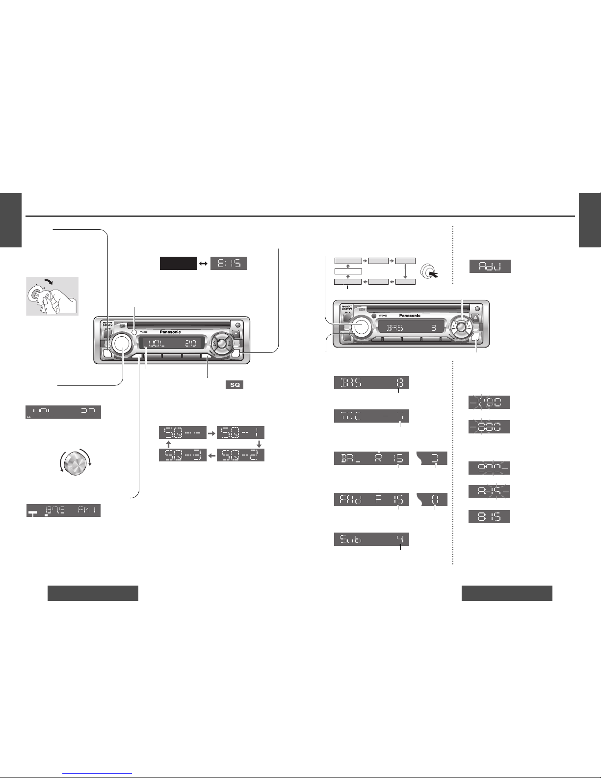
Hours
w
Press and hold [DISP] (clock) for more than 2
seconds.
e Press [k TUNE] or [l TUNE].
Minutes
r
Press [DISP] (clock).
t Press [k TUNE] or [l TUNE].
y Press [DISP] (clock).
Note: Press and hold [k TUNE] or [l TUNE] to
change numbers rapidly.
Audio Mode
(Bass/Treble/Balance/Fader/Sub Woofer)
Regular mode
Volume
Bass Treble
BalanceSub Woofer
Fader
Note: If no operation takes place for more than 5 sec-
onds in audio mode (2 seconds in volume mode), the
display returns to the regular mode.
Bass:
Adjustable range: –12 to +12 (by 2 dB step)
Treble:
Adjustable range: –12 to +12 (by 2 dB step)
Balance:
R (right speaker) or L (left speaker)
Fader:
F (front speaker) or R (rear speaker)
Push [SEL] to select the audio mode.
q
Clock Setting
The 12-hour system is used for the clock.
(Hours blink.)
(Hours set.)
(Minutes blink.)
(Minutes set.)
(End.)
Initial Time
q Press [DISP] (clock).
"AdJ" is displayed when the clock is not
adjusted.
Time Reset
Press and hold [DISP] (clock) for more than
2 seconds to activate the time setting mode to
reset the time. Then, repeat steps e to y.
[DISP] (clock)
[k TUNE], [l TUNE] (Hours, minutes)
Adjustable range: 1 to 15 (by 1 step) Balance center
Adjustable range: 1 to 15 (by 1 step) Fader center
(Only for CQ-C1200U)
Sub Woofer:
Adjustable range (level): MUTE (0) to 7
(Only for CQ-C1200U)
Push
Turn [VOLUME] clockwise or counterclockwise
to change each level.
w
default: 0 dB
default: 0 dB
(default)
(default)
default: 4
D
ISP
SQ
MUTE
SRC
Power and Sound Controls
Mute
Press [MUTE] to mute the sound completely.
lights
Press [MUTE] again to cancel.
Volume
Turn the knob clockwise to increase volume,
and counterclockwise to decrease volume.
Volume level (0 to 40)
(default: 18)
SQ (Sound Quality)
SQ is a function that can call up various sound types at
the touch of button in accordance with your listening
music type.
Press [SQ] to select a sound type as follows:
(default)
SQ -- (default) flat frequency response:
does not emphasize.
SQ - 1 (ROCK) speedy and heavy sound:
exaggerates bass and treble.
SQ - 2 (POP) wide-ranged and deep sound:
slightly emphasizes bass and treble.
SQ - 3 (VOCAL) clear sound:
emphasizes middle tone and
slightly emphasizes treble.
Power
Turn the key in the ignition until
the accessory indicator lights.
Power on: Press [SRC] (POWER).
Power off: Press [SRC](POWER)
again and hold.
ACC
ON
MUTE
ST
Display Change
Press [DISP] (display) to switch to the clock display.
Note: "AdJ" is displayed when the clock is not adjusted.
(
➡ page 13)
When the power is off:
No display Clock display
Remote control sensor (➡ page 18)*
(only for CQ-C1200U/C1120U/C1110U)
Up
Down
SQ indicator
Notes:
• If no operation takes place for more than 2 seconds in the SQ mode, the display returns to the regular mode.
•
Settings of SQ, bass/treble are influenced one another. If the influence mentioned above causes distortion to audio signal,
readjust bass/treble or volume (➡ page 13).
• CQ-C1100U has no remote control function.*
Page 8
3
E
N
G
L
I
S
H
4
E
N
G
L
I
S
H
1514
CQ-C1200U/C1120U/C1110U/C1100U CQ-C1200U/C1120U/C1110U/C1100U
POWER
CLOCK
CQ-C1200U
DISP
SQ
MUTE
789101112SCAN
1
2
3
46
APM
BAND
SRC
5
V
O
L
U
M
E
/
P
U
S
H
S
E
L
REP
TUNE
TRACK
D•M
D
ISP
1234
BA
N
D
65
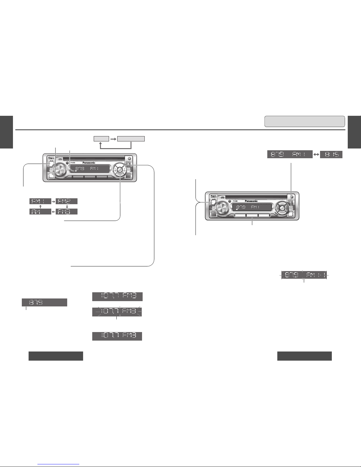
Caution: To ensure safety, never attempt to preset stations while you are driving.
Manual Preset Memory
Use manual or seek tuning to find a station.
(➡ page 14)
Press and hold one of the preset buttons from
[1] to [6] until the display blinks once.
Band
Press [BAND] to select a desired band.
(➡ page 14)
q
Auto Preset Memory (APM)
w
Preset Station Calling
Press the corresponding preset button from
[1] to [6] to tune in a preset station.
Press and hold [BAND] (APM: auto preset memory) for more than 2 seconds.
• The 6 stations with good reception will be automatically saved in the memory under preset buttons
from [1] to [6].
• Once set, the preset stations are sequentially scanned for 5 seconds each.
Preset buttons from [1] to [6]
Up to 6 stations each can be saved in the FM1,
FM2, FM3 and AM preset station memories.
Preset Station Setting
Note: Existing saved stations are overwritten with
new stations after following this procedure.
Display Change
Press [DISP] (display) to switch to the clock display.
Frequency Clock display
blinks once
ST
POWER
CLOCK
CQ-C1200U
DISP
SQ
MUTE
789101112SCAN
1
2
3
46
APM
BA
N
D
SRC
5
V
O
L
U
M
E
/
P
U
S
H
S
E
L
REP
TUNE
TRACK
D•M
ST
Radio
Manual Tuning
[l TUNE]: Higher frequency
[k TUNE]: Lower frequency
Radio
CD player
Seek Tuning
Press and hold ...
[l TUNE]: Higher frequency
[k TUNE]: Lower frequency
Tuning will automatically stop when the signals of the next
broadcast station are received.
Band
Press [BAND] to change the band.
Direct Memory(D·M)
Your favorite FM/AM radio station can be memorized in the [D
·
M] button and you can call back the radio station just by
pressing the button whatever the current sound source is, even if the power is off.
Press [D·M]. (Press again to cancel)
¡
The direct memoried station is received.
l
ights
Default: FM 87.9 MHz
e
R
elease
[D·M] button
. Then, new station will be
overwritten on existing saved station.
Press and hold [D·M] until the
Frequency display blinks.
blinks
Select the station in Radio mode (a above)
Recalling the Direct Memory
Memorize
D-M
Radio Mode
Press [SRC] (source) to change
to the radio mode.
D-M
D-M
FM Stereo indicator
Page 9
POWER
CLOCK
CQ-C1200U
D
ISP
SQ
MUTE
789101112SCAN
1
2
3
46
APM
BA
N
D
SRC
5
V
O
L
U
M
E
/
P
U
S
H
S
E
L
REP
TUNE
TRACK
D•M
5
E
N
G
L
I
S
H
6
E
N
G
L
I
S
H
1716
CQ-C1200U/C1120U/C1110U/C1100U CQ-C1200U/C1120U/C1110U/C1100U
1234 65
789101112
TRACK
DISC
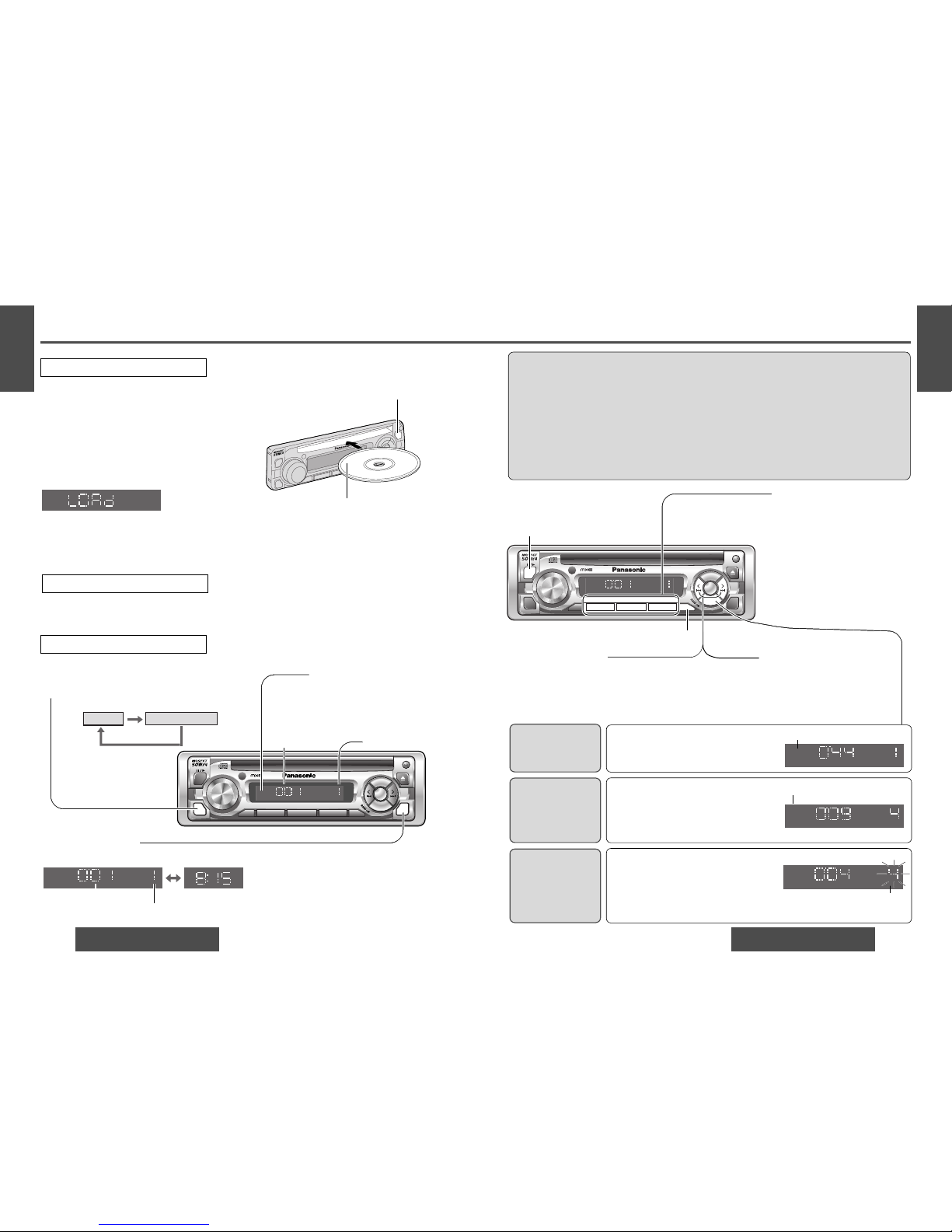
Track Selection
Press [d TRACK]: Advance to the next track.
Press [s TRACK]: Back to the beginning of the current track.
Back to the previous track. (Press twice.)
Cautions:
• Only 5" (12 cm) CD, CD-DA data recorded CD-R and CD-RW discs are available for this unit.
• This unit does not support CD text display.
• This unit does not support MP3 and WMA disc playback.
• Refer to page 24 about notes on CD-Rs/RWs.
• This unit is not designed for any 3" (8 cm) disc.
• If you insert an 3" (8 cm) disc and can not eject it, turn ACC of your car off once and turn it on again, then
press [u] (eject).
• Do not use irregularly shaped discs.
• Do not use discs that have a seal or label attached.
• Do not insert foreign matter into the disc slot.
Random play
Direct Track Selection
•Press a track number button from
[1] to [6].
The corresponding track starts
playing.
•Press and hold a track number but-
ton from [7] to [12] ([1] to [6]) for
more than 1 second.
The corresponding track starts
playing.
•Press and hold [REP] (RANDOM) for
more than 2 seconds.
All the tracks are played in random order.
•Press and hold [REP] (RANDOM) again
to cancel.
Scan play
C
Repeat play
•Press [REP].
The current track is repeated.
•Press [REP] again to cancel.
TRACK
R
DISC
5
TRACK
DISC
TRACK
REP
DISC
Scan Play
C
R 5 : Random indicator
blinks.
REP: Repeat indicator
Pause (y /5)
Press [BAND] (y /5)
to pause.
Press [BAND] (y /5)
again to resume
the playback.
Track Search
Press and hold ...
[d TRACK]: Fast forward
[s TRACK]: Fast reverse
Release to resume the regular play.
•Press and hold [SQ] (SCAN), for more than
2 seconds.
The first 10 seconds of each track on the
disc are played in sequence.
•Press and hold [SQ] (SCAN) again to
cancel.
POWER
CLOCK
CQ-C1200U
DISP
SQ
MUTE
789101112SCAN
1
2
3
46
APM
BAND
SRC
5
V
O
L
U
M
E
/
P
U
S
H
S
E
L
REP
TUNE
TRACK
D•M
D
I
SP
SRC
CD Player
Display Change
Press [DISP] (display) to switch to the clock display.
Radio
CD player
TRACK
DISC
CD Player Mode
Press [SRC] (source) to change to the CD play mode.
Playback will start automatically when a disc is loaded.
TRACK
DISC
Track playing time
track number
Clock display
Listening to a CD
Press [u] (eject) to stop CD play and eject the disc.
During disc ejection, “EJ” (eject) will be displayed.
Disc Insert and Playback
Stop and Disc Eject
Disc insert
Playback will start automatically after the player
recognized the loaded disc as an ordinary music
CD. (When a CD-R or CD-RW which has CD-DA
formatted data as the same as an ordinary music
CD is loaded, this player recognizes it as an ordinary music CD.)
“LOAd” will be displayed until the disc is loaded.
Notes:
• Do not insert a disc when “DISC” indicator
lights.
• The power will be turned on automatically when a
disc is loaded.
<CD player display>
Track playing time
Track number
<Disc indicator>
• lights when the disc is loaded.
• Do not insert a disc when “DISC”
indicator lights.
Label side
u (eject)
Page 10
7
E
N
G
L
I
S
H
8
E
N
G
L
I
S
H
1918
CQ-C1200U/C1120U/C1110U/C1100U CQ-C1200U/C1120U/C1110U/C1100U
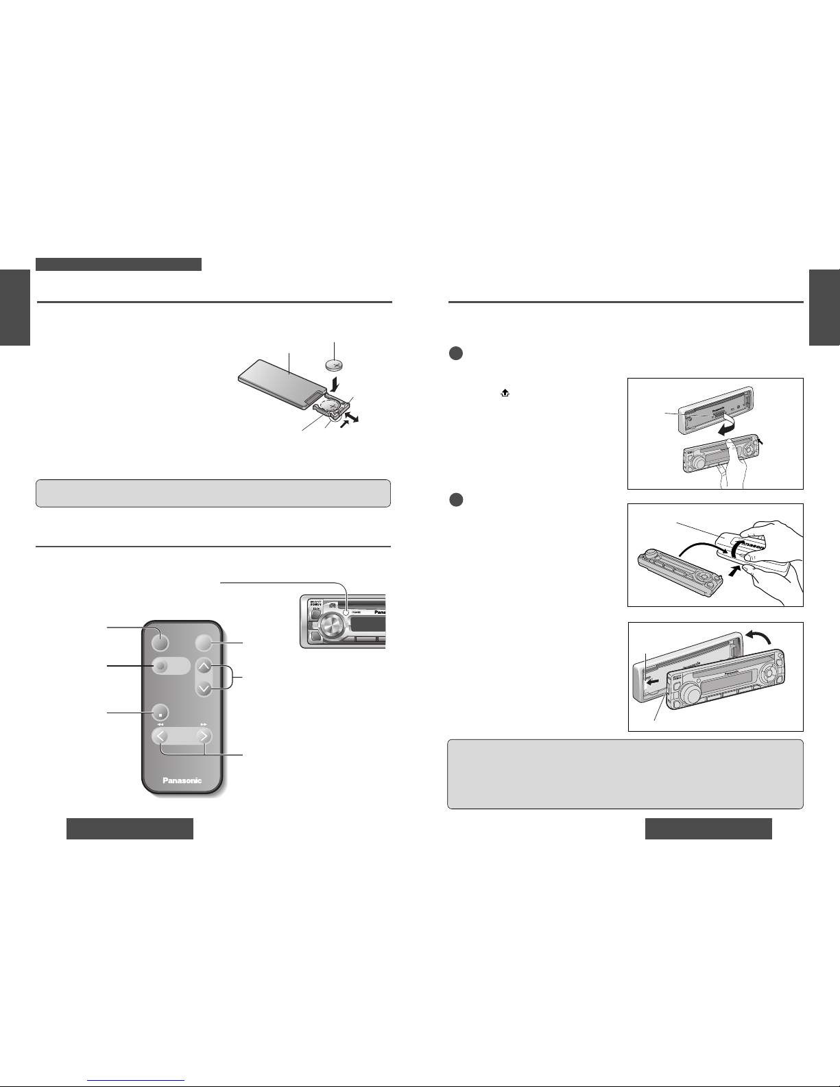
Anti-Theft System
Install Removable Face
Plate
q Slide the left side of the removable face
plate in place.
w Press the right end of the removable
face plate until “click
” is heard.
Cautions:
• This face plate is not waterproof. Do not expose it to water or excessive moisture.
• Do not remove the face plate while driving your car.
• Do not place the face plate on the dashboard or nearby areas where the temperature rises to high level.
• Do not touch the contacts on the face plate or the main unit, since this may result in poor electrical contacts.
• If dirt or other foreign substances get on the contacts, wipe them off with a clean and dry cloth.
This unit is equipped with a removable face plate. Removing this face plate makes the radio totally inoperable.
Place the Removable
Face Plate into Case
Gently press the bottom of the case and
open the cover. Place the face plate into
the case and take it with you when you
leave the car.
w
q
Removable face plate case
Tab
Cutout
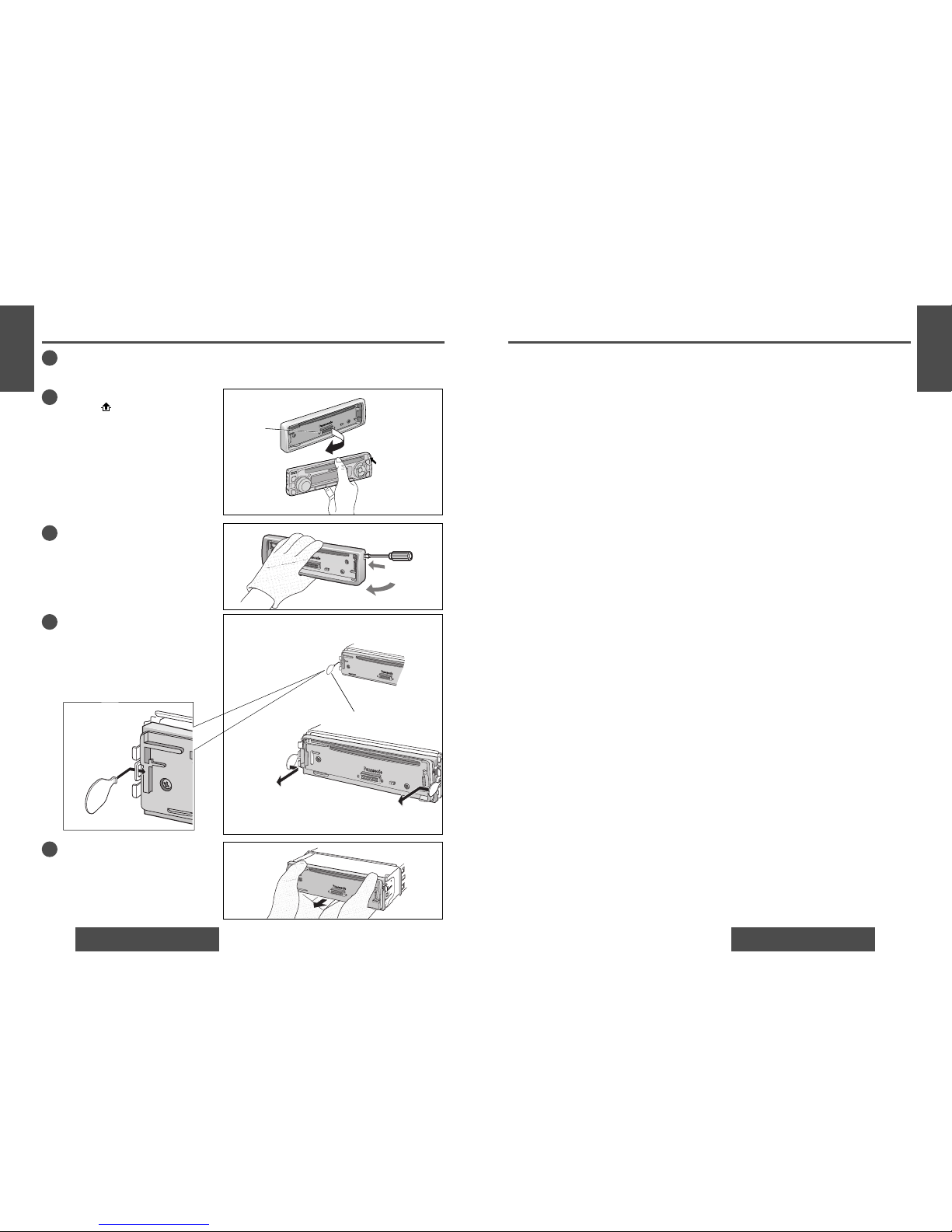
1
Remove the removable face plate
Switch off the power of the unit.
Remove the removable face plate.
q Press []. The removable face plate will
be opened.
w Push the face plate to either the right or
left.
e Pull it out toward you.
Contact
q Press
w
2
POWER
MUTE
789
1
2
3
APM
BAND
SRC
V
O
L
U
M
E
/
P
U
S
H
S
E
L
[PWR]
(Power)
(➡ page 12)
[MODE]
(Mode (source))
(➡ pages 14, 16)
Remote Control Unit
Battery Installation
Remove the battery holder.
Pull the battery holder by the position B while pushing position A in the direction indicated by the arrow.
Install the battery on the battery holder.
Place a battery in the holder with its “+
” side facing
up as shown in the figure.
Insert the battery holder.
Push the battery holder back into its original position.
Battery Notes
Remove and dispose of an old battery immediately.
Battery Information:
• Battery type: Panasonic lithium battery (CR2025)
• Battery life: Approximately 6 months with normal use (at room temperature)
Back side
Lithium battery
Battery holder Position A
Position B
• Do not disassemble or short the battery. Do not throw a battery into a fire.
• Keep batteries away from children to avoid the risk of accidents.
• Be careful to observe proper local disposal rules when you dispose of batteries.
Control Reference Guide
Buttons of the remote control function in the same way as the controls on the main unit of the reference page.
Point the remote control unit at the main unit’s sensor.
[MUTE]
(Mute)
(➡ page 12)
[VOL] [j] [i]
(Volume )
(➡ page 12)
[
TUNE][TRACK
][k] [l] [ ][ ]
(Tune/track selection/track search)
(➡ page 14, 17)
Caution: Improper use of batteries may cause overheating, an explosion or ignition, resulting in injury or a
fire. Battery leakage may damage the unit.
PWR
MODE
PRG
TUNE
TRACK
Car Audio
BAND/DISC UP
VOL
MUTE
(ATT)
Only for CQ-C1200U/C1120U/C1110U
[BAND]
(Band) (Pause)
(➡ page 14, 17)
Note: CQ-C1100U has no remote control function.
Page 11
9
E
N
G
L
I
S
H
10
E
N
G
L
I
S
H
2120
CQ-C1200U/C1120U/C1110U/C1100U CQ-C1200U/C1120U/C1110U/C1100U
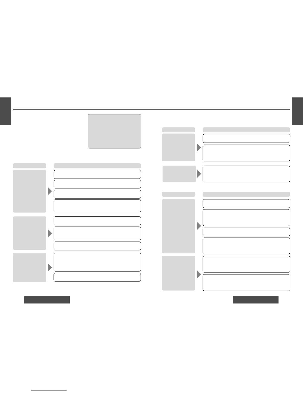
Preliminary Steps
Check and take steps as described in the tables below.
If You Suspect Something Wrong
Immediately switch the power off.
Disconnect the power connector and check that there is neither smoke nor heat from the unit before asking for repairs.
Never try to repair the unit by yourself because it is dangerous
to do so.
No power.
Trouble
Car’s ignition switch is not on.
➡Turn your car’s ignition switch to ACC or ON.
Troubleshooting Tips
❐ Common
The power cord (battery, ACC and ground) is connected in the wrong way.
➡
Check the wiring.
Grounding wire is not correctly connected.
➡Connect the grounding wire to a metal part of the car.
Fuse is burnt out.
➡Call the store where you purchased the unit, or your nearest
Servicenter (see the attached sheet) and ask for fuse replacement.
No sound.
Mute is set to ON.
➡Set it to OFF.
The wiring of the speaker line is not correct, or a break or poor contact
arises.
➡
Check the wiring in accordance with the wiring diagram.
Condensation (dew).
➡Wait for a while before use.
Cautions:
• Do not use the unit if it malfunctions or if
there is something wrong.
• Do not use the unit in irregular condition, for example, without sound, or with
smoke or foul smell, which can cause
ignition or electric shock. Immediately
stop using it and call the store where
you purchased it.
Cause/Step
There is an electromagnetic-wave generator such as a cellular phone near the unit
or its electrical lines.
➡Keep an electromagnetic-wave generator such as a cellular phone away
from the unit and the wiring of the unit. In case that noise cannot be eliminated due to the wiring harness of the car, consult your dealer.
Noise.
Troubleshooting
❐ Radio
No power is supplied to the antenna amplifier (when using a film antenna, etc.).
➡
Check the wiring of the antenna amplifier battery lead.
The number of receivable stations is less than 6.
➡
Move to an area where receivable stations number is maximum, and
try presetting.
The number of auto preset
stations is less than 6.
Trouble Cause/Step
Antenna installation or wiring of antenna cable is faulty.
➡
Check whether the antenna mounting position and its wiring are correct. In addition, check to see whether the antenna ground is securely
connected to the chassis.
• Disc is dirty.
• Disc has scratches.
➡Clean disc, referring to the section on “Notes on Discs”.
Sound skips, bad sound
quality. (e.g. caused by
noise)
Disc is in the CD compartment but no sound is
made, or disc is ejected
automatically.
The disc is inserted upside down.
➡Place disc in the correct direction with the label side up.
❐ CD
• Disc is dirty.
• Disc has scratches.
➡Clean disc, referring to the section on “Notes on Discs”.
Trouble Cause/Step
A disc that has data other than CD-DA type is loaded.
➡Discs that have CD-DA type data should be used.
➡The unit may not successfully play back a CD-R/RW that is made in
combination of writing software, a CD recorder (CD-R/RW drive)
and a disc which are incompatible one another. Refer to instruc-
tions for the concerned devices for details.
➡The unit may not successfully play back a CD-R/RW that is made up
of a combination of writing software, a CD recorder (CD-R/RW
drive) and a disc which are incompatible with one another. Refer to
instructions for the concerned devices for details.
Poor reception or noise
Grounding wire is not correctly connected.
➡Connect the grounding wire to a metal part of the car.
Page 12
11
E
N
G
L
I
S
H
12
E
N
G
L
I
S
H
2322
CQ-C1200U/C1120U/C1110U/C1100U CQ-C1200U/C1120U/C1110U/C1100U
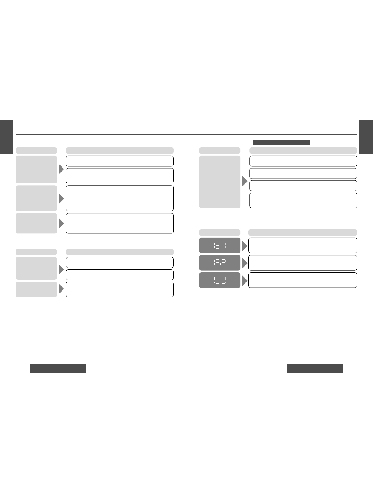
• Disc is defective.
• Mechanical trouble.
➡Press [u] (eject). If normal operation is not restored, call the store
where you purchased the unit or the nearest Servicenter to ask for
repairs.
Disc is not ejected.
❐ CD (Continued)
The first track of a mix mode disc was reproduced. (Mix mode is a format in which data except music is recorded on the first track and music
data is recorded on other than the first track in a session.)
➡Play back music data recorded on other than the first track.
Time is counted but no
sound comes out.
No sound from left,
right, front or rear
speakers.
Left and right balance, or front and rear balance is off on one side.
➡Adjust balance/fader setting as appropriate.
Cables are not correctly connected.
➡Connect the cables correctly.
❐ Sound Setting
The right speaker wire is connected to the left speaker and the left
speaker wire to the right speaker.
➡Connect the speaker wires to the correct ones.
Left and right sounds
are reversed in stereo
listening.
Trouble Cause/Step
Trouble Cause/Step
Mounting angle is over 30˚.
➡Adjust mounting angle to less than 30˚.
Instable mounting.
➡Mount the unit securely with the mounting parts, referring to the
section on installation.
Sound skips due to
vibration.
Troubleshooting (Continued)
Product Servicing
If the suggestions in the charts do not solve the problem, we recommend that you take it to your nearest
authorized Panasonic Servicenter. The product should be serviced only by a qualified technician.
Replace the Fuse
Use fuses of the same specified rating (15 A). Using different substitutes or fuses with higher ratings, or connecting the product directly without a fuse, could cause fire or damage to the unit.
If the replacement fuse fails, contact your nearest Panasonic Servicenter for service.
Error Display Messages
❐ CD
Disc has scratches.
➡Check the disc.
• Disc is dirty, or is upside down.
•A disc that has data other than CD-DA type is loaded.
➡Check the disc.
No operation by some cause.
➡If normal operation is not restored, call the store where you pur-
chased the unit or the nearest Servicenter to ask for repairs.
Display Cause/Step
Buttons are invalid for
operation.
Battery polarities are reversed.
➡Insert the battery correctly.
❐ Remote Control Unit
Wrong battery.
➡Check the battery.
Battery has run down.
➡Replace the battery.
Remote control unit is in the wrong direction.
➡Direct the remote control unit at sensor on the front panel.
Trouble Cause/Step
Only for CQ-C1200U/C1120U/C1110U
(The disc is ejected automatically)
(The disc is ejected automatically)
Page 13
13
E
N
G
L
I
S
H
14
E
N
G
L
I
S
H
2524
CQ-C1200U/C1120U/C1110U/C1100U CQ-C1200U/C1120U/C1110U/C1100U
❐ Cleaning this Unit
Use a dry, soft cloth to wipe.
❐ Caution on Cleaning
Never use solvents such as benzine, thinner as they
may mar the surface of the unit.
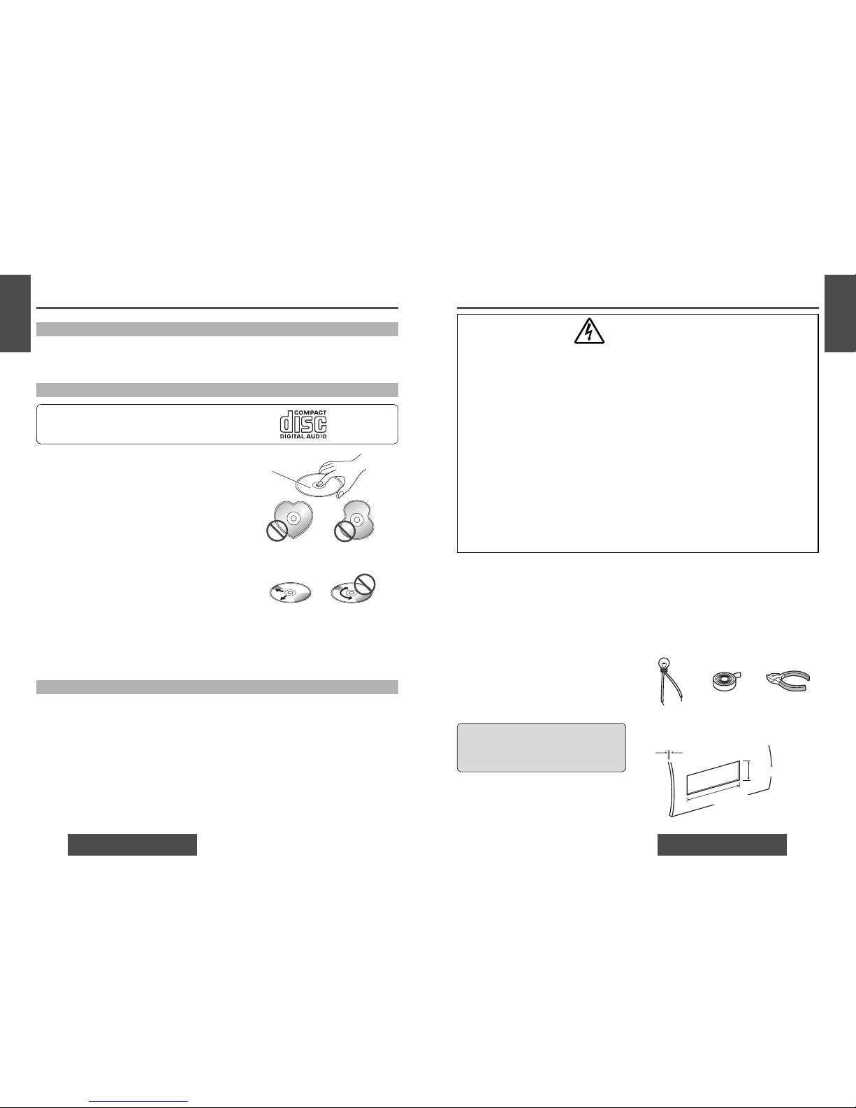
Label side
<Right> <Wrong>
Do not use irregularly shaped discs.
How to hold the disc
• Do not touch the underside of the disc.
• Do not scratch the discs.
• Do not bend disc.
• When not in use, keep the disc in the case.
Do not use irregularly shaped discs.
Do not leave discs in the following places:
• Direct sunlight
•Near car heaters
• Dirty, dusty and damp areas
• On seats and dashboards
Disc cleaning
Use a dry, soft cloth to wipe from the center outward.
Do not attach any seals or labels to your discs.
Do not write on the disc label in a heavy pen or ballpoint pen stroke.
Notes on discs
Do not play any ordinary music CDs with labels
other than this one.
Notes on CD-Rs/RWs
•You may have trouble playing back some CD-R/RW discs recorded on CD recorders (CD-R/RW drives),
either due to their recording characteristics or dirt, fingerprints, scratches, etc. on the disc surface.
• CD-R/RW discs are less resistant to high temperatures and high humidity than ordinary music CDs.
Leaving them inside a car for extended periods may damage them and make playback impossible.
• The unit may not successfully play back a CD-R/RW that was made by the combination of writing software, a CD recorder (CD-R/RW drive) and a disc if they are incompatible one another.
• This player cannot play the CD-R/RW discs if the session is not closed.
• This player cannot play the CD-R/RW discs which contains other than CD-DA data.
• Be sure to observe the instructions of CD-R/RW disc for handling it.
Care of the Unit
Maintenance Installation
WARNING
❐ This installation information is designed for experienced installers and is not
intended for non-technical individuals. It does not contain warnings or cautions of
potential dangers involved in attempting to install this product.
Any attempt to install this product in a motor car by anyone other than a qualified
installer could cause damage to the electrical system and could result in serious
personal injury or death.
❐ If your car is equipped with air bag and/or anti-theft systems, specific procedures
may be required for connection and disconnection of the battery to install this product.
Before attempting installation of this electronic component, contact your car dealer
or manufacturer to determine the required procedure and strictly follow their instructions.
FAILURE TO FOLLOW THE PROCEDURE MAY RESULT IN THE UNINTENDED DEPLOYMENT OF AIR BAGS OR ACTIVATION OF THE ANTI-THEFT SYSTEM RESULTING IN
DAMAGE TO THE VEHICLE AND PERSONAL INJURY.
Caution: This unit operates with a 12 V DC neg-
ative ground auto battery system only. Do not
attempt to use it in any other system. Doing so
could cause serious damage.
Min. 3⁄16" (4.75 mm)
Max. 7⁄32" (5.56 mm)
23⁄32" (53 mm)
75⁄32" (182 mm)
Thickness
❐ Overview
This product should be installed by a professional.
However, if you plan to install this product yourself,
your first step is to decide where to install it. The
instructions in these pages will guide you through
the remaining steps:
(Please refer to the “WARNING” statement above.)
• Identify and label the car wires.
• Connect the car wires to the wires of the power
connector.
• Install the unit in the dashboard.
• Check the operation of the unit.
If you encounter problems, please consult your nearest
professional installer.
Before you begin installation, look for the items which are
packed with your unit.
• Warranty Card…Fill this out promptly.
• Panasonic Servicenter List for Service Directory
…Keep for future reference in case the product needs
servicing.
• Installation Hardware…Needed for in-dash installation.
❐ Required Tools
You’ll need a screwdriver, a 1.5 V AA battery, and the following:
❐ Dashboard Specifications
12 V DC
Test bulb
Electrical
tape
Side-cut
pliers
Page 14
15
E
N
G
L
I
S
H
16
E
N
G
L
I
S
H
2726
CQ-C1200U/C1120U/C1110U/C1100U CQ-C1200U/C1120U/C1110U/C1100U
Caution: Connect the red power lead last, after
you have made and insulated all other connections.
Installation (Continued)
❐ Identify All Leads
The first step in installation is to identify all the car wires
you’ll use when hooking up your sound system.
As you identify each wire, we suggest that you label it
using masking tape and a permanent marker. This will
help avoid confusion when making connections later.
Note: Do not connect the power connector to the stereo
unit until you have made all connections. If there are no
plastic caps on the stereo hooking wires, insulate all
exposed leads with electrical tape until you are ready to
use them. Identify the leads in the following order.
Power Lead
If your car has a radio or is pre-wired for one:
Cut the connector wires one at a time from the plug (leaving the leads as long as possible) so that you can work
with individual leads.
Turn the ignition on to the accessory position, and ground
one lead of the test bulb to the chassis.
Touch the other lead of the test bulb to each of the
exposed wires from the cut radio connector plug. Touch
one wire at a time until you find the outlet that causes the
test bulb to light.
Now turn the ignition off and then on. If the bulb also
turns off and on, that outlet is the car power lead.
If your car is not wired for an audio unit:
Go to the fuse block and find the fuse port for radio
(RADIO), accessory (ACC), or ignition (IGN).
Battery Lead
If your stereo unit has a yellow lead, you will need to
locate the car’s battery lead. Otherwise you may ignore
this procedure. (The yellow battery lead provides continuous power to maintain a clock, memory storage, or other
function.)
If your car has a radio or is pre-wired for one:
With the ignition and headlights off, identify the car battery lead by grounding one lead of the test bulb to the
chassis and checking the remaining exposed wires from
the cut radio connector plug.
If your car is not wired for an audio unit:
Go to the fuse block and find the fuse port for the battery,
usually marked BAT.
Speakers
Identify the car speaker leads. There are two leads for
each speaker which are usually color coded.
A handy way to identify the speaker leads and the speaker
they are connected with is to test the leads using a 1.5 V
AA battery as follows.
Hold one lead against one pole of the battery and stroke
the other lead across the other pole. You will hear a scraping sound in one of the speakers if you are holding a
speaker lead.
If not, keep testing different lead combinations until you
have located all the speaker leads. When you label them,
include the speaker location for each.
Antenna Motor
If your car is equipped with an automatic power antenna,
identify the car motor antenna lead by connecting one
bulb tester lead to the car battery lead and touching the
remaining exposed wires from the cut radio connector
plug one at a time. You will hear the antenna motor activate when you touch the correct wire.
Antenna
The antenna lead is a thick, black wire with a metal plug at
the end.
❐ Connect All Leads
Now that you have identified all the wires in the car, you
are ready to begin connecting them to the stereo unit
wires. The wiring diagram (\ page 30) shows the proper
connections and color coding of the leads.
We strongly recommend that you test the unit before
making a final installation.
You can set the unit on the floor and make temporary connections to test the unit. Use electrical tape to cover all
exposed wires.
Ground
Connect the black ground lead of the power connector to
the metal car chassis.
Speakers
Connect the speaker wires. See the wiring diagram
(\ page 30) for the proper hookups. Follow the diagram
carefully to avoid damaging the speakers and the stereo
unit.
The speakers used must be able to handle more than 50
W (CQ-C1200U/C1120U)/45 W (CQ-C1110U/C1100U) of
audio power. If using an optional audio amplifier, the
speakers should be able to handle the maximum amplifier
output power. Speakers with low input ratings can be
damaged. Speaker impedance should measure 4–8 Ω,
which is typically marked on most speakers. Lower or
higher impedance speakers will affect output and can
cause both speaker and stereo unit damage.
Motor Antenna
Connect the car motor antenna lead to the dark blue
motor antenna relay control lead.
(Do not confuse the antenna lead with blue/white stripe
lead for a power amplifier.)
Battery
Connect the yellow battery lead to the correct radio wire
or to the battery fuse port on the fuse block.
Antenna
Connect the antenna by plugging the antenna lead into the
antenna receptacle.
Equipment
Connect any optional equipment such as an amplifier,
according to the instructions furnished with the equipment. Leave about 12" (30 cm) of distance between the
speaker leads/amplifier unit and the antenna/antenna
extension cord. Read the operating and installation
instructions of any equipment you will connect to this
unit.
Power
Connect the red power lead to the correct car radio wire
or to the appropriate fuse port on the fuse block.
If the stereo unit functions properly with all these connections made, disconnect the wires and proceed to the final
installation.
❐ Final Installation
Lead Connections
Connect all wires, making sure that each connection is
insulated and secure. Bundle all loose wires and fasten
them with tape so they will not fall down later. Now insert
the stereo unit into the mounting collar.
Congratulations! After making a few final checks, you’re
ready to enjoy your new auto stereo system.
❐ Final Checks
1. Make sure that all wires are properly connected and
insulated.
2. Make sure that the stereo unit is securely held in the
mounting collar.
3. Turn on the ignition to check the unit for proper operation.
If you have difficulties, consult your nearest authorized
professional installer for assistance.
Page 15
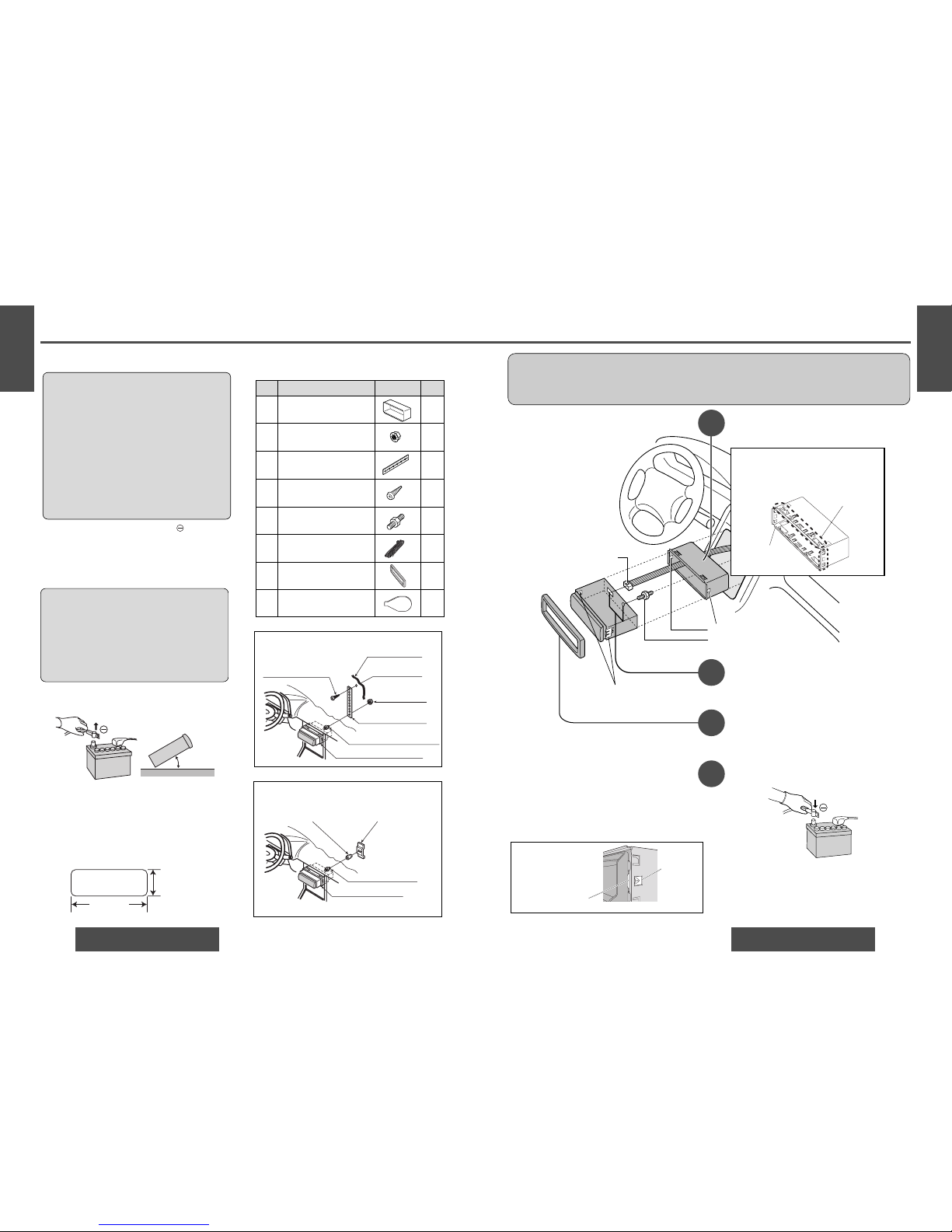
❐ Preparation
• Disconnect the cable from the negative battery
terminal (see warning and caution below).
• Remove Mounting Collar q and Trim Plate u from the
main unit temporarily, which are already mounted at
shipment.*
• Unit should be installed in a horizontal position with the
front end up at a convenient angle, but not more than 30°.
❐ Dashboard Installation
Installation Opening
This unit can be installed in any dashboard having
an opening as shown below. The dashboard should
be 3 ⁄ 16 " (4.75 mm)–7 ⁄ 32" (5.56 mm) thick in
order to be able to support the unit.
17
E
N
G
L
I
S
H
18
E
N
G
L
I
S
H
2928
CQ-C1200U/C1120U/C1110U/C1100U CQ-C1200U/C1120U/C1110U/C1100U
Cautions:
¡We strongly recommend that you wear gloves for installation work to protect yourself from injuries.
¡
When bending the mounting tab of the mounting collar with a screwdriver, be careful not to injure your
hands and fingers.
1
2
3
4
Mounting Holes
t Mounting Bolt
Insert Trim Plate u.
After installation reconnect the negative
(–) battery terminal.
First complete the electrical connections, and
then check them for correctness.(
a page 30)
The included Mounting Collar q is
designed specially for this unit. Do
not use it to attach any other model.
Mounting Springs (
C)
y Power Connector
Engage the Mounting
Springs (
C) in the
mounting holes of the
Mounting Collar q
firmly.
Mounting Spring
Mounting
Hole
Insert Mounting Collar q into the dashboard, and bend the mounting tabs out
with a screwdriver.
The tabs to be bent vary depending on
the car. To securely install the unit, fully
bend a number of the tabs so that there
is no rattling.
Example:
Tab
q Mounting
Collar
(a) Using the rear support strap e
r Tapping screw
(5 mmø×16 mm)
w Hex. nut
(5 mmø)
e Rear support strap
t Mounting bolt (5 mmø)
q Mounting collar
Fire wall of car
3 mmø
(b) Using the rubber cushion (option)
t Mounting bolt
(5 mmø)
q Mounting collar
Rear support bracket
(provided on the car)
Rubber cushion (option)
Establish the rear connection of the unit.
After fixing Mounting Bolt t and Power Connector
y, fix the rear of the unit to the car body by either
method (a) or (b) shown the previous page.
Installation (Continued)
❐ Installation Hardware
i
Dismounting Plate
(YFX214C323ZA)
1
2
Less than 30°
Caution: Various settings that have been stored in the
memory in other on-board equipment (car navigation
etc.) may be lost if the battery terminals are disconnected.
Therefore, we recommend to make a record of or to
back up the settings before disconnecting the terminals.
After completing installation of the main unit, set the
equipment again according to the record.
Warning: If your car is equipped with air bag
and/or anti-theft systems, specific procedures
may be required for connection and disconnection of the battery to install this product.
Before attempting installation of this electronic
component, contact your car dealer or manufacturer to determine the required procedure and
strictly follow their instructions.
FAILURE TO FOLLOW THE PROCEDURE MAY
RESULT IN THE UNINTENDED DEPLOYMENT OF
AIR BAGS OR ACTIVATION OF THE ANTI-THEFT
SYSTEM RESULTING IN DAMAGE TO THE VEHICLE AND PERSONAL INJURY.
ItemNo. Diagram Q’ty
t
y
u
Mounting Collar*
(FX0214C316ZA)
Hex. nut (5 mmø)
(YJN994C002ZA)
Rear support strap
(YFG044C002ZA)
Tapping screw (5 mmø×16 mm)
(XTT5+16AFK)
Mounting Bolt (5 mmø)
(YEJV014C002A)
Power Connector
(YEAJ02877)
Trim Plate*
(YFC054C063ZA)
1
1
1
1
1
1
q
w
e
r
(182 mm)
(53 mm)
7
5
/
32
"
23/
32
"
Page 16
(+)(–) (+)(–) (+)(–)(+)(–)
FRONT SP REAR SP
ACC
BATTERY 15A
1
3
2
S•W-OUT
19
E
N
G
L
I
S
H
20
E
N
G
L
I
S
H
3130
CQ-C1200U/C1120U/C1110U/C1100U CQ-C1200U/C1120U/C1110U/C1100U
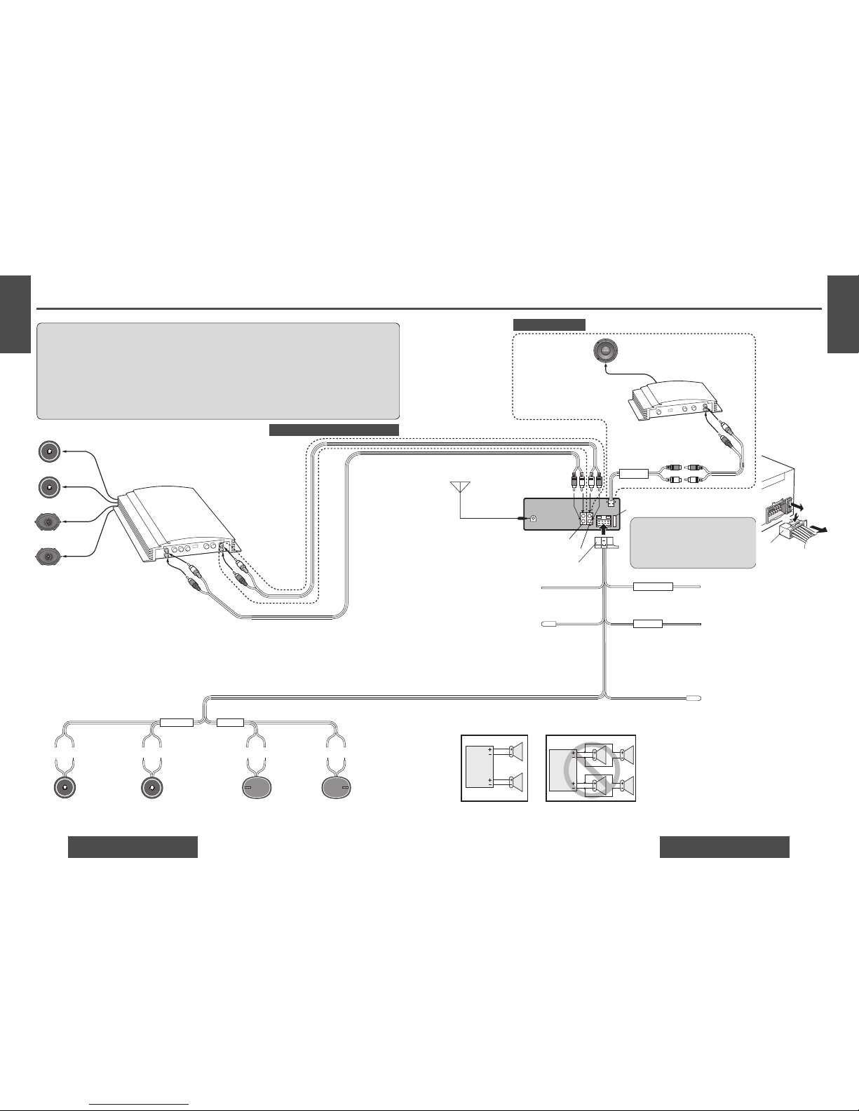
Electrical Connections
Cautions:
• This product is designed to operate with a 12 V DC, negative ground battery system.
•To prevent damage to the unit, be sure to follow the connection diagram below.
• Strip about 5 mm of the lead ends for connection.
• Do not insert the power connector into the unit until the wiring is completed.
• Be sure to insulate any exposed wires from a possible short-circuit from the car chassis. Bundle all cables
and keep cable terminals free from touching any metal parts.
• Remember, if your car has a drive computer or a navigation computer, the data of its memory may be
erased when the battery terminals are disconnected.
External Power Amplifier
CY-M7052
(option)
RCA Cord (option)
RCA Cord (option)
Sub-Woofer
cord (monaoural)
CQ-C1200U/C1120U
CQ-C1110U/C1100U
Sub-Woofer
(option)
Ground lead
To a clean, bare metallic part of car chassis.
Battery lead
To the car battery, continuous +12 V DC
Power lead
To ACC power, +12 V DC
Note: This lead is used for power control
when an external power amplifier is connected. The power supply of a power
amplifier will be activated when turning
on the power of this unit.
Amp. relay control power lead
(Max. 500 mA)
This lead is for connection to the power
amplifier.
Note: The power antenna extends automatically
when the FM/AM radio mode is selected.
Motor antenna relay control lead
(To motor antenna) (Max. 500 mA)
This lead is not intended for use with switch
actuated power antenna.
(Black) (Yellow)
Antenna
(R) Red
(L) White
y Power connector
Fuse (15 A)
C
(Red)
(Dark blue/white stripe)
(Dark blue)
y
Power
connector
Fuse
To remove
the Fuse
Only for CQ-C1200U
Only for CQ-C1200U/C1120U/C1110U
External Power Amplifier
CY-M9054
(option)
Speaker lead
System up
speakers
(White/
black
stripe)
Left speaker
(Front)
Right speaker
(Front)
Left speaker
(Rear)
Right speaker
(Rear)
(White) (Gray/black
stripe)
(Gray) (Green/black
stripe)
(Green) (Violet/
black
stripe)
(Violet)
C If the fuse (rear panel) blows fre-
quently, they may be something
wrong with the unit or wiring. Consult
your nearest Panasonic Servicenter
for service.
(L) White
(R) Red
Speaker connections
• Do not connect more than one speaker to one set of speaker leads (except for
connecting to a tweeter).
• Do not use a 3-wire type speaker system having a common earth lead.
L
R
L
R
Preamp. output connector (rear)
Preamp. output connector (front)
Note: A bridge connection should be
used when connecting only 2 channels
such as CQ-C1100U connection.
Page 17
21
E
N
G
L
I
S
H
22
E
N
G
L
I
S
H
3332
CQ-C1200U/C1120U/C1110U/C1100U CQ-C1200U/C1120U/C1110U/C1100U
❐ General
Power supply: 12 V DC (11 V–16 V), test voltage 14.4 V, negative ground
Current consumption: Less than 2.2 A (CD play mode; 0.5 W×4 channels)
Maximum power output: 50 W×4 channels at 1 kHz, volume control maximum (CQ-C1200U/C1120U)
45 W×4 channels at 1 kHz, volume control maximum (CQ-C1110U/C1100U)
Tone adjustment range:
Bass: ±12 dB at 100 Hz
Treble: ±12 dB at 10 kHz
Suitable speaker impedance: 4–8 Ω
Preamp output voltage: 2.0 V (CD play mode; 1 kHz, 0 dB)
Output impedance: 200 Ω
Sub-Woofer output voltage: 2.0 V (CQ-C1200U)
Sub-Woofer output impedance: 200 Ω (CQ-C1200U)
Dimensions (W×H×D): 7"×1
15
/16"
×5
7
/8"
(178×50×155 mm)
Weight: 3 lbs. 1 oz (1.4 kg)
❐ FM Stereo Radio
Frequency range: 87.9 MHz–107.9 MHz
Usable sensitivity: 11.0 dBf. (1.25 µ
V,
75 Ω)
50 dB quieting sensitivity: 15.2 dBf. (1.6 µ
V,
75 Ω)
Frequency response: 30 Hz–15 kHz (±3 dB)
Alternate channel selectivity: 75 dB
Stereo separation: 42 dB (1 kHz)
Image response ratio: 75 dB
IF response ratio: 100 dB
Signal/noise ratio: 70 dB
❐ AM Radio
Frequency range: 530 kHz–1 710 kHz
Usable sensitivity: 28 dB/µV (25 µ
V,
S/N 20 dB)
❐ CD Player
Sampling frequency: 8 times oversampling
DA converter: 1 bit DAC system
Error correction system: Panasonic super decoding algorithm
Pick-up type: Astigma 3-beam
Light source: Semiconductor laser
Wave length: 780 nm
Frequency response: 20 Hz–20 kHz (±1 dB)
Signal/noise ratio: 96 dB
Total harmonic distortion: 0.01 % (1 kHz)
Wow and flutter: Below measurable limits
Channel separation: 75 dB
Above specifications comply with EIA standards.
Note: Specifications and the design are subject to modification without notice due to improvements in technology.
Specifications
1
2
1
2
3
4
Switch off the power of the unit.
Remove the removable face plate.
q Press []. The removable face plate will
be opened.
w Push the face plate to either the right or
left.
e Pull it out towards you.
Remove the Trim Plate u with a screwdriver.
q Insert the Dismounting plate i along
the grooves on both sides of the main
unit until
“
click”is heard.
w Pull out the unit while pushing the plates
further inside.
Remove the unit by pulling with both hands.
Contact
q Press
u Trim Plate
Screwdriver
i Dismounting plate
Insert the tab
end in the
outer groove.
“
Click
”
q Insert
w Pull out
w
To Remove the Unit
5
 Loading...