

Page 1

Panasonic
a
Section 300
Installation
(Applies to CPC-AII/B Version 9.2
and CPC-EX Version 2.3)
Version 2.3/9.2
Revised April 2000
Page 2

Warning:
technicians only and is not designed for use by the general public. It does not
contain warnings or cautions to advise non-technical individuals of potential
dangers in attempting to service a product. Products powered by electricity
should be serviced or repaired only by experienced professional technicians.
Any attempt to service or repair the product or products de alt with in this
service information by anyone else could result in serious injury or death.
This service information is designed for experienced repair
The contents of this manual are subject to change without notice and do not constitute a
commitment on the part of Panasonic Telecommunication Systems Company (PTSC). Every
effort has been made to ensure the accuracy of this document. However, due to ongoing product
improvements and revisions, Panasonic cannot guarantee the accuracy of printed material after
the date of publication nor can it accept responsibility for errors or omissions. Panasonic will
update and revise this document as needed.
This document may be reproduced either electronically or in print as needed by certified dealers
and technicians of DBS products. However, the information contained in this document must not
be altered, copied, or changed in any way that misrepresents the installation, operation, or other
function or feature of the DBS product or Panasonic. Panasonic assumes no liability for any
alteration or misrepresentation of information contained herein.
The software and hardware described in this document may be used or copied only in accordance
with the terms of the license pertaining to said software or hardware.
Copyright 1995 by Panasonic Telecommunication Systems Company
Revised April 2000
All rights reserved.
Page 3

Table of Contents
Purpose ...................................................................................................................................... xi
Related Documents ................................................................................................................... xi
Chapter 1 Requirements .......................................... 1-1
Model Numbers ......................................................................................................................1-1
FCC Requirements .................................................................................................................. 1-1
General Requirements ............................................................................................................. 1-1
DID Requirements .................................................................................................................. 1-3
T1 Requirements .....................................................................................................................1-4
Environmental Requirements ................................................................................................. 1-4
Cleaning ..................................................................................................................................1-5
Chapter 2 System Overview .................................... 2-1
Cabinet Description ................................................................................................................2-3
Configurations ........................................................................................................................2-5
Printed Circuit Cards .............................................................................................................. 2-6
Processor Description ............................................................................................................. 2-9
Chapter 3 Cabinet Installation ................................. 3-1
Wall-Mounting the Cabinet .................................................................................................... 3-3
Guidelines ...............................................................................................................................3-3
Installation ..............................................................................................................................3-3
Grounding ...............................................................................................................................3-5
Guidelines ...............................................................................................................................3-5
Installation ..............................................................................................................................3-5
Card Installation ...................................................................................................................... 3-6
Guidelines ...............................................................................................................................3-6
Installation ..............................................................................................................................3-8
Battery Backup ....................................................................................................................... 3-9
Guidelines ...............................................................................................................................3-9
Installation for the DBS 40 ................................................................................................... 3-10
Installation for the DBS 72 and 96 ....................................................................................... 3-11
Key Phone Wall Mounting ................................................................................................... 3-13
DSLT Wall Mounting ...........................................................................................................3-15
System Initialization ............................................................................................................. 3-17
Test Phone ............................................................................................................................. 3-18
Guidelines .............................................................................................................................3-18
Installation ............................................................................................................................3-18
DBS-2.3/9.2-300 DBS Manual - Revised April 2000 iii
Page 4

Contents Section 300-Installation
Chapter 4 Trunks and Lines .................................... 4-1
Trunks .....................................................................................................................................4-3
Trunk Connectors ................................................................................................................... 4-3
Trunk Connector Pinouts ........................................................................................................4-4
Loop-Start Trunks ...................................................................................................................4-7
Ground Start and DID Trunks ................................................................................................ 4-9
T1 Interface ...........................................................................................................................4-11
Lines ......................................................................................................................................4-31
Extension Connectors ...........................................................................................................4-31
Extension Connector Pinouts ................................................................................................4-32
Analog Extensions ................................................................................................................ 4-37
Digital Extensions ................................................................................................................. 4-41
Trunk and Line Expansion ....................................................................................................4-44
Chapter 5 Peripheral Equipment ............................. 5-1
Local Terminal or SMDR Device ........................................................................................... 5-3
Guidelines ...............................................................................................................................5-3
Installation ..............................................................................................................................5-4
Remote Administration Interface (RAI) ................................................................................. 5-6
Guidelines ...............................................................................................................................5-6
Installation ..............................................................................................................................5-6
Background Music/Music-On-Hold ....................................................................................... 5-8
Guidelines ...............................................................................................................................5-8
Installation ..............................................................................................................................5-8
Off-Premises Adaptor (OPX) ............................................................................................... 5-10
Guidelines .............................................................................................................................5-10
Installation ............................................................................................................................5-11
Paging ...................................................................................................................................5-14
Guidelines .............................................................................................................................5-14
External Page Zone Installation ............................................................................................ 5-14
External General Page/UNA Installation ..............................................................................5-16
External Ringer (UNA Device) ............................................................................................ 5-17
Guidelines .............................................................................................................................5-17
Installation ............................................................................................................................5-18
Power Failure Unit ................................................................................................................5-19
Guidelines .............................................................................................................................5-19
Installation ............................................................................................................................5-19
Voice Announce Unit (VAU) ............................................................................................... 5-22
Guidelines .............................................................................................................................5-22
Installation ............................................................................................................................5-22
Recording and Playing Messages ......................................................................................... 5-26
Door Box Adaptor (Trunk Port) ...........................................................................................5-27
Guidelines .............................................................................................................................5-27
iv DBS Manual - Revised April 2000 DBS-2.3/9.2-300
Page 5

Section 300-Installation Contents
Installation ............................................................................................................................5-28
Door Box Adaptor (Extension Port) .....................................................................................5-31
Single Line Telephone Adaptor ............................................................................................ 5-34
Chapter 6 Double-Cabinet Systems ....................... 6-1
Guidelines ...............................................................................................................................6-3
Installation ............................................................................................................................6-10
Chapter 7 Specifications ......................................... 7-1
Electrical Characteristics ........................................................................................................ 7-3
Environmental Requirements ................................................................................................. 7-4
Resource Maximums ..............................................................................................................7-5
Cabling Specifications .......................................................................................................... 7-13
Communication Parameters ..................................................................................................7-14
Signaling Characteristics ......................................................................................................7-15
Tone Characteristics ............................................................................................................. 7-16
Appendix A: CPC-EX 1.0 Updates ...........................A-1
Compatibility ......................................................................................................................... A-1
44-Series Phone Support ........................................................................................................A-1
Directory Mode ......................................................................................................................A-2
Variable Mode ....................................................................................................................... A-2
Handset Mute ......................................................................................................................... A-2
Off-Hook Monitoring ............................................................................................................A-2
Analog Adapter ......................................................................................................................A-2
MSG (Message) Key ............................................................................................................. A-2
DSS/72 and EM/24 - Key Arrangement ................................................................................ A-2
FF-Key Programming ............................................................................................................ A-3
Speed Dial Enhancements ..................................................................................................... A-3
Additional Serial Port ............................................................................................................ A-3
T1 Networking Capability ..................................................................................................... A-3
Modification to Toll Restriction Service ............................................................................... A-3
Maximum Time Priority Route Tables .................................................................................. A-3
SMDR Modifications .............................................................................................................A-4
ISDN Support ........................................................................................................................ A-4
Modification to T1 Signaling Types ...................................................................................... A-4
Installation Notes ................................................................................................................... A-4
CPC-EX Installation .............................................................................................................. A-4
44-Series Enhanced Phone Features ...................................................................................... A-7
Analog Adapter ....................................................................................................................A-12
MSG (Message) Key ........................................................................................................... A-13
DSS/72 Console - Key Arrangement ...................................................................................A-15
DBS-2.3/9.2-300 DBS Manual - Revised April 2000 v
Page 6

Contents Section 300-Installation
EM/24 - Key Arrangement .................................................................................................. A-17
Additional Serial Port on CPC Card .................................................................................... A-19
Appendix B: CPC-AII/B 8.0 Updates ........................B-1
Contents ..................................................................................................................................B-2
44-Series Phone Support .........................................................................................................B-3
Enhanced Phone Features .......................................................................................................B-4
Analog Adapter .......................................................................................................................B-8
MSG (Message) Key ..............................................................................................................B-9
DSS/72 Console - Key Arrangement ....................................................................................B-10
EM/24 - Key Arrangement ...................................................................................................B-13
TAPI Support ........................................................................................................................B-14
Key Telephone Installation Notes .........................................................................................B-14
Desi Strip Cover ....................................................................................................................B-14
Key Telephone Wall Mounting Instructions ........................................................................B-14
Index ....................................................................Index-1
vi DBS Manual - Revised April 2000 DBS-2.3/9.2-300
Page 7

Section 300-Installation List of Figures
List of Figures
Figure 2-1. The DBS cabinet (DBS 96 shown) ................................................................. 2-3
Figure 2-2. The DBS cabinet (DBS 96 shown) ................................................................. 2-3
Figure 2-3. Trunk, line, and peripheral connections .......................................................... 2-4
Figure 2-4. Slot labels for printed circuit packages ...........................................................2-9
Figure 3-1. Cover removal ................................................................................................. 3-3
Figure 3-2. Cabinet mounting bracket ...............................................................................3-4
Figure 3-3. Cabinet wall-mounting ................................................................................... 3-4
Figure 3-4. Cabinet ground screw .....................................................................................3-5
Figure 3-5. SCC-B Switch 4 .............................................................................................. 3-6
Figure 3-6. CPC Strap S1 .................................................................................................. 3-7
Figure 3-7. Printed circuit card installation ....................................................................... 3-8
Figure 3-8. Battery location, DBS 40 .............................................................................. 3-10
Figure 3-9. Battery tray, DBS 72 and 96 .........................................................................3-11
Figure 3-10. Battery pack connection, DBS 72 and 96 ..................................................... 3-12
Figure 3-11. Wall-mount adaptor removal ........................................................................ 3-13
Figure 3-12. Wall-mount adaptor replacement .................................................................. 3-14
Figure 3-13. Handset guide insertion for wall-mounting, key phone ................................ 3-14
Figure 3-14. Desk stand removal for DSLT wall mounting ..............................................3-15
Figure 3-15. Desk stand attachment for DSLT wall mounting ......................................... 3-16
Figure 3-16. Handset guide insertion for wall-mounting, DSLT ...................................... 3-16
Figure 3-17. CPC memory clear switch ............................................................................ 3-17
Figure 3-18. Test telephone connection ............................................................................ 3-19
Figure 4-1. DBS trunk connections (DBS 96) ................................................................... 4-3
Figure 4-2. L-TRK Card Strap J1 and Switch Locations ................................................. 4-7
Figure 4-3. Attaching Caller ID Card to the L-TRK Card ................................................ 4-8
Figure 4-4. -48Vpower supply installation ......................................................................4-10
Figure 4-5. Connector 4 (CN4) strapping, Sync Unit ...................................................... 4-21
Figure 4-6. T1 Sync Unit installation .............................................................................. 4-22
Figure 4-7. T1 MDF card installation .............................................................................. 4-23
Figure 4-8. Sync Unit and T1 connection, single-cabinet installation ............................ 4-24
Figure 4-9. RJ48 pinouts, CN1 connector ....................................................................... 4-25
Figure 4-10. T1 cabinet connections, single-cabinet installation ...................................... 4-26
Figure 4-11. Sync cable connections, double-cabinet with a T1 in the slave .................... 4-28
Figure 4-12. Clock sync cable and sync cable connections, double-cabinet installation .. 4-30
Figure 4-13. DBS extension connections .......................................................................... 4-31
Figure 4-14. SLT ringer box installation .......................................................................... 4-38
Figure 4-15. EMI filter installation (DBS 40 only) ........................................................... 4-40
Figure 4-16. DSS/72 connection using one cable with two pairs. ..................................... 4-42
Figure 4-17. EM/24 connection using one cable with two pairs ....................................... 4-43
Figure 4-18. Trunk or extension expansion .......................................................................4-45
Figure 5-1. RS-232C connection ...................................................................................... 5-4
DBS-2.3/9.2-300 DBS Manual - Revised April 2000 vii
Page 8

List of Figures
Section 300-Programming
Figure 5-2. SMDR Format for CPC-AII and CPC-B Version 3.1 or higher ..................... 5-5
Figure 5-3. RAI connection............................................................................................... 5-7
Figure 5-4. Installation of music-on-hold and background music ..................................... 5-9
Figure 5-5. Cable punch-out plate, OPX Adaptor ........................................................... 5-11
Figure 5-6. OPX installation ............................................................................................ 5-13
Figure 5-7. External zone paging installation ..................................................................5-15
Figure 5-8. External general page/UNA installation ....................................................... 5-16
Figure 5-9. External ringer (UNA device) installation ....................................................5-18
Figure 5-10. Cable punch-out plate, Power Failure Unit .................................................. 5-20
Figure 5-11. Power Failure Unit (PFU) installation .......................................................... 5-21
Figure 5-12. Cable punch-out plate, Voice Announce Unit .............................................. 5-24
Figure 5-13. Extension cord connection to the VAU ....................................................... 5-25
Figure 5-14. Voice Announce Unit (VAU) installation ................................................... 5-25
Figure 5-15. Cable punch-out plate, Door Box Adaptor ................................................... 5-29
Figure 5-16. Installation of the door box, door opener, and door sensor .......................... 5-30
Figure 5-17. Cable punch-out plate, Door Box Adaptor ................................................... 5-31
Figure 5-18. Installation of the door box, door opener ......................................................5-32
Figure 5-19. Connections to the Door Box Adaptor ........................................................ 5-33
Figure 5-20. Cable punch-out plate, SLTA .......................................................................5-34
Figure 5-21. SLTA installation ......................................................................................... 5-36
Figure 6-1. Slot usage for two-cabinet systems, DBS 40 + DBS 40 .................................6-4
Figure 6-2. Slot usage for two-cabinet systems, DBS 72 + DBS 40 .................................6-5
Figure 6-3. Slot usage for two-cabinet systems, DBS 72 + DBS 72 .................................6-6
Figure 6-4. Slot usage for two-cabinet systems, DBS 96 + DBS 40 .................................6-7
Figure 6-5. Slot usage for two-cabinet systems, DBS 96 + DBS 72 .................................6-8
Figure 6-6. Slot usage for two-cabinet systems, DBS 96 to DBS 96 ................................ 6-9
Figure 6-7. Strap 3, MFR card ......................................................................................... 6-10
Figure 6-8. Double-cabinet installation ........................................................................... 6-11
Figure 6-9. CBL-S to Connector Panel connection, slave cabinet .................................. 6-11
viii DBS Manual - Revised April 2000 DBS-2.3/9.2-300
Page 9

Section 300-Installation List of Tables
List of Tables
Table 1-1. DBS model numbers .......................................................................................1-1
Table 1-2. FCC information ............................................................................................. 1-2
Table 1-3. Interface information ...................................................................................... 1-2
Table 2-1. Trunk and extension capacities according to system size ............................... 2-5
Table 2-2. Printed circuit card descriptions and maximums ............................................ 2-6
Table 2-3. Printed circuit package slot usage ...................................................................2-8
Table 2-4. CPC/SCC features ........................................................................................... 2-9
Table 3-1. Battery backup packages for the DBS 40, 72, and 96 .................................... 3-9
Table 4-1. Main trunks and expansion trunks provided with each system type .............. 4-4
Table 4-2. Pinouts and trunk numbers for the main trunk connector............................... 4-5
Table 4-3. Pinouts and trunk numbers for trunk expansion connector CN1 ....................4-6
Table 4-4. -48V current consumption for ground-start and DID trunks .......................... 4-9
Table 4-5. -48V power supplies tested with the DBS ..................................................... 4-9
Table 4-6. T1 Hardware requirements for single-cabinet systems ................................. 4-11
Table 4-7. T1 Hardware requirements for double-cabinet systems ............................... 4-12
Table 4-8. T1 slot usage for two-cabinet systems .......................................................... 4-13
Table 4-9. T1 and analog trunk assignments, DBS 40 ...................................................4-14
Table 4-10. T1 and analog trunk assignments, DBS 72 ...................................................4-14
Table 4-11. T1 and analog trunk assignments, DBS 96 ...................................................4-15
Table 4-12. Maximum T1 assignments for two-cabinet systems ..................................... 4-15
Table 4-13. T1 and analog trunk assignments, DBS 40 + 40 (16-channel fractional T1 in the
slave) 4-16
Table 4-14. T1 and analog trunk assignments, DBS 72 + DBS 72 (24-channel T1 in the slave)
4-16
Table 4-15. T1 and analog trunk assignments, DBS 96 + DBS 40 (24-channel T1 in the master;
16-channel T1 in the slave) 4-17
Table 4-16. T1 and analog trunk assignments, DBS 96 + DBS 72 (24-channel T1 in the master;
24-channel T1 in the slave) 4-18
Table 4-17. T1 and analog trunk assignments, DBS 96 + DBS 96 (24-channel T1 in the master;
24-channel T1 in the slave) 4-19
Table 4-18. Extension ports provided with each system ................................................. 4-32
Table 4-19. Pinouts and color codes for extension connector CN12 ............................... 4-33
Table 4-20. Pinouts and color codes for extension connector CN13 ............................... 4-34
Table 4-21. Pinouts and color codes for extension connector CN14 ............................... 4-35
Table 4-22. Pinouts and color codes for extension expansion connector CN1 ................4-36
Table 5-1. RS-232C pin designations used for CN6 ........................................................5-3
Table 5-2. RAI compatibility ........................................................................................... 5-6
Table 5-3. Maximum distances for direct connection to OPX stations ........................ 5-10
Table 5-4. Switch settings for SW1, VAU .....................................................................5-22
Table 5-5. Switch settings for delay answer timing, VAU ........................................... 5-23
Table 5-6. Switch settings for DTMF detection timing, VAU ....................................... 5-23
DBS-2.3/9.2-300 DBS Manual - Revised April 2000 ix
Page 10

List of Tables
Section 300-Installation
Table 5-7. Switch settings for wait timing between dialed digits, VAU ....................... 5-23
Table 5-8. Switch settings for abbreviated dialing digit length, VAU ........................... 5-24
Table 5-9. Maximum distances for SLTA installation ................................................... 5-35
Table 6-1. Trunk and extension port maximums for double-cabinet systems ................. 6-3
Table 7-1. Input power ..................................................................................................... 7-3
Table 7-2. Power consumption and heat generation ........................................................ 7-3
Table 7-3. Battery backup capacity ..................................................................................7-3
Table 7-4. Temperature and humidity requirements ........................................................ 7-4
Table 7-5. Dimensions and weight, single-cabinet systems and phones ......................... 7-4
Table 7-6. Dimensions for two-cabinet systems ..............................................................7-4
Table 7-7. Trunk and line capacities ................................................................................ 7-5
Table 7-8. Feature-related capacities ............................................................................... 7-5
Table 7-9. Hardware maximums for single-cabinet systems .......................................... 7-7
Table 7-10. Hardware maximums for double-cabinet systems ........................................7-10
Table 7-11. Maximum cabling distances ......................................................................... 7-13
Table 7-12. Voice path from KTELs to DBS ................................................................... 7-14
Table 7-13. Data communications ports .......................................................................... 7-14
Table 7-14. Signaling to CO ............................................................................................ 7-15
Table 7-15. Signaling levels .............................................................................................7-15
Table 7-16. Transmission specifications ..........................................................................7-15
Table 7-17. Tone Plan ...................................................................................................... 7-16
Table 7-18. DTMF frequencies ........................................................................................ 7-17
x DBS Manual - Revised April 2000 DBS-2.3/9.2-300
Page 11

Section 300-Installation About This Manual
About This Manual
Purpose
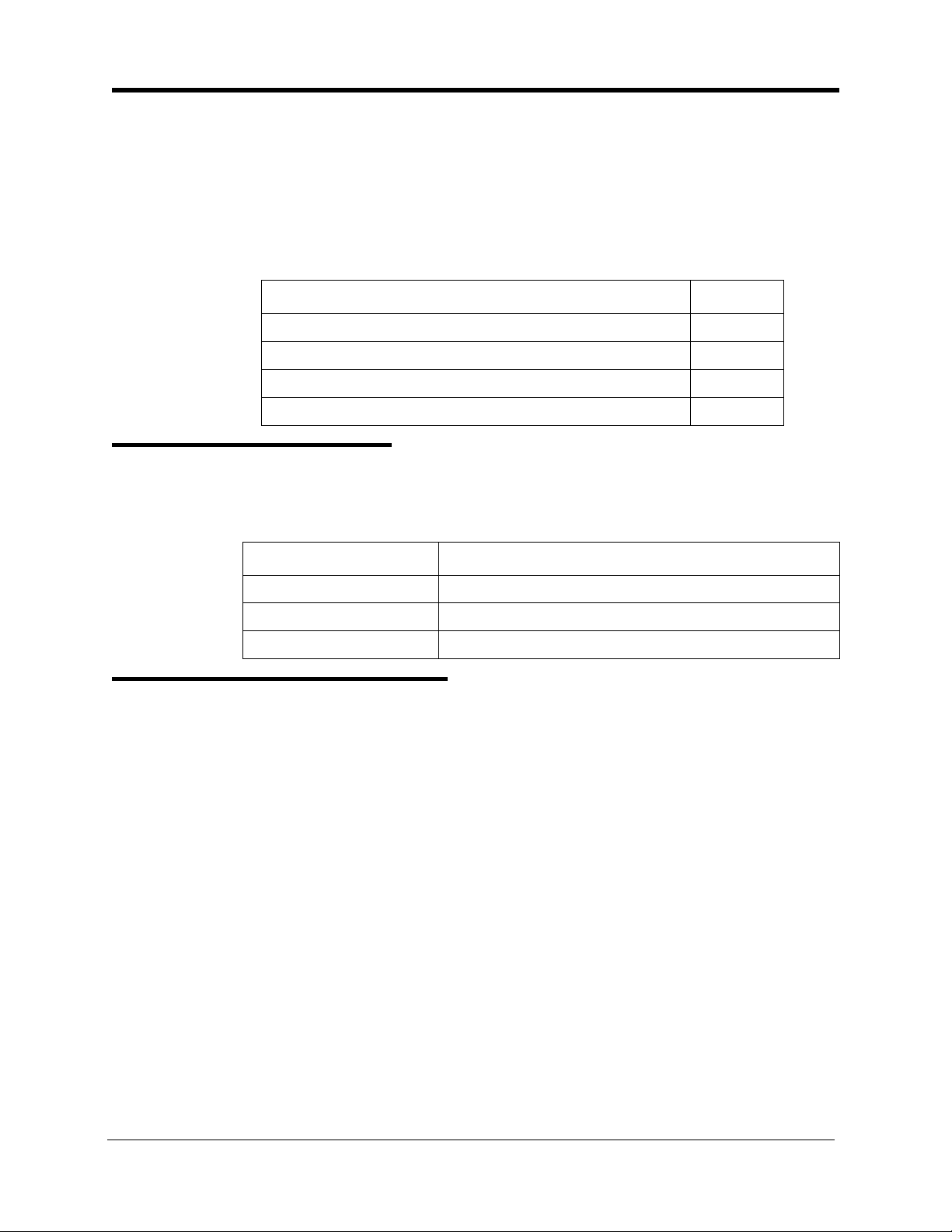
This manual provides installation instructions for the Digital Business System
(DBS). The following table summarizes the purpose of each chapter.
Chapter
No.
1 Requirements Includes DBS model numbers and FCC information that
2 System Overview Provides an overview of the DBS. The overview includes
3 Cabinet Installation Explains how to install and power up the cabinet. Before
4 Trunks and Lines Describes trunk and line installation. See the “Peripheral
5 Peripheral
Title Purpose
may be required during installation. In addition,
environmental requirements are included to ensure proper
operation.
descriptions of the cabinet, system configurations, printed
circuit cards, and the call processor.
you begin installation, be sure to read Chapter 1 “Requirements.”.
Equipment” chapter for instructions on connecting
peripheral equipment through trunks or lines.
Describes peripheral equipment installation. Some
Equipment
peripheral equipment also requires trunk and/or line
interfaces (door phones or power failure units, for
example). For information on trunk and line connections,
see Chapter 4.
6 Double-Cabinet
Systems
7 Specifications Contains frequently referenced DBS specifications.
Explains installation procedures for two-cabinet systems.
Related Information
Appendix A and Appendix B, located in the back of this manual.
For instructions on DBS programming, see Programming Guidance (Section
400).
For detailed descriptions of DBS features, see Feature Operation (Section
700).
DBS-2.3/9.2-300 DBS Manual - Revised April 2000 xi
Page 12

About This Manual
Section 300-Installation
xii DBS Manual - Revised April 2000 DBS-2.3/9.2-300
Page 13
Chapter 1. Requirements
This chapter includes DBS model numbers and FCC information that may be
required during installation. In addition, environmental requirements for proper
operation are included.
This chapter covers the following topics:
FCC Requirements 1-1
Environmental Requirements 1-4
Cleaning 1-5
Model Numbers
Table 1-1. DBS model numbers
DBS System Model Number
DBS 40 VB-43030
DBS 72 VB-43050
DBS 96 VB-43060
FCC Requirements
Topic
Page
1-1
General Requirements
• The Federal Communications Commission (FCC) has established Rules
which permit the DBS to be directly connected to the telephone network.
Standardized jacks are used for these connections. This equipment should
not be used on party lines or coin lines.
• Key FCC information appears in the following table.
• Before connecting the DBS, provide the telephone company with the
following information
DBS-2.3/9.2-300 DBS Manual - Revised April 2000 1-1
Page 14
Section 300-Installation Chapter 1. Requirements
Table 1-2. FCC information
Item Specification
FCC Registration
Number
Ringer Equivalence 0.5B *
Network Address
Signaling Code
* The ringer equivalence number (REN) is usef ul to determine the quantity of
devices that you may connect to your telephone line and still have all of those
devices ring when your number is called. In most areas, the sum of the RENs
of all devices on any one line should not exceed five (5.0). To be certain of
the number of devices you may connect to your line, as determined by the
REN, you should call your telephone company to determine the maximum
REN for your calling area.
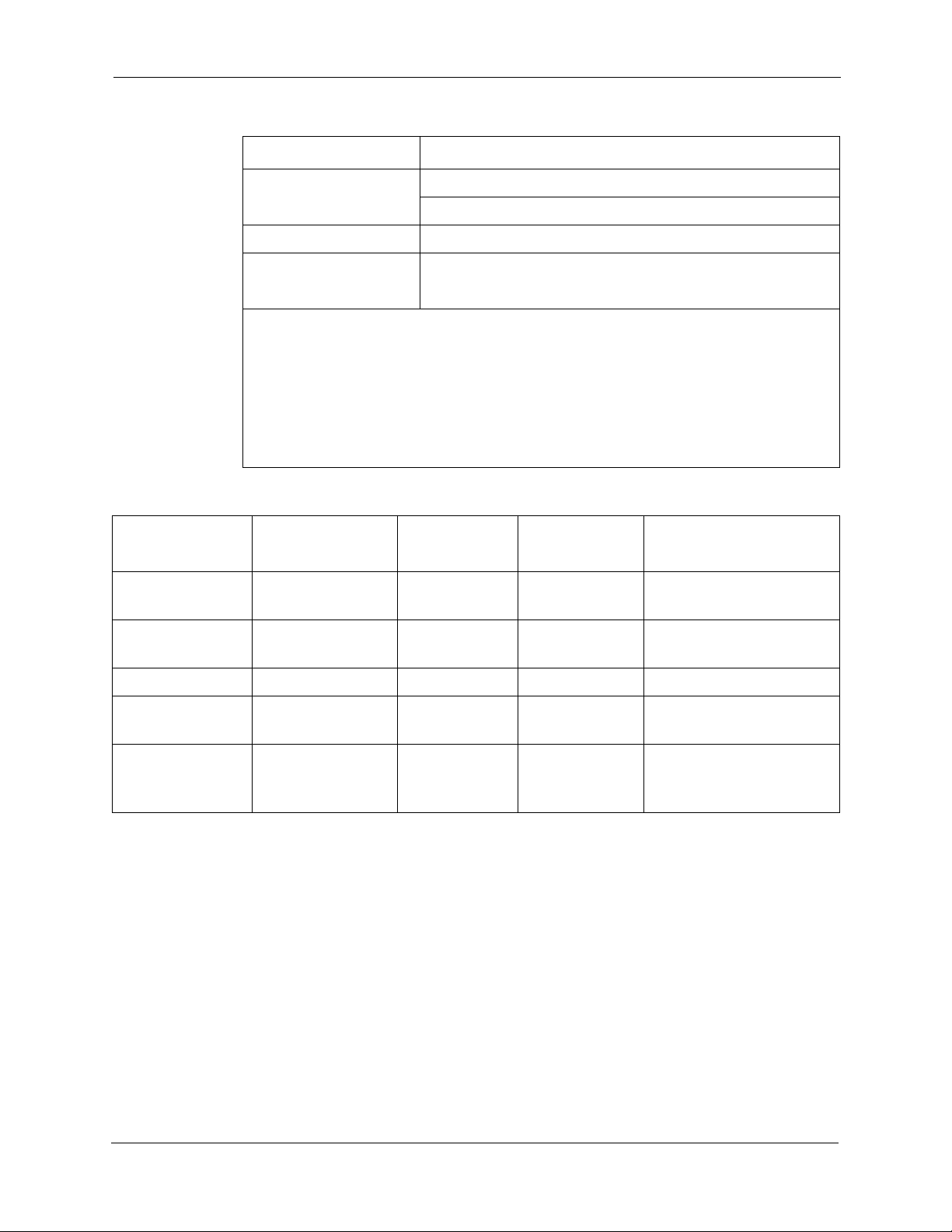
Table 1-3. Interface information
Port Type
Loop Start
Type of
Interface
2-wire loop RJ21X 9.0F 02LS2
Trunk
When used as a key system: ACK4A4-60490-KF-E
When used as a PBX: ACK4A4-60489-MF-E
E
USOC Jack
Connector
Service
Order Code*
Facility Interface
Code
Ground Start
2-wire ground RJ21X 9.0F 02GS2
Trunk
DID Trunk 2-wire DID RJ21X 9.0F 02RV2-T
T1 Trunk T1 RJ48C 6.0F 04DU9-DN,
04DU9-1SN
OPX Adaptor OPX RJ21X (at
DBS DBS)
9.0F 0L13A
0L13B
0L13C (recommended)
• This equipment complies with Part 68 of the FCC Rules. On the left cover
panel of this equipment is a label that contains, among other information, the
FCC registration number and Ringer Equivalence Number (REN) for this
equipment. If requested, provided this information to your telephone
company.
• If the DBS telephone equipment caused harm to the Telephone Network, the
Telephone Company may discontinue your service temporarily. If possible,
they will notify you in advance. But if advance notice isn’t practical, you
will be notified as soon as possible. You will be advised of your right to file
a complaint with the FCC.
• Under the FCC Rules, no customer is authorized to repair this equipment.
This restriction applies regardless of whether the equipment is in or out of
DBS-2.3/9.2-300 DBS Manual - Revised April 2000 1-2
Page 15

Chapter 1. Requirements
• The Telephone Company may make changes in its facilities, equipment,
• The Digital Key Telephones designed for use with this system are hearing
• This equipment is capable of providing users access to interstate providers
• If you experience trouble with the DBS, please contact Panasonic
Section 300-Installation
warranty. However, the customer may replace fuses, and plug-in cards, as
needed.
operations or procedures, that could affect the proper operation of your
equipment. If they do, you will be given advance notice so as to give you an
opportunity to maintain uninterrupted service.
aid compatible.
of operator services through the use of access codes. Modification of this
equipment by call aggregators to block access dialing codes is a violation of
the Telephone Operator Consumers Act of 1990.
Communication & Systems Company, Business Telephone Systems Division,
T wo Panasonic W ay Panazip 7B-3, Secaucus, NJ 07094 (Phone: (1-800-822-
0909) for repair/w arranty inform ation . Upon establ ishi ng cont act, properl y
identify the equipment, along with your company name/se rvice center , and
address. The telephone company may ask you to disconnect this equipment from
the network until the pr oblem has been corrected.
• The software contained in the DBS to allow user access to the network
must be upgraded to recognize newly established network area codes and
exchange codes as they are placed in service.
- F ailure to upgrade the premises systems of peripheral equipment
to recognize the new codes as they are established will restrict
the customer and the customer’s employees from gaining access
to the network and to these codes.
- Bell Communications Research (Bellcore) publishes the North
American Numbering Plan (NANP) information in paper,
microfiche and tape. An abbreviated summary of the newly
established area codes and exchange codes is also available.
Bellcore may be contacted on (908) 699 6700 to obtain
appropriate information to keep customer equipment upgraded.
DID Requirements
Allowing this equipment to be operated in such a manner as to not provide for
proper answer supervision is a violation of Part 68 of the FCC Rules.
Proper answer supervision is when:
A. This equipment returns answer supervision to the PSTN when DID calls a re:
- Answered by the called station
1-3 DBS Manual - Revised April 2000 DBS-2.3/9.2-300
Page 16

Section 300-Installation Chapter 1. Requirements
- Answered by the attendant
- Routed to a recorded announcement that can be administered by
the CPE user
- Routed to a dial prompt.
B. This equipment provides answer supervision on all DID calls forwarded to
the PSTN. Permissible exceptions are:
- A call is unanswered
- A busy tone is received
- a reorder tone is received
T1 Requirements
This device must only be connected to the T1 network connected behind an
FCC Part 68 registered channel service unit. Direct connection is not allowed.
Environmental Requirements
Temperature:
order to avoid component damage. Room temperatures should be 32 to 104° F
(0 to 40° C).
Humidity:
may rust metallic parts and degrade performance. Do not install the system
where humidity could condense on its surfaces. Relative humidity ranges
should be between 30 and 90 percent.
Ventilation:
circulation through the cabinet grille.
Gas and airborne particles:
contacts, the environment should be free from airborne particles and corrosive
gas.
Electrical noise:
noise, which could disturb the operation of digital circuits. The system should
be located at least 10 ft. (3 m) away from welders, dimmers, or other highcurrent machines. Phones connected to the system should not be located near
fluorescent lamps, air conditioners, washing machines, TVs, or radios.
The environment should be free from excessive temperatures in
The environment should be free from excessive humidity, which
Adequate ventilation must be provided to allow upward air
To avoid corrosion or oxidation of electrical
The environment should be free from excessive electrical
Vibration:
could loosen components.
Water Exposure:
dangerous. Do not place anything containing water on the system. Do not install
DBS-2.3/9.2-300 DBS Manual - Revised April 2000 1-4
The environment should be free from excessive vibration, which
Because the DBS is an electric device, exposure to water is
Page 17

Chapter 1. Requirements
under overhead plumbing, sprinkler system valves, or in areas that are
susceptible to flooding.
Section 300-Installation
Lighting:
Lightning Protection/Grounding:
protect from lightning damage. The following UL conditions must be met to
ensure proper grounding. (For grounding instructions, see page 3-5.)
• Supplemental and independent equipment grounding conductors are to be
installed between the system and the wiring system ground.
• One of the equipment grounding conductors must be a conductor that is as
large or larger than the ungrounded branch-circuit supply conductors. The
equipment grounding conductor is to be installed as part of the circuit that
supplies the system and is to be connected to ground at the service
equipment. Bare, covered, or insulated grounding conductors are acceptable.
Individually covered or insulated grounding conductors should have a
continuous outer finish that is either green or green with one or more yellow
stripes. The equipment grounding conductor should be connected to ground
at the service equipment.
• The other equipment grounding conductor shall comply with the general
rules for grounding contained in Article 250 of the National Electric Code,
NFPA 70, but its connection to ground shall not depend on the cord and plug
of the system.
Sufficient lighting is required for testing and maintenance.
The system must be properly grounded to
• The attachment-plug receptacles of the same type as that used by the
• A marking adjacent to the telecommunications jacks must instruct the user
Cleaning
•Use a slightly damp cloth to clean the phones. The phones should never be
systems that are in the vicinity of the DBS are all to be of a grounding type,
and the equipment grounding conductors serving these receptacles are to be
connected to earth ground at the service equipment.
to connect a supplementary equipment grounding conductor before any
telecommunication lines are connected to the product or system.
cleaned with benzene, paint thinner, or other solvents.
1-5 DBS Manual - Revised April 2000 DBS-2.3/9.2-300
Page 18

Chapter 1. Requirements
Section 300-Installation
1-6 DBS Manual - Revised April 2000 DBS-2.3/9.2-300
Page 19

Chapter 2. System Overview
This chapter gives an overview of the Digital Business System (DBS). This
overview includes descriptions of the DBS cabinet, system configurations,
printed circuit cards, and the call processor.
This chapter covers the following topics::
Topic
Cabinet Description 2-3
Configurations 2-5
Printed Circuit Cards 2-6
Processor Description 2-9
Page
DBS-2.3/9.2-300 DBS Manual - Revised April 2000 2-1
Page 20

2-2 DBS Manual - Revised April 2000 DBS-2.3/9.2-300
Page 21

Section 300-Installation Chapter 2. System Overview
Cabinet Description
Panasonic’s Digi tal Business System (DBS ) is a hybrid telephone system that
can be used as a key service unit (KSU) or a private branch exchange (PBX).
The DBS cabinet includes an AC power supply, backup batteries (optional),
dedicated card slots, and a central connector panel for line and trunk
connections.
Figure 2-1. The DBS cabinet (DBS 96 shown)
Connector Panel
Card
Slots
CN11
CN1
TRK 1 TRK2 TRK3 EC1 EC2 EC3 EC4 EC5 EC6 EC7 EC8 EC/ TRK S CC CPC AU X1 AU X2
SW 1
CN12
CN3
CN5 CN4
CN13
CN14
CN15
CN1
CN2
CN6
STATUS
LED
RAM H O LD
RAM C LR
Power Supply
Power Switch
Batteries
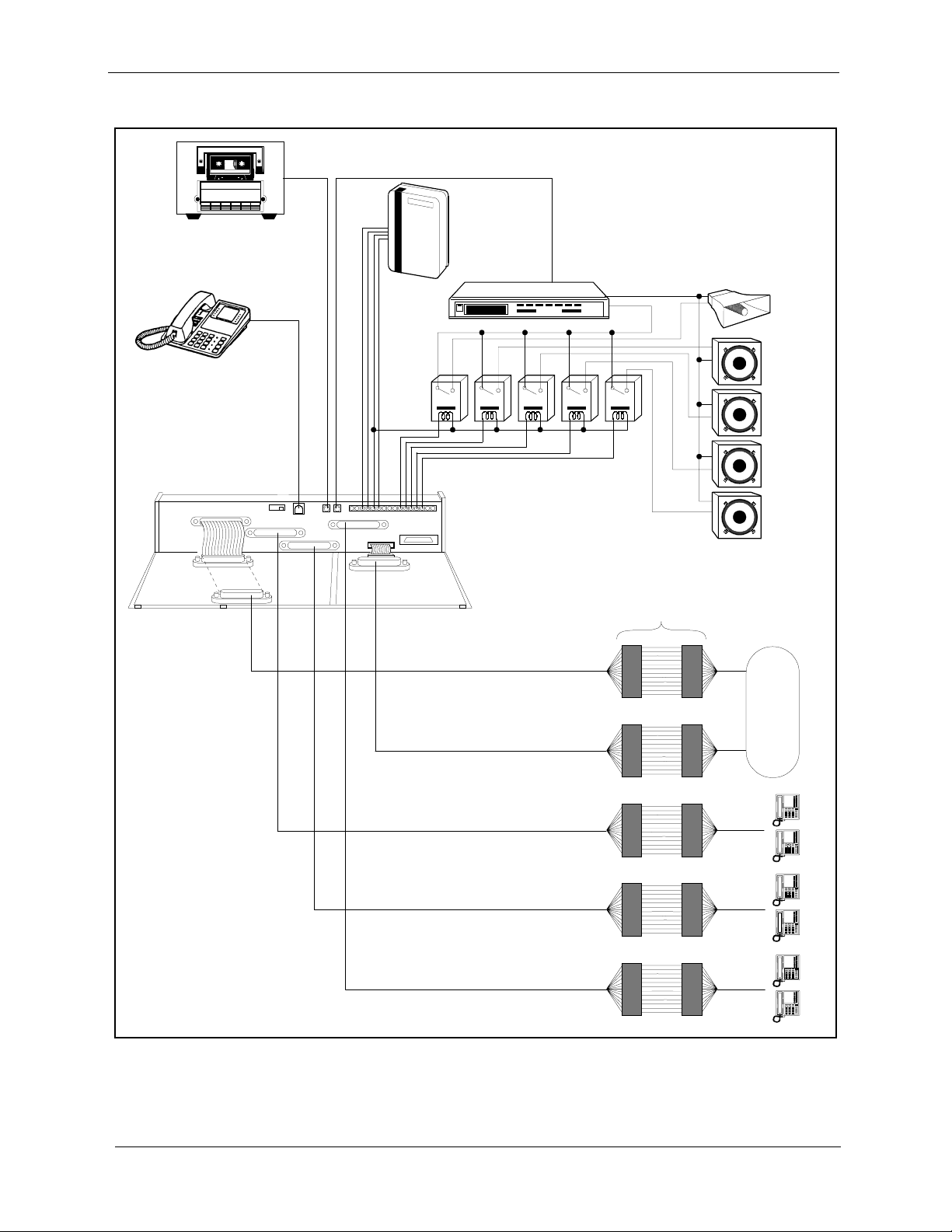
In addition to trunk and line connection, the connector panel is used to
connect peripheral equipment such as paging speakers, external ringers, and
music-on-hold/background music sources. Figure 2-2 on page 2-4 shows
trunk and line connections, as well as some peripheral connections.
Peripheral connections are covered in detail in Chapter 5, “Peripheral
Equipment.”
DBS-2.3/9.2-300 DBS Manual - Revised April 2000 2-3
Page 22
Chapter 2. System Overview
e
e
e
e
Figure 2-2. Trunk, line, and peripheral connections
A
Tape R ecorde r
forM usic- On-Hold
and B ackgr ound M usic
Test
Phone
Relays
#00 #01 #04#02 #03
SLT R ingerBox
(VB-2089P)
Amplifier
Section 300-Installation
All-Page
Speaker
Zone P ag
#01
Zone P ag
#02
Zone P ag
#03
CN11
CN1
CN12
CN3
CN5
CN13
CN4
CN14
CN2
CN15
CN1
Trunk Ports
1-24
Trunk Ports
25 -32
Extension Ports
1-24
Extension Ports
25 -48
MDF
Zone P ag
#04
CO
Extension Ports
49 -72
2-4 DBS Manual - Revised April 2000 DBS-2.3/9.2-300
Page 23

Section 300-Installation Chapter 2. System Overview
Configurations
The DBS comes in three models, which provide from 40 to 96 ports. Up to
two systems can be combined to increase port capacity up to 192 ports (DBS
96 + DBS 96).
In addition to dedicated trunk and extension slots, each system includes one
expansion slot (labeled EC/TRK) that can be used for either trunks or
extensions. The following table shows port capacities for individual systems
and for different combinations of systems.
Table 2-1. Trunk and extension capacities according to system size
System Size Trunk
Ports
DBS 40 8 24 8
DBS 72 16 48 8
DBS 96 24 64 8
DBS 40 + DBS 40 16 48 8 (See Note 1.)
DBS 72 + DBS 40 24 72 0 (See Note 2.)
DBS 72 + DBS 72 32 96 8 (See Note 1.)
DBS 96 + DBS 40 32 88 16
DBS 96 + DBS 72 40 112 16
DBS 96 + DBS 96 48 128 16
Notes:
1. The slave cabinet must be used for expansion ports.
2. When a DBS 72 and DBS 40 are connected, expansion ports cannot be used.
Extension
Ports
Expansion Ports
(Trunks or Extensions)
DBS-2.3/9.2-300 DBS Manual - Revised April 2000 2-5
Page 24

Chapter 2. System Overview
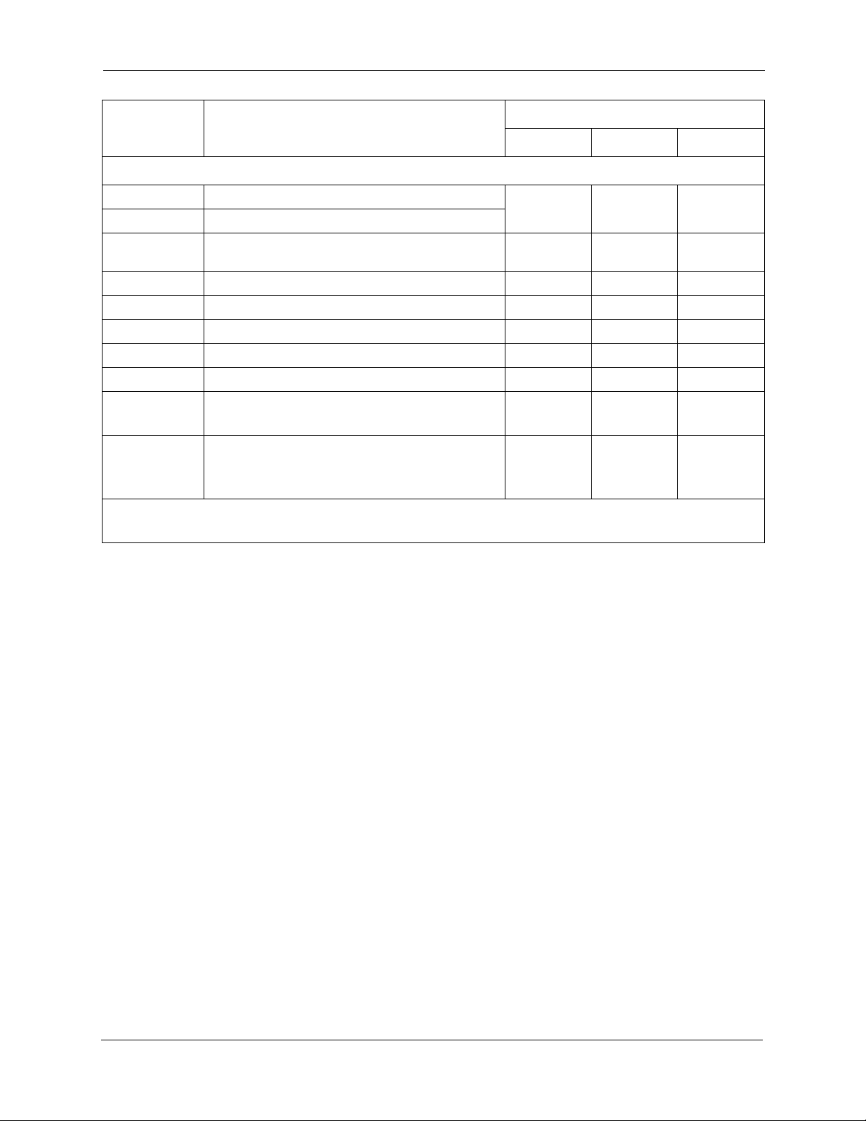
Printed Circuit Cards
The following table describes the printed circuit cards and other equipment
that can be used with the DBS. Also included are brief descriptions of each
card and the maximum number that can be installed in each cabinet.
Section 300-Installation
Table 2-2. Printed circuit card descriptions and maximums
Part No. Printed Circuit Cards and Other
Equipment
VB-43110 Cable kit for 2-system connection N/A N/A N/A
VB-43410 Call processor card (CPC-A)
VB-43412 Call processor card (CPC-AII)
VB-43420 Service circuit card (SCC-A)
VB-43421 Service circuit card (SCC-B)
VB-43431 DTMF signal receiver for 8 SLT lines
(MFR/8)
VB-43510A 4-port loop-start trunk card (L-TRK/4)
VB-43511A 8-port loop-start trunk card (L-TRK/8)
VB-43541 8-port Direct-inward-dialing trunk card
(DID)
VB-43531 8-port ground-start trunk card (G-TRK/8)
VB-43561 T1 Interface 1 1 1
Quantity
DBS 40 DBS 72 DBS 96
111VB-43411 Call processor card (CPC-B)
111
111
234
VB-43562 T1 MDF card 1 1 1
VB-43563 T1 Sync Unit 1 1 1
VB-43611 8-port digital extension card (DEC) 4 7 9
VB-43621A 8-port analog extension card (AEC) 3 4 4
Expansion Connectors
VB-43120 Trunk expansion connector
VB-43121 Extension expansion connector
Doorbox Equipment (Trunk)
VB-43701 2-port Door box adaptor 8* 12* 16*
VB-43705 Door box 16* 24* 32*
Doorbox Equipment (Extension)
VB-43711 1-port Extension-Based Door box adaptor 4 4 4
VB-43705 Door box 4 4 4
2-6 DBS Manual - Revised April 2000 DBS-2.3/9.2-300
111
Page 25
Section 300-Installation Chapter 2. System Overview
Part No. Printed Circuit Cards and Other
Equipment
DBS 40 DBS 72 DBS 96
Quantity
Optional Equipment
VB-43706 Remote Administration Interface (RAI-A)
111
VB-43707 Remote Administration Interface (RAI-B)
VB-43551 8-circuit Caller ID daughter board
1 per VB-
43511A AEC
1 per VB-
43511A A EC
1 per VB-
43511A AEC
VB-43130 Built-in system backup battery kit 1 1 1
VB-43709 Single Line Telephone Adaptor 8 14 18
VB-2089P SLT ringer box 1 1 1
VA-43703 4-line power failure unit 6 8 8
VB-43702 Off-premise extension adaptor 8 8 8
VB-43940 Standard Application processor interface
(API)
111
VB-43941 Telephony Services Kit (includes revised
API card, described in Telephone Services
111
Documentation)
* Note:
These maximums are based on overall trunk capacities and do not allow for trunks used
for outside lines.
DBS-2.3/9.2-300 DBS Manual - Revised April 2000 2-7
Page 26

Chapter 2. System Overview
Printed circuit cards are installed in dedicated slots in the DBS cabinet.
Table 2-3 shows the cards that can be installed in each slot. Figure 2-3 on
page 2-9 illustrates slot labels.
Table 2-3. Printed circuit package slot usage
Card Type Card Acceptable Slots
Section 300-Installation
Analog
Trunks
L-TRK/4
L-TRK/8
TRK or EC/TRK
G-TRK/8
DID/8
Digital Trunks T1/24 EC/TRK
Digital Lines DEC/8 EC 1-8 or EC/TRK
Analog Lines AEC/8 EC 2-8 or EC/TRK
Service
Circuits
SCC-A SCC
SCC-B
Processor Cards CPC-A CPC
CPC-B
CPC-AII
DTMF Circuits MFR/8 AUX1 or AUX2
CPC (See Note 1.)
Interface Cards API (1 or 2 Circuits) AUX1 or AUX2 (See Note 2.)
CBL-M CPC or AUX2 (See Note 3.)
CBL-S
Notes:
1. With one-cabinet systems, the MFR card can be installed in the AUX1 or AUX2 slot,
depending on whether an API card is used. With two-cabinet systems, placement of the MFR
cards differs according to the cable kit used. With Cable Kit Version 1.1, one MFR is installed
in the Master AUX1, and one MFR is installed in the Slave AUX1. With Cable Kit Version
1.2, both MFR cards are installed in the slave cabinet--one in the CPC slot and one in AUX1.
(See page 6-10 for instructions on installing MFR cards in double-cabinet systems.)
2. The API card is installed in AUX1 only when a CBL card is used.
3. Part VB-43110 includes both the CBL-M and CBL-S cards, as well as the required connecting cables. CBL-M is installed in the master cabinet, CBL-S in the slave cabinet.
2-8 DBS Manual - Revised April 2000 DBS-2.3/9.2-300
Page 27
Section 300-Installation Chapter 2. System Overview
s
Figure 2-3. Slot labels for printed circuit packages
Slot Label
(DBS 96)
TRK1 TR K2 TRK3 EC1 EC2 EC3 EC4 EC5 EC6 EC7 EC8 EC/TRK SCC CPC AUX1 AUX2
Processor Description
DBS call-processing is controlled by the Call Processor Card (CPC). Four
CPC models are available: CPC-A, CPC-B, CPC-AII, and CPC-EX. For a
complete list of hardware enha ncements a vailable with the CPC- B, CPC-AII ,
and CPC-EX, please see Appendix A and Appendix B, located in the back of
this manual. See the Appendix in Section 700 - Feature Operation for a
complete list of feature enhancements associated with each of these CPCs.
In most cases, the features provided with the DBS depend on the model and
software version of the CPC. Howeve r, the availability of some features also
depends on the model and version of the Service Circuit Card (SCC).
The following table shows some of the major differences between CPC/SCC
features. Other differences are noted throughout this manual when they apply
to specific installation instructions. For more details on the features provided
with each processor, see Feature Operation, Section 700.
Table 2-4. CPC/SCC features
Feature CPC/SCC Requirements
Double cabinet system CPC-B, Version 1.0 or greater plus SCC-B
DID CPC-B, Version 2.0 or greater plus SCC-B,
Version 1.2 or greater
T1 Interface CPC-B, Version 4.0 or greater plus SCC-B.
(The CPC-B must have BPU 1.3 or later. The
SCC-B ROM 1.3 or later is required if the CO
does not provide dial tone.)
DBS-2.3/9.2-300 DBS Manual - Revised April 2000 2-9
Page 28

Chapter 2. System Overview
Section 300-Installation
2-10 DBS Manual - Revised April 2000 DBS-2.3/9.2-300
Page 29

Chapter 3. Cabinet Installation
This chapter explains how to install and power up the cabinet. Before you
begin installation, be sure to read the “Requirements” chapter, which begins
on page 1-1.
This chapter covers the following topics::
Topic Page
Wall-Mounting the Cabinet 3-3
Grounding 3-5
Card Installation 3-6
Battery Backup 3-9
Key Phone Wall Mounting 3-13
DSLT Wall Mounting 3-15
System Initialization 3-17
Test Phone 3-18
DBS-2.3/9.2-300 DBS Manual - Revised April 2000 3-1
Page 30

3-2 DBS Manual - Revised April 2000 DBS-2.3/9.2-300
Page 31

Section 300-Installation Chapter 3. Cabinet Installation
r
Wall-Mounting the Cabinet
Guidelines
Caution:
tion.
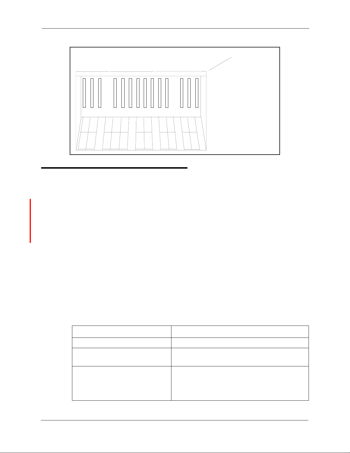
• The DBS is shipped with the cover installed to protect components. Before
wall-mounting the cabinet, remove the cover.
• Handle the cabinet carefully to avoid damage.
Installation
1. Remove the eight screws from the front and sides of the cabinet.
2. Take the front cover off by pulling it from the bottom and lifting it up.
3. Take the side covers off by sliding them up, then away.
Figure 3-1. Cover removal
Always turn the power switch
OFF
before beginning installa-
Screw s
Side C ove
Front C over
DBS-2.3/9.2-300 DBS Manual - Revised April 2000 3-3
Page 32

Chapter 3. Cabinet Installation
4. Attach the mounting brackets to the four corners of the back side of the
cabinet.
Figure 3-2. Cabinet mounting bracket
5. Install four screws in the wall studs according to the dimensions given in
Figure 3-3. (Note that the width dimension is different for the DBS 40.)
Metal M ounting
Bracket
Section 300-Installation
The screws are used to attach the mounting brackets to the wall. The
screws should protrude from the wall 5/16 in.
Figure 3-3. Cabinet wall-mounting
Screw
(# 1 0 -1 3 /4)
MainCabinet
Back Side
17 5/8"
(DBS 72, 96)
13 7/16"
(D BS 40)
Stud
Wall
22 3/16"
5/16"
6. Hang the cabinet on the wall by placing the mounting brackets over the
screws.
7. Tighten the screws to secure the cabinet.
3-4 DBS Manual - Revised April 2000 DBS-2.3/9.2-300
Page 33

Section 300-Installation Chapter 3. Cabinet Installation
Grounding
Guidelines
• Before grounding the DBS, read the “Lightning Protection/Grounding”
requirements beginning on page 1-6.
• The ground cable must be at least 18 AWG.
• Resistance to ground must be 10 Ohms or less.
Installation
1. Attach the ground cable to the ground screw on the front of the power
supply.
2. Connect the ground cable to the building ground.
Figure 3-4. Cabinet ground screw
TRK1 TRK2 TRK3 EC1 EC2 EC3 EC4 EC5 EC6 EC7 EC8 EC/TRK SCC CPC AUX 1 AUX2
CN11
CN1
CN12
SW 1
CN3
CN5 CN4
CN13
CN14
CN2
CN6
Ground Screw
DBS-2.3/9.2-300 DBS Manual - Revised April 2000 3-5
Page 34

Chapter 3. Cabinet Installation
Card Installation
Guidelines
Section 300-Installation
Caution:
Before handling printed circuit cards, discharge static electricity by grounding yourself. Static electricity can damage components.
Turn off the power before installiing. Installing cards with the power on
can damage components.
• Install the cards in the following order:
- TRK
- DEC
- AEC or API
- SCC
- CPC
- MFR or CBL
• If you are installing a CPC-A or CPC-AII card with an SCC-B card, set
SW4 to “Mode A.” The default setting is “Mode B,” which specifies that
CPC-B is used.
Figure 3-5. SCC-B Switch 4
ModeB
(C P C -B
CPC-EX)
SCC -B Card
3-6 DBS Manual - Revised April 2000 DBS-2.3/9.2-300
ModeA
(C P C -A
CPC-AII)
SW 4
Page 35

Section 300-Installation Chapter 3. Cabinet Installation
• Before installing the CPC card, determine if the DBS will be used as a
KSU or PBX.
To use it as a PBX, cut Strap S1 on the CPC.
Cutting this
strap allows use of pooled trunks as opposed to line appearances.
Figure 3-6. CPC Strap S1
CutS1 forPooled Trunks (PBX Operation)
Do NotCutS1 forLine Appearances(KSU O peration)
S1
CPC-AIIor
CPC-B
• Install cards only in their dedicated slots. The slot type is marked on the
cabinet directly above each slot.
DBS-2.3/9.2-300 DBS Manual - Revised April 2000 3-7
Page 36

Chapter 3. Cabinet Installation
Installation
1. With the lettering on the card pointed up, position the card within the slot
guides. (See Figure 3-7.)
2. Hold the card on the top and bottom edges with both hands and carefully
push the card into the slot.
3. When the connector at the far end of the card touches the corresponding
connector on the backplane, press the card in until it is firmly seated.
Figure 3-7. Printed circuit card installation
TRK 1 TRK 2 TR K3 EC1 EC2 EC3 EC4 EC5 EC 6 EC7 EC 8 EC/ TRK SCC CPC AU X1 AUX2
Section 300-Installation
Slot Label
Connector
Card
Label
Guide
TRK TRK
The M FR cardcanbeinstalled inthe CPC s lotofslav e cabinets.
*
TRK
*
EC EC EC EC EC EC EC
EC
TRK
or
T1
or
EC
SCC
CPC
or
MFR#
MFR
or
API
API
or
CBL
or
MFR
3-8 DBS Manual - Revised April 2000 DBS-2.3/9.2-300
Page 37

Section 300-Installation Chapter 3. Cabinet Installation
Battery Backup
Guidelines
• The DBS 40 uses two 12-volt batteries; the DBS 72 and 96 use four 6-volt
batteries or two 12-volt batteries. The following table includes the part
numbers for the battery packages.
Table 3-1. Battery backup packages for the DBS 40, 72, and 96
System Battery Backup Part No.
DBS 40 VB-43130 (some systems may be
equipped with VB-2450A-2P)
DBS 72 and 96 VB-43130 (some systems may be
equipped with VB-2650-2P)
• The backup batteries are connected in a series circuit, using cables
provided with the DBS.
• With maximum traffic, the backup batteries last up to 40 minutes for the
DBS 40 and 72, and up to 30 minutes for the DBS 96.
• The backup batteries should be replaced about every 3 years.
THE PRODUCT YOU HAVE PURCHASED MAY CONTAIN SEALED LEAD
ACID BATTERIES WHICH ARE RECYCLABLE. AT THE END OF THEIR
USEFUL LIFE, UNDER VARIOUS STATE AND LOCAL LAWS, IT IS ILLEGAL
TO DISPOSE OF THESE BATTERIES INTO YOUR MUNICIPLE WASTE
STREAM. PLEASE CALL 1-800-SAV-LEAD FOR INFORMATION ON HOW TO
RECYCLE THESE BATTERIES.
DBS-2.3/9.2-300 DBS Manual - Revised 5/22/97 3-9
Page 38

Chapter 3. Cabinet Installation
Installation for the DBS 40
1. Place one battery in the top tray of the battery compartment, the other
battery in the bottom tray.
Figure 3-8. Battery location, DBS 40
Section 300-Installation
Batteries
CN11
CN3
CN5
CN12
CN1
EC2 EC3EC1 SC CTRK1 CPC AUX2EC/TRK AUX1
CN4
CN2
CN15
CN1
CN6
2. Connect the positive cable (red) to the + terminal of the top battery.
3. Connect the connecting cable (white) to the - terminal of the top battery.
4. Connect the negative cable (blue) to the - terminal of the bottom battery.
5. Connect the connecting cable (white) from the top battery to the +
terminal on the bottom battery.
3-10 DBS Manual - Revised April 2000 DBS-2.3/9.2-300
Page 39

Section 300-Installation Chapter 3. Cabinet Installation
y
Installation for the DBS 72 and 96
1. Slide the battery compartment out and place the batteries inside the tray.
Figure 3-9. Battery tray, DBS 72 and 96
Remove Screws
and Slide B atter
Tr ay O ut
2. Connect the positive cable (red) to the + terminal on the first battery.
3. Connect the negative cable (blue) to the - terminal on the last battery.
4. Connect the remaining positive and negative terminals with the white
connection cables, as shown in Figure 3-10.
DBS-2.3/9.2-300 DBS Manual - Revised April 2000 3-11
Page 40

Chapter 3. Cabinet Installation
n
Figure 3-10. Battery pack connection, DBS 72 and 96
Red C onnection Cable
Back Positive
+
-
+
-
-
Blue C onnection C able
FrontNegative
Four 6-V oltB atteries
(O ld e r V e rs io n )
V B -2650-2P
Section 300-Installation
+
+
-
White
Connection
Cables
Blue C onnection C able
FrontN egative
T w o 1 2 - V o l t B a tte ri e s
(N ew er V ersion)
+
-
-
V B -43130
Red C onnection Cable
Back Positive
+
White
Connectio
Cables
3-12 DBS Manual - Revised April 2000 DBS-2.3/9.2-300
Page 41

Section 300-Installation Chapter 3. Cabinet Installation
Key Phone Wall Mounting
DBS key phones can be modified for wall mounting by reversing the wallmount adaptor on the bottom of the phone. The wall-mount adaptor includes a
small hole for attaching the phone to a screw inserted in the wall.
1. Place the bottom edge of the telephone on a desk or other hard surface.
2. Press the wall-mount adaptor down until it detaches from the phone
(Figure 3-11).
Figure 3-11. Wall-mount adaptor removal
Wall-Mount
Adaptor
DBS-2.3/9.2-300 DBS Manual - Revised April 2000 3-13
Page 42

Chapter 3. Cabinet Installation
3. Turn the wall-mount adaptor around and re-attach it to the phone.
Figure 3-12. Wall-mount adaptor replacement
Wall-M ount
Adaptor
Section 300-Installation
4. Remove the handset guide with a small screwdriver, turn it over, and
reinsert it into the phone.
Figure 3-13. Handset guide insertion for wall-mounting, key phone
3-14 DBS Manual - Revised April 2000 DBS-2.3/9.2-300
Page 43

Section 300-Installation Chapter 3. Cabinet Installation
DSLT Wall Mounting
Digital Single-Line Telephones (DSLTs) can be modified for wall mounting
by removing the desk stand and mounting it on the bottom of the phone. The
back of the DSL T and the desk stand include slots for attaching the phone to a
screw inserted in the wall.
1. Press the stand releases in toward the middle of the phone to release the
desk stand (Figure 3-14).
Figure 3-14. Desk stand removal for DSLT wall mounting
Desk
Stand
Stand
Releases
DBS-2.3/9.2-300 DBS Manual - Revised April 2000 3-15
Page 44

Chapter 3. Cabinet Installation
2. Attach the desk stand to the bottom of the phone by aligning the tabs and
tab guides and sliding it into place (Figure 3-15).
Figure 3-15. Desk stand attachment for DSLT wall mounting
Guides
Tab
Tabs
Section 300-Installation
3. Remove the handset guide with a small screwdriver, turn it over, and
reinsert it into the phone.
Figure 3-16. Handset guide insertion for wall-mounting, DSLT
3-16 DBS Manual - Revised April 2000 DBS-2.3/9.2-300
Page 45

Section 300-Installation Chapter 3. Cabinet Installation
System Initialization
1. Confirm that the DBS power switch is
2. Plug the power cord into a dedicated 120V 15 amp AC wall outlet.
Note:
A surge protector should be installed on the power cord.
3. Set SW1 on the CPC card to RAMCLR (RAM Clear).
Figure 3-17. CPC memory clear switch
TRK1 TRK2 TR K3 EC1 EC2 EC3 EC4 EC5 EC6 EC7 EC8 EC/ TRK SCC CPC AU X1 AUX2
OFF
.
STATUS
LED
SW 1
RAM H O LD
RAM C LR
4. Turn the power switch on.
As the system loads, the bottom LED lamp on the CPC card will flash.
5. Once the bottom LED lamp on the CPC card stops flashing, set SW1 on
the CPC to RAMHOLD.
DBS-2.3/9.2-300 DBS Manual - Revised April 2000 3-17
Page 46

Chapter 3. Cabinet Installation
Test Phone
Guidelines
• The test terminal (CN3) on the DBS Connector Panel can be used to
connect a display phone for programming.
The test terminal can be used for initial programming before extension
cabling is completed.
• The test terminal is turned on by flipping SW1 on the Connector Panel to
the “Test” position. When SW1 is in the test position, extension ports 7
and 8 are connected through the test terminal. When SW1 is not in the test
position, extension ports 7 and 8 are connected through the MDF.
Section 300-Installation
Installation
Note:
the phones connected to ports 7 and 8 can be taken out of service.
• A DSS/72 can be connected to the display phone for text entry. Port 7 must
be assigned as extension 101 and the DSS/72 must be assigned as
telephone type 13 for the DSS/72 to operate.
1. Connect the telephone and DSS (optional) to CN3 on the Connector
2. Set SW1 to “Test.”
3. When programming is completed, set SW1 back to “ST.”
Before using the test terminal on a DBS that is operational, be sure
Panel. (See Figure 3-18 on page 3-19.)
3-18 DBS Manual - Revised April 2000 DBS-2.3/9.2-300
Page 47

Section 300-Installation Chapter 3. Cabinet Installation
Figure 3-18. Test telephone connection
Tes tPhone DSS C onsole
Panasonic Panasonic
Note:Port7mustbe
assigned as extension
789
1
!
10 11 12
25
34
DEF
ABC
2
1
3
GHI
JKL6MNO
4
5
PRS
TUV9WXY
7
8
OPER
0
#
6
ANSW ER RELEASE
101 and the D SS/72
assigned as telephone
type13forthe D SS/72
tooperate.
SW 1
ST TEST
ST=Ports7and8
are conne c ted through
the M D F
TEST=Ports7and8
are conne c ted through
CN3
Two-C onductor
Cable(Port7)
CN11
CN1
CN12
Two-C onductor
Cable(Port8)
CN3
To the
telephone
CN5
CN13
CN4
CN14
CN3
To the
D SS/72
CN2
CN15
CN1
DBS-2.3/9.2-300 DBS Manual - Revised April 2000 3-19
Page 48

Chapter 3. Cabinet Installation
Section 300-Installation
3-20 DBS Manual - Revised April 2000 DBS-2.3/9.2-300
Page 49

Chapter 4. Trunks and Lines
This chapter describes trunk and line installation. Some peripheral equipment
also requires trunk and/or line interfaces (for example, door phones or power
failure units). See Chapter 5 for instructions on connecting peripheral
equipment through trunks or lines.
This chapter covers the following topics::
Topic Page
Trunks 4-3
Loop-Start Trunks 4-7
Ground Start and DID Trunks 4-9
T1 Interface 4-11
Lines 4-31
Analog Extensions 4-37
Digital Extensions 4-41
DSS/72 4-41
EM/24 4-43
Trunk and Line Expansion 4-44
DBS-2.3/9.2-300 DBS Manual - Revised April 2000 4-1
Page 50

4-2 DBS Manual - Revised April 2000 DBS-2.3/9.2-300
Page 51

Section 300-Installation Chapter 4. Trunks and Lines
Trunks
Trunk Connectors
Each DBS cabinet is provided with one main trunk connector, labeled CN1.
In addition, a trunk expansion connector (VB-43120) can be added to the
DBS to provide eight additional trunk connections. (The trunk expansion
connector is also labeled CN1.)
Figure 4-1 shows the maximum number of trunks that can be connected when
both trunk connectors are used with a DBS 96.
Figure 4-1. DBS trunk connections (DBS 96)
CN11
MainTrunkC onnector
CN12
CN1
CN3
CN5
CN13
CN4
CN14
CN15
CN1
CN2
Expa nsion Trunk C onnector
(V B -43120)
MDF
Trunk Ports
1-24
CO
Trunk Ports
25 -32
DBS-2.3/9.2-300 DBS Manual - Revised April 2000 4-3
Page 52

Chapter 4. Trunks and Lines
The number of trunks that can be connected through the main trunk connector
depends on the type of system you have and the number of trunk cards
installed. Table 4-1 shows the main trunks and expansion trunks available
with each system type. Chapter 6 includes trunk maximums for two-cabinet
systems.
Table 4-1. Main trunks and expansion trunks provided with each system type
System Type Main Trunk Numbers Expansion Trunk Numbers
DBS 40 1-8 9-16
DBS 72 1-16 17-24
DBS 96 1-24 25-32
Trunk Connector Pinouts
Table 4-2 includes pinouts and color codes for the main trunk connector.
Table 4-3 shows pinouts and color codes for the trunk expansion connector.
Section 300-Installation
Instructions on installing the expansion connector begin on 4-44.
4-4 DBS Manual - Revised April 2000 DBS-2.3/9.2-300
Page 53

Section 300-Installation Chapter 4. Trunks and Lines
Table 4-2. Pinouts and trunk numbers for the main trunk connector.
Trunk Slot
TRK1
(DBS 40,
DBS 72,
DBS 96)
TRK2
(DBS 72,
DBS 96)
TRK3
(DBS 96 only)
1. Trunks connections for a trunk card installed in the EC/TRK slot appear on the Trunk Port Expansion connector
as described on the next page.
1
Color Code Pin No. Desig. Function
WH-BL
BL-WH
WH-OR
OR-WH
WH-GN
GN-WH
WH-BR
BR-WH
WH-SL
SL-WH
RD-BL
BL-RD
RD-OR
OR-RD
RD-GN
GN-RD
RD-BR
BR-RD
RD-SL
SL-RD
BK-BL
BL-BK
BK-OR
OR-BK
BK-GN
GN-BK
BK-BR
BR-BK
BK-SL
SL-BK
YL-BL
BL-YL
YL-OR
OR-YL
YL-GN
GN-YL
YL-BR
BR-YL
YL-SL
SL-YL
VI-BL
BL-VI
VI-OR
OR-VI
VI-GN
GN-VI
VI-BR
BR-VI
VI-SL
SL-VI
26
1
27
2
28
3
29
4
30
5
31
6
32
7
33
8
34
9
35
10
36
11
37
12
38
13
39
14
40
15
41
16
42
17
43
18
44
19
45
20
46
21
47
22
48
23
49
24
50
25
10T
10R
11T
11R
12T
12R
13T
13R
14T
14R
15T
15R
16T
16R
17T
17R
18T
18R
19T
19R
20T
20R
21T
21R
22T
22R
23T
23R
24T
24R
Not used
1T
1R
2T
2R
3T
3R
4T
4R
5T
5R
6T
6R
7T
7R
8T
8R
9T
9R
Trunk 1
Trunk 2
Trunk 3
Trunk 4
Trunk 5
Trunk 6
Trunk 7
Trunk 8
Trunk 9
Trunk 10
Trunk 11
Trunk 12
Trunk 13
Trunk 14
Trunk 15
Trunk 16
Trunk 17
Trunk 18
Trunk 19
Trunk 20
Trunk 21
Trunk 22
Trunk 23
Trunk 24
DBS-2.3/9.2-300 DBS Manual - Revised April 2000 4-5
Page 54

Chapter 4. Trunks and Lines
Table 4-3. Pinouts and trunk numbers for trunk expansion connector CN1
Section 300-Installation
Trunk Slot Color
Code
EC/TRK WH-BL
BL-WH
WH-OR
OR-WH
WH-GN
GN-WH
WH-BR
BR-WH
WH-SL
SL-WH
RD-BL
BL-RD
RD-OR
OR-RD
RD-GN
GN-RD
Pin
No.
1
26
1
27
2
28
3
29
4
30
5
31
6
32
7
33
8
Desig. Trunk Assignments According to
System Type
DBS 40 DBS 72 DBS 96
1T
1R
2T
2R
3T
3R
4T
4R
5T
5R
6T
6R
7T
7R
8T
8R
Trunk
9
Trunk
10
Trunk
11
Trunk
12
Trunk
13
Trunk
14
Trunk
15
Trunk
16
1. Only the first 8 pairs on the trunk expansion connector are used.
Trunk
17
Trunk
18
Trunk
19
Trunk
20
Trunk
21
Trunk
22
Trunk
23
Trunk
24
Trunk
25
Trunk
26
Trunk
27
Trunk
28
Trunk
29
Trunk
30
Trunk
31
Trunk
32
4-6 DBS Manual - Revised April 2000 DBS-2.3/9.2-300
Page 55

Section 300-Installation Chapter 4. Trunks and Lines
Loop-Start Trunks
Guidelines
• Two versions of the loop-start trunk are available: the four-port version
(VB-43510) and the eight-port version (VB-43511).
• The following procedure covers loop-start trunk installation using the main
trunk connector. For instructions on using the expansion trunk connector,
see “Trunk and Line Expansion” on page 4-44
• For pinouts and color codes for the main trunk connector, see Table 4-2 on
page 4-5.
Installation
Installation without Caller ID
1. If installing VB-43511A Loop Start Card:
a. Remove the cover from the L-TRK card (VB-43511A).
b. Set the all option switches to ON as shown in Figure 4-2.
c. Replace the cover on the L-TRK card (VB-43511A).
Figure 4-2. L-TRK Card Strap J1 and Switch Locations
SW2
ON ON ON ON
TK2 TK3 TK4 TK5 TK6 TK7 TK8
TK1
ON ON ON ON
SW1 SW3
SW4 SW6 SW8
SW5
SW7
J1
Strap J1
mustbe
cut to
receive
Caller ID
ON
L-TRK Card
(VB-43511A)
ON
When a Caller ID Card Is Installed,
Set All Switches to the
When No C aller ID C ard Is Installed,
Set A ll Switch e s to th eONPosition
OFF
Position
DBS-2.3/9.2-300 DBS Manual - Revised April 2000 4-7
Page 56

Chapter 4. Trunks and Lines
2. Install the loop-start trunk in a trunk slot.
3. Use a standard 50-pin cable to connect the trunks from the MDF to the
main trunk connector CN1.
Installation with Caller ID
1. Remove the cover from the L-TRK card (VB-43511A). This cover should
be set aside since it cannot be reinstalled with a Caller ID Board installed.
2. Cut strap J1 on the L-TRK card as shown in Figure 4-2.
3. Set switches SW1 through SW8 on the L-TRK card (VB-43511A) to
OFF.
IMPORTANT: When caller ID is used, you must correctly set the switches to prevent possible
damage to the L-TRK card.
Section 300-Installation
4. Attach the Caller ID card to the L-TRK card.
Figure 4-3. Attaching Caller ID Card to the L-TRK Card
L-TRK Card
(VB-43511A)
Caller
ID B oard
(VB-43551)
5. Install the L-TRK card in a trunk slot.
6. Use a standard 50-pin cable to connect the trunks from the MDF to the
main trunk connector CN1.
4-8 DBS Manual - Revised April 2000 DBS-2.3/9.2-300
Page 57

Section 300-Installation Chapter 4. Trunks and Lines
Ground Start and DID Trunks
Guidelines
• The following procedure covers ground-start (VB-43531) and DID (VB-
43541) installation using the main trunk connector. For instructions on
using the expansion trunk connector, see “Trunk and Line Expansion” on
page 4-44.
• For pinouts and color codes for the main trunk connector, see Table 4-2 on
page 4-5.
• Each circuit on the ground-start trunk card can be used as either a loopstart or ground-start trunk. By default, all circuits on the ground-start trunk
are assigned as loop start.
• The ground-start trunk card requires CPC-B Version 1.0 or higher.
• The DID card requires CPC-B (Version 2.0 or higher) and SCC-B
(Version 1.2 or higher).
• Both ground start and DID trunks require an external -48V floating output
power supply. The following table shows -48V power consumption for
one- and two-cabinet systems.
Table 4-4. -48V current consumption for ground-start and DID trunks
System Size Current Consumption
(Output voltage = 48 ± 4 V
Ripple voltage =
One-cabinet system 1 Amp
Two-cabinet system 2 Amps
• The following -48V floating output power supplies have been tested with
DBS ground-start and DID trunks.
Table 4-5. -48V power supplies tested with the DBS
Manufacturer Model Number Rating
Valcom VP-2048B 2 Amps
Tellabs 81-8002 2 Amps
±500
mVp-p)
• The following “Installation” section includes details on installing the -48V
power supply.
DBS-2.3/9.2-300 DBS Manual - Revised April 2000 4-9
Page 58

Chapter 4. Trunks and Lines
Installation
1. Install the G-TRK/8 or DID card in a trunk slot.
2. Connect the power supply by cabling the positive side to the SG
connector on CN2 (Figure 4-4).
Section 300-Installation
Note:
Use cables that are 18 AWG or larger to connect the power supply
to the DBS.
Figure 4-4. -48Vpower supply installation
CN11
CN12
CN1
CN3
CN5
CN13
SG
CN4
CN14
RG
SYN
CN15
CN2
CN1
CN2
RG +24V Z0GND C Z2BM Z1 Z3 RE2Z4 RE1-48V
-48V PowerS upply
Recom m end:
Tellabs-8001
Tellabs-8002
-
+
3. Ground the positive side of the -48V power supply to the building
ground.
Note:
cable must be 18 AWG or larger.
4. Install power-surge protectors between the wall outlet and the -48V
power supply.
5. Use a standard 50-pin cable to connect the trunks from the MDF to the
main trunk connector CN1.
6. Use a test set to verify the polarity of the trunk.
4-10 DBS Manual - Revised April 2000 DBS-2.3/9.2-300
Resistance to ground must be 10 Ohms or less, and the ground
Page 59

Section 300-Installation Chapter 4. Trunks and Lines
Connect the test set across the tip and ring of the trunk to be tested. With
the test set in the “monitor” position, apply ground to the ring side of the
trunk.
If you hear dial tone, the polarity of the trunk is okay, and you can switch
the test set to the “talk” mode to test the voice path.
If you do not hear dial tone, ground the tip side of the trunk. If you
receive dial tone when grounding the tip side, polarity is reversed.
T1 Interface
Guidelines
Read the following guidelines before beginning T1 installation. Installation
instructions begin on page 4-21.
Hardware Requirements
• The T1 requires the following DBS hardware.
Table 4-6. T1 Hardware requirements for single-cabinet systems
CPC-B 4.0 or
Higher
(VB-43411)
1
(See Note 1.)
Notes:
1. Version 1.3 or higher of the Bus Processor Unit (BPU) chip is required for T1.
2. An MFR card is required for DID/ DNIS if DTMF signalin g is used. If DID/DNIS is provided t hrough
DP signaling, an MFR card is not required.
3. SCC-B with ROM 1.3 or higher is required if the central office does not provide T1 dial tone.
SCC-B
(VB-43421)
1
(See Notes 2 and 3.)
T1 T r unk Card
(VB-43561)
111
T1 MDF Card
(VB-43562)
Sync Unit
(VB-43563)
DBS-2.3/9.2-300 DBS Manual - Revised April 2000 4-11
Page 60

Chapter 4. Trunks and Lines
Section 300-Installation
Table 4-7. T1 Hardware requirements for double-cabinet systems
SCC-B
T1
Location
T1 in the
Master
T1 in the
Slave
T1 in both
Master
and
Slave
Notes:
1. Version 1.3 of the Bus Processor Unit (BPU) chip is required for T1.
2. An MFR card is required for DID/DNIS if DTMF signaling is used. If DID/DNIS is provided through DP signaling, an MFR card is not required.
3. SCC-B with ROM 1.3 or later is required if the central office does not provide T1 dial tone.
4. Version 1.2 of the Cable K it is required for T1 .
CPC-B V4
(VB-43411)
(See Note
1.)
1 1 1110 1
1 11111 1
1 1221
(VB-
43421)
(See Notes
2 and 3.)
T1 Trunk
Card
(VB-
43561)
T1 MDF
Card
(VB-
43562)
Sync
Card
(VB-
43563)
T1 Cable
(VB-
43564)
Cable Kit
(VB-43110)
(See Note
11
4.)
• The T1 trunk card must be installed in the “EC/TRK” slot.
• The installer
must
provide a Channel Service Unit (CSU) that complies
with FCC Part 15 and Part 68. The CSU is installed between the DBS and
the public network. The CSU provides alarm, diagnostic, and monitoring
functions, as well as network protection.
The CSU must be compatible with the framing for mat (SF or ESF ) that is
provided by the public network.
Maximums
• One T1 card can be installed per cabinet.
• The number of T1 cards that can be installed in double-cabinet systems
depends on the sizes of the connected systems. Table 4-12 on page 4-15
shows T1 maximums for double-cabinet systems.
Note:
The DBS 72 + DBS 40 combination does not support T1.
4-12 DBS Manual - Revised April 2000 DBS-2.3/9.2-300
Page 61

Section 300-Installation Chapter 4. Trunks and Lines
Table 4-8. T1 slot usage for two-cabinet systems
System Size EC/TRK Slot Usage for T1
Master Slave
DBS 40 + DBS 40 No Yes
DBS 72 + DBS 40 No No
DBS 72 + DBS 72 No Yes
DBS 96 + DBS 40 Yes Yes
DBS 96 + DBS 72 Yes Yes
DBS 96 + DBS 96 Yes Yes
• Fractional T1 can be used when fewer than 24 T1 trunks are needed.
Fractional T1 allows you to use only a portion of the 24 channels provided
on the T1 card.
• Though each T1 Interface provides 24 trunk channels, T1 trunks do not
increase the overall trunk capacity of the DBS. Each T1 channel subtracts
from the total number of analog trunks that can be installed.
• With CPC-B earlier than 5.00, the number of analog trunks that can be
used with Fractional T1 are always decremented in quantities of 8.
For example, if you are installing a T1 in a DBS 96 and you only want to
use 12 T1 channels, the logical number of analog trunks that would be
available is 20 (32 - 12 = 20).
The number of analog trunks must be decremented in quantities of 8, the
actual number of analog trunks that can be used is 16:
(32 total trunks - 16 (two 8-trunk increments) = 16.)
Tables 4-9 through 4-11 show the possible combinations of analog and
digital trunks assignments based on system size.
The trunk numbering shown in these tables is determined by backplane
trunk port assignments. Therefore, the numbering cannot be changed.
• With CPC-B 5.00 and higher and the VB-43511A Loop Start Trunk Card,
the number of analog trunks that can be used with Fractional T1 are
decremented in quantities of 1.
Note:
Analog trunks are numbered beginning with “1.” T1 trunk channels
are numbered beginning with the highest trunk channel used.
DBS-2.3/9.2-300 DBS Manual - Revised April 2000 4-13
Page 62

Chapter 4. Trunks and Lines
Trunk Assignments for Single-Cabinet Systems
• Programming is not required to associate trunk ports with slot locations.
However, you must use programming to specify that a combination of T1
and analog trunks are installed, and you must also specify how many T1
channels are used.
Table 4-9. T1 and analog trunk assignments, DBS 40
Section 300-Installation
Trunk
Number
Fractional T1
using 16 Channels
1 T1 channel 16 Analog trunk 1
↓↓ ↓
8 T1 channel 9 Analog trunk 8
9 T1 channel 8 T1 channel 8
↓↓ ↓
16 T1 channel 1 T1 channel 1
Note:
Since the DBS 40 supports a maximum of 16 trunks, all 24 chan-
nels of the T1 cannot be used.
Table 4-10. T1 and analog trunk assignments, DBS 72
Trunk
24-Channel T1 Fractional T1
Number
1 T1 channel 24 Analog trunk 1 Analog trunk 1
↓↓↓↓
8 T1 channel 17 Analog trunk 8 Analog trunk 8
using 16
Channels
Fractional T1
using 8 Channels
Fractional T1
using 8 Channels
9 T1 channel 16 T1 channel 16 Analog trunk 9
↓↓↓↓
16 T1 channel 9 T1 channel 9 Analog trunk 16
17 T1 channel 8 T1 channel 8 T1 channel 8
↓↓↓↓
24 T1 channel 1 T1 channel 1 T1 channel 1
4-14 DBS Manual - Revised April 2000 DBS-2.3/9.2-300
Page 63

Section 300-Installation Chapter 4. Trunks and Lines
Table 4-11. T1 and analog trunk assignments, DBS 96
Trunk
Number
24-Channel T1 Fractional T1
using 16
Fractional T1
using 8 Channels
Channels
1 Analog trunk 1 Analog trunk 1 Analog trunk 1
↓↓↓↓
8 Analog trunk 8 Analog trunk 8 Analog trunk 8
9 T1 channel 24 Analog trunk 9 Analog trunk 9
↓↓↓↓
16 T1 channel 17 Analog trunk 16 Analog trunk 16
17 T1 channel 16 T1 channel 16 Analog trunk 17
↓↓↓↓
24 T1 channel 9 T1 channel 9 Analog trunk 24
25 T1 channel 8 T1 channel 8 T1 channel 8
↓↓↓↓
32 T1 channel 1 T1 channel 1 T1 channel 1
Trunk Assignments for Double-Cabinet Systems
• When T1 is used in a double-cabinet system, the number of T1 channels
that can be assigned in each cabinet depends on the master/slave
designation.
The following table shows the maximum number of T1 channels that can
be assigned in two-cabinet systems.
Table 4-12. Maximum T1 assignments for two-cabinet systems
System Size Master Slave
DBS 40 + DBS 40 8 analog trunks 16 T1 trunks
DBS 72 + DBS 72 16 analog trunks 24 T1 trunks
DBS 96 + DBS 40 24 T1 trunks
8 analog trunks
DBS 96 + DBS 72 24 T1 trunks
8 analog trunks
DBS 96 + DBS 96 24 T1 trunks
8 analog trunks
• Two-cabinet systems use the same trunk numbering scheme as singlecabinet systems. Analog trunks are numbered from “1” upward; T1 trunk
channels are numbered downward from the highest channel used.
16 T1 trunks
24 T1 trunks
24 T1 trunks
8 analog trunks
DBS-2.3/9.2-300 DBS Manual - Revised April 2000 4-15
Page 64

Chapter 4. Trunks and Lines
Section 300-Installation
Tables 4-13 through 4-17 show trunk numbering for two-cabinet systems
using the maximum number of T1 channels.
Table 4-13. T1 and analog trunk assignments, DBS 40 + 40 (16-channel fractional T1 in the slave)
Trunk Number Master Cabinet Slave Cabinet
1 Analog trunk 1
↓↓ N/A
8 Analog trunk 8
9 T1 channel 16
↓ N/A ↓
16 T1 channel 9
17 T1 channel 8
↓Ν/Α ↓
24 T1 channel 1
Table 4-14. T1 and analog trunk assignments, DBS 72 + DBS 72 (24-channel T1 in the slave)
Trunk Number Master Cabinet Slave Cabinet
1 Analog trunk 1
↓↓ N/A
8 Analog trunk 8
9 Analog trunk 9
↓↓ N/A
16 Analog trunk 16
17 T1 channel 24
↓Ν/Α ↓
24 T1 channel 17
33 T1 channel 16
↓Ν/Α ↓
40 T1 channel 9
41 T1 channel 8
↓Ν/Α ↓
48 T1 channel 1
4-16 DBS Manual - Revised April 2000 DBS-2.3/9.2-300
Page 65

Section 300-Installation Chapter 4. Trunks and Lines
Table 4-15. T1 and analog trunk assignments, DBS 96 + DBS 40 (24-channel T1 in the master; 16-
channel T1 in the slave)
Trunk Number Master Cabinet Slave Cabinet
1 Analog trunk 1
↓↓ N/A
8 Analog trunk 8
9 T1 channel 24
↓↓ N/A
16 T1 channel 17
17 T1 channel 16
↓↓ N/A
24 T1 channel 9
25 T1 channel 8
↓↓ N/A
32 T1 channel 1
33 T1 channel 16
↓Ν/Α ↓
40 T1 channel 9
41 T1 channel 8
↓Ν/Α ↓
48 T1 channel 1
DBS-2.3/9.2-300 DBS Manual - Revised April 2000 4-17
Page 66

Chapter 4. Trunks and Lines
Table 4-16. T1 and analog trunk assignments, DBS 96 + DBS 72 (24-channel T1 in the master; 24-
channel T1 in the slave)
Section 300-Installation
Trunk Number Master Cabinet Slave Cabinet
1 Analog trunk 1
↓↓ N/A
8 Analog trunk 8
9 T1 channel 24
↓↓ N/A
16 T1 channel 17
17 T1 channel 16
↓↓ N/A
24 T1 channel 9
25 T1 channel 8
↓↓ N/A
32 T1 channel 1
33 T1 channel 24
↓Ν/Α ↓
40 T1 channel 17
41 T1 channel 16
↓Ν/Α ↓
48 T1 channel 9
49 T1 channel 8
↓Ν/Α ↓
56 T1 channel 1
4-18 DBS Manual - Revised April 2000 DBS-2.3/9.2-300
Page 67

Section 300-Installation Chapter 4. Trunks and Lines
Table 4-17. T1 and analog trunk assignments, DBS 96 + DBS 96 (24-channel T1 in the master; 24-
channel T1 in the slave)
Trunk Number Master Cabinet Slave Cabinet
1 Analog trunk 1
↓↓ N/A
8 Analog trunk 8
9 T1 channel 24
↓↓ N/A
16 T1 channel 17
17 T1 channel 16
↓↓ N/A
24 T1 channel 9
25 T1 channel 8
↓↓ N/A
32 T1 channel 1
33 Analog trunk 1
↓Ν/Α ↓
40 Analog trunk 8
41 T1 channel 24
↓Ν/Α ↓
48 T1 channel 17
49 T1 channel 16
↓Ν/Α ↓
56 T1 channel 9
57 T1 channel 8
↓Ν/Α ↓
64 T1 channel 1
DBS-2.3/9.2-300 DBS Manual - Revised April 2000 4-19
Page 68

Chapter 4. Trunks and Lines
Installation
The following procedures provide step-by-step instructions for installing the
T1 Interface. The procedure that you should use depends on the type of
system you have and the number of T1s you are installing.
If you are installing ... Use this procedure...
A T1 in a single cabinet “Installing a T1 in a Single Cabi-
Section 300-Installation
net” (page 4-21)
One T1 in a double cabinet, with the
T1 located in the master
One T1 in a double cabinets, with the
T1 located in the slave
“Installing a T1 in a Single Cabinet” (page 4-21)
“Installing a T1 in a Double Cabinet with the T1 in the Slave”
(page 4-27)
T1s in both the master and slave “Installing a T1 in a Double Cabi-
net with T1s in the Master and
Slave” (page 4-27)
4-20 DBS Manual - Revised April 2000 DBS-2.3/9.2-300
Page 69

Section 300-Installation Chapter 4. Trunks and Lines
Installing a T1 in a Single Cabinet
The following instructions explain how to install a T1 in a single-cabinet
system. These instructions also apply when a T1 is installed in only the
master cabinet of a two cabinet system.
If only one T1 is installed in a two-cabinet system, it must be installed in the
cabinet specified in Table 4-8 on page 4-13.
Note:
The T1 Interface cannot be used for systems consisting of a DBS 72
connected to a DBS 40.
1. Check connector 4 (CN4) on the Sync Unit (VB-43563). Make sure that
Pins 2 and 3 are strapped. (See Figure 4-5.)
When Pins 2 and 3 are strapped, the Sync Unit synchronizes the DBS T1
card with the signaling provided by the public network.
Figure 4-5. Connector 4 (CN4) strapping, Sync Unit
CN3
CN1
1
CN2
CN4
3
Free N et
DBS-2.3/9.2-300 DBS Manual - Revised April 2000 4-21
Page 70

Chapter 4. Trunks and Lines
2. Attach the Sync Unit to the CPC-B card.
Section 300-Installation
Note:
Before attaching the Sync Unit, insert the three spacers provided
with the unit and remove the jumpers from CN2 of the CPC-B card.
Figure 4-6. T1 Sync Unit installation
4-22 DBS Manual - Revised April 2000 DBS-2.3/9.2-300
Page 71

Section 300-Installation Chapter 4. Trunks and Lines
3. Install the T1 MDF (main distribution frame) card in the top of the
cabinet as shown in Figure 4-7.
Figure 4-7. T1 MDF card installation
DBS-2.3/9.2-300 DBS Manual - Revised April 2000 4-23
Page 72

Chapter 4. Trunks and Lines
4. Set SW1 on the T1 card according to the following table.
These switch settings correspond to the distance between the DBS and the
CSU. To turn a switch on, flip it to the “up” position.
Table 4-18. Switch settings for SW1 on the T1 card
SW Distance from the DBS to the CSU
0 to 150 ft. 150-450 ft. 450-655 ft.
SW1 On Off Off
SW2 Off On Off
SW3 Off Off On
SW4 Off On Off
SW5 Off Off On
SW6 Off On Off
SW7 Off Off On
SW8 Not used Not used Not used
Section 300-Installation
5. Install the T1 card in the “EC/TRK” slot
6. Connect the Sync Cable from CN1 on the Sync Unit to CN5 on the T1
card.
Figure 4-8. Sync Unit and T1 connection, single-cabinet installation
TRK
DEC DEC
DEC DEC
DEC
DEC DEC
DEC T1
TRK
SyncCable
SCC
CPC
Sync.Unit
MFR
N
O
T
U
S
E
D
S.U.
CN1
CN5
7. Connect the cable attached to CN3 on the T1 MDF card to CN3 on the T1
card (Figure 4-10).
8. Using an RJ48 cable, connect CN1 on the T1 MDF card to the CSU
(Figure 4-10). The following illustration shows CN1 pinouts.
4-24 DBS Manual - Revised April 2000 DBS-2.3/9.2-300
Page 73

Section 300-Installation Chapter 4. Trunks and Lines
Figure 4-9. RJ48 pinouts, CN1 connector
Ti p1
Ring 1
Ti p
Ring
2
1
Ring 1
= Receive
=Transm it
Ti p1
Ring
NC
Ti p
CN1 (RJ 4 8 )
NC
8
FG
7
FG
DBS-2.3/9.2-300 DBS Manual - Revised April 2000 4-25
Page 74

Chapter 4. Trunks and Lines
e
9. Connect the ground cable from the T1 MDF card to the cabinet as shown
in Figure 4-10.
Figure 4-10. T1 cabinet connections, single-cabinet installation
Section 300-Installation
CN11
CN1
TRK1 TR K2 TRK3 EC1 EC2 EC3 EC4 EC5 EC6 EC7 EC8 EC/ TRK SCC CPC AUX1 AUX2
CN12
SW 1
CN3
CN5
CN13
CN4
CN14
CN1
CN2
CN6
CN3
T-1 L i ne
CSU
T- 1MDF
Ground Cabl
Sync Unit
CN3
CN1
T-1Card
CN5
Sync Cable
4-26 DBS Manual - Revised April 2000 DBS-2.3/9.2-300
Page 75

Section 300-Installation Chapter 4. Trunks and Lines
Installing T1 in a Double Cabinet with the T1 in the Slave
1. Install the Sync Unit in the master cabinet as described in Steps 1 and 2
under “Installation for a Single T1.”
2. Install a T1 MDF card in the slave cabinet. (See Step 3 on page 4-23.)
3. Set Switch 1 on the T1 card. (See Step 4 on page 4-24.)
4. Install a T1 card in the “EC/TRK” slot of the slave cabinet.
5. Connect the Sync Cable from CN1 on the Sync Unit to CN5 on the T1
card (Figure 4-11).
Note:
Part Number VB-43564 is used for the Sync Cable when a T1 is
installed only in the slave cabinet of a two-cabinet system.
6. At the slave cabinet, connect the cable attached to CN3 on the T1 MDF
card to CN3 on the T1 card (Figure 4-10).
7. Using an RJ48 ca ble, connect CN1 of the T1 MDF card to the CSU. (See
Figure 4-9 on page 4-25 for RJ48 pinouts.)
8. At the slave cabinet, connect the ground cable on the T1 MDF card as
shown in Figure 4-10 on page 4-26.
DBS-2.3/9.2-300 DBS Manual - Revised April 2000 4-27
Page 76

Chapter 4. Trunks and Lines
Figure 4-11. Sync cable connections, double-cabinet with a T1 in the slave
Section 300-Installation
Card
Label
TRK
Guide
Slave C abinet
TRK1 TR K2 TRK3 EC1 EC2 EC3 EC4 EC5 EC6 EC7 EC8 EC/TRKS CC CPC AUX1 AUX 2
DEC DEC
DEC DEC
DEC
DEC DEC
Master C abinet
TRK1 TR K2 TRK3 EC1 EC2 EC3 EC4 EC5 EC6 EC7 EC8 EC/TRKS CC CPC AUX1 AU X2
DEC
TRK
T- 1 M D F
Slot Label
Connector
T1
N
O
T
U
S
E
D
MFR
MFR
CBL
2
1
(S)
CN5
Interconnection
Cables
Card
Label
Guide
TRK
Note:
The num berofana log t runksthatc anbe
instal ledde pendsonhow m anyT1 cha nne lsare
use d.
DEC DEC
DEC DEC
DEC
DEC DEC
DEC
SCC
CPC
Sync.Unit
Sync
Cable
(VB -43564)
CBL
(M)
N
O
T
U
S
E
D
CN1
4-28 DBS Manual - Revised April 2000 DBS-2.3/9.2-300
Page 77

Section 300-Installation Chapter 4. Trunks and Lines
Installing T1 in a Double Cabinet with T1s in the Master and Slave
1. Install the Sync Unit in the master cabinet as described in Steps 1 and 2
under “Installation for a Single T1.”
2. Install a T1 MDF card in each cabinet. (See Step 3 on page 4-23.)
3. Set Switch 1 on the T1 cards. (See Step 4 on page 4-24.)
4. Install a T1 card in each “EC/TRK” slot.
5. Connect the Clock Sync Cable from CN4 on the master-cabinet T1 to
CN5 on the slave-cabinet T1, as shown in Figure 4-12.
Note:
Part Number VB-43564 is used for the Clock Sync Cable when
T1s are installed in the master and slave cabinets.
6. At the master cabinet, connect the Sync Cable from CN1 on the Sync
Unit to CN5 on the T1 card (Figure 4-12).
7. At each cabinet, connect the cable attached to CN3 on the T1 MDF card
to CN3 on the T1 card (Figure 4-10).
8. Using an RJ48 cable, connect CN1 of each T1 MDF card to a CSU. (See
Figure 4-9 on page 4-25 for RJ48 pinouts.)
9. For both cabinets, connect the ground cable from the T1 MDF card as
shown in Figure 4-10 on page 4-26.
DBS-2.3/9.2-300 DBS Manual - Revised April 2000 4-29
Page 78

Chapter 4. Trunks and Lines
Section 300-Installation
Figure 4-12. Clock sync cable and sync cable connections, double-cabinet installation
Card
Label
TRK
Guide
Slave Cabinet
TRK1 TRK2 TR K3 EC1 EC2 EC3 EC4 EC5 EC6 EC7 EC8 EC/TRK SCC CPC AUX1 AUX2
DEC DEC
DEC DEC
DEC
DEC D EC
MasterCabinet
TRK1 TRK2 TRK 3 EC1 EC2 EC 3 EC4 EC5 E C6 EC7 EC8 EC/TRKSCC CPC AUX1 AUX2
DEC
TRK
T- 1 M D F
Slot Label
Connector
T1
N
O
T
U
S
E
D
MFR
1
MFR
2
CBL
(S)
CN5
T- 1 M D F
Slot Label
Connector
Interconnection
Cables
Card
Label
Guide
TRK
Note:
Thenum berofana log t runk sthatc a nbe
instal led dependson how m anyT1 channe lsare
use d.
DEC DEC
DEC DEC
DEC
DEC DEC
DEC
T- 1
TRK
Sync
Cable
SCC
CPC
Sync .Unit
Clock Sync.
Cable
(VB -43564)
CBL
(M)
N
O
T
U
S
E
D
CN4
CN1
CN5
4-30 DBS Manual - Revised April 2000 DBS-2.3/9.2-300
Page 79

Section 300-Installation Chapter 4. Trunks and Lines
Lines
Extension Connector s
The number of extension ports that can be connected to your system depends
on the type of system you have. Figure 4-13 shows the maximum number of
extensions that can be connected to each system when the extension
expansion connector is used.
Table 4-1 summarizes the number of ports that can be used without the
extension expansion connector. Chapter 6 includes extension maximums for
two-cabinet systems.
Figure 4-13. DBS extension connections
CN11
CN1
CN12
CN5
CN4
CN3
Extension Ports
Extension Ports
CN14
CN13
Extension Ports
25 -32
or
49 -56
1-24
25 -48
CN2
CN15
CN1
To CN1 onthe Extension
Ex pans ion Connector
To
CN12
To
CN13
MDF
Extension Ex pans ion C onnector
VB-43121
Extension 25
DBS
Extension 32
Extension 1
Extension 24
Extension 25
Extension 48
40
DBS 72
and 96
Extension 49
or
Extension 56
DBS
72
To
CN14
Extension Ports
49 -72
Extension 49
Extension 72
DBS 96
only
DBS-2.3/9.2-300 DBS Manual - Revised April 2000 4-31
Page 80

Chapter 4. Trunks and Lines
Table 4-19. Extension ports provided with each system
System Type Extension Ports
(Not including the Expansion Connector*)
DBS 40 1-24
DBS 72 1-48
DBS 96 1-72
Section 300-Installation
*Note:
Extensions 65 to 72 on the DBS 96 use the EC/TRK slot, but they
do not require the extension expansion connector. If extensions 65 to 72 are
used, the trunk expansion connector cannot be used.
Extension Connector Pinouts
Tables 4-20 through 4-22 provide pinouts and color codes for extension
slots.Table 4-22 on page 4-35 provides pinouts and color codes for the
extension expansion connector.
Instructions on installing the expansion connector begin on 4-44.
4-32 DBS Manual - Revised April 2000 DBS-2.3/9.2-300
Page 81

Section 300-Installation Chapter 4. Trunks and Lines
Table 4-20. Pinouts and color codes for extension connector CN12
Extension Slot Color Code Pin No. Desig. Function
EC1
(DBS 40,
DBS 72,
DBS 96)
EC2
(DBS 40,
DBS 72,
DBS 96)
EC3
(DBS 40,
DBS 72,
DBS 96)
WH-BL
BL-WH
WH-OR
OR-WH
WH-GN
GN-WH
WH-BR
BR-WH
WH-SL
SL-WH
RD-BL
BL-RD
RD-OR
OR-RD
RD-GN
GN-RD
RD-BR
BR-RD
RD-SL
SL-RD
BK-BL
BL-BK
BK-OR
OR-BK
BK-GN
GN-BK
BK-BR
BR-BK
BK-SL
SL-BK
YL-BL
BL-YL
YL-OR
OR-YL
YL-GN
GN-YL
YL-BR
BR-YL
YL-SL
SL-YL
VI-BL
BL-VI
VI-OR
OR-VI
VI-GN
GN-VI
VI-BR
BR-VI
VI-SL
SL-VI
26
27
28
29
30
31
32
33
34
35
10
36
11
37
12
38
13
39
14
40
15
41
16
42
17
43
18
44
19
45
20
46
21
47
22
48
23
49
24
50
25
1T
1
2
3
4
5
6
7
8
9
1R
2T
2R
3T
3R
4T
4R
5T
5R
6T
6R
7T
7R
8T
8R
9T
9R
10T
10R
11T
11R
12T
12R
13T
13R
14T
14R
15T
15R
16T
16R
17T
17R
18T
18R
19T
19R
20T
20R
21T
21R
22T
22R
23T
23R
24T
24R
Not used
Extension Port 1
Extension Port 2
Extension Port 3
Extension Port 4
Extension Port 5
Extension Port 6
Extension Port 7
Extension Port 8
Extension Port 9
Extension Port 10
Extension Port 11
Extension Port 12
Extension Port 13
Extension Port 14
Extension Port 15
Extension Port 16
Extension Port 17
Extension Port 18
Extension Port 19
Extension Port 20
Extension Port 21
Extension Port 22
Extension Port 23
Extension Port 24
Note: Only digital ext ensions can be used in slot EC1. Port 1 is reserved for Attendant 1 and requires a Display Key Phone.
DBS-2.3/9.2-300 DBS Manual - Revised April 2000 4-33
Page 82

Chapter 4. Trunks and Lines
Table 4-21. Pinouts and color codes for extension connector CN13
Extension Slot Color Code Pin No. Desig. Function
EC4
(DBS 72,
DBS 96)
EC5
(DBS 72,
DBS 96)
EC6
(DBS 72,
DBS 96)
WH-BL
BL-WH
WH-OR
OR-WH
WH-GN
GN-WH
WH-BR
BR-WH
WH-SL
SL-WH
RD-BL
BL-RD
RD-OR
OR-RD
RD-GN
GN-RD
RD-BR
BR-RD
RD-SL
SL-RD
BK-BL
BL-BK
BK-OR
OR-BK
BK-GN
GN-BK
BK-BR
BR-BK
BK-SL
SL-BK
YL-BL
BL-YL
YL-OR
OR-YL
YL-GN
GN-YL
YL-BR
BR-YL
YL-SL
SL-YL
VI-BL
BL-VI
VI-OR
OR-VI
VI-GN
GN-VI
VI-BR
BR-VI
VI-SL
SL-VI
26
27
28
29
30
31
32
33
34
35
10
36
11
37
12
38
13
39
14
40
15
41
16
42
17
43
18
44
19
45
20
46
21
47
22
48
23
49
24
50
25
1
2
3
4
5
6
7
8
9
Not used
1T
1R
2T
2R
3T
3R
4T
4R
5T
5R
6T
6R
7T
7R
8T
8R
9T
9R
10T
10R
11T
11R
12T
12R
13T
13R
14T
14R
15T
15R
16T
16R
17T
17R
18T
18R
19T
19R
20T
20R
21T
21R
22T
22R
23T
23R
24T
24R
Section 300-Installation
Extension Port 25
Extension Port 26
Extension Port 27
Extension Port 28
Extension Port 29
Extension Port 30
Extension Port 31
Extension Port 32
Extension Port 33
Extension Port 34
Extension Port 35
Extension Port 36
Extension Port 37
Extension Port 38
Extension Port 39
Extension Port 40
Extension Port 41
Extension Port 42
Extension Port 43
Extension Port 44
Extension Port 45
Extension Port 46
Extension Port 47
Extension Port 48
4-34 DBS Manual - Revised April 2000 DBS-2.3/9.2-300
Page 83

Section 300-Installation Chapter 4. Trunks and Lines
Table 4-22. Pinouts and color codes for extension connector CN14
Extension Slot Color Code Pin No. Desig. Function
EC7
(DBS 96 Only)
EC8
(DBS 96 Only)
EC/TRK
(DBS 96 only)
WH-BL
BL-WH
WH-OR
OR-WH
WH-GN
GN-WH
WH-BR
BR-WH
WH-SL
SL-WH
RD-BL
BL-RD
RD-OR
OR-RD
RD-GN
GN-RD
RD-BR
BR-RD
RD-SL
SL-RD
BK-BL
BL-BK
BK-OR
OR-BK
BK-GN
GN-BK
BK-BR
BR-BK
BK-SL
SL-BK
YL-BL
BL-YL
YL-OR
OR-YL
YL-GN
GN-YL
YL-BR
BR-YL
YL-SL
SL-YL
VI-BL
BL-VI
VI-OR
OR-VI
VI-GN
GN-VI
VI-BR
BR-VI
VI-SL
SL-VI
26
27
28
29
30
31
32
33
34
35
10
36
11
37
12
38
13
39
14
40
15
41
16
42
17
43
18
44
19
45
20
46
21
47
22
48
23
49
24
50
25
1T
1
2
3
4
5
6
7
8
9
1R
2T
2R
3T
3R
4T
4R
5T
5R
6T
6R
7T
7R
8T
8R
9T
9R
10T
10R
11T
11R
12T
12R
13T
13R
14T
14R
15T
15R
16T
16R
17T
17R
18T
18R
19T
19R
20T
20R
21T
21R
22T
22R
23T
23R
24T
24R
Not used
Extension Port 49
Extension Port 50
Extension Port 51
Extension Port 52
Extension Port 53
Extension Port 54
Extension Port 55
Extension Port 56
Extension Port 57
Extension Port 58
Extension Port 59
Extension Port 60
Extension Port 61
Extension Port 62
Extension Port 63
Extension Port 64
Extension Port 65
Extension Port 66
Extension Port 67
Extension Port 68
Extension Port 69
Extension Port 70
Extension Port 71
Extension Port 72
Note:
The EC/TRK slot is wired to CN14 only in the DBS 96. In the DBS 40 and
72, a card placed in the EC/TRK slot must be wired to the expansion connector.
DBS-2.3/9.2-300 DBS Manual - Revised April 2000 4-35
Page 84

Chapter 4. Trunks and Lines
Table 4-23. Pinouts and color codes for extension expansion connector CN1
Section 300-Installation
Extension
Slot
EC/TRK WH-BL
Color
Code
BL-WH
WH-OR
OR-WH
WH-GN
GN-WH
WH-BR
BR-WH
WH-SL
SL-WH
RD-BL
BL-RD
RD-OR
OR-RD
RD-GN
GN-RD
Pin No. Desig. Extension Por t Assignments
According to System Type
DBS 40 DBS 72 DBS 96
26
1
27
2
28
3
29
4
30
5
31
6
32
7
33
8
1T
1R
2T
2R
3T
3R
4T
4R
5T
5R
6T
6R
7T
7R
8T
8R
Extension
Port 25
Extension
Port 26
Extension
Port 27
Extension
Port 28
Extension
Port 29
Extension
Port 30
Extension
Port 31
Extension
Port 32
Extension
Port 49
Extension
Port 50
Extension
Port 51
Extension
Port 52
Extension
Port 53
Extension
Port 54
Extension
Port 55
Extension
Port 56
Extension
Expansion
Required
instead)
No
Card
(uses
CN14
4-36 DBS Manual - Revised April 2000 DBS-2.3/9.2-300
Page 85

Section 300-Installation Chapter 4. Trunks and Lines
Analog Extensions
Guidelines
Installation
Note:
Alternatively, a Single Line Telephone Adaptor (SLTA, VB-43709) may be
used to support analog DTMF (2500 set) extensions. The SLTA converts up
to 4 digital ports to analog ports. See “Single Line Telephone Adaptor” on
page 5-34 for more information.
• An MFR card (VB-43431) is required when the AEC is used. The MFR
• The AEC also requires the SLT ringer box (VB-2089P).
1. Install the AEC cards in extension slots.
2. Install the MFR card in AUX1 or AUX2. If installing in a two-cabinet
3. Install the SLT Ringer Box as shown in Figure 4-14. Be sure to note the
Normally analog extensions are supported using the AEC (VB-43621).
card, which provides DTMF signals, includes eight circuits that are shared
among the analog extensions.
system, see Chapter 6 for specific information for installing MFR card(s).
differences between the DBS 40 Connector Panel and the Connector
Panel on the DBS 72 and 96.
DBS-2.3/9.2-300 DBS Manual - Revised April 2000 4-37
Page 86

Chapter 4. Trunks and Lines
Figure 4-14. SLT ringer box installation
Section 300-Installation
4-38 DBS Manual - Revised April 2000 DBS-2.3/9.2-300
Page 87

Section 300-Installation Chapter 4. Trunks and Lines
Ringer box installation with the DBS 72 and DBS 96
CN11
CN12
CN3
CN5
CN13
CN4
CN14
CN2
CN15
CN1
RG
SYN
SG
Ringer box installation with the DBS 40
CN11
CN3
CN12
CN5
CN4
CN15
CN2
CN6
CN1
RG +24V Z0GND C Z2BM Z1 Z3 RE2Z4 RE1-48V
CN2
+24V R G
RG
GND
SYN
(BRN)
(RED)
SLT R ingerBox
(VB-2089P )
CN1
SG
CN1
-48V
RG
SYN
RG
GND
CN2
+24V
MZ2C B Z1 Z3 RE2Z4 RE1
Z0
+24V
GND
(BRN)
SLT Ringer Box
(VB-2089P)
RG
RG
SYN
(RED)
DBS-2.3/9.2-300 DBS Manual - Revised April 2000 4-39
Page 88

Chapter 4. Trunks and Lines
4. Use a standard 50-pin cable to connect the extensions from the MDF to
the appropriate extension connector. (Refer to Tables 4-20 through 4-22
for extension pinouts.)
5. If you are installing a DBS 40 system, attach the EMI filter to the
amphenol cable as shown in Figure 4-15.
Figure 4-15. EMI filter installation (DBS 40 only)
EMI
Filter
Section 300-Installation
31/2"
4-40 DBS Manual - Revised April 2000 DBS-2.3/9.2-300
Page 89

Section 300-Installation Chapter 4. Trunks and Lines
Digital Extensions
The following instructions explain how to connect digital extensions. These
instructions apply for key phones and Digital Single-Line Telephones
(DSLTs). Special instructions are provided for installing the DSS/72 and
EM24 terminals, which connect to digital phones.
1. Install the DEC cards in extension slots.
2. Use a standard 50-pin cable to connect the extensions from the MDF to
the appropriate extension connector, as shown in Figure 4-13 on page 4-
31. (Refer to Tables 4-20 through 4-22 for extension pinouts.)
3. If you are installing a DBS 40, attach the EMI filter to the amphenol
cable, as shown in Figure 4-15.
DSS/72
Guidelines
• The DSS/72 (VB-43320) is a 72-key console that can be attached to the
attendant phone. It provides direct station selection and busy lamp fields
for internal lines. The DSS/72 can also be used for text assignment.
• When the attendant feature package (VB-43330) is installed (CPC-B
Version 2.0 to 4.0 only), the DSS/72 can be used as an Attendant Console.
The Attendant Console provides station monitoring and call transfer by
name for large systems, even if a large display phone is not used. For a
detailed description of the differences between the standard DSS/72 and a
DSS/72 configured as an Attendant Console, see Feature Operation,
Section 700. For instructions on using the Attendant Console, see the
Attendant Console User Guide, Section 760.
• Up to two DSS/72s or one Attendant Console can be assigned to attendant
phones 1 and 2. Attendant phones 3 and 4 can each have one Attendant
Console assigned, but neither can have a DSS/72.
• If more than one DSS/72 is assigned to an attendant phone, only one of the
DSS/72s can be cabled from the same wall jack as the attendant phone.
Additional DSS/72s must be cabled from separate wall jacks.
• The DSS/72 comes with a mounting bracket, screws, and a two-conductor
cable for attaching the DSS to the key phone.
DBS-2.3/9.2-300 DBS Manual - Revised April 2000 4-41
Page 90

Chapter 4. Trunks and Lines
Installation
1. Attach the DSS/72 to the key phone using the mounting plate and the four
screws.
2. Connect the DSS to the key phone using the two-conductor cable.
3. Connect the DSS to the wall jack using a four-conductor cable.
4. Connect the four wires from the key phone and DSS to the MDF.
Figure 4-16. DSS/72 connection using one cable with two pairs.
Section 300-Installation
4-42 DBS Manual - Revised April 2000 DBS-2.3/9.2-300
Page 91

Section 300-Installation Chapter 4. Trunks and Lines
EM/24
Guidelines
• The EM/24 (VB-43310) provides 24 flexible function (FF) keys. It can be
attached to any key phone.
• The EM/24 comes with a mounting bracket, screws, and a two-conductor
cable for attaching it to a key phone.
Installation
1. Attach the EM /24 to the key phone using the mounting pl ate and the four
screws, as shown in Figure 4-17.
2. Connect the EM/24 to the key phone using the two-conductor cable.
3. Connect the EM/24 to the wall jack using a four-conductor cable.
4. Connect the four wires from the key phone and EM/24 to the MDF
connector.
Figure 4-17. EM/24 connection using one cable with two pairs
DBS-2.3/9.2-300 DBS Manual - Revised April 2000 4-43
Page 92

Chapter 4. Trunks and Lines
Trunk and Line Expansion
Guidelines
• The EC/TRK slot can be used for a trunk or extension card.
• Different expansion connectors are used for trunks and extensions:
Expansion connector Part No.
Trunk expansion connector VB-43120
Extension expansion connector VB-43121
Section 300-Installation
Installation
Note:
the EC/TRK slot for an extension card. The DBS 96 uses connector CN14
to accommodate an extension card in the EC/TRK slot. Table 4-22 on
page 4-35 shows the pinouts from the EC/TRK slot to CN14.
1. Install a trunk or extension card in the slot marked EC/TRK.
2. Connect the appropriate expansion connector to the main cabinet with
two screws, as shown in Figure 4-18.
3. Connect the ground cable from the FG terminal of the expansion
connector to a screw already in use on the right side of the main cabinet.
4. Connect CN2 of the expansion connector to CN15 on the mother board.
5. Prepare a cable with a 50-pin connector on one end and wiring for the
MDF on the other end.
6. Cross-connect the cable to the trunks or extensions through t he MDF. See
Table 4-3 “Pinouts and trunk numbers for trunk expansion connector
CN1” on page 4-6 or Table 4-23 “Pinouts and color codes for extension
expansion connector CN1” on page 4-36.
With the DBS 96, the expansion connector is not required to use
7. Connect the 50-pin connector to CN1 on the expansion connector.
4-44 DBS Manual - Revised April 2000 DBS-2.3/9.2-300
Page 93

Section 300-Installation Chapter 4. Trunks and Lines
d
Figure 4-18. Trunk or extension expansion
Tr unk or
Extens ion
Expansion
Connector
FG
Ter m inal
Motherboar
CN11
Screw
CN15
CN15
CN1CN1
CN2
(On the
ex pans ion
connector)
Ground
Cable
Fasten
withScrew
RightSide ViewFront View
CO Lines or
Extensions
See Table 4-3 on page 4-6 for pinout and trunk number information for the
trunk
expansion connector.
DBS-2.3/9.2-300 DBS Manual - Revised April 2000 4-45
Page 94

Page 95

Chapter 5. Peripheral Equipment
This chapter describes peripheral equipment installation. Some peripheral
equipment requires trunk and/or line interfaces (for example, door phones or
power failure units). For information on trunk and line connections, see
Chapter 4.
This chapter covers the following topics:
Topic Page
Local Terminal or SMDR Device 5-3
Remote Administration Interface (RAI) 5-6
Background Music/Music-On-Hold 5-8
Off-Premises Adaptor (OPX) 5-10
Paging 5-14
External Ringer (UNA Device) 5-17
Power Failure Unit 5-19
Voice Announce Unit (VAU) 5-22
Door Box Adaptor (Trunk Port) 5-27
Door Box Adaptor (Extension Port) 5-31
Single Line Telephone Adaptor 5-34
DBS-2.3/9.2-300 DBS Manual - Revised April 2000 5-1
Page 96

5-2 DBS Manual - Revised April 2000 DBS-2.3/9.2-300
Page 97

Section 300-Installation Chapter 5. Peripheral Equipment
Local Terminal or SMDR Device
Guidelines
• Connector 6 (CN6) on the Connector Panel provides an RS-232C interface
for connection of a local programming terminal or an SMDR device such
as a printer or call accounting machine.
• The following table contains RS-232C designations.
Table 5-1. RS-232C pin designations used for CN6
Pin Signal Name Description
1 N/A Not used.
2 TD Transmit Data
3 RD Receive Data
4 CTS Clear to Send
5 RTS Request to Send
6 DSR Data Set Ready
7 SG Signal Ground
8 CD Carrier Detect
20 DTR Data Terminal Ready
• For instructions on connecting a remote PCAS PC, see the PCAS User’s
Guide.
• For instructions on connecting the remote DBS Manager, see the DBS
Manager User Guide.
DBS-2.3/9.2-300 DBS Manual - Revised April 2000 5-3
Page 98

Chapter 5. Peripheral Equipment
Installation
1. Connect one end of the RS-232C cable to CN6 on the Connector Panel.
Figure 5-1 shows cable pinouts for 25-pin and 9-pin RS-232C devices.
These connections have been used successfully with many PCs and
SMDR devices; however, consult the documentation of the PC or SMDR
device before fabricating a cable.
2. Connect the other end of the RS-232C cable to the local programming
terminal or SMDR device.
Figure 5-1. RS-232C connection
Section 300-Installation
CN11
CN1
TRK1 TR K2 TRK3 EC1 EC2 EC3 EC4 EC5 EC6 EC7 EC8 EC/TR K SCC CPC AUX 1 AU X2
CN12
CN5 CN4
SW 1
CN3
CN13
CN14
CN2
CN15
CN1
M aster Cabinet
Main Cabinet (C N6) RS-232C
Signal
Nam e
DB-25
Pin No. and C onnection
CN6
RS-232C
Programming Term inal
or
SM DR D evice
CN6
1
14
13
25
Prog.Term.orSMDR Printer RS-232C
Signal
DB-25
DB-9
Nam e
TD
RD
CTS
RTS
DSR
SG
CD
DTR
2
3
4
5
6
7
8
20
2
3
1
4
5
7
8
6
3
2
8
20
7
4
5
6
RD
TD
CD
DTR
SG
RTS
CTS
DSR
5-4 DBS Manual - Revised April 2000 DBS-2.3/9.2-300
Page 99

Section 300-Installation Chapter 5. Peripheral Equipment
Figure 5-2. SMDR Format for CPC-AII and CPC-B Version 3.1 or higher
1 2 3 4 5 6 7
012345678901234567890123456789012345678901234567890123456789012345678901234567
1 2 3 4 5 6 7 8 9
T MM/DD HH:MM:SS HH:MM.SS NNN DDDDDDDDDDDDDDDDDDDDDDDDDDDD AAAAAAAAAA VVVVV NN
1=Call type
S=Inbound DISA
s=Outbound DISA
I=Incoming
O=Outgoing
T=Transfer (See Note 1.)
N=DNIS
D=DID
2=Date
MM=month
DD=day
3=Call start time
HH=hours
MM=minutes
SS=seconds
4=Call duration
HH=hours
MM=minutes
SS=seconds
Notes:
1. Transferred calls include direct and group call pickups and conference calls.
If a station call is tran sf er re d to an ou ts id e nu mb er , an SMD R re co rd is
also created for the st at io n th at is tr an sf er re d.
2. The * symbol appears as a greater-than sign (>) on the SMDR printout; the # symbol
appears as a less-than sign (<). Centrex and PBX codes, as well as LCR access codes, do
not appear as dialed digits. If the Caller ID Feature is installed and enabled,
“Private” appe ar s wi th cal ls tha t ha ve res tr ic te d Ca ll er ID di sp la y an d “O ut of Ar ea ”
with long distance calls that do not provide Caller ID information.
5=Extension nu mb er
10-69, 100-699=extensions
CO number=DISA
6=Dialed digits or Caller ID
DD=digits 0-9 or symbols * or
(See Note 2.)
7=Account code
A=0-9999999999
8=Verified account code or walking
COS code
V0000-V9999=verified account codes
W0000-W9999=wa lk in g CO S co de s
9=Trunk Number
NN=number (01-64 )
#
DBS-2.3/9.2-300 DBS Manual - Revised April 2000 5-5
Page 100

Chapter 5. Peripheral Equipment
Section 300-Installation
Remote Administration Interface (RAI)
Guidelines
• The RAI is a modem card that installs on the SCC card. The card is used to
remotely administer the system through a trunk line.
• T wo versions of the RAI card are available. Both versions use 1 Stop bit, 8
data bits, and no parity. The RAI-A card has a fixed baud rate of 300. The
RAI-B card supports both 300 and 1200 baud operation. The following
table shows the transmission rate of each card along with the SCC version
compatibility.
Table 5-2. RAI compatibility
Installation
RAI Version/Part No. Transmission
Parameters
RAI-A (VB-43706) 300 bps, 1 stop bit,
8 data bits, no
parity
RAI-B (VB-43707) 300 bps/1200 bps,
1 stop bit, 8 data
bits, no parity
• Remove the upper cover of the SCC card.
Jumper 1 (J1) on the RAI-B controls the transmission rate. When closed,
the transmission rate is switchable from 300 bps to 1200 bps through
system programming. When open, the rate is fixed at 300 bps.
• Connect the RAI card to the connector on the SCC card.
The RAI-A connects to CN3. RAI-B connects to CN2 and CN3.
SCC Compatibility
SCC-A or SCC-B
SCC-B only
• Replace the upper cover of the SCC.
Note:
Figure 5-3.
5-6 DBS Manual - Revised April 2000 DBS-2.3/9.2-300
To adjust the output level of the RAI, set switch 4 as shown in
 Loading...