

Panasonic Color Television Operating Instructions Manual
Color Television
Operating Instructions
I
"-...s2...0DODOO
L!Q]
Read these instructions completely before operating this set.
Contents subject to change without notice or obligation.
Printed in U.S.A.
TQB2A0910
Safety
Instructions
WARNING
RISK
OF
ELECTRIC
SHOCK
DO
NOT
OPEN
WARNING: To reduce the
riskofelectric
shockdonot
remove
cover
or back. No
user-serviceable parts inside. Refer servicing to qualified service personnel.
0<0iI.....,.::.........::=-
GROUND CLAMPS
ANTENNA LEAD-IN
WIRE
ANTENNA
DISCHARGE UNIT
(NEC SECTION 81
0-20)
~--.::::.r
GROUNDING CONDUCTORS
(NEC SECTION
810-
21)
POWER SERVICE GROUNDING
~=---
ELECTRODE SYSTEM
(NEC ART 250. PART H)
The lightning flash with ar- The exclamation point within
A.
row-head within a triangle A a triangle is intended to tell
is intended to tell the user the user that important operthat parts inside the product ating and servicing instrucare ariskofelectricshockto tions are in the papers with
persons. the appliance .
Note To CATV
System
Installer: This reminder is provided to call the CATV system installer's attention to Article
820-40
of the NEC that provides quidelines for propergrounding and, in particular,specifies that the cable ground shall be
connected to the grounding system of the building, as close to the point of cable entry as practical.
Safety
Instructions
For Television Receivers
1. Read and apply the operating instructions provided with your television receiver.
2. Read all of the instructions given here and retain them for later use.
3. Unplug this television receiver from the wall outlet before cleaning. Do not use liquid or aerosol cleaners. Use a damp
cloth for cleaning.
4. Do not use attachments not recommended by the television receiver manufacturer as they may cause hazards.
5. Do not use this television receiver near water. For example: Avoid placing it near a bathtub, washbowl, kitchen sink, or
laundry tub, in a wet basement , or near a swimming pool, etc.
6. Do not place thistelevision receiver on an unstable cart, stand,ortable. The televisionreceiver mayfall, causing serious
injury to a child or adult, and serious damage to the appliance. Use only with a cart or stand recommended by the
manufacturer,or sold with the television receiver.Wall or shelf mounting should follow the manufacturer's instructions,
and should use a mounting kit approved by the manufacturer.
6A. An appliance and cart combination should be moved with care. Quick stops, excessive force, and
uneven surfaces may cause the appliance and cart combination to overturn.
7. Slots and openings in the cabinet and the back or bottom are provided for ventilation, and to insure
reliable operation of the television receiver and to protect it from overheating. These openings must not be blocked or
covered. The openings should never be blocked by placing the television receiver on a bed, sofa, rug or other similar
surface. This television receiver should neverbe placed near or over a radiator or heat register. This television receiver
should not be placed in a bui
lt-
in installation such as a bookcase unless proper ventilation is provided.
8. Operate only from the type of power source indicated on the marking label. If you are not sure of the type of power
supplied to your home consult your television dealer or local power company. For television receivers designed to
operate from battery power, refer to the operating instructions.
9. This television receiver isequipped with apolarized alternating
-current
line plug (a plug havingone blade wider thanthe
other). This plug will fit into the power outlet only one way. This is a safety feature. If you are unable to insert the plug
fully into the outlet, try reversing the plug. If
the plug should still fail to fit, contact your
electrician toreplaceyour obsolete outlet. Do
EXAMPLE OF ANTENNA GROUNDING AS
notdefeat the safety purpose of the polarized PER (NEC) NATIONAL ELECTRICAL CODE
plug.
10. Do not allow anything to rest on the power
cord. Do not locate this television receiver
where the cord will be abused by persons
walking on it.
11. Follow all warnings and instructions marked
on the television receiver.
12. Do not overload wall outlets and extension
cords as this can result in fire or electric
shock.
13. Never push objects of any kind into this
television receiver through cabinet slots as
they may touch dangerous voltage points or
short out parts that could result in a fire or
electric shock. Never spill liquid ofany kindon
the television receiver.
-2-
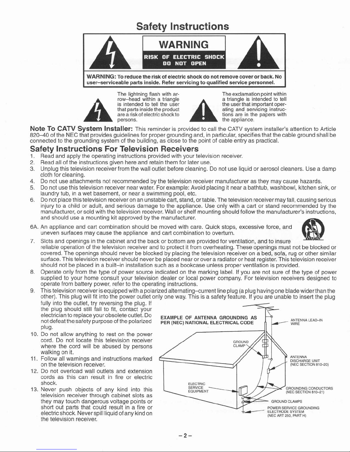
14. Ifan outside antenna isconnected to the television equipment, be sure the antenna system isgrounded soas to provide
some protection against voltage surges and built up static charges. In the U.S. Section 810 of the National Electrical
Code and inCanada Part 1of the Canadian Electrical Code provides information with respect to propergrounding ofthe
mast and supporting structure,grounding of the lead-in wire to an antenna discharge unit,size of grounding conductors,
location of antenna-d ischarge unit, connection to grounding electrodes, and requirements for the grounding electrode.
See Figure.
15. For added protection for this television receiver during a lightning storm,orwhen it is left unattended and unused for long
periods oftime, unplug it from the wall outlet and disconnect the antenna. This will prevent damage to the receiver due to
lightning and power-line surges.
16. An outside antenna system should not be located in the vicinity of overhead power lines or other electric light or power
circuits, or where it can fall into such power lines or circuits. When installing an outside antenna system extreme care
should be taken to keep from touching such power lines or circuits as contact with them might be fatal.
17. Unplug this television receiver from the wall outlet, and referservicing to qualified service personnel under the following
conditions:
a. When the power cord or plug is damaged or frayed.
b. If liquid has been spilled into the television receiver.
c. If the television receiver has been exposed to rain or water.
d. Ifthe television receiver does not operate normally by following the operating instructions.Adjust only those controls
that are covered bytheoperatinginstructionsasimproper adjustment of other controls may resultindamage and will
often require extensive work by a qualified technician to restore the television receiver to normal operation.
e. Ifthe television receiver has been dropped or the cabinet has been damaged.
f. When the television receiver exhibits a distinct change in performance - this indicates a need for service .
18. Do not attempt to service this television receiver yourself as opening or removing covers may expose you to dangerous
voltage or other hazards. Refer all servicing to qualified service personnel.
19. When replacement parts are required, be sure the service technician has used replacement parts specified by the
manufacturer that have the same characteristics as the original part. Unauthorized substitutions may result in fire,
electric shock, or other hazards.
20. Upon completion ofany service or repairs to this television receiver, ask the service technician to perform routine safety
checks to determine that the television is in safe operating condition.
21. WARNING: To
prevent
fireorshock
hazard,donot
expose
this
appliancetorainormoisture.
22. CAUTION: TO PREVENT ELECTRIC SHOCK DO NOT USE THIS (POLARIZED) PLUG WITH A RECEPTACLE OR
OTHER OUTLET UNLESS THE BLADES CAN BE FULLY INSERTED TO PREVENT BLADE EXPOSURE.
NOTE: This equipment isdesigned to operate in the U.S.A., Canada and othercountrieswhere the broadcasting system and
AC house current is exactly the same as in the U.S.A. and Canada.
Important
Information
Regarding
UseofVideo Games,
Computers
, TeletextorOther
Fixed
Image
Displays.
The extended use of fixed image program material can cause a permanent "shadow image" on the picture tube. This
background image is viewable on normal programs in the form of a stationary fixed image. This type of irreversible picture
tube deterioration can be limited by observing the following steps:
A. Reduce the brightness/contrast setting to a minimum Viewing level.
B. Do not display the fixed image for extended periods of time.
C. Turn the power off when not in actual use.
NOTE: The marking or retained image on the picture tube resulting from fixed image use is not an operating defect and as
such is notcovered byWarranty.This product isnotdesigned to display fixed image patterns for extended periods of
time.
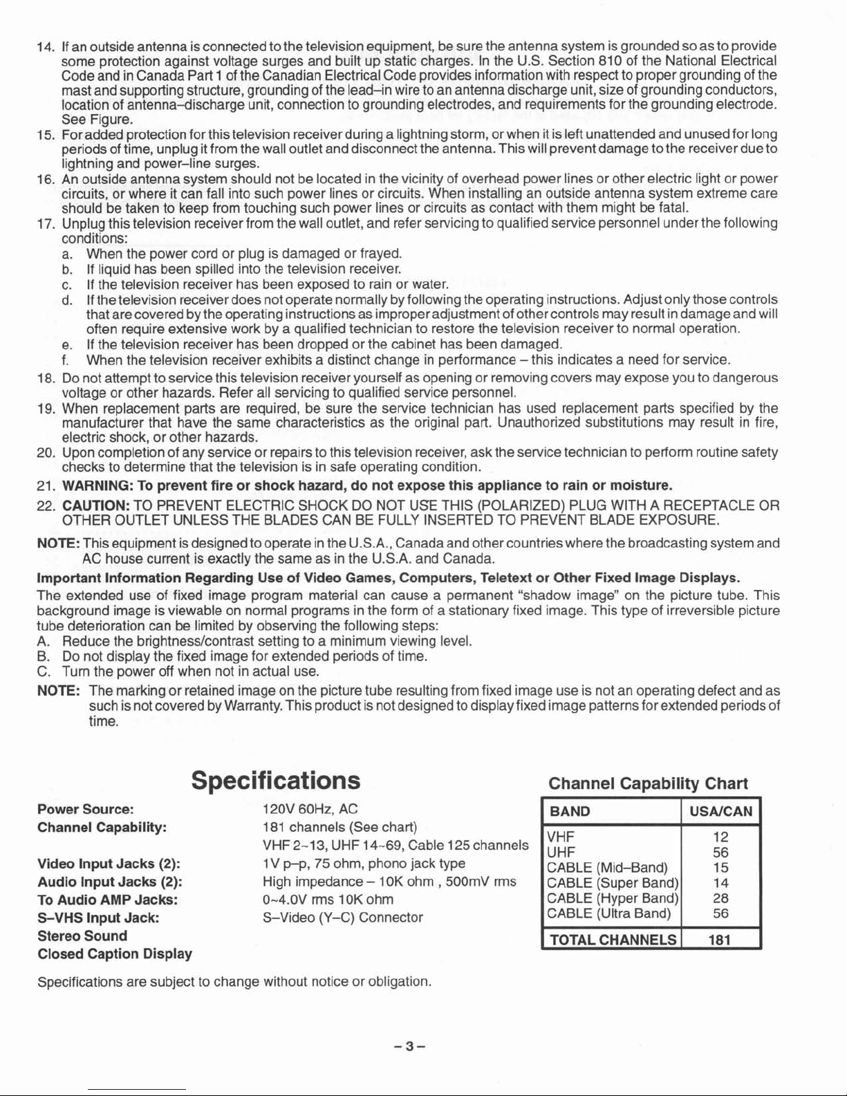
Channel
Capability
Chart
BAND
USA/CAN
VHF 12
UHF
56
CABLE (Mid-Band) 15
CABLE (Super Band) 14
CABLE (Hyper Band) 28
CABLE (Ultra Band)
56
TOTAL CHANNELS
181
Specifications
120V 60Hz, AC
181 channels (See chart)
VHF
2-13
, UHF 14
-69
,Cable 125channels
1V
p-p
, 75 ohm, phono jack type
High impedance - 10K ohm , 500mV rms
0
-4.0V
rms 10K ohm
S-Video (Y- C) Connector
Video
Input
Jacks
(2):
Audio
Input
Jacks
(2):
To
Audio
AMP
Jacks:
S-VHS
Input
Jack:
Stereo
Sound
Closed
Caption
Display
Power
Source:
Channel
Capability:
Specifications are subject to change without notice or obligation.
-3
-
Introduction
Congratulations on Your New Purchase
Your
new
video
component
features an all solid state chassis which is designed to give you
many
years of enjoyment. It
was
thoroughly tested and adjusted at the factory for best performance.
In orderfor you to take full advantage of
your
new
video component, please read and follow the installation and operating
instructions
supp
lied with this product.
Customer's Record
The
mode
land serial n
umber
of this
productmay
be found on its
back
cove
r.You should note the
mode
land
ser
ial
number
in the space provided and retain this
book
as a permanent record of
your
purchase to aid in identification in the event of
theft or loss.
Model Number:
Ser
ial Number: _
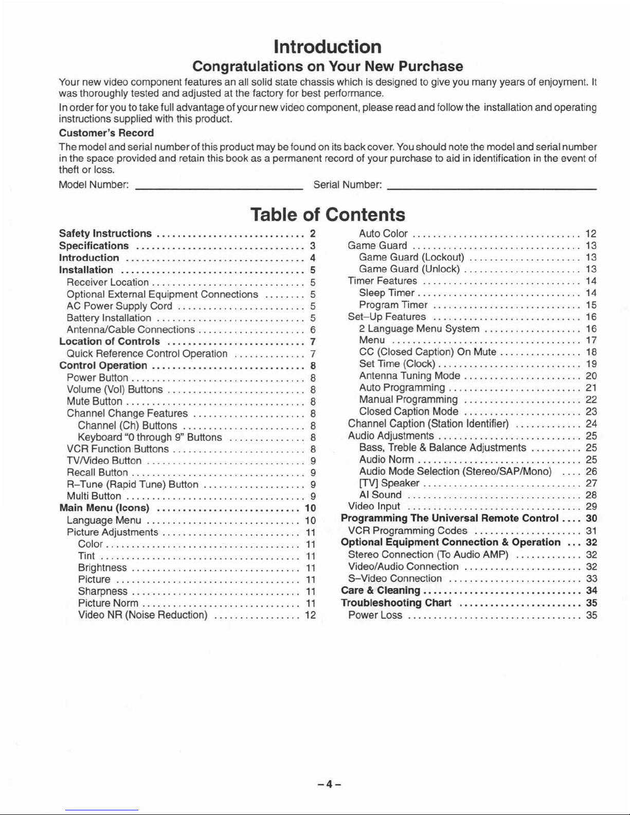
Table of Contents
Safety Instructions 2
Specifications 3
Introduction 4
Installation 5
Receiver Location . . .. . . . . . . . . . . . . . . . . . . . . . . . ...5
Optional External Equipment Connections 5
AC
PowerSupp
ly Cord 5
Battery Installation 5
Antenna/Cab
le Connections . . . .. . . . . . . . . . . . . .. .. 6
Location of Controls 7
Quick Reference Control
Ope
ration 7
Control Operation.....
. . . .. . . . . . . .. . . . . . . . . ..
..
8
Power Button . . . . . . . . . . . . . . . . . . . . . . . . . . . . . . . ...8
Volume (Vol) Buttons . . . . . . . . . . .. . . . . . . .
..
8
Mute Button . . . .. .. . . . . . . . . . . . . . . . . . . . . . . . . . . .. 8
Channel
Change
Features 8
Channel (Ch) Buttons 8
Keyboard "0 through 9" Buttons 8
VCRFunc
tion Buttons . . . . . . . . . . . . . . . . . . . . . . . . . . 8
TVN ideo Button 9
Recall Button . . . . . . . . . . . .. . . . . . . . . . . . . . . . . . . .
..
9
R-
Tune (Rapid Tune) Button 9
Multi Button 9
Main Menu (Icons) 10
Language
Menu
10
Picture Adjustments
11
Color
11
Tint
11
Brightness... . . . . . . . .. . . . . . . . . . . . . . . . . . . . . .
11
Picture
11
Sharpness
. . . . . . . . . . . . . . .. .. .. . . . . . . . . .. .
..
11
Picture
Norm
11
Video NR (Noise Reduction) 12
Auto Color . . . . . . . . . . . . . . . . . . . . . . . . . . . . . . .
..
12
Game
Guard 13
Game
Guard (Lockout) 13
Game
Guard
(Unlock) . . . . . . . . . . . . . . . . . . . . . . . 13
T
imer
Features 14
Sleep
Timer.
. . . . . . . . . . . . . . . . . . . . . . . . . . . . ...14
Program T
imer
15
Set-Up
Features 16
2
Language
Menu
System
16
Menu 17
CC (Closed Caption) On Mute . . . . . . . . . . .. . ...18
Set Time (Clock) . . . . . . .. . . . . . . . . . . . . . . . . . .
..
19
Antenna Tuning
Mode
. . . . . . . . . . . . . . . . . .. . . . . 20
Auto Programming 21
Manual Programming 22
Closed
Capt
ion
Mode
23
ChannelCapt
ion (Station Identifier) 24
Audio Adjustments . . . . . . . . . . . . . .. . . . . . . . . . . .
..
25
Bass
, Treble & Balance Adjustments 25
Audio
Norm
. . . .. . . . .. .. .. . . . . . . . . . . . . . . . ...25
Audio
Mode
Selection (Stereo/SAP/Mono) . . . . 26
[TV] Spe
aker.
. . . . . . . . .. .. . . . . . . . . . . . . . . . ...27
AI Sound 28
Video Input 29
Programming The Universal Remote Control . ...30
VCR
Programming Codes 31
Optional Equipment Connection &Operation 32
Stereo Connection (To Audio
AMP)
32
Video/Audio Connection 32
S-Video
Connection 33
Care &Cleaning . . . . .. . . . . . .. . . . . . .. . . . . . .. . ...34
Troubleshooting Chart
35
Power
Loss 35
-
4-
Installation
Receiver Location
Locate for comfortable viewing. Avoid placing where sunlight or other bright light (including reflections) will fall on the
screen.
Use of some types of fluorescent lighting can reduce remote control transmitter range.
Adequate ventilation is essential to prevent internal component failure. Keep away from areas of excessive heat or
moisture.
To insure optimum color purity do not position magnetic equipment (motors, fan, other speakers, etc.) nearby.
Optional External Equipment Connections
The Video/Audio connections between components can be made with shielded video and audio cables. For best performance, video cables should utilize 75 ohm coaxial shielded wire. Cables are available from your dealer or electronic
supply house.
Before you purchase anycables, be sure you know what type of output and input connectors your various components
require. Also determine the length of cable you'll need.
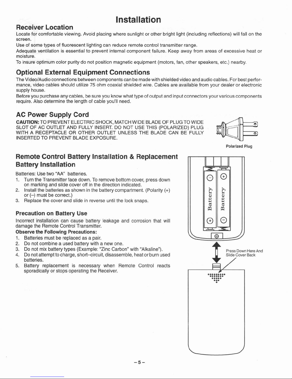
AC Power Supply Cord
CAUTION: TO PREVENT ELECTRIC SHOCK,MATCH WIDE BLADE OF PLUGTO WIDE
SLOT OF AC OUTLET AND FULLY INSERT. DO NOT USE THIS (POLARIZED) PLUG
WITH A RECEPTACLE OR OTHER OUTLET UNLESS THE BLADE CAN BE FULLY
INSERTED TO PREVENT BLADE EXPOSURE.
Polarized Plug
e
e
Remote Control Battery Installation & Replacement
Battery Installation
Batteries: Use two
"AN
' batteries.
1. Turn the Transmitter face down. To remove bottom cover, press down
on marking and slide cover off in the direction indicated.
2. Install the batteries as shown in the battery compartment. (Polarity
(+)
or
(-)
must be correct.)
3. Replace the cover and slide in reverse until the lock snaps.
Precaution on Battery Use
Incorrect installation can cause battery leakage and corrosion that will
damage the Remote Control Transmitter.
Observe the Following Precautions:
1. Batteries must be replaced as a pair.
2. Do not combine a used battery with a new one.
3. Do not mix battery types (Example: "Zinc Carbon" with "Alkaline").
4. Do not attempt tocharge,short-circuit,disassemble, heat or burn used
batteries.
5. Battery replacement is necessary when Remote Control reacts
sporadically or stops operating the Receiver.
-5-
II
I I
II
~
::J::::::::I:
<:)
e
Q Q
Q) Q)
+oJ
+oJ
+oJ
+oJ
ro ro
I:Q
I:Q
e
O
;:J,;;;[
~-
~
r<il
~
Press Down Here And
~
Slide Cover Back
•
••••••••
•••••••
0
••••
•••
•
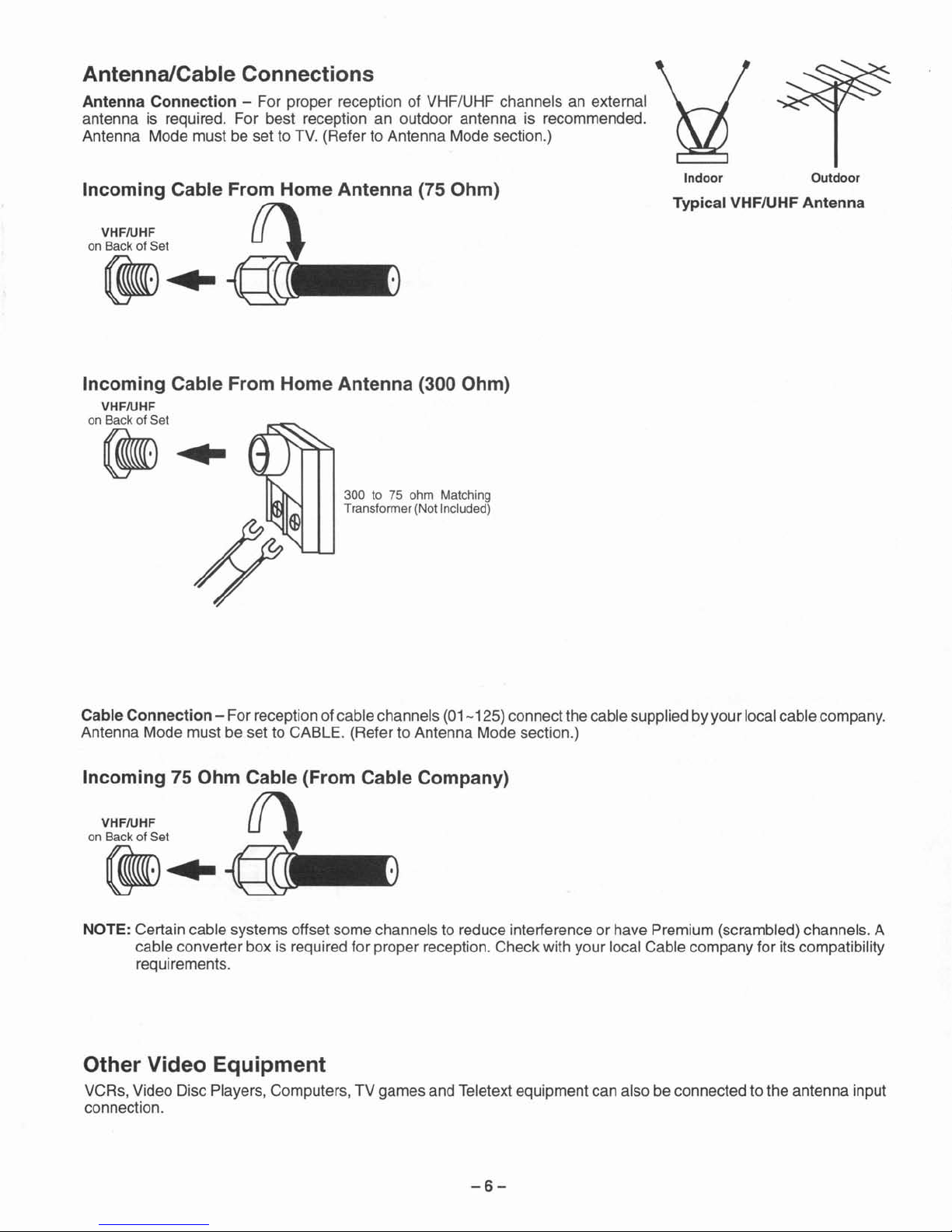
Typical VHF/UHF Antenna
Antenna/Cable Connections
Antenna Connection - For proper reception of VHF/UHF channels an external
antenna is required. For best reception an outdoor antenna is recommended.
Antenna Mode must be set to TV. (Refer to Antenna Mode section.)
Incoming Cable From Home Antenna (75 Ohm)
VHFIUHF 17'
on Back of Set
~
t
~
..
~
Incoming Cable From Home Antenna (300 Ohm)
VHF/UHF
on Back of Set
~
..
300 to 75 ohm Matching
Transformer (Not Included)
Indoor Outdoor
Cable Connection - For reception of cable channels (01
-125)
connect thecable supplied by your local cable company.
Antenna Mode must be set to CABLE. (Refer to Antenna Mode section.)
Incoming 75 Ohm Cable (From Cable Company)
VHFIUHF 17'
on Back of Set
~
t
~
..
~
NOTE: Certain cable systems offset some channels to reduce interference or have Premium (scrambled) channels. A
cable converter box is required for proper reception. Check with your local Cable company for its compatibility
requirements.
Other Video Equipment
VCRs, Video Disc Players, Computers , TV games and Teletext equipment can also be connected to the antenna input
connection.
-6-
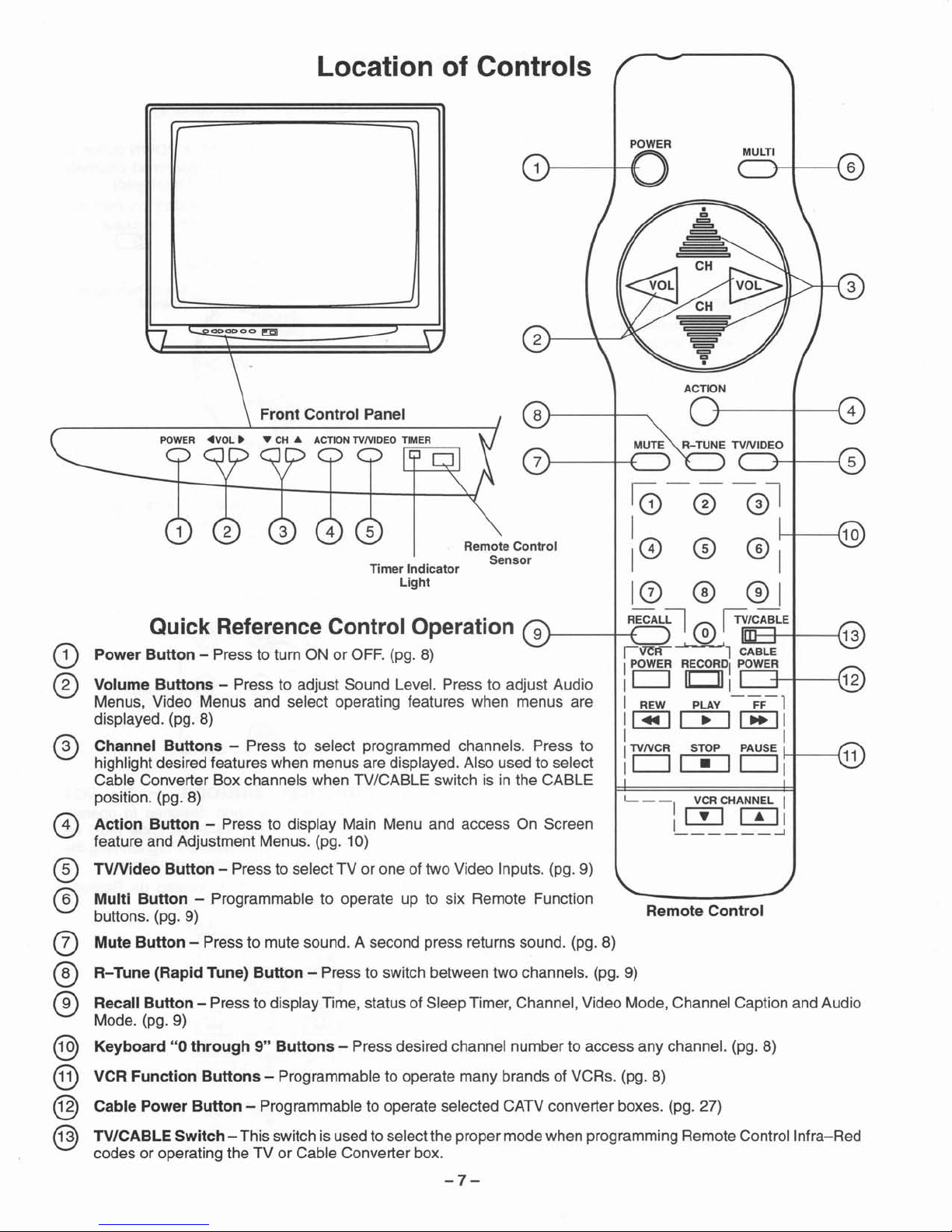
Location of Controls
r
+-----+----{
4
ACTION
Remote
Control
1- - - VCR CHANNEL I
I
[I]
[TI
l
______
-1
1
0-
0 -®l
I
10 0 0 1
10 0
01
J-
__
-t-+RECAL~
®
~/IC
I-_
AB+L
_
E
-t--
_ --(
i'lC"li
1 CABLE
IPOWER RECORD, POWER
I
CJ
1CJI
1
+-t---{
I REW PLAY -
FF-l
I
~
[::::E]
~
I
I I
ITVNCR STOP PAUSE
H----{
I
CJ
c:::D
CJ
I
Remote Control
Sensor
Timer Indicator
Light
Front
Control Panel
POWER
Quick Reference Control Operation
Power
Button
- Press to turn ON or OFF. (pg. 8)
Volume
Buttons
- Press to adjust Sound Level. Press to adjust Audio
Menus, Video Menus and select operating features when menus are
displayed. (pg. 8)
Channel
Buttons
- Press to select programmed channels. Press to
highlight desired features when menus are displayed. Also used to select
Cable Converter Box channels when TV/CABLE switch is in the CABLE
position. (pg. 8)
Action Button - Press to display Main Menu and access On Screen
feature and Adjustment Menus. (pg. 10)
TVNideo
Button
- Press to select TV or one of two Video Inputs. (pg. 9)
Multi
Button
- Programmable to operate up to six Remote Function
buttons. (pg. 9)
Mute
Button
- Press to mute sound. A second press returns sound. (pg. 8)
R-Tune (Rapid Tune)
Button
- Press to switch between two channels. (pg. 9)
Recall
Button
- Press to display Time, status of Sleep Timer, Channel, Video Mode, Channel Caption and Audio
Mode. (pg. 9)
Keyboard"0through9"Buttons
- Press desired channel number to access any channel. (pg. 8)
VCR Function
Buttons
- Programmable to operate many brands of VCRs. (pg. 8)
Cable Power
Button
- Programmable to operate selected CATV converter boxes. (pg. 27)
TV/CABLE Switch - This switch is used to select the proper mode when programming Remote Control Infra-Red
codes or operating the TV or Cable Converter box.
CD
®
o
®
®
o
®
®
®
@
@
@
-7-
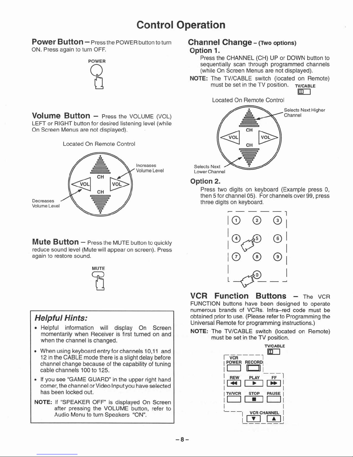
Control Operation
Power Button - Pressthe POWER buttonto turn
ON. Press again to turn OFF.
POWER
~
Channel Change- (Two
options)
Option 1.
Press the CHANNEL (CH) UP or DOWN button to
sequentially scan through programmed channels
(while On Screen Menus are not displayed).
NOTE: The TV/CABLE switch (located on Remote)
must be set in the TV position.
TV/CABLE
[gLJ
Located On Remote Control
Option 2.
Press two digits on keyboard (Example press 0,
then 5 for channel 05). Forchannels over 99, press
three digits on keyboard.
IvcR----l
IPOWER RECORDI
ICJ
1011
I REW PLAY -
FF-l
I~I.I~I
I I
I
TVNCR
STOP PAUSE I
ICJI-ICJI
I I
'- -
-I
VCR CHANNEL I
I
[!]
[TIl
______
---J
Selects Next Higher
Channel
~----l
10
0
0\
10~
®I
I V I
10
0
01
l4--
J
Selects Next
Lower Channel
VCR Function Buttons - The VCR
FUNCTION buttons have been designed to operate
numerous brands of VCRs. Infra-red code must be
obtained priorto use. (Please refer to Programming the
Universal Remote for programming instructions.)
NOTE: The TV/CABLE switch (located on Remote)
must be set in the TV position.
TV/CABLE
[gLJ
Increases
Volume Level
Located On Remote Control
MUTE
(]
Helpful Hints:
• Helpful information will display On Screen
momentarily when Receiver is first turned on and
when the channel ischanged.
• When using keyboard entry for channels
10,11
and
12 in the CABLE modethere is a slight delay before
channel change because of the capability of tuning
cable channels 100 to 125.
• If you see "GAME GUARD" in the upper right hand
corner,the channel or Video Input you haveselected
has been locked out.
NOTE: If "SPEAKER OFF" is displayed On Screen
after pressing the VOLUME button, refer to
Audio Menu to turn Speakers "ON".
Decreases
Volume Level
Mute Button - Press the MUTE button to quickly
reduce sound level (Mute will appear on screen). Press
again to restore sound.
Volume Button - Press the VOLUME (VOL)
LEFT or RIGHT button for desired listening level (while
On Screen Menus are not displayed).
-8-
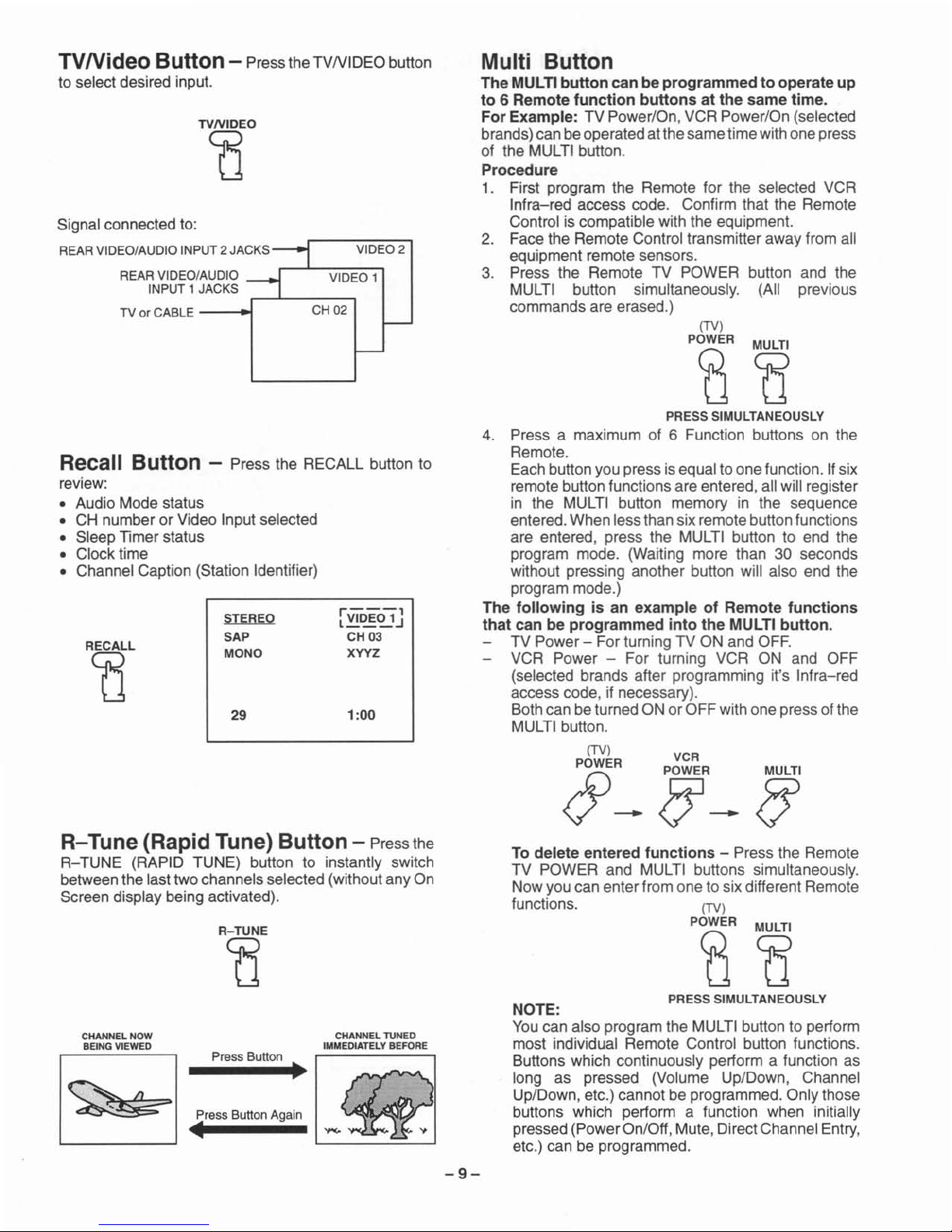
TVNideo
Button - Pressthe TVNIDEO button
to select desired input.
Multi Button
The MULTI
button
can be
programmed
to operateup
to 6 Remote
function
buttons
at the same time.
For Example: TV Power/On, VCR Power/On (selected
brands)can be operated at thesame time withone press
of the MULTIbutton.
Procedure
1. First program the Remote for the selected VCR
Infra-red access code. Confirm that the Remote
Control is compatible with the equipment.
2. Face the Remote Control transmitteraway from all
equipment remote sensors.
3. Press the Remote TV POWER button and the
MULTI button simultaneously. (All previous
commands are erased.)
VIDEO 2
VIDEO 1
CH 02
Signal connected to:
REAR VIDEO/AUDIO INPUT 2 JACKS
REAR VIDEO /AUDIO
INPUT 1 JACKS
TV or CABLE
----<~
R-
Tune (Rapid Tune) Button - Press the
R-
TUNE (RAPID TUNE) button to instantly switch
betweenthe lasttwo channels selected (withoutany On
Screen display being activated).
Recall Button - Press the RECALL button to
review:
• Audio Mode status
• CH number or Video Input selected
• Sleep Timer status
• Clock time
• Channel Caption (Station Identifier)
NOTE:
Youcan also program the MULTI button to perform
most individual Remote Control button functions.
Buttons which continuously perform a function as
long as pressed (Volume Up/Down, Channel
Up/Down, etc.) cannot be programmed. Only those
buttons which perform a function when initially
pressed (PowerOn/Off,Mute, DirectChannel Entry,
etc.) can be programmed.
To delete entered
functions
- Press the Remote
TV POWER and MULTI buttons simultaneously.
Nowyou can enter from one to six different Remote
functions.
(TV)
P~R
cg
PRESS SIMULTANEOUSLY
(TV)
P~R
cs
PRESS SIMULTANEOUSLY
4. Press a maximum of 6 Function buttons on the
Remote.
Eachbutton you press is equal to one function. Ifsix
remote button functions are entered,all will register
in the MULTI button memory in the sequence
entered.When less than sixremotebutton functions
are entered, press the MULTI button to end the
program mode. (Waiting more than
30 seconds
without pressing another button will also end the
program mode.)
The
following
is an exampleofRemote
functions
that
can be programmed
into
the MULTI button.
TV Power - For turning TV ON and OFF.
VCR Power - For turning VCR ON and OFF
(selected brands after programming it's Infra-red
access code, if necessary).
Bothcan be turned ON orOFF with one pressofthe
MULTI button.
(TV) VCR
J"-
~R_
JJ
1:00
rVIDE01'
l .J
CH03
XYYZ
29
STEREO
SAP
MONO
CHANNEL TUNED
IMMEDIATELY BEFORE
R-TUNE
CO
Press Button
Press Button Again
•
~
r~
..._..,,'\.
_
RECALL
t1
CHANNEL NOW
BEING VIEWED
-9-
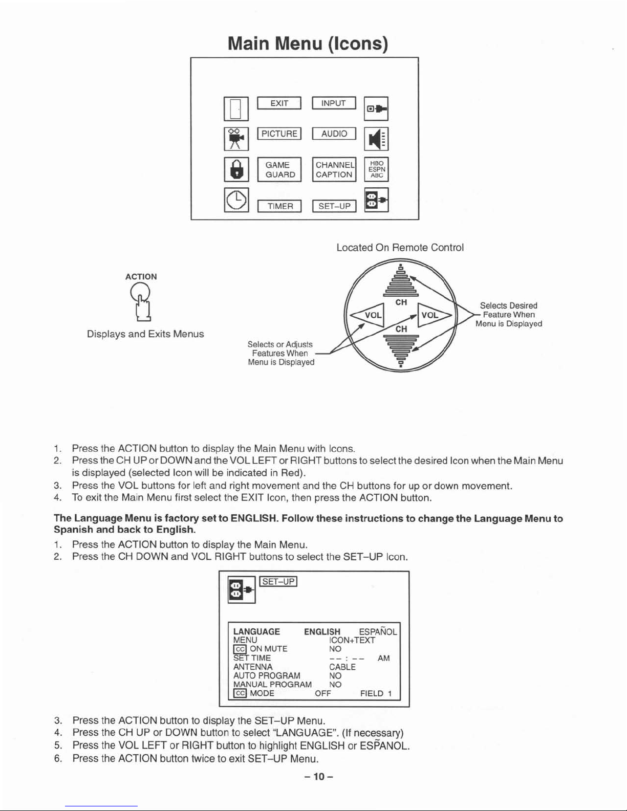
Main Menu (Icons)
TIMER I ISE
T-UP
I
ACTION
ca
Displays and Exits Menus
EXIT I I
IPICTURE I
Selects or Adjusts
Features When
Menu is Displayed
INPUT
AUDIO
Located On Remote Control
Selects Desired
Feature When
Menu is Displayed
1. Press the ACTION button to display the Main Menu with Icons.
2. Press the CH UP or DOWN and the VOL LEFTor RIGHT buttonsto select the desired Iconwhen the Main Menu
is displayed (selected Icon will be indicated in Red).
3. Press the VOL buttons for left and right movement and the CH buttons for up or down movement.
4. Toexit the Main Menu first select the EXIT Icon, then press the ACTION button.
The Language Menu is factory set to ENGLISH. Follow these instructions to change the Language Menu to
Spanish and back to English.
1. Press the ACTION button to display the Main Menu.
2. Press the CH DOWN and VOL RIGHT buttons to select the SET-UP Icon.
181'
SET-UPI
LANGUAGE ENGLISH ESPANOL
MENU ICON+TEXT
@9
ON MUTE NO
SET TIME
--
--
AM
ANTENNA CABLE
AUTO PROGRAM NO
MANUAL PROGRAM NO
@9MODE OFF FIELD 1
3. Press the ACTION button to display the
SET-UP
Menu.
4. Press the CH UP or DOWN button to select "LANGUAGE". (If necessary)
5. Press the VOL LEFT or RIGHT button to highlight ENGLISH or ESPANOL.
6. Press the ACTION button twice to exit
SET-UP
Menu.
-10-
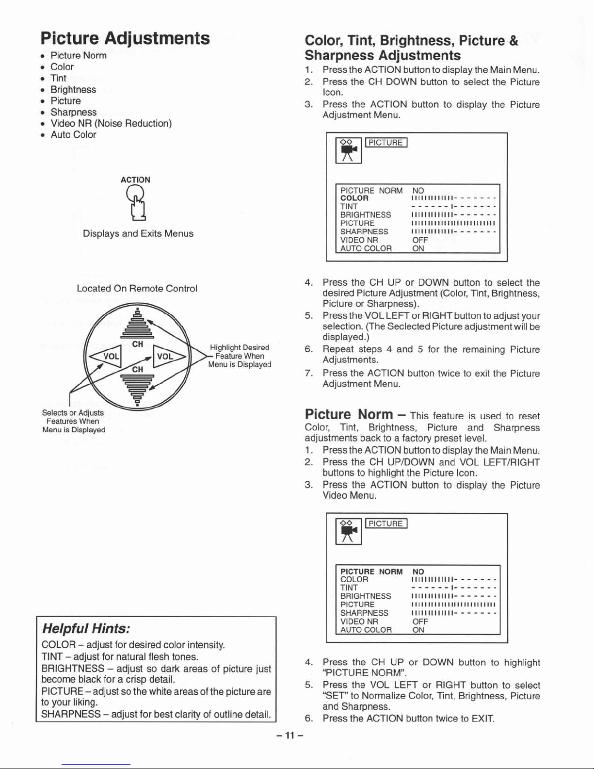
Picture Adjustments
• Picture Norm
• Color
• Tint
• Brightness
• Picture
• Sharpness
• Video NR (Noise Reduction)
• Auto Color
Color, Tint, Brightness, Picture &
Sharpness Adjustments
1. Pressthe ACTION button to display the Main Menu.
2. Press the CH DOWN button to select the Picture
Icon.
3. Press the ACTION button to display the Picture
Adjustment Menu.
It
I
'P
ICTURE I
ACTION
ca
Displays and Exits Menus
PICTURE NORM
COLOR
TINT
BRIGHTNESS
PICTURE
SHARPNESS
VIDEO NR
AUTO COLOR
NO
1111111111111
- - - - - - -
- - - - - - 1- - - - - - -
1111111111111- - - - -
--
11111111111111111
111
111111
1111111111111- - - - -
_.
OFF
ON
Located On Remote Control
Highlight Desired
Feature When
Menu is Displayed
Selects or Adjusts
Features When
Menu is Displayed
4. Press the CH UP or DOWN button to select the
desired PictureAdjustment (Color,Tint, Brightness,
Picture or Sharpness).
5. Press the VOLLEFT or RIGHT button to adjust your
selection. (The Seclected Pictureadjustment willbe
displayed.)
6. Repeat steps 4 and 5 for the remaining Picture
Adjustments.
7. Press the ACTION button twice to exit the Picture
Adjustment Menu.
Picture Norm - This feature is used to reset
Color, Tint, Brightness, Picture and Sharpness
adjustments back to a factory preset level.
1. Pressthe ACTION buttonto display the Main Menu.
2. Press the CH UP/DOWN and VOL LEFT/RIGHT
buttons to highlight the Picture Icon.
3. Press the ACTION button to display the Picture
Video Menu.
It
I
'P
ICTURE I
4. Press the CH UP or DOWN button to highlight
"PICTURE NORM".
5. Press the VOL LEFT or RIGHT button to select
"SET" to Normalize Color, Tint, Brightness, Picture
and Sharpness.
6. Press the ACTION button twice to EXIT.
Helpful Hints:
COLOR - adjust for desired color intensity.
TINT - adjust for natural flesh tones.
BRIGHTNESS - adjust so dark areas of picture just
become black for a crisp detail.
PICTURE- adjust sothe white areas of the picture are
to your liking.
SHARPNESS - adjust for best clarity of outline detail.
-11
-
PICTURE NORM
COLOR
TINT
BRIGHTNESS
PICTURE
SHARPNESS
VIDEO NR
AUTO COLOR
NO
111111
1111111- - - - - - •
- - - - - - 1- - - - - - •
1111111111111- - - - - - •
11111111111111111111111111
1111111111111- - - - - - -
OFF
ON
 Loading...