

Panasonic CNZ3182, CNC7T101, CNC7S101, CNC1H101 Datasheet
Optoisolators (Photocouplers)
CNC7S101,CNZ3182,CNC7T101,CNC1H101
Optoisolators
Overview
CNC7S101 is an AC input compatible optoisolator in which two
GaAs high output infrared light emitting diode chips are connected
in reverse parallel as light emitting elements, and opitically are
connected to a high sensitivity Si phototransistor chip as a light
detecting element in a small DIL 4-pin package.
This optoisolator series also includes the two-channel CNZ3182,
the three-channel CNC7T101, and the four-channel CNC1H101.
The CNC7S101 series has a number of excellent features,
including high I/O isolation voltage and current transfer ratio (CTR),
as well as high speed response and high reliability.
Features
AC input support
High I/O isolation voltage : V
= 5000 V
ISO
rms
(min.)
Fast response : tr = 4 µs, tf = 3 µs
UL listed (UL File No. E79920)
Applications
Telephones
Telephone switches
Programmable controllers
AC/DC input modules for measuring
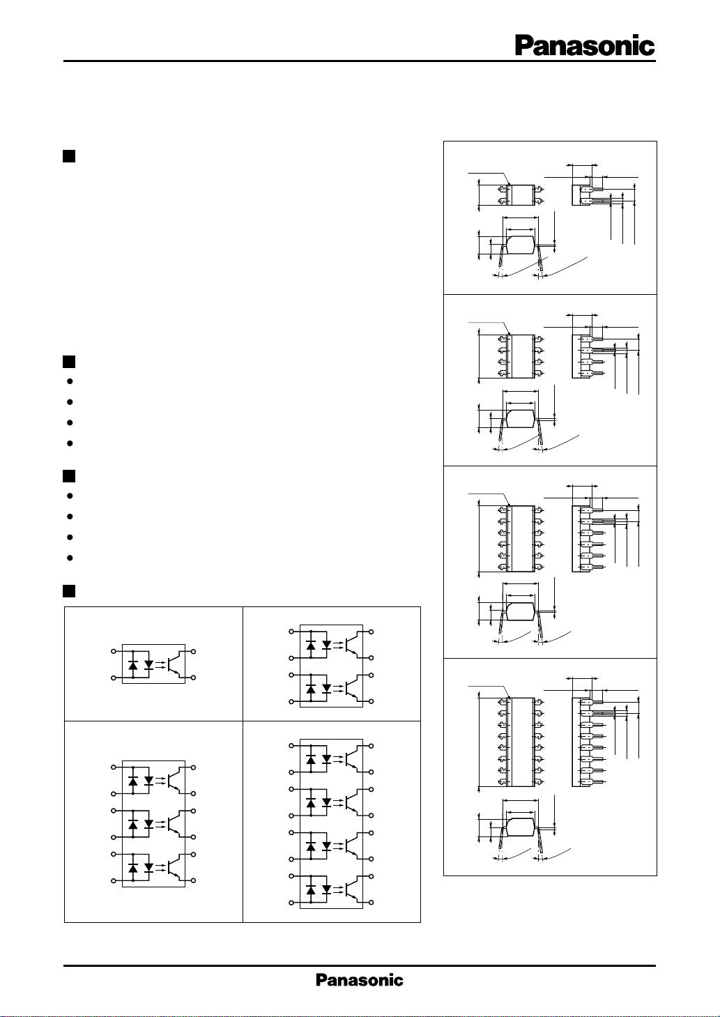
Pin Connection
CNC7S101
1
2
CNC7T101
1
2
3
4
5
6
4
3
Top View Top View
12
11
10
9
8
7
Top View
CNZ3182
1
2
3
4
CNC1H101
1
2
3
4
5
6
7
8
8
7
6
5
16
15
14
13
12
11
10
9
Top View
CNC7S101
LED Mark
1
23
4.58±0.3
2.0
3.85±0.3
CNZ3182
LED Mark
1
2
3
9.66±0.3
4
2.0
3.85±0.3
CNC7T101
LED Mark
1
2
3
4
14.74±0.3
5
6
2.0
3.85±0.3
CNC1H101
LED Mark
1
2
3
4
5
19.82±0.5
6
7
8
2.0
3.85±0.3
7.62±0.3
6.2±0.5
0 to 15˚
7.62±0.3
6.2±0.5
0 to 15˚
7.62±0.3
6.2±0.5
0 to 15˚
7.62±0.3
6.2±0.5
0 to 15˚
5.2 max.
4
–0
+0.15
0.25
0 to 15˚
5.2 max.
5
6
7
8
–0
+0.15
0.25
0 to 15˚
5.2 max.
12
11
10
9
8
7
–0
+0.15
0.25
0 to 15˚
5.2 max.
16
15
14
13
12
11
10
9
–0
+0.15
0.25
0 to 15˚
Unit : mm
2.54 min.0.5 min.
4-0.5±0.1
4-1.2±0.15
2.54±0.25
1: Anode/Cathode
2: Cathode/Anode
3: Emitter
4: Collector
Unit : mm
2.54 min.0.5 min.
8-0.5±0.1
8-1.2±0.15
2.54±0.25
1,3: Anode/Cathode
2,4: Cathode/Anode
5,7: Emitter
6,8: Collector
Unit : mm
2.54 min.0.5 min.
12-0.5±0.1
2.54±0.25
12-1.2±0.15
1,3,5: Anode/Cathode
2,4,6: Cathode/Anode
7,9,11: Emitter
8,10,12: Collector
Unit : mm
2.54 min.0.5 min.
16-0.5±0.1
2.54±0.25
16-1.2±0.15
1,3,5,7: Anode/Cathode
2,4,6,8: Cathode/Anode
9,11,13,15: Emitter
10,12,14,16: Collector
1
Optoisolators (Photocouplers) CNC7S101,CNZ3182,CNC7T101,CNC1H101
Absolute Maximum Ratings (Ta = 25˚C)
Parameter
Input (Light
emitting diode)
Forward current (DC)
Pulse forward current
Power dissipation
Collector current
Output (Photo
transistor)
Collector to emitter voltage
Emitter to collector voltage
Collector power dissipation
Total power dissipation
Isolation voltage, input to output
Operating ambient temperature
Storage temperature
*1
Pulse width ≤ 100 µs, repeat 100 pps
*2
Input power derating ratio is 0.75 mW/˚C at Ta ≥ 25˚C.
*3
Output power derating ratio is 1.5 mW/˚C at Ta ≥ 25˚C.
*4
AC 1 min. RH < 60 %
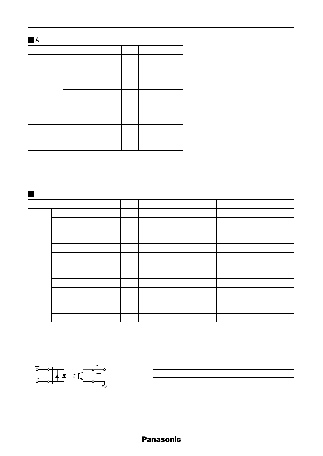
Electrical Characteristics (Ta = 25˚C)
Parameter
Input
characteristics
Output
characteristics
Transfer
characteristics
*1
DC current transfer ratio (CTR) is a ratio of output current against DC input current
*2
tr : Time required for the collector current to increase from 10% to 90% of its final value
*3
tf : Time required for the collector current to decrease from 90% to 10% of its initial value
*4
I
I
F1
I
F2
Forward voltage (DC) VFIF = ±50mA 1.35 1.5 V
Capacitance between pins
Collector cutoff current I
Collector to emitter voltage V
Emitter to collector voltage V
Collector to emitter capacitance
DC current transfer ratio
Isolation capacitance, input to output
Isolation resistance, input to output
Rise time
Fall time
Collector to emitter saturation voltage
Collector current ratio
IC2 (IF=IF2, VCE=5V)
=
C (Ratio)
IC1 (IF=IF1, VCE=5V)
1
2
I
C1
I
4
C2
3
Symbol
Symbol
I
F
*1
I
FP
*2
P
D
I
C
V
CEO
V
ECO
*3
P
C
P
T
*4
V
ISO
T
opr
T
stg
Ratings Unit
±50 mA
±1A
75 mW
50 mA
80 V
7V
150 mW
200 mW
5000 V
–30 to +100
–55 to +125
rms
˚C
˚C
Conditions min typ max Unit
CtVR = 0V, f = 1MHz 35 pF
CEOVCE
CEOIC
ECOIE
CCV
CTR
C
ISOf
R
ISOVISO
*2
t
r
*3
t
f
V
CE(sat)IF
I
C(Ratio)
V
CE
= 20V 5 100 nA
= 100µA80V
= 10µA7V
= 10V, f = 1MHz 3 pF
CE
*1, 5
V
= 5V, IF = ±1mA 20 300 %
CE
= 1MHz 0.6 pF
= 500V 10
V
= 10V, IC = 2mA, 4 µs
CC
11
Ω
RL = 100Ω 3 µs
= ±20mA, IC = 1mA 0.1 0.2 V
*4
V
= 5V, IF = 1mA 0.33 1.0 3.0 –
CE
*5
CTR classifications
Class General R S
CTR (%) 20 to 300 50 to 150 100 to 300
2
 Loading...