

Panasonic CNB1304H Datasheet
Reflective Photosensors (Photo Reflectors)
ON2175
Reflective Photosensor
Tape end sensor for DAT
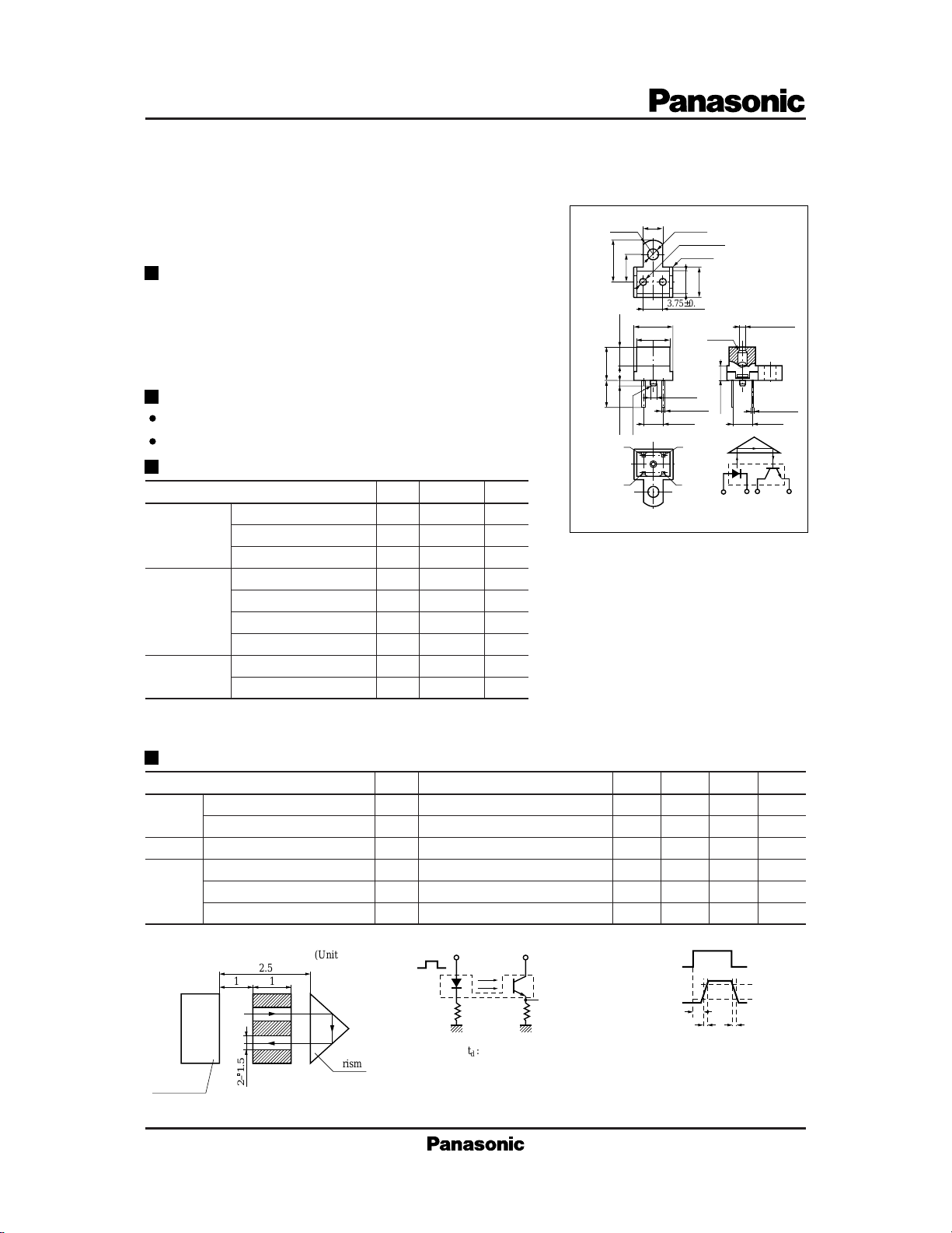
Outline
ON2175 is a sensor which consists of a high efficiency GaAs
infrared light emitting diode and a high sensitivity Si phototransistor
which are arranged together in the same direction. It detects the
beginning and end of a tape based on changes in the amount of light
reflected from a prism which is situated outside of the sensor.
Features
Fast response
Small size and light weight
4.0±0.3
(R2.3)
8.3±0.3
6.0±0.15
4.0±0.31.0±0.3
8.3±0.35.0 min.
42
ø2.2±0.3
3.75±0.15
+0
8.0
–0.3
7.0±0.3
ø1.2
2-0.4±0.2
(3.75) (3.75)
(C0.2)
2-ø1.2±0.15
(4-R0.3)
+0
–0.3
5.0
6.5±0.3
(C0.3)
+0
–0.3
3.0±0.3
Unit : mm
2-ø1.2±0.15
+0.2
2-0.15
–0.1
Absolute Maximum Ratings (Ta = 25˚C)
Parameter
Reverse voltage (DC)
Input (Light
emitting diode)
Forward current (DC)
Power dissipation
Collector current
Output (Photo
transistor)
Collector to emitter voltage
Emitter to collector voltage
Collector power dissipation
Temperature
*1
Input power derating ratio is 1.0 mW/˚C at Ta ≥ 25˚C.
*2
Output power derating ratio is 1.34 mW/˚C at Ta ≥ 25˚C.
Operating ambient temperature
Storage temperature T
Symbol
V
R
I
F
*1
P
D
I
C
V
CEO
V
ECO
*2
P
C
T
opr
stg
Electrical Characteristics (Ta = 25˚C)
Parameter
Input
characteristics
Output characteristics
Transfer
characteristics
Forward voltage (DC)
Reverse current (DC)
Collector cutoff current
Collector current
Response time
Collector to emitter saturation voltage
*1
I
Measurement method
C
(Unit : mm )
11
ON2175
2.5
2– 1.5
prism
Symbol
VFIF = 50mA 1.5 V
IRVR = 3V 10 µA
I
CEOVCE
*1
I
C
*2
tr , t
f
V
CE(sat)IF
Ratings Unit
3V
(Note) ( ) Dimension is reference
31
1432
Pin connection
50 mA
75 mW
20 mA
30 V
5V
100 mW
–25 to +85 ˚C
–30 to +100
˚C
Conditions min typ max Unit
= 10V 0.2 µA
V
= 5V, IF = 20mA, RL = 100Ω 30 µA
CE
V
= 10V, IC = 0.5mA, RL = 100Ω
CC
6 µs
= 50mA, IC = 0.1mA 0.5 V
*2
Switching time measurement circuit
Sig.IN
50Ω R
: Delay time
t
d
: Rise time (Time required for the collector current to increase from
t
r
10% to 90% of its final value)
: Fall time (Time required for the collector current to decrease from
t
f
90% to 10% of its initial value)
V
CC
Sig.OUT 10%
L
(Input pulse)
(Output pulse)
t
d
t
r
t
90%
f
1
 Loading...