

Panasonic CNB1002, CNB1001 Datasheet
Reflective Photosensors (Photo Reflectors)
,,
,,,
,,,
,,
,,,
,,,
,,,
CNB1001, CNB1002
Reflective Photosensors
Overview
CNB1001 and CNB1002 are a small, thin SMD-compatible
reflective photosensor consisting of a high efficiency GaAs infrared
light emitting diode which is integrated with a high sensitivity Si
phototransistor in a single resin package.
Features
Reflow-compatible reflective photosensor
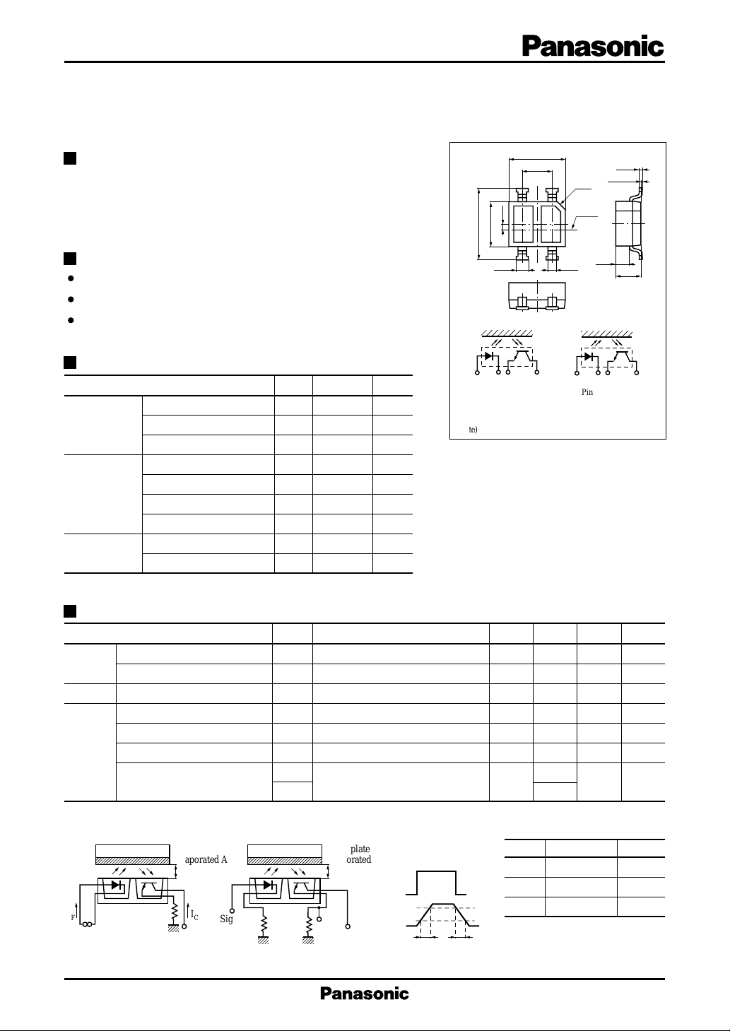
Ultraminiature, thin type : 2.7 × 3.4 mm (height : 1.5 mm)
Visible light cutoff resin is used
Absolute Maximum Ratings (Ta = 25˚C)
Input (Light
emitting diode)
Output (Photo
transistor)
Temperature
Parameter
Reverse voltage (DC)
Forward current (DC)
Power dissipation
Collector current
Collector to emitter voltage
Emitter to collector voltage
Collector power dissipation
Operating ambient temperature
Storage temperature
Symbol
V
R
I
F
*1
P
D
I
C
V
CEO
V
ECO
*2
P
C
T
opr
T
stg
Ratings Unit
6V
50 mA
75 mW
20 mA
35 V
6V
75 mW
–25 to +85 ˚C
– 40 to +100
˚C
3.4
1.8
13
0.35
2.7
4.3±0.3
24
4-0.7 4-0.5
CNB1001
1432
Pin connection
1: Anode 3: Emitter
2: Cathode 4: Collector
(Note) Tolerance unless otherwise specified is ±0.2
*1
Input power derating ratio is
C0.5
Chip
center
0.85
CNB1002
3214
Pin connection
1: Emitter 3: Anode
2: Collector 4: Cathode
1.0 mW/˚C at Ta ≥ 25˚C.
*2
Output power derating ratio is
1.0 mW/˚C at Ta ≥ 25˚C.
Unit : mm
0.15
+0.1
0.05
–0.05
1.5
Electrical Characteristics (Ta = 25˚C)
Parameter
Input
characteristics
Output characteristics
Forward voltage (DC)
Reverse current (DC)
Collector cutoff current
Collector current
Transfer
characteristics
Leakage current
Collector to emitter saturation voltage
Response time
*1
Output Current (IC) measurement
method (see figure below.) circuit (see figure below.)
Glass plate
Evaporated Al
d = 1mm
I
F
Input and output are handled electrically.
This product is not designed to withstand radiation.
R
I
L
C
Sig.IN
V
CC
Symbol
VFIF = 20mA 1.2 1.4 V
IRVR = 3V 10 µA
I
CEOVCE
*1
I
V
C
CC
IDV
CC
V
CE(sat)IF
*2
Response time measurement
50Ω
= 20mA, IC = 0.1mA 0.4 V
*2
t
V
r
CC
*2
t
RL = 1000Ω 40
f
Glass plate
Evaporated Al
Sig.
OUT
R
L
Conditions min typ max Unit
= 20V 100 nA
= 2V, IF = 4mA. RL = 100Ω, d = 1mm
23 160 µA
= 2V, IF = 4mA, RL = 100Ω 100 nA
= 5V, IC = 0.1mA, 30
Color indication of classifications
Class IC (µA) Color
Q 23 to 50 Orange
R 41 to 90 White
90%
10%
S 74 to 160
Light blue
d = 1mm
V
CC
Sig.IN
Sig.OUT
tr : Rise time
: Fall time
t
f
t
r
t
f
µs
1
CNB1001,CNB1002 Reflective Photosensors (Photo Reflectors)
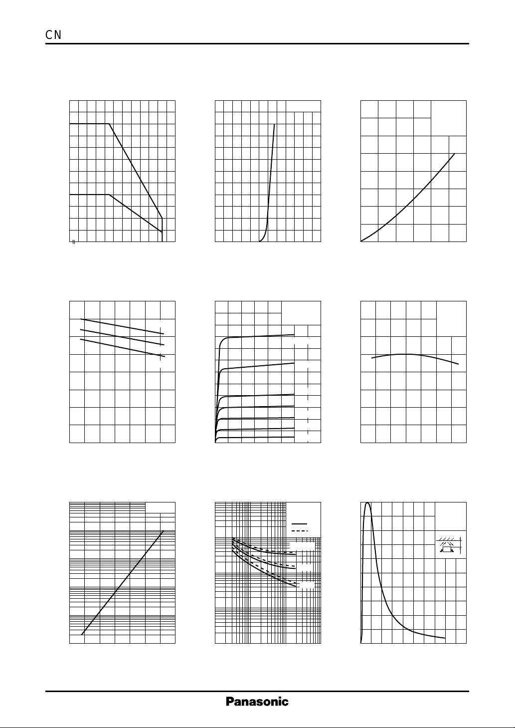
IF , I
— Ta
60
(mA)
C
50
, I
F
40
30
20
10
Forward current, collector current I
0
0 20406080100
– 25
C
I
F
I
C
Ambient temperature Ta (˚C )
V
— Ta
F
IF = 50mA
(V)
F
1.6
1.2
0.8
10mA
1mA
60
50
40
(mA)
F
30
20
Forward current I
10
0
0.4 0.8 1.2 1.6 2.42.0
0
Forward voltage VF (V)
600
500
400
(µA)
C
300
I
I
F
C
— V
— V
F
CE
Ta = 25˚C
d = 1mm
Ta = 25˚C
IF = 20mA
15mA
800
600
(µA)
C
400
200
Collector current I
0
0
Forward current IF (mA)
160
120
(%)
C
80
I
— I
C
F
V
= 5V
CC
Ta = 25˚C
= 100Ω
R
L
d = 1mm
81624
I
— Ta
C
V
= 2V
CC
= 4mA
I
F
= 100Ω
R
L
Forward voltage V
0.4
0
– 40 – 20
0 20406080100
Ambient temperature Ta (˚C )
I
10
1
(µA)
–1
10
CEO
–2
10
Dark current I
–3
10
–4
10
CEO
0 20406080100– 40 – 20
Ambient temperature Ta (˚C )
— Ta
VCE = 10V
200
Collector current I
100
0
2 3
1 45678
0
Collector to emitter voltage VCE (V)
tr , t
— I
3
10
2
10
(µs)
f
, t
r
10
1
Rise time , fall time t
–1
10
–2
10
f
–1
Collector current IC (mA)
C
V
Ta = 25˚C
: t
: t
RL = 2kΩ
11010
10mA
8mA
6mA
4mA
2mA
CC
1kΩ
100Ω
= 5V
Relative output current I
100
r
f
(%)
C
Relative output current I
40
0
0 20406080100– 40 – 20
Ambient temperature Ta (˚C )
I
— d
C
80
60
40
20
0
2 46 108
0
Distance d (mm)
= 2V
V
CE
Ta = 25˚C
= 4mA
I
F
d
2
 Loading...